EP2432720B1 - Manueller bandapplikator, insbesondere korrektor - Google Patents
Manueller bandapplikator, insbesondere korrektor Download PDFInfo
- Publication number
- EP2432720B1 EP2432720B1 EP10728779.9A EP10728779A EP2432720B1 EP 2432720 B1 EP2432720 B1 EP 2432720B1 EP 10728779 A EP10728779 A EP 10728779A EP 2432720 B1 EP2432720 B1 EP 2432720B1
- Authority
- EP
- European Patent Office
- Prior art keywords
- application head
- magnetic member
- casing
- applicator
- strip
- Prior art date
- Legal status (The legal status is an assumption and is not a legal conclusion. Google has not performed a legal analysis and makes no representation as to the accuracy of the status listed.)
- Not-in-force
Links
- 239000000463 material Substances 0.000 claims description 27
- 238000006073 displacement reaction Methods 0.000 claims description 26
- 239000000758 substrate Substances 0.000 claims description 20
- 230000003213 activating effect Effects 0.000 claims 3
- 230000005404 monopole Effects 0.000 claims 1
- 238000012546 transfer Methods 0.000 description 8
- 230000008901 benefit Effects 0.000 description 5
- 230000007246 mechanism Effects 0.000 description 5
- 238000012937 correction Methods 0.000 description 4
- 230000000694 effects Effects 0.000 description 4
- 238000013519 translation Methods 0.000 description 4
- 230000036461 convulsion Effects 0.000 description 3
- 238000013016 damping Methods 0.000 description 3
- 230000008859 change Effects 0.000 description 2
- 238000006243 chemical reaction Methods 0.000 description 2
- 239000011248 coating agent Substances 0.000 description 2
- 238000000576 coating method Methods 0.000 description 2
- 238000013461 design Methods 0.000 description 2
- 239000008188 pellet Substances 0.000 description 2
- 230000004044 response Effects 0.000 description 2
- 238000004804 winding Methods 0.000 description 2
- 230000004308 accommodation Effects 0.000 description 1
- 230000009471 action Effects 0.000 description 1
- 239000000853 adhesive Substances 0.000 description 1
- 230000001070 adhesive effect Effects 0.000 description 1
- 238000013459 approach Methods 0.000 description 1
- 238000005452 bending Methods 0.000 description 1
- 230000005540 biological transmission Effects 0.000 description 1
- 230000015556 catabolic process Effects 0.000 description 1
- 230000003749 cleanliness Effects 0.000 description 1
- 230000000295 complement effect Effects 0.000 description 1
- 230000006835 compression Effects 0.000 description 1
- 238000007906 compression Methods 0.000 description 1
- 230000007547 defect Effects 0.000 description 1
- 238000006731 degradation reaction Methods 0.000 description 1
- 238000001035 drying Methods 0.000 description 1
- 238000000605 extraction Methods 0.000 description 1
- 239000003292 glue Substances 0.000 description 1
- 230000006872 improvement Effects 0.000 description 1
- 230000010354 integration Effects 0.000 description 1
- 239000002184 metal Substances 0.000 description 1
- 230000005405 multipole Effects 0.000 description 1
- 210000000056 organ Anatomy 0.000 description 1
- 238000011084 recovery Methods 0.000 description 1
- 238000000926 separation method Methods 0.000 description 1
- 238000012360 testing method Methods 0.000 description 1
- 230000007704 transition Effects 0.000 description 1
- 238000011144 upstream manufacturing Methods 0.000 description 1
Images

Classifications
-
- B—PERFORMING OPERATIONS; TRANSPORTING
- B65—CONVEYING; PACKING; STORING; HANDLING THIN OR FILAMENTARY MATERIAL
- B65H—HANDLING THIN OR FILAMENTARY MATERIAL, e.g. SHEETS, WEBS, CABLES
- B65H37/00—Article or web delivery apparatus incorporating devices for performing specified auxiliary operations
- B65H37/002—Web delivery apparatus, the web serving as support for articles, material or another web
- B65H37/005—Hand-held apparatus
- B65H37/007—Applicators for applying coatings, e.g. correction, colour or adhesive coatings
-
- B—PERFORMING OPERATIONS; TRANSPORTING
- B65—CONVEYING; PACKING; STORING; HANDLING THIN OR FILAMENTARY MATERIAL
- B65H—HANDLING THIN OR FILAMENTARY MATERIAL, e.g. SHEETS, WEBS, CABLES
- B65H2555/00—Actuating means
- B65H2555/10—Actuating means linear
- B65H2555/13—Actuating means linear magnetic, e.g. induction motors
-
- Y—GENERAL TAGGING OF NEW TECHNOLOGICAL DEVELOPMENTS; GENERAL TAGGING OF CROSS-SECTIONAL TECHNOLOGIES SPANNING OVER SEVERAL SECTIONS OF THE IPC; TECHNICAL SUBJECTS COVERED BY FORMER USPC CROSS-REFERENCE ART COLLECTIONS [XRACs] AND DIGESTS
- Y10—TECHNICAL SUBJECTS COVERED BY FORMER USPC
- Y10T—TECHNICAL SUBJECTS COVERED BY FORMER US CLASSIFICATION
- Y10T156/00—Adhesive bonding and miscellaneous chemical manufacture
- Y10T156/17—Surface bonding means and/or assemblymeans with work feeding or handling means
- Y10T156/1788—Work traversing type and/or means applying work to wall or static structure
- Y10T156/1795—Implement carried web supply
Definitions
- the present invention relates to tape or tape instruments for transferring a material to a substrate.
- the invention more particularly relates to a manual band applicator, comprising a grippable casing, an applicator head movable relative to the casing and projecting from it in use configuration, a support band supporting a material intended to be applied. on a substrate, and a device for scrolling the support strip arranged in the housing and adapted to scroll said strip on the application head.
- a manual band applicator comprising a grippable casing, an applicator head movable relative to the casing and projecting from it in use configuration, a support band supporting a material intended to be applied. on a substrate, and a device for scrolling the support strip arranged in the housing and adapted to scroll said strip on the application head.
- Such an instrument is usually portable with one hand and fits in a school kit.
- Applicators of this type are well known for applying a correction film, glue or other material adhered to the substrate. Some models have a retractable head to protect it when not in use.
- the document JP2007182082 discloses an applicator comprising a button for removing the application head.
- a spring is arranged inside the body to resiliently urge the slider to the retracted position. When the head is advanced, the spring is compressed. When the use exit position is reached, the head is locked by a locking mechanism. Thus, the retraction of the application head can be obtained quickly, by unlocking the mechanism.
- a disadvantage with tape applicators is that the finish of the application is too often inaccurate. This is particularly the case for transfer of a correction film. If the user releases support against the media, the film does not adhere properly to the media. Problems also appear to complete the application. Depending on the case, the film is too short or too long, and does not break properly.
- This type of applicator instrument thus presents a certain difficulty of manipulation for the user wishing to obtain a good accuracy of transfer of the film for a better cleanliness of the document.
- the inventors explain this improvement in the result and the ease of use of the device at the moment when it is raised from the substrate, by a more abrupt separation of the application head from the substrate. Indeed, at the beginning of the movement of the user to raise the tape applicator, the application head remains in contact with the substrate until it reaches the distal position where it is the furthest possible from the housing . At this precise moment, the user's hand has acquired a greater speed than at the beginning of its movement and consequently the head leaves the substrate much more quickly. This must promote the breakage of the film material, or in the context of a material pelletized on the support strip, to promote the complete detachment thereof even if it has only been partially pressed against the support by the application head.
- the integration of the magnetic members makes it possible to optimize the repulsion force.
- a magnetic repulsion force does not vary linearly with the displacement of the application head (magnetic resistance rises as the two ends of the magnetic system are brought closer). In particular, a too large depression of the head will thus be avoided during use.
- the scroll device is driven during the application of the material only by the support exerted at the application head.
- the material coating film or the like
- the strip is indeed unrolled and pushed back by the application head against said receiving surface under the effect of a displacement parallel to the receiving surface of the application head.
- This application head has a thin end on which the support strip is bent.
- the amplitude of the displacement of the application head between the distal position and the proximal position is between 2 and 10 mm, and preferably between 6 and 8 mm.
- These values offer a good compromise according to the first tests carried out between the quality of application of the material, in particular the end of a correction film, and the comfort of use. Low values decrease the quality of film breakage with some users, while higher values can create an uncomfortable feeling for users accustomed to fixed head applicator devices in use configuration.
- the restoring force towards the distal position of the application head is between 0.5 and 12 Newton, and preferably 1 and 8 Newton, between the distal position and the proximal position, and increases very significantly near the proximal position.
- very significant means that the force increases more significantly than a directly proportional law, such as can be obtained with a metallic coil spring, between the distal and proximal positions.
- the second magnetic member is secured to the scroll device and arranged to generate field lines substantially parallel to a direction of movement of the application head in use configuration. This arrangement makes the movement of the application head easier.
- the housing has guide members in translation of the scroll device which are adapted so that in the proximal position of the application head, said second magnetic member comes into almost contact with the first magnetic member.
- the repulsive force becomes very high (much more than with a spring) and a very high resistance to depression of the head is obtained.
- the first magnetic member is connected to a manual actuator and adapted to control a rotation of the first magnetic member between a first position in which the applicator is in the configuration of use and a second position in which the applicator is in a retracted configuration of the application head.
- the arrangement of the actuator for example in the form of a wheel, can be simplified compared to the push button systems and additional unlocking element.
- the application head and the band are advantageously protected in the retracted configuration and the risks of accidentally actuating the applicator are limited.
- the first magnetic member and the second magnetic member each have a substantially flat face vis-à-vis in the use configurations and retracted.
- the attraction and repulsion forces are thus stronger as the contact between magnets approaches. It turns out however that these flat faces are not an obstacle to the rotation of the first magnetic member.
- the first magnetic member has two opposite monopolar end faces, the rotation of the first magnetic member being made about an axis perpendicular to the direction of movement of the application head. This arrangement minimizes the force to be exerted to move the first magnetic member when one of its faces is magnetically bonded to the magnet secured to the mobile scrolling device.
- the second magnetic member has a substantially flat face at least bipolar vis-à-vis the first magnetic member, the first magnetic member having an axis of rotation parallel to the direction of movement of the application head.
- the application head and the scrolling device are secured and guided in translation by housing guide members, the head return device comprising a first member fixed to the housing and a second member attached to the device. scrolling.
- the return device can be placed in the extension of the scroll device reel, the volume of the front portion of the applicator can be particularly reduced. This simplifies actuation for the user, which can be made on the opposite side to the application head.
- a member for adjusting the position of the first magnetic member in use configuration along the direction of movement of the application head is provided.
- the repulsion force can thus be adjusted by the user according to the resistance to depression of the head more or less important he wants to feel.
- the applicator 1 makes it possible to accurately deposit material on a sheet or other substrate. When it comes to a corrector, the application of material is instantaneous, without drying time.
- the type of material used chosen for example according to characteristics of adhesiveness with respect to a substrate such as a sheet of paper, will not be detailed here because the invention does not relate specifically to this material.
- the applicator 1 can of course be used in other applications, for example to color or cover a substrate.
- the applicator 1 comprises a housing body 2, for example consisting of two complementary shells 2a, 2b fixed together.
- the housing 2 is preferably prehensile and small in size, for example of a length L in the use configuration of less than 16 cm, and preferably of a length of less than 11 cm.
- the width can be more or less constant, without exceeding 4 cm in thickness, an average width of between 0.6 and 2 cm being well adapted to the seizure of a hand.
- the maximum height of the housing 2 does not exceed 6 cm.
- the application head 3 projects through an opening 4 formed at the front of the housing 2, so as to define for the applicator 1 a configuration of use.
- the mounting of this application head 3 relative to the housing 2 allows a sliding of the head 3 along a longitudinal axis of the housing 2.
- the application head 3 can also be retracted, for example completely to be protected inside the housing 2.
- the band 5 is then protected from the risk of degradation or rupture.
- the band 5 wound inside the casing 2 defines a support of a film or pellets of a material to be transferred.
- the band 5 is folded on the end 3a of the application head 3.
- a scroll device 6 known per se of the band 5 is housed inside the casing 2 and makes it possible to run the band 5 over the application head 3.
- the application head 3 and the scrolling device 6 are in the non-limiting example of Figures 1 and 2 . It is understood that the reel function can be performed in different ways and will not be detailed further here. It will simply be recalled that the device 6 may have a gear, a belt or similar transmission member to allow re-winding of the strip 5 after its passage over the application head 3.
- the device 6 may be of the direct drive type.
- the band 5 has any width, for example substantially less than 1 cm in the case of a correction applicator.
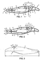
- the figures 1 and 5 each illustrates a configuration of use of the applicator 1, in which the application head 3 projects from the housing 2. In this position, a material can be transferred from the carrier strip 5 to a sheet or other suitable substrate (not shown)
- the protruding tape length outside the housing 2 is limited to a short portion for use configuration. This short protruding portion of the housing 2 is typically bent and is subdivided into an outgoing portion, upstream of the folding zone, guided along the underside 3b of the application head 3, and a re-entrant portion, downstream of the bending zone, guided along the top 3c of the application head 3.
- the band 5 is supported in a known manner per se on the thin end 3a of the application head 3 during the application of material.
- the applicator 1 has a mobility of the application head 3 relative to the housing 2.
- This mobility is on the one hand restricted by guide members 7, and on the other hand controlled by a return device 8 allowing a moving the application head 3 between an advanced position corresponding to the use configuration and a retracted position.
- the return device 8 is for example connected on the one hand to the housing 2 and on the other hand to the application head 3, and allows in configuration of use a displacement of the application head 3 between a proximal position and a position distal from the housing 2.
- the band 5 is guided during sliding with the aid of one or more cylinders or auxiliary rollers R connected to the case 2.
- the return device 8 comprises a first portion fixed to the housing 2 and a second portion fixed to the scroll device 6.
- the displacement of the application head 3 is here linear.
- the two parts of the return device 8 can move away from each other and with a restricted amplitude of movement, interacting with each other within the limits of this displacement so that there is a default position of the second part.
- the return device 8 defines via its portion connected to the housing 2 a reference position x 0 fixed during the displacement of the application head 3.
- the second mobile part of the device 8 moves between two positions x 1 , x 2 spacing relative to the reference position x 0 .
- this part which comprises the magnet M moves towards the position of lesser spacing x 1 when a force is exerted on the application head 3, for example by a substrate on which the application of the material must be carried out.
- the return device 8 then generates a restoring force between its two parts to bias the movable part towards the position x 2 of greater spacing which corresponds to the default position of the application head 3 in the configuration of use of the applicator 1.
- the invention is described above with reference to a restoring force in response to compression or approximation.
- the restoring force may be generated in response to traction.
- the default position of the application head 3 in the use configuration can then correspond to a position of smaller spacing of the movable part of the device 8 relative to the reference position x 0 .
- the restoring force is generated to bias the second part towards the position of smaller spacing.
- this return device 8 is adapted for exerting a restoring force towards the distal position of the application head 3.
- the return device 8 can have different conformations and the force exerted by the return device 8 results from the tendency of the latter to move towards a conformation more stable.
- the force exerted corresponds for example to a magnetic repulsion force between two magnetic members A, M of the return device 8.
- a first member A of these two magnetic members comprising for example one or two magnets 10, 11, is connected to the housing 2, while the second magnetic member M is connected to the moving element 12 which comprises the application head 3 and the scroll device 6.
- the positioning in the housing 2 of the crew 12 can be advantageously controlled by the return device 8 and set by a manually operable portion thereof.
- the crew 12 can be slidably mounted in the housing 2.
- the second magnetic member is for example a magnet M attached to the rear of the scroll device 6 via a support 14a of a supporting structure 14.
- a more complex displacement and / or with a rotation or other adequate movement of the application head 3 can also be obtained, with appropriate guidance inside the housing 2.
- the first magnetic member A is arranged in an actuator assembly with two adjustment positions.
- the actuating member 23 may correspond to a rotating wheel about an axis X perpendicular to the direction of the magnetic field that may be exerted between at least one magnet 10,11 of the actuator assembly A and the magnet M connected to the application head 3.
- the wheel is manually adjustable in rotation and may have an amplitude of rotation of 180 ° for example between the two actuating positions.
- the actuator 23 is manually movable between a first position for actuating the use pattern and a second position for actuating the retracted configuration.
- the actuating member 23 is described as rotating, the displacement of the latter may also correspond to a translation or a combination of a translation and a rotation, for example a helical movement.
- the support 14a defines a housing for receiving the magnet M and has a concave surface adapted to come into contact with a convex surface associated with the magnetic member A connected to the housing 2.
- the housing is disposed remotely to limit the length of the crew 12. Accommodation is thus outside a plane defined by the direction of elongation of the crew 12 and a roller axis.
- the housing 2 can thus have at the rear a curvature that facilitates the gripping of a hand.
- the magnet M connected to the application head 3 has a determined polarity on the opposite side to the application head 3.
- the magnet M has a north pole oriented parallel to the direction of movement of the application head 3 towards the magnetic member A.
- the magnet 10 embedded in the actuator assembly has a north pole vis-à-vis the rear face of the magnet M, the same polarity (north pole).
- the magnets 10, M thus arranged opposite one another generate magnetic field lines of opposite direction. Field lines are thus defined substantially parallel to the direction of movement of the application head 3.
- This repulsion force is for example between 0.5 and 12 Newton, and preferably 1 and 8 Newton between the distal position and the proximal position.
- the return device 8 could implement a spring, including a helical metal spring, replacing the magnets 10, M to exert an elastic restoring force .
- the spring is in this case connected to the housing 2 at one end and the application head 3 at another end.
- the return force would be directly proportional to the stiffness constant of the spring.
- the amplitude of the displacement of the application head 3 between the distal position and the proximal position is for example between 2 and 10 mm, and is preferably about 7 mm.
- the retraction of the application head 3 during a pressure of the applicator 1 against a substrate is thus sufficient to generate a reaction by a jerk when the pressure on the applicator 1 ceases, that is to say at the moment when the user lifts the applicator 1.
- the amplitude d of displacement of the application head 3 between the retracted configuration and the configuration of use can be about 1 mm greater than the amplitude of displacement by amortization.
- the scroll device 6 allows to wind and scroll the band 5 during use.
- the roller or rollers for winding the strip 5 are mounted on the supporting structure 14, perpendicular to the direction of elongation of the crew 12.
- the carrying structure 14 laterally has flat guide walls of the rolled strip 5.
- One of these walls may correspond to an intermediate portion of a part 15 which comprises the support 14a at a rear end and the application head 3 at a front end.
- Guidance sliding of the crew 12 is carried out on the side of the front and rear ends of the crew 12, with the aid of several parallel guiding elements 7 offset laterally with respect to the path of the band 5 in the scrolling device 6.
- the crew 12 slides backwards and the return of the crew 12 forward can be limited by one or more stops 16 of the housing 2, formed for example to a rear end of sliding guide elements 7 located near the opening 4.
- a rod 17 connects the application head 3 to the rest of the crew 12.
- This rod 17 may have fins 18 or other projecting members engaging in a slot defined between two parallel guiding elements 7 integrally formed with the housing 2.
- the application head 3 may have a flattened shape at its free end to facilitate folding the band 5.
- the application head 3 has one or more projections 19 projecting upwards or downwards (perpendicular to the direction of sliding) near the free end of the application head.
- these projections 19 engage against at least one abutment surface 7a formed inside the housing 2.
- the magnet 11 embedded in the actuator assembly has a substantially flat face facing the rear face of the magnet M connected to the application head 3.
- the axis X of rotation of the wheel of the actuator assembly is perpendicular to the displacement of the application head 3 and parallel to the rear face of the magnet M, the magnetic detachment allowed by the rotation of the wheel is made easier than by a tensile force of the magnet 11.
- the scrolling device 6 is associated with guiding means, for example lateral grooves 22 ( figure 1 ) of the housing 2 and the lateral ribs or similar element of the crew 12.
- These guide means are adapted so that in the proximal position of the application head 3 ( figure 2 ), the magnet M comes into almost contact with the magnet 11.
- the projections 19 are then in contact with the corresponding abutment surfaces 7a of the guide elements 7.
- the magnets 11, M can be distant from a short distance of the order of 1 or 2 mm.
- these two magnets 11, M can be contiguous in the retracted configuration of the applicator 1.
- the crew 12 can switch from the use configuration to retracted configuration by simply rotating the wheel, the crew 12 being then maintained in this last configuration.
- the return to the use configuration can be obtained only if the user manipulates the actuating member 23, so as to no longer have a south pole of the magnetic member A facing the north pole of the magnet Mr.
- the magnets 10, 11, M shown are cylindrical with a small diameter, for example less than 15 mm, but of course any form of magnet that can be accommodated inside the case 2 is also suitable.
- the displacement of the magnet 11 as illustrated in FIG. figure 2 by rotating the wheel around the X axis to switch from an attraction mode to a magnetic repulsion mode corresponds to an actuation of the displacement of the application head 3 from a retracted position to a projecting position.
- the displacement of the magnet 10 as illustrated in FIG. figure 1 by rotating the wheel around the X axis to switch from a repulsion mode to a magnetic attraction mode corresponds to an actuation of the displacement of the application head 3 from a projecting position to a retracted position.
- any other one or more magnet arrangement may be used in the actuator assembly.
- the 180 ° rotation of the wheel or similar element makes it possible to go from the retracted configuration to the use configuration.
- the wheel is associated with a hard contact between the housing 2 and the wheel and / or the axis element of the wheel. This makes it possible to maintain the wheel in a fixed position, despite the magnetic repulsion effect experienced by the magnet 10.
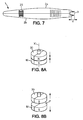
- the wheel may be housed mainly inside the casing 2. As shown in FIG. figure 3 , the gripping portion 24 which exits through an upper opening 25 of the housing 2 is at most only one quarter of the periphery of the actuating wheel.
- the applicator 1 comprises a return device 8 which ensures a permanent biasing of the application head 3 to its distal position.
- the magnets 20, M facing each other face towards one another the same magnetic pole.
- the device 8 is distinguished in that the magnet 20, forming the magnetic member vis-à-vis the magnet M connected to the application head 3, is not provided to actuate the displacement of the application head 3 to a retracted position.
- the magnet 20 is simply held in a fixed position, fixed relative to the housing 2 to exert magnetic repulsion on the magnet M.
- a mechanism for adjusting the repulsion force adjusts the distance between the magnets 20, M.
- a movable member 31 of the adjustment mechanism extends for example transversely in the housing 2 and is integral with the magnet 20 so as to adjust the position of the latter.
- the movable member 31 has here a projecting free end in outside the case. The user can thus reduce or increase the effect of forward thrust exerted on the crew 12.
- This second embodiment is for the rest completely similar to the first embodiment described above.
- the repulsion force can be between the same force values.
- the stop 16 makes it possible to mark the distal position of the application head 3.
- the crew 12 may be identical to that described in the two previous embodiments, with the exception of the rear end.
- the support 14A can be replaced by a support (not shown) which does not extend beyond the rear face F of the magnet M connected to the application head 3.
- the magnet M can have more than one magnetic pole at its rear face F (multipole face).
- the magnet M connected to the application head 3 thus has a bipolar face facing the also bipolar face of a rotating magnet 30 connected to the actuating member 23.
- the rotating magnet 30 has the same face vis-à-vis the magnet M connected to the application head 3, both for the configuration of use as for the retracted configuration.
- This face of the rotating magnet 30 has both outgoing field lines (north pole) and incoming field lines (south pole).
- the rotating magnet 30 has at least two distinct zones angularly offset from each other with respect to the axis X 'of rotation of the magnet 30, corresponding to one pole north and the other at a south pole.
- a retracted configuration similar to that shown in figure 2 is obtained when the rotating magnet 30 has field lines of opposite direction to the field lines of the rear face F of the magnet M.
- the rotating magnet 30 rotates about an axis X 'geometric rotation through the two magnets 30, M.
- the user can operate the transition from one configuration to another by a rotational movement from left to right or from right to left.
- actuation corresponding to a twist (“twist")
- One of the advantages of the invention lies in obtaining a mobility of the application head 3 in the use configuration, which is useful for improving the quality of application of the material on a substrate. Indeed, the return action to the advanced / distal position of the application head 3 allows an easier release of the material (the resulting jolt actively contributes to break the film of adhesive material at the end of the transfer). This also eliminates a mechanism to mechanically lock the configuration of use.
- Another advantage of the invention is that the design of the applicator 1 mobile application head 3 can be simple design.
- the material forming the film or pellets may correspond to at least one white coating material, of another color, or translucent (or even transparent).
- the return device 8 is illustrated in the figures as arranged in the rear part of the applicator 1, other arrangements of the device can be provided: the device 8 can thus occupy on the contrary a position closer to the front end of the rear end. Also, the return device 8 can be offset laterally with respect to a median plane of the supporting structure 14 perpendicular to the strip 5. In alternative embodiments, the device 8 can also be placed mainly outside the housing 2.
- the support 14a can allow a removable attachment of the magnet M.
- the support 14a can be detached from the supporting structure 14. It is then permitted to make a change of the band 5, the rest of the crew 12 defining an interchangeable cartridge that the user can extract from the casing 2.
- the housing 2 may have a manually removable portion with a quick connection to the rest of the housing 2.
- the return function is presented as automatically resulting from actuation of the usage pattern by the actuator 23.
- the magnetic device could also allow a passage of the retracted configuration to the configuration of use, regardless of the actuation of the recall function.
- a first actuating member could serve only to retract or remove the application head 3, while a second optional actuator would allow, in the use configuration, to actuate the function recall.
- Such a second actuator can be used for example, in use configuration, to choose between a first mode with restoring force and magnetic damping and a second mode with immobilization of the application head 3. This second mode can be a preferred mode of use by users particularly accustomed to fixed head applicator devices in use configuration.
Landscapes
- Mechanical Pencils And Projecting And Retracting Systems Therefor, And Multi-System Writing Instruments (AREA)
- Orthopedics, Nursing, And Contraception (AREA)
- Toys (AREA)
- Coating Apparatus (AREA)
Claims (13)
- Manueller Bandapplikator (1), umfassend:- ein ergreifbares Gehäuse (2),- einen Aufbringkopf (3), der bezüglich des Gehäuses beweglich ist und in einer Gebrauchskonfiguration vom Gehäuse (2) vorragt,- ein Tragband (5), das ein Material trägt, das auf ein Substrat aufgebracht werden soll,- eine Laufvorrichtung (6) des Tragbands, die im Gehäuse (2) angeordnet und ausgelegt ist, das Band (5) auf den Aufbringkopf (3) laufen zu lassen, dadurch gekennzeichnet, dass der Applikator (1) ferner eine Rückholvorrichtung (8) umfasst, die einerseits mit dem Gehäuse (2) und andererseits mit dem Aufbringkopf (3) verbunden ist, wobei die Rückholvorrichtung mindestens ein erstes magnetisches Glied (A) und ein zweites magnetisches Glied (M) umfasst, wobei das erste und das zweite magnetische Glied in der Gebrauchskonfiguration so angeordnet sind, dass sie sich im Wesentlichen gegenüberliegen und magnetische Feldlinien mit entgegengesetzter Richtung erzeugen, wobei die Rückholvorrichtung ausgelegt ist,- in der Gebrauchskonfiguration ein Verschieben des Aufbringkopfs (3) zwischen einer proximalen Position und einer distalen Position bezüglich des Gehäuses (2) zu gestatten und- in der Gebrauchskonfiguration eine Rückholkraft auszuüben, die den Aufbringkopf (3) zur distalen Position hin vorspannt.
- Applikator nach Anspruch 1, wobei das zweite magnetische Glied (M) fest mit der Laufvorrichtung (6) verbunden und ausgelegt ist, in der Gebrauchskonfiguration im Wesentlichen parallel zu einer Verschieberichtung des Aufbringkopfs (3) verlaufende Feldlinien zu erzeugen.
- Applikator nach Anspruch 1 oder 2, wobei das Gehäuse (2) Glieder (22) zur translatorischen Führung der Laufvorrichtung (6) aufweist, die so ausgelegt sind, dass das zweite magnetische Glied (M) in der proximalen Position des Aufbringkopfs (3) mit dem ersten magnetischen Glied (A) beinahe in Kontakt kommt.
- Applikator nach einem der Ansprüche 1 bis 3, wobei das erste magnetische Glied (10, 11; 30) mit einem manuellen Betätigungsglied (23) verbunden und ausgelegt ist, eine Drehung des ersten magnetischen Glieds (A) zwischen einer ersten Position, in der der Applikator (1) in der Gebrauchskonfiguration ist, und einer zweiten Position zu steuern, in der der Applikator in einer Konfiguration ist, in der der Aufbringkopf (3) eingezogen ist.
- Applikator nach Anspruch 4, wobei das erste magnetische Glied und das zweite magnetische Glied (M) jeweils eine im Wesentlichen ebene Fläche, die sich gegenüberliegen, in der Gebrauchskonfiguration und der eingezogenen Konfiguration aufweisen.
- Applikator nach Anspruch 5, wobei das erste magnetische Glied (A) zwei gegenüberliegende monopolare Endflächen aufweist, wobei die Drehung des ersten magnetischen Glieds (A) um eine senkrecht zur Verschieberichtung des Aufbringkopfs (3) verlaufende Achse (X) erfolgt.
- Applikator nach Anspruch 5, wobei das zweite magnetische Glied (M) eine im Wesentlichen ebene und mindestens bipolare Fläche (F) gegenüber dem ersten magnetischen Glied (A) aufweist, wobei das erste magnetische Glied eine zur Verschieberichtung des Aufbringkopfs (3) parallel verlaufende Rotationsachse (X') aufweist.
- Applikator nach einem der Ansprüche 1 bis 7, wobei der Aufbringkopf (3) und die Laufvorrichtung (6) fest miteinander verbunden sind und von Führungsgliedern (7, 22) des Gehäuses (2) translatorisch geführt werden, wobei die Rückholvorrichtung (8) ein am Gehäuse (2) befestigtes erstes magnetisches Glied (A) und ein an der Laufvorrichtung (6) befestigtes zweites magnetisches Glied (M) umfasst.
- Applikator nach einem der Ansprüche 4 bis 8, umfassend ein Glied (31) zur Einstellung der Position des ersten magnetischen Glieds (A) in der Gebrauchskonfiguration entlang der Verschieberichtung des Aufbringkopfs (3).
- Applikator nach einem der Ansprüche 1 bis 9, wobei die Weite (d) der Verschiebung des Aufbringkopfs (3) zwischen der distalen Position und der proximalen Position zwischen 2 und 10 mm und vorzugsweise zwischen 6 und 8 mm liegt.
- Applikator nach einem der Ansprüche 1 bis 10, wobei die Rückholkraft zur distalen Position des Aufbringkopfs (3) von 0,5 bis 12 Newton und vorzugsweise von 1 bis 8 Newton zwischen der distalen Position und der proximalen Position beträgt und sich bei Annäherung an die proximale Position sehr bedeutend erhöht.
- Manueller Bandapplikator (1), umfassend:- ein ergreifbares Gehäuse (2),- einen Aufbringkopf (3), der bezüglich des Gehäuses beweglich ist und in der Gebrauchskonfiguration vom Gehäuse (2) vorragt,- ein Tragband (5), das ein Material trägt, das auf ein Substrat aufgebracht werden soll,- eine Laufvorrichtung (6) des Tragbands, die im Gehäuse (2) angeordnet und ausgelegt ist, das Band (5) auf den Aufbringkopf (3) laufen zu lassen, dadurch gekennzeichnet, dass er eine magnetische Vorrichtung umfasst, die einerseits ein mit dem Gehäuse (2) verbundenes erstes magnetisches Glied (A) und andererseits ein mit dem Aufbringkopf (3) verbundenes zweites magnetisches Glied (M) umfasst, wobei die magnetische Vorrichtung ausgelegt ist, eine Verschiebung des Aufbringkopfs (3) von einer in das Gehäuse eingezogenen Position, die einer eingezogenen Konfiguration entspricht, in eine vorragende Position, die der Gebrauchskonfiguration entspricht, in Gang zu setzen.
- Applikator nach Anspruch 12, wobei die magnetische Vorrichtung ein manuelles Betätigungsglied (23) mit zwei Einstellungspositionen umfasst, wobei das erste magnetische Glied (A) mit dem manuellen Betätigungsglied (23) verbunden ist und das zweite magnetische Glied (M) fest mit der Laufvorrichtung (6) verbunden ist.
Applications Claiming Priority (2)
| Application Number | Priority Date | Filing Date | Title |
|---|---|---|---|
| FR0953339A FR2945767B1 (fr) | 2009-05-19 | 2009-05-19 | Applicateur a bande manuel, en particulier correcteur |
| PCT/FR2010/050960 WO2010133799A1 (fr) | 2009-05-19 | 2010-05-18 | Applicateur a bande manuel, en particulier correcteur |
Publications (2)
| Publication Number | Publication Date |
|---|---|
| EP2432720A1 EP2432720A1 (de) | 2012-03-28 |
| EP2432720B1 true EP2432720B1 (de) | 2015-02-25 |
Family
ID=41404314
Family Applications (1)
| Application Number | Title | Priority Date | Filing Date |
|---|---|---|---|
| EP10728779.9A Not-in-force EP2432720B1 (de) | 2009-05-19 | 2010-05-18 | Manueller bandapplikator, insbesondere korrektor |
Country Status (6)
| Country | Link |
|---|---|
| US (1) | US20120073761A1 (de) |
| EP (1) | EP2432720B1 (de) |
| JP (1) | JP5406367B2 (de) |
| CN (1) | CN102803110B (de) |
| FR (1) | FR2945767B1 (de) |
| WO (1) | WO2010133799A1 (de) |
Family Cites Families (12)
| Publication number | Priority date | Publication date | Assignee | Title |
|---|---|---|---|---|
| US2557634A (en) * | 1948-05-21 | 1951-06-19 | Cox Isaac Eugene | Fountain pen |
| US3063419A (en) * | 1956-04-02 | 1962-11-13 | Parker Pen Co | Writing instruments |
| US5507908A (en) * | 1994-06-02 | 1996-04-16 | Chinon Industries, Incorporated | Coloring apparatus |
| JP3330744B2 (ja) * | 1994-09-28 | 2002-09-30 | ゼネラル株式会社 | 転写具 |
| JP3998221B2 (ja) * | 1998-02-16 | 2007-10-24 | 株式会社パイロットコーポレーション | 転写具 |
| EP1201588B1 (de) * | 2000-10-30 | 2004-10-27 | Société BIC | Handgerät zum Aufbringen eines Filmes z.B. eines Klebe-, Schicht- oder gefärbten Material auf ein Substrat |
| JP3106294U (ja) * | 2004-06-30 | 2004-12-16 | ゼネラル株式会社 | カバー機構及び転写具 |
| JP4617430B2 (ja) * | 2005-03-04 | 2011-01-26 | フジコピアン株式会社 | 塗膜転写具 |
| DE102005017558B3 (de) * | 2005-04-16 | 2006-09-28 | Henkel Kgaa | Handgerät zum Übertragen eines Filmes von einem Band auf ein Substrat |
| EP1950160B1 (de) * | 2007-01-23 | 2009-07-22 | Sdi Corporation | Korrekturbandspender mit einziehbarem Auftragskopf |
| JP4591461B2 (ja) * | 2007-03-23 | 2010-12-01 | ぺんてる株式会社 | 出没式塗膜転写具 |
| JP4972787B2 (ja) * | 2007-07-27 | 2012-07-11 | コクヨ株式会社 | 転写具 |
-
2009
- 2009-05-19 FR FR0953339A patent/FR2945767B1/fr not_active Expired - Fee Related
-
2010
- 2010-05-18 CN CN201080033718.0A patent/CN102803110B/zh not_active Expired - Fee Related
- 2010-05-18 WO PCT/FR2010/050960 patent/WO2010133799A1/fr not_active Ceased
- 2010-05-18 JP JP2012511324A patent/JP5406367B2/ja not_active Expired - Fee Related
- 2010-05-18 US US13/320,974 patent/US20120073761A1/en not_active Abandoned
- 2010-05-18 EP EP10728779.9A patent/EP2432720B1/de not_active Not-in-force
Also Published As
| Publication number | Publication date |
|---|---|
| CN102803110A (zh) | 2012-11-28 |
| FR2945767B1 (fr) | 2015-04-10 |
| WO2010133799A1 (fr) | 2010-11-25 |
| FR2945767A1 (fr) | 2010-11-26 |
| JP2012527362A (ja) | 2012-11-08 |
| JP5406367B2 (ja) | 2014-02-05 |
| US20120073761A1 (en) | 2012-03-29 |
| CN102803110B (zh) | 2015-04-22 |
| EP2432720A1 (de) | 2012-03-28 |
Similar Documents
| Publication | Publication Date | Title |
|---|---|---|
| FR2945766A1 (fr) | Instrument d'ecriture a repulsion magnetique | |
| FR2941169A1 (fr) | Outil de transfert de film de revetement | |
| FR2893604A1 (fr) | Outil de transfert de pellicule d'enduit | |
| FR3044783A3 (fr) | Pedale d'embrayage electronique pour vehicule | |
| EP1437260A1 (de) | Auf zwei Achsen rotierbarer Fahrzeugaussenrückspiegel | |
| FR2877607A1 (fr) | Outil de transfert de film de revetement | |
| WO2013114018A1 (fr) | Instrument d'écriture à élément protecteur de pointe rétractable | |
| FR2926489A1 (fr) | Outil de transfert de film de revetement | |
| FR2985250A1 (fr) | Mécanisme d'embrayage variable et distributeur de ruban correcteur dote d'un mécanisme d'embrayage variable | |
| EP1834914A1 (de) | Transportvorrichtung für ein Produkt, das von einem Zuführband kommt | |
| EP3284614A1 (de) | Schreibinstrument, das mit einem durch eine muffe geschützten radiergummi ausgestattet ist | |
| FR2956394A1 (fr) | Outil de transfert d'un film de revetement, tel qu'un ruban correcteur ou un ruban de colle | |
| WO2010133799A1 (fr) | Applicateur a bande manuel, en particulier correcteur | |
| FR3018225A1 (fr) | Systeme de store enrouleur pour un toit ouvrant | |
| FR2917858A1 (fr) | Mecanisme de commande a levier basculant et a configurations multiples, et application | |
| EP1796917B1 (de) | Schreibinstrument | |
| CA2452659C (fr) | Dispositif d'alimentation en papier en rouleau pour machine imprimante | |
| FR2899857A1 (fr) | Dispositif de debrayabilite d'un bras d'essuie-glace pour automobiles | |
| WO2005120862A2 (fr) | Instrument d'ecriture a gomme mobile | |
| EP1905493B1 (de) | Fersenautomatik zur Fixierung für Skischuhe mit feststehendem Körper | |
| EP2414266B1 (de) | Vorrichtung zur erfassung von drehmoment, drucker und betriebsverfahren | |
| EP4576147A1 (de) | Manuelle steuervorrichtung | |
| FR2882936A1 (fr) | Ensemble filet de tennis de table a enrouleur | |
| FR2905723A1 (fr) | Dispositif d'occultation manuel et multi position. | |
| WO2025133535A1 (fr) | Dispositif de commande de manuelle |
Legal Events
| Date | Code | Title | Description |
|---|---|---|---|
| PUAI | Public reference made under article 153(3) epc to a published international application that has entered the european phase |
Free format text: ORIGINAL CODE: 0009012 |
|
| 17P | Request for examination filed |
Effective date: 20111109 |
|
| AK | Designated contracting states |
Kind code of ref document: A1 Designated state(s): AL AT BE BG CH CY CZ DE DK EE ES FI FR GB GR HR HU IE IS IT LI LT LU LV MC MK MT NL NO PL PT RO SE SI SK SM TR |
|
| DAX | Request for extension of the european patent (deleted) | ||
| 17Q | First examination report despatched |
Effective date: 20130621 |
|
| GRAP | Despatch of communication of intention to grant a patent |
Free format text: ORIGINAL CODE: EPIDOSNIGR1 |
|
| INTG | Intention to grant announced |
Effective date: 20141030 |
|
| GRAS | Grant fee paid |
Free format text: ORIGINAL CODE: EPIDOSNIGR3 |
|
| GRAA | (expected) grant |
Free format text: ORIGINAL CODE: 0009210 |
|
| AK | Designated contracting states |
Kind code of ref document: B1 Designated state(s): AL AT BE BG CH CY CZ DE DK EE ES FI FR GB GR HR HU IE IS IT LI LT LU LV MC MK MT NL NO PL PT RO SE SI SK SM TR |
|
| REG | Reference to a national code |
Ref country code: GB Ref legal event code: FG4D Free format text: NOT ENGLISH |
|
| REG | Reference to a national code |
Ref country code: CH Ref legal event code: EP |
|
| REG | Reference to a national code |
Ref country code: IE Ref legal event code: FG4D Free format text: LANGUAGE OF EP DOCUMENT: FRENCH |
|
| REG | Reference to a national code |
Ref country code: DE Ref legal event code: R096 Ref document number: 602010022542 Country of ref document: DE Effective date: 20150409 |
|
| REG | Reference to a national code |
Ref country code: AT Ref legal event code: REF Ref document number: 711761 Country of ref document: AT Kind code of ref document: T Effective date: 20150415 |
|
| REG | Reference to a national code |
Ref country code: FR Ref legal event code: PLFP Year of fee payment: 6 |
|
| REG | Reference to a national code |
Ref country code: NL Ref legal event code: VDEP Effective date: 20150225 |
|
| REG | Reference to a national code |
Ref country code: AT Ref legal event code: MK05 Ref document number: 711761 Country of ref document: AT Kind code of ref document: T Effective date: 20150225 |
|
| REG | Reference to a national code |
Ref country code: LT Ref legal event code: MG4D |
|
| PG25 | Lapsed in a contracting state [announced via postgrant information from national office to epo] |
Ref country code: FI Free format text: LAPSE BECAUSE OF FAILURE TO SUBMIT A TRANSLATION OF THE DESCRIPTION OR TO PAY THE FEE WITHIN THE PRESCRIBED TIME-LIMIT Effective date: 20150225 Ref country code: SE Free format text: LAPSE BECAUSE OF FAILURE TO SUBMIT A TRANSLATION OF THE DESCRIPTION OR TO PAY THE FEE WITHIN THE PRESCRIBED TIME-LIMIT Effective date: 20150225 Ref country code: LT Free format text: LAPSE BECAUSE OF FAILURE TO SUBMIT A TRANSLATION OF THE DESCRIPTION OR TO PAY THE FEE WITHIN THE PRESCRIBED TIME-LIMIT Effective date: 20150225 Ref country code: ES Free format text: LAPSE BECAUSE OF FAILURE TO SUBMIT A TRANSLATION OF THE DESCRIPTION OR TO PAY THE FEE WITHIN THE PRESCRIBED TIME-LIMIT Effective date: 20150225 Ref country code: HR Free format text: LAPSE BECAUSE OF FAILURE TO SUBMIT A TRANSLATION OF THE DESCRIPTION OR TO PAY THE FEE WITHIN THE PRESCRIBED TIME-LIMIT Effective date: 20150225 Ref country code: NO Free format text: LAPSE BECAUSE OF FAILURE TO SUBMIT A TRANSLATION OF THE DESCRIPTION OR TO PAY THE FEE WITHIN THE PRESCRIBED TIME-LIMIT Effective date: 20150525 |
|
| PG25 | Lapsed in a contracting state [announced via postgrant information from national office to epo] |
Ref country code: AT Free format text: LAPSE BECAUSE OF FAILURE TO SUBMIT A TRANSLATION OF THE DESCRIPTION OR TO PAY THE FEE WITHIN THE PRESCRIBED TIME-LIMIT Effective date: 20150225 Ref country code: IS Free format text: LAPSE BECAUSE OF FAILURE TO SUBMIT A TRANSLATION OF THE DESCRIPTION OR TO PAY THE FEE WITHIN THE PRESCRIBED TIME-LIMIT Effective date: 20150625 Ref country code: GR Free format text: LAPSE BECAUSE OF FAILURE TO SUBMIT A TRANSLATION OF THE DESCRIPTION OR TO PAY THE FEE WITHIN THE PRESCRIBED TIME-LIMIT Effective date: 20150526 Ref country code: LV Free format text: LAPSE BECAUSE OF FAILURE TO SUBMIT A TRANSLATION OF THE DESCRIPTION OR TO PAY THE FEE WITHIN THE PRESCRIBED TIME-LIMIT Effective date: 20150225 |
|
| PG25 | Lapsed in a contracting state [announced via postgrant information from national office to epo] |
Ref country code: NL Free format text: LAPSE BECAUSE OF FAILURE TO SUBMIT A TRANSLATION OF THE DESCRIPTION OR TO PAY THE FEE WITHIN THE PRESCRIBED TIME-LIMIT Effective date: 20150225 |
|
| PG25 | Lapsed in a contracting state [announced via postgrant information from national office to epo] |
Ref country code: SK Free format text: LAPSE BECAUSE OF FAILURE TO SUBMIT A TRANSLATION OF THE DESCRIPTION OR TO PAY THE FEE WITHIN THE PRESCRIBED TIME-LIMIT Effective date: 20150225 Ref country code: RO Free format text: LAPSE BECAUSE OF FAILURE TO SUBMIT A TRANSLATION OF THE DESCRIPTION OR TO PAY THE FEE WITHIN THE PRESCRIBED TIME-LIMIT Effective date: 20150225 Ref country code: CZ Free format text: LAPSE BECAUSE OF FAILURE TO SUBMIT A TRANSLATION OF THE DESCRIPTION OR TO PAY THE FEE WITHIN THE PRESCRIBED TIME-LIMIT Effective date: 20150225 Ref country code: DK Free format text: LAPSE BECAUSE OF FAILURE TO SUBMIT A TRANSLATION OF THE DESCRIPTION OR TO PAY THE FEE WITHIN THE PRESCRIBED TIME-LIMIT Effective date: 20150225 Ref country code: EE Free format text: LAPSE BECAUSE OF FAILURE TO SUBMIT A TRANSLATION OF THE DESCRIPTION OR TO PAY THE FEE WITHIN THE PRESCRIBED TIME-LIMIT Effective date: 20150225 |
|
| REG | Reference to a national code |
Ref country code: DE Ref legal event code: R097 Ref document number: 602010022542 Country of ref document: DE |
|
| PG25 | Lapsed in a contracting state [announced via postgrant information from national office to epo] |
Ref country code: PL Free format text: LAPSE BECAUSE OF FAILURE TO SUBMIT A TRANSLATION OF THE DESCRIPTION OR TO PAY THE FEE WITHIN THE PRESCRIBED TIME-LIMIT Effective date: 20150225 |
|
| PG25 | Lapsed in a contracting state [announced via postgrant information from national office to epo] |
Ref country code: IT Free format text: LAPSE BECAUSE OF FAILURE TO SUBMIT A TRANSLATION OF THE DESCRIPTION OR TO PAY THE FEE WITHIN THE PRESCRIBED TIME-LIMIT Effective date: 20150225 |
|
| REG | Reference to a national code |
Ref country code: CH Ref legal event code: PL |
|
| PLBE | No opposition filed within time limit |
Free format text: ORIGINAL CODE: 0009261 |
|
| STAA | Information on the status of an ep patent application or granted ep patent |
Free format text: STATUS: NO OPPOSITION FILED WITHIN TIME LIMIT |
|
| GBPC | Gb: european patent ceased through non-payment of renewal fee |
Effective date: 20150525 |
|
| PG25 | Lapsed in a contracting state [announced via postgrant information from national office to epo] |
Ref country code: CH Free format text: LAPSE BECAUSE OF NON-PAYMENT OF DUE FEES Effective date: 20150531 Ref country code: LI Free format text: LAPSE BECAUSE OF NON-PAYMENT OF DUE FEES Effective date: 20150531 Ref country code: MC Free format text: LAPSE BECAUSE OF FAILURE TO SUBMIT A TRANSLATION OF THE DESCRIPTION OR TO PAY THE FEE WITHIN THE PRESCRIBED TIME-LIMIT Effective date: 20150225 Ref country code: LU Free format text: LAPSE BECAUSE OF FAILURE TO SUBMIT A TRANSLATION OF THE DESCRIPTION OR TO PAY THE FEE WITHIN THE PRESCRIBED TIME-LIMIT Effective date: 20150518 |
|
| 26N | No opposition filed |
Effective date: 20151126 |
|
| REG | Reference to a national code |
Ref country code: IE Ref legal event code: MM4A |
|
| PG25 | Lapsed in a contracting state [announced via postgrant information from national office to epo] |
Ref country code: SI Free format text: LAPSE BECAUSE OF FAILURE TO SUBMIT A TRANSLATION OF THE DESCRIPTION OR TO PAY THE FEE WITHIN THE PRESCRIBED TIME-LIMIT Effective date: 20150225 |
|
| PG25 | Lapsed in a contracting state [announced via postgrant information from national office to epo] |
Ref country code: IE Free format text: LAPSE BECAUSE OF NON-PAYMENT OF DUE FEES Effective date: 20150518 Ref country code: GB Free format text: LAPSE BECAUSE OF NON-PAYMENT OF DUE FEES Effective date: 20150525 |
|
| REG | Reference to a national code |
Ref country code: FR Ref legal event code: PLFP Year of fee payment: 7 |
|
| PGFP | Annual fee paid to national office [announced via postgrant information from national office to epo] |
Ref country code: DE Payment date: 20160527 Year of fee payment: 7 |
|
| PGFP | Annual fee paid to national office [announced via postgrant information from national office to epo] |
Ref country code: FR Payment date: 20160530 Year of fee payment: 7 |
|
| PG25 | Lapsed in a contracting state [announced via postgrant information from national office to epo] |
Ref country code: MT Free format text: LAPSE BECAUSE OF FAILURE TO SUBMIT A TRANSLATION OF THE DESCRIPTION OR TO PAY THE FEE WITHIN THE PRESCRIBED TIME-LIMIT Effective date: 20150225 |
|
| PG25 | Lapsed in a contracting state [announced via postgrant information from national office to epo] |
Ref country code: BG Free format text: LAPSE BECAUSE OF FAILURE TO SUBMIT A TRANSLATION OF THE DESCRIPTION OR TO PAY THE FEE WITHIN THE PRESCRIBED TIME-LIMIT Effective date: 20150225 Ref country code: SM Free format text: LAPSE BECAUSE OF FAILURE TO SUBMIT A TRANSLATION OF THE DESCRIPTION OR TO PAY THE FEE WITHIN THE PRESCRIBED TIME-LIMIT Effective date: 20150225 Ref country code: HU Free format text: LAPSE BECAUSE OF FAILURE TO SUBMIT A TRANSLATION OF THE DESCRIPTION OR TO PAY THE FEE WITHIN THE PRESCRIBED TIME-LIMIT; INVALID AB INITIO Effective date: 20100518 |
|
| PG25 | Lapsed in a contracting state [announced via postgrant information from national office to epo] |
Ref country code: CY Free format text: LAPSE BECAUSE OF FAILURE TO SUBMIT A TRANSLATION OF THE DESCRIPTION OR TO PAY THE FEE WITHIN THE PRESCRIBED TIME-LIMIT Effective date: 20150225 |
|
| PG25 | Lapsed in a contracting state [announced via postgrant information from national office to epo] |
Ref country code: BE Free format text: LAPSE BECAUSE OF NON-PAYMENT OF DUE FEES Effective date: 20150531 |
|
| PG25 | Lapsed in a contracting state [announced via postgrant information from national office to epo] |
Ref country code: TR Free format text: LAPSE BECAUSE OF FAILURE TO SUBMIT A TRANSLATION OF THE DESCRIPTION OR TO PAY THE FEE WITHIN THE PRESCRIBED TIME-LIMIT Effective date: 20150225 |
|
| REG | Reference to a national code |
Ref country code: DE Ref legal event code: R119 Ref document number: 602010022542 Country of ref document: DE |
|
| REG | Reference to a national code |
Ref country code: FR Ref legal event code: ST Effective date: 20180131 |
|
| PG25 | Lapsed in a contracting state [announced via postgrant information from national office to epo] |
Ref country code: DE Free format text: LAPSE BECAUSE OF NON-PAYMENT OF DUE FEES Effective date: 20171201 |
|
| PG25 | Lapsed in a contracting state [announced via postgrant information from national office to epo] |
Ref country code: FR Free format text: LAPSE BECAUSE OF NON-PAYMENT OF DUE FEES Effective date: 20170531 |
|
| PG25 | Lapsed in a contracting state [announced via postgrant information from national office to epo] |
Ref country code: MK Free format text: LAPSE BECAUSE OF FAILURE TO SUBMIT A TRANSLATION OF THE DESCRIPTION OR TO PAY THE FEE WITHIN THE PRESCRIBED TIME-LIMIT Effective date: 20150225 Ref country code: PT Free format text: LAPSE BECAUSE OF FAILURE TO SUBMIT A TRANSLATION OF THE DESCRIPTION OR TO PAY THE FEE WITHIN THE PRESCRIBED TIME-LIMIT Effective date: 20150225 |
|
| PG25 | Lapsed in a contracting state [announced via postgrant information from national office to epo] |
Ref country code: AL Free format text: LAPSE BECAUSE OF FAILURE TO SUBMIT A TRANSLATION OF THE DESCRIPTION OR TO PAY THE FEE WITHIN THE PRESCRIBED TIME-LIMIT Effective date: 20150225 |