EP2431748A1 - Microchip - Google Patents
Microchip Download PDFInfo
- Publication number
- EP2431748A1 EP2431748A1 EP10774773A EP10774773A EP2431748A1 EP 2431748 A1 EP2431748 A1 EP 2431748A1 EP 10774773 A EP10774773 A EP 10774773A EP 10774773 A EP10774773 A EP 10774773A EP 2431748 A1 EP2431748 A1 EP 2431748A1
- Authority
- EP
- European Patent Office
- Prior art keywords
- space
- hole
- resin substrate
- flow channel
- base end
- Prior art date
- Legal status (The legal status is an assumption and is not a legal conclusion. Google has not performed a legal analysis and makes no representation as to the accuracy of the status listed.)
- Granted
Links
Images


Classifications
-
- B—PERFORMING OPERATIONS; TRANSPORTING
- B01—PHYSICAL OR CHEMICAL PROCESSES OR APPARATUS IN GENERAL
- B01L—CHEMICAL OR PHYSICAL LABORATORY APPARATUS FOR GENERAL USE
- B01L3/00—Containers or dishes for laboratory use, e.g. laboratory glassware; Droppers
- B01L3/50—Containers for the purpose of retaining a material to be analysed, e.g. test tubes
- B01L3/502—Containers for the purpose of retaining a material to be analysed, e.g. test tubes with fluid transport, e.g. in multi-compartment structures
- B01L3/5027—Containers for the purpose of retaining a material to be analysed, e.g. test tubes with fluid transport, e.g. in multi-compartment structures by integrated microfluidic structures, i.e. dimensions of channels and chambers are such that surface tension forces are important, e.g. lab-on-a-chip
- B01L3/502707—Containers for the purpose of retaining a material to be analysed, e.g. test tubes with fluid transport, e.g. in multi-compartment structures by integrated microfluidic structures, i.e. dimensions of channels and chambers are such that surface tension forces are important, e.g. lab-on-a-chip characterised by the manufacture of the container or its components
-
- B—PERFORMING OPERATIONS; TRANSPORTING
- B01—PHYSICAL OR CHEMICAL PROCESSES OR APPARATUS IN GENERAL
- B01L—CHEMICAL OR PHYSICAL LABORATORY APPARATUS FOR GENERAL USE
- B01L3/00—Containers or dishes for laboratory use, e.g. laboratory glassware; Droppers
- B01L3/50—Containers for the purpose of retaining a material to be analysed, e.g. test tubes
- B01L3/502—Containers for the purpose of retaining a material to be analysed, e.g. test tubes with fluid transport, e.g. in multi-compartment structures
- B01L3/5027—Containers for the purpose of retaining a material to be analysed, e.g. test tubes with fluid transport, e.g. in multi-compartment structures by integrated microfluidic structures, i.e. dimensions of channels and chambers are such that surface tension forces are important, e.g. lab-on-a-chip
- B01L3/502715—Containers for the purpose of retaining a material to be analysed, e.g. test tubes with fluid transport, e.g. in multi-compartment structures by integrated microfluidic structures, i.e. dimensions of channels and chambers are such that surface tension forces are important, e.g. lab-on-a-chip characterised by interfacing components, e.g. fluidic, electrical, optical or mechanical interfaces
-
- B—PERFORMING OPERATIONS; TRANSPORTING
- B29—WORKING OF PLASTICS; WORKING OF SUBSTANCES IN A PLASTIC STATE IN GENERAL
- B29C—SHAPING OR JOINING OF PLASTICS; SHAPING OF MATERIAL IN A PLASTIC STATE, NOT OTHERWISE PROVIDED FOR; AFTER-TREATMENT OF THE SHAPED PRODUCTS, e.g. REPAIRING
- B29C66/00—General aspects of processes or apparatus for joining preformed parts
- B29C66/01—General aspects dealing with the joint area or with the area to be joined
- B29C66/05—Particular design of joint configurations
- B29C66/10—Particular design of joint configurations particular design of the joint cross-sections
- B29C66/11—Joint cross-sections comprising a single joint-segment, i.e. one of the parts to be joined comprising a single joint-segment in the joint cross-section
- B29C66/112—Single lapped joints
-
- B—PERFORMING OPERATIONS; TRANSPORTING
- B29—WORKING OF PLASTICS; WORKING OF SUBSTANCES IN A PLASTIC STATE IN GENERAL
- B29C—SHAPING OR JOINING OF PLASTICS; SHAPING OF MATERIAL IN A PLASTIC STATE, NOT OTHERWISE PROVIDED FOR; AFTER-TREATMENT OF THE SHAPED PRODUCTS, e.g. REPAIRING
- B29C66/00—General aspects of processes or apparatus for joining preformed parts
- B29C66/01—General aspects dealing with the joint area or with the area to be joined
- B29C66/05—Particular design of joint configurations
- B29C66/10—Particular design of joint configurations particular design of the joint cross-sections
- B29C66/13—Single flanged joints; Fin-type joints; Single hem joints; Edge joints; Interpenetrating fingered joints; Other specific particular designs of joint cross-sections not provided for in groups B29C66/11 - B29C66/12
- B29C66/131—Single flanged joints, i.e. one of the parts to be joined being rigid and flanged in the joint area
-
- B—PERFORMING OPERATIONS; TRANSPORTING
- B29—WORKING OF PLASTICS; WORKING OF SUBSTANCES IN A PLASTIC STATE IN GENERAL
- B29C—SHAPING OR JOINING OF PLASTICS; SHAPING OF MATERIAL IN A PLASTIC STATE, NOT OTHERWISE PROVIDED FOR; AFTER-TREATMENT OF THE SHAPED PRODUCTS, e.g. REPAIRING
- B29C66/00—General aspects of processes or apparatus for joining preformed parts
- B29C66/50—General aspects of joining tubular articles; General aspects of joining long products, i.e. bars or profiled elements; General aspects of joining single elements to tubular articles, hollow articles or bars; General aspects of joining several hollow-preforms to form hollow or tubular articles
- B29C66/51—Joining tubular articles, profiled elements or bars; Joining single elements to tubular articles, hollow articles or bars; Joining several hollow-preforms to form hollow or tubular articles
- B29C66/53—Joining single elements to tubular articles, hollow articles or bars
- B29C66/534—Joining single elements to open ends of tubular or hollow articles or to the ends of bars
- B29C66/5346—Joining single elements to open ends of tubular or hollow articles or to the ends of bars said single elements being substantially flat
-
- B—PERFORMING OPERATIONS; TRANSPORTING
- B29—WORKING OF PLASTICS; WORKING OF SUBSTANCES IN A PLASTIC STATE IN GENERAL
- B29C—SHAPING OR JOINING OF PLASTICS; SHAPING OF MATERIAL IN A PLASTIC STATE, NOT OTHERWISE PROVIDED FOR; AFTER-TREATMENT OF THE SHAPED PRODUCTS, e.g. REPAIRING
- B29C66/00—General aspects of processes or apparatus for joining preformed parts
- B29C66/70—General aspects of processes or apparatus for joining preformed parts characterised by the composition, physical properties or the structure of the material of the parts to be joined; Joining with non-plastics material
- B29C66/73—General aspects of processes or apparatus for joining preformed parts characterised by the composition, physical properties or the structure of the material of the parts to be joined; Joining with non-plastics material characterised by the intensive physical properties of the material of the parts to be joined, by the optical properties of the material of the parts to be joined, by the extensive physical properties of the parts to be joined, by the state of the material of the parts to be joined or by the material of the parts to be joined being a thermoplastic or a thermoset
- B29C66/735—General aspects of processes or apparatus for joining preformed parts characterised by the composition, physical properties or the structure of the material of the parts to be joined; Joining with non-plastics material characterised by the intensive physical properties of the material of the parts to be joined, by the optical properties of the material of the parts to be joined, by the extensive physical properties of the parts to be joined, by the state of the material of the parts to be joined or by the material of the parts to be joined being a thermoplastic or a thermoset characterised by the extensive physical properties of the parts to be joined
- B29C66/7352—Thickness, e.g. very thin
-
- B—PERFORMING OPERATIONS; TRANSPORTING
- B01—PHYSICAL OR CHEMICAL PROCESSES OR APPARATUS IN GENERAL
- B01L—CHEMICAL OR PHYSICAL LABORATORY APPARATUS FOR GENERAL USE
- B01L2200/00—Solutions for specific problems relating to chemical or physical laboratory apparatus
- B01L2200/02—Adapting objects or devices to another
- B01L2200/026—Fluid interfacing between devices or objects, e.g. connectors, inlet details
- B01L2200/027—Fluid interfacing between devices or objects, e.g. connectors, inlet details for microfluidic devices
-
- B—PERFORMING OPERATIONS; TRANSPORTING
- B01—PHYSICAL OR CHEMICAL PROCESSES OR APPARATUS IN GENERAL
- B01L—CHEMICAL OR PHYSICAL LABORATORY APPARATUS FOR GENERAL USE
- B01L2200/00—Solutions for specific problems relating to chemical or physical laboratory apparatus
- B01L2200/06—Fluid handling related problems
- B01L2200/0689—Sealing
-
- B—PERFORMING OPERATIONS; TRANSPORTING
- B01—PHYSICAL OR CHEMICAL PROCESSES OR APPARATUS IN GENERAL
- B01L—CHEMICAL OR PHYSICAL LABORATORY APPARATUS FOR GENERAL USE
- B01L2300/00—Additional constructional details
- B01L2300/04—Closures and closing means
- B01L2300/041—Connecting closures to device or container
- B01L2300/042—Caps; Plugs
-
- B—PERFORMING OPERATIONS; TRANSPORTING
- B01—PHYSICAL OR CHEMICAL PROCESSES OR APPARATUS IN GENERAL
- B01L—CHEMICAL OR PHYSICAL LABORATORY APPARATUS FOR GENERAL USE
- B01L2300/00—Additional constructional details
- B01L2300/08—Geometry, shape and general structure
- B01L2300/0809—Geometry, shape and general structure rectangular shaped
- B01L2300/0816—Cards, e.g. flat sample carriers usually with flow in two horizontal directions
-
- B—PERFORMING OPERATIONS; TRANSPORTING
- B01—PHYSICAL OR CHEMICAL PROCESSES OR APPARATUS IN GENERAL
- B01L—CHEMICAL OR PHYSICAL LABORATORY APPARATUS FOR GENERAL USE
- B01L2300/00—Additional constructional details
- B01L2300/08—Geometry, shape and general structure
- B01L2300/0861—Configuration of multiple channels and/or chambers in a single devices
- B01L2300/0877—Flow chambers
-
- B—PERFORMING OPERATIONS; TRANSPORTING
- B01—PHYSICAL OR CHEMICAL PROCESSES OR APPARATUS IN GENERAL
- B01L—CHEMICAL OR PHYSICAL LABORATORY APPARATUS FOR GENERAL USE
- B01L2300/00—Additional constructional details
- B01L2300/08—Geometry, shape and general structure
- B01L2300/0887—Laminated structure
-
- B—PERFORMING OPERATIONS; TRANSPORTING
- B29—WORKING OF PLASTICS; WORKING OF SUBSTANCES IN A PLASTIC STATE IN GENERAL
- B29C—SHAPING OR JOINING OF PLASTICS; SHAPING OF MATERIAL IN A PLASTIC STATE, NOT OTHERWISE PROVIDED FOR; AFTER-TREATMENT OF THE SHAPED PRODUCTS, e.g. REPAIRING
- B29C65/00—Joining or sealing of preformed parts, e.g. welding of plastics materials; Apparatus therefor
- B29C65/02—Joining or sealing of preformed parts, e.g. welding of plastics materials; Apparatus therefor by heating, with or without pressure
- B29C65/06—Joining or sealing of preformed parts, e.g. welding of plastics materials; Apparatus therefor by heating, with or without pressure using friction, e.g. spin welding
-
- B—PERFORMING OPERATIONS; TRANSPORTING
- B29—WORKING OF PLASTICS; WORKING OF SUBSTANCES IN A PLASTIC STATE IN GENERAL
- B29C—SHAPING OR JOINING OF PLASTICS; SHAPING OF MATERIAL IN A PLASTIC STATE, NOT OTHERWISE PROVIDED FOR; AFTER-TREATMENT OF THE SHAPED PRODUCTS, e.g. REPAIRING
- B29C65/00—Joining or sealing of preformed parts, e.g. welding of plastics materials; Apparatus therefor
- B29C65/02—Joining or sealing of preformed parts, e.g. welding of plastics materials; Apparatus therefor by heating, with or without pressure
- B29C65/08—Joining or sealing of preformed parts, e.g. welding of plastics materials; Apparatus therefor by heating, with or without pressure using ultrasonic vibrations
-
- B—PERFORMING OPERATIONS; TRANSPORTING
- B29—WORKING OF PLASTICS; WORKING OF SUBSTANCES IN A PLASTIC STATE IN GENERAL
- B29C—SHAPING OR JOINING OF PLASTICS; SHAPING OF MATERIAL IN A PLASTIC STATE, NOT OTHERWISE PROVIDED FOR; AFTER-TREATMENT OF THE SHAPED PRODUCTS, e.g. REPAIRING
- B29C65/00—Joining or sealing of preformed parts, e.g. welding of plastics materials; Apparatus therefor
- B29C65/02—Joining or sealing of preformed parts, e.g. welding of plastics materials; Apparatus therefor by heating, with or without pressure
- B29C65/10—Joining or sealing of preformed parts, e.g. welding of plastics materials; Apparatus therefor by heating, with or without pressure using hot gases (e.g. combustion gases) or flames coming in contact with at least one of the parts to be joined
-
- B—PERFORMING OPERATIONS; TRANSPORTING
- B29—WORKING OF PLASTICS; WORKING OF SUBSTANCES IN A PLASTIC STATE IN GENERAL
- B29C—SHAPING OR JOINING OF PLASTICS; SHAPING OF MATERIAL IN A PLASTIC STATE, NOT OTHERWISE PROVIDED FOR; AFTER-TREATMENT OF THE SHAPED PRODUCTS, e.g. REPAIRING
- B29C65/00—Joining or sealing of preformed parts, e.g. welding of plastics materials; Apparatus therefor
- B29C65/02—Joining or sealing of preformed parts, e.g. welding of plastics materials; Apparatus therefor by heating, with or without pressure
- B29C65/14—Joining or sealing of preformed parts, e.g. welding of plastics materials; Apparatus therefor by heating, with or without pressure using wave energy, i.e. electromagnetic radiation, or particle radiation
- B29C65/16—Laser beams
-
- B—PERFORMING OPERATIONS; TRANSPORTING
- B29—WORKING OF PLASTICS; WORKING OF SUBSTANCES IN A PLASTIC STATE IN GENERAL
- B29C—SHAPING OR JOINING OF PLASTICS; SHAPING OF MATERIAL IN A PLASTIC STATE, NOT OTHERWISE PROVIDED FOR; AFTER-TREATMENT OF THE SHAPED PRODUCTS, e.g. REPAIRING
- B29C65/00—Joining or sealing of preformed parts, e.g. welding of plastics materials; Apparatus therefor
- B29C65/02—Joining or sealing of preformed parts, e.g. welding of plastics materials; Apparatus therefor by heating, with or without pressure
- B29C65/18—Joining or sealing of preformed parts, e.g. welding of plastics materials; Apparatus therefor by heating, with or without pressure using heated tools
- B29C65/20—Joining or sealing of preformed parts, e.g. welding of plastics materials; Apparatus therefor by heating, with or without pressure using heated tools with direct contact, e.g. using "mirror"
-
- B—PERFORMING OPERATIONS; TRANSPORTING
- B29—WORKING OF PLASTICS; WORKING OF SUBSTANCES IN A PLASTIC STATE IN GENERAL
- B29C—SHAPING OR JOINING OF PLASTICS; SHAPING OF MATERIAL IN A PLASTIC STATE, NOT OTHERWISE PROVIDED FOR; AFTER-TREATMENT OF THE SHAPED PRODUCTS, e.g. REPAIRING
- B29C65/00—Joining or sealing of preformed parts, e.g. welding of plastics materials; Apparatus therefor
- B29C65/48—Joining or sealing of preformed parts, e.g. welding of plastics materials; Apparatus therefor using adhesives, i.e. using supplementary joining material; solvent bonding
- B29C65/4895—Solvent bonding, i.e. the surfaces of the parts to be joined being treated with solvents, swelling or softening agents, without adhesives
-
- B—PERFORMING OPERATIONS; TRANSPORTING
- B29—WORKING OF PLASTICS; WORKING OF SUBSTANCES IN A PLASTIC STATE IN GENERAL
- B29C—SHAPING OR JOINING OF PLASTICS; SHAPING OF MATERIAL IN A PLASTIC STATE, NOT OTHERWISE PROVIDED FOR; AFTER-TREATMENT OF THE SHAPED PRODUCTS, e.g. REPAIRING
- B29C66/00—General aspects of processes or apparatus for joining preformed parts
- B29C66/70—General aspects of processes or apparatus for joining preformed parts characterised by the composition, physical properties or the structure of the material of the parts to be joined; Joining with non-plastics material
- B29C66/71—General aspects of processes or apparatus for joining preformed parts characterised by the composition, physical properties or the structure of the material of the parts to be joined; Joining with non-plastics material characterised by the composition of the plastics material of the parts to be joined
-
- B—PERFORMING OPERATIONS; TRANSPORTING
- B29—WORKING OF PLASTICS; WORKING OF SUBSTANCES IN A PLASTIC STATE IN GENERAL
- B29C—SHAPING OR JOINING OF PLASTICS; SHAPING OF MATERIAL IN A PLASTIC STATE, NOT OTHERWISE PROVIDED FOR; AFTER-TREATMENT OF THE SHAPED PRODUCTS, e.g. REPAIRING
- B29C66/00—General aspects of processes or apparatus for joining preformed parts
- B29C66/70—General aspects of processes or apparatus for joining preformed parts characterised by the composition, physical properties or the structure of the material of the parts to be joined; Joining with non-plastics material
- B29C66/73—General aspects of processes or apparatus for joining preformed parts characterised by the composition, physical properties or the structure of the material of the parts to be joined; Joining with non-plastics material characterised by the intensive physical properties of the material of the parts to be joined, by the optical properties of the material of the parts to be joined, by the extensive physical properties of the parts to be joined, by the state of the material of the parts to be joined or by the material of the parts to be joined being a thermoplastic or a thermoset
- B29C66/739—General aspects of processes or apparatus for joining preformed parts characterised by the composition, physical properties or the structure of the material of the parts to be joined; Joining with non-plastics material characterised by the intensive physical properties of the material of the parts to be joined, by the optical properties of the material of the parts to be joined, by the extensive physical properties of the parts to be joined, by the state of the material of the parts to be joined or by the material of the parts to be joined being a thermoplastic or a thermoset characterised by the material of the parts to be joined being a thermoplastic or a thermoset
- B29C66/7392—General aspects of processes or apparatus for joining preformed parts characterised by the composition, physical properties or the structure of the material of the parts to be joined; Joining with non-plastics material characterised by the intensive physical properties of the material of the parts to be joined, by the optical properties of the material of the parts to be joined, by the extensive physical properties of the parts to be joined, by the state of the material of the parts to be joined or by the material of the parts to be joined being a thermoplastic or a thermoset characterised by the material of the parts to be joined being a thermoplastic or a thermoset characterised by the material of at least one of the parts being a thermoplastic
- B29C66/73921—General aspects of processes or apparatus for joining preformed parts characterised by the composition, physical properties or the structure of the material of the parts to be joined; Joining with non-plastics material characterised by the intensive physical properties of the material of the parts to be joined, by the optical properties of the material of the parts to be joined, by the extensive physical properties of the parts to be joined, by the state of the material of the parts to be joined or by the material of the parts to be joined being a thermoplastic or a thermoset characterised by the material of the parts to be joined being a thermoplastic or a thermoset characterised by the material of at least one of the parts being a thermoplastic characterised by the materials of both parts being thermoplastics
-
- B—PERFORMING OPERATIONS; TRANSPORTING
- B29—WORKING OF PLASTICS; WORKING OF SUBSTANCES IN A PLASTIC STATE IN GENERAL
- B29L—INDEXING SCHEME ASSOCIATED WITH SUBCLASS B29C, RELATING TO PARTICULAR ARTICLES
- B29L2031/00—Other particular articles
- B29L2031/756—Microarticles, nanoarticles
-
- B—PERFORMING OPERATIONS; TRANSPORTING
- B32—LAYERED PRODUCTS
- B32B—LAYERED PRODUCTS, i.e. PRODUCTS BUILT-UP OF STRATA OF FLAT OR NON-FLAT, e.g. CELLULAR OR HONEYCOMB, FORM
- B32B3/00—Layered products comprising a layer with external or internal discontinuities or unevennesses, or a layer of non-planar form; Layered products having particular features of form
- B32B3/26—Layered products comprising a layer with external or internal discontinuities or unevennesses, or a layer of non-planar form; Layered products having particular features of form characterised by a particular shape of the outline of the cross-section of a continuous layer; characterised by a layer with cavities or internal voids ; characterised by an apertured layer
- B32B3/263—Layered products comprising a layer with external or internal discontinuities or unevennesses, or a layer of non-planar form; Layered products having particular features of form characterised by a particular shape of the outline of the cross-section of a continuous layer; characterised by a layer with cavities or internal voids ; characterised by an apertured layer characterised by a layer having non-uniform thickness
-
- B—PERFORMING OPERATIONS; TRANSPORTING
- B32—LAYERED PRODUCTS
- B32B—LAYERED PRODUCTS, i.e. PRODUCTS BUILT-UP OF STRATA OF FLAT OR NON-FLAT, e.g. CELLULAR OR HONEYCOMB, FORM
- B32B3/00—Layered products comprising a layer with external or internal discontinuities or unevennesses, or a layer of non-planar form; Layered products having particular features of form
- B32B3/26—Layered products comprising a layer with external or internal discontinuities or unevennesses, or a layer of non-planar form; Layered products having particular features of form characterised by a particular shape of the outline of the cross-section of a continuous layer; characterised by a layer with cavities or internal voids ; characterised by an apertured layer
- B32B3/266—Layered products comprising a layer with external or internal discontinuities or unevennesses, or a layer of non-planar form; Layered products having particular features of form characterised by a particular shape of the outline of the cross-section of a continuous layer; characterised by a layer with cavities or internal voids ; characterised by an apertured layer characterised by an apertured layer, the apertures going through the whole thickness of the layer, e.g. expanded metal, perforated layer, slit layer regular cells B32B3/12
-
- B—PERFORMING OPERATIONS; TRANSPORTING
- B32—LAYERED PRODUCTS
- B32B—LAYERED PRODUCTS, i.e. PRODUCTS BUILT-UP OF STRATA OF FLAT OR NON-FLAT, e.g. CELLULAR OR HONEYCOMB, FORM
- B32B3/00—Layered products comprising a layer with external or internal discontinuities or unevennesses, or a layer of non-planar form; Layered products having particular features of form
- B32B3/26—Layered products comprising a layer with external or internal discontinuities or unevennesses, or a layer of non-planar form; Layered products having particular features of form characterised by a particular shape of the outline of the cross-section of a continuous layer; characterised by a layer with cavities or internal voids ; characterised by an apertured layer
- B32B3/30—Layered products comprising a layer with external or internal discontinuities or unevennesses, or a layer of non-planar form; Layered products having particular features of form characterised by a particular shape of the outline of the cross-section of a continuous layer; characterised by a layer with cavities or internal voids ; characterised by an apertured layer characterised by a layer formed with recesses or projections, e.g. hollows, grooves, protuberances, ribs
-
- B—PERFORMING OPERATIONS; TRANSPORTING
- B32—LAYERED PRODUCTS
- B32B—LAYERED PRODUCTS, i.e. PRODUCTS BUILT-UP OF STRATA OF FLAT OR NON-FLAT, e.g. CELLULAR OR HONEYCOMB, FORM
- B32B7/00—Layered products characterised by the relation between layers; Layered products characterised by the relative orientation of features between layers, or by the relative values of a measurable parameter between layers, i.e. products comprising layers having different physical, chemical or physicochemical properties; Layered products characterised by the interconnection of layers
- B32B7/04—Interconnection of layers
-
- Y—GENERAL TAGGING OF NEW TECHNOLOGICAL DEVELOPMENTS; GENERAL TAGGING OF CROSS-SECTIONAL TECHNOLOGIES SPANNING OVER SEVERAL SECTIONS OF THE IPC; TECHNICAL SUBJECTS COVERED BY FORMER USPC CROSS-REFERENCE ART COLLECTIONS [XRACs] AND DIGESTS
- Y10—TECHNICAL SUBJECTS COVERED BY FORMER USPC
- Y10T—TECHNICAL SUBJECTS COVERED BY FORMER US CLASSIFICATION
- Y10T428/00—Stock material or miscellaneous articles
- Y10T428/24—Structurally defined web or sheet [e.g., overall dimension, etc.]
- Y10T428/24273—Structurally defined web or sheet [e.g., overall dimension, etc.] including aperture
- Y10T428/24281—Struck out portion type
- Y10T428/24289—Embedded or interlocked
Definitions
- a through-hole which penetrates in the thickness direction of the resin substrate, is formed. This through-hole is connected to the flow channel groove.
- a resin substrate having a flow channel groove is provided with a cylindrical protrusion surrounding a through-hole in the surface of the opposite side to the surface where the flow channel groove is formed (for example, Patent Document 1). This protrusion is fitted with a tube or a nozzle to introduce a liquid sample into the flow channel groove or to discharge the liquid sample from the flow channel groove.
- the outer diameter of the protrusion 12 is gradually decreased toward the opening direction of the through-hole 13.
- the tipmost portion of the protrusion 12 has a flat face.
- the diameter of the through-hole 13 is constant in the height direction of the protrusion 12.
- the base end 12a of the protrusion 12 and the base end side edge 13a of the through-hole 13 are shown in FIG. 1a and FIG. 2 .
Abstract


Description
- The present invention relates to a joined microchip, and specifically to a microchip having a three-dimensional structure in one of two resin substrates.
- There have been brought into practical use devices referred to as microanalysis chips or n-TAS's (Micro Total Analysis Systems), in which using microfabrication technology, a micro-flow channel and a circuit are formed in silicone or a glass substrate to carry out chemical reaction, separation, or analysis of a liquid sample such as nucleic acid, protein, or blood in a micro space. It is conceivable that these microchips have such advantages that the used amount of a sample or a reagent or the discharge amount of waste liquid is reduced, and small-foot print, portable, and inexpensive system are realized.
- Microchips are produced in such a manner that two members, in which at least one member thereof having been subjected to microfabrication, are bonded together. Conventionally, for microchips, glass substrates are used and various microfabrication methods have been proposed. However, such glass substrates are unsuitable for mass production and exhibit extremely high cost. Therefore, the development of resin microchips, which are inexpensive and disposable, has been desired.
- To produce a resin microchip, a resin substrate having a flow channel groove in the surface and a resin substrate to cover the flow channel groove are joined. Such a resin substrate having a flow channel groove is produce by a method such as an injection molding method, a press molding method, or a mechanical working method. Then, a resin substrate having a flow channel groove in the surface and a resin substrate for covering are joined together in which the flow channel groove is placed inward. Via this joining, the resin substrate for covering functions as the lid (the cover) of the flow channel groove and then a micro- flow channel is formed by the flow channel groove. Thereby, a microchip having such a micro-flow channel groove in the interior is produced. In joining of resin substrates together, there are listed a welding method to pressure-join resin substrates by heating using a heating plate, hot air, a heating roll, ultrasound, vibration, or a laser; an adhesion method to join resin substrates using an adhesive or a solvent; a joining method utilizing adhesion properties ofresin substrates themselves; and a method to join substrates themselves via surface treatment such as plasma treatment for the resin substrates.
- Further, in a resin substrate having a flow channel groove, a through-hole, which penetrates in the thickness direction of the resin substrate, is formed. This through-hole is connected to the flow channel groove. Still further, a resin substrate having a flow channel groove is provided with a cylindrical protrusion surrounding a through-hole in the surface of the opposite side to the surface where the flow channel groove is formed (for example, Patent Document 1). This protrusion is fitted with a tube or a nozzle to introduce a liquid sample into the flow channel groove or to discharge the liquid sample from the flow channel groove.
- As shown in
FIG. 7 , when tworesin substrates 100 and 200 (hereinafter, referred to as "substrates") are joined using any of the above methods, a jig D to nip the 2substrates substrates FIG. 7a . When such 2substrates substrates -
- Patent Document 1: Unexamined Japanese Patent Application Publication No.
2006-234600 - When 2 flat substrates are nipped by a jig, the entire face of the substrates to be brought into contact with the jig is relatively easily allowed to make contact with the jig uniformly. However, as shown in
FIG. 7a , when onesubstrate 100 has a three-dimensional structure such as a protrusion 120, there has been noted such a problem that it is difficult that a jig D is allowed to make contact with theupper face 122 of the protrusion 120 uniformly in the same manner as in the faces of other flat portions. For example, when a jig D is machined to provide a three-dimensional structure, there is generated a machining dimension error of about several tens µm with respect to the design value between the actual dimension af the jig D making contact with theupper face 122 of a protrusion 120 and the actual dimension of the jig D making contact with thelower portion 121 of the protrusion 120. When using a jig D having such a machining dimension error, 2substrates upper face 122 of the protrusion 120 and weakly makes contact with the faces of other flat portions, whereby the pressure P applied to the protrusion 120 exceeds a predetermined value or, in contrast, the case where the jig D weakly makes contact with theupper face 122 of the protrusion 120 and strongly makes contact with the faces of other flat portions, whereby the pressure P applied to the protrusion 120 falls short of a predetermined value. - Further, there has been noted such a problem that when the pressure applied to the protrusion 120 exceeds a predetermined value, the base
end side edge 131 of a through-hole 130 is deformed; aflow channel groove 110 having depth Ta is crushed; and then 2substrates flow channel groove 110. A crushedflow channel groove 110 is shown inFIG. 7b . In contrast, there has been such a problem that when the force applied to theupper face 122 of the protrusion 120 falls short of the predetermined force, an unjoined portion is generated in the periphery of the baseend side edge 131 of the through-hole 130 (immediately below the protrusion 120). An unjoined portion generated in the periphery of the baseend side edge 131 of the through-hole 130 is shown inFIG. 7c . - In a test such as chemical reaction of the above liquid sample, as described above, when a microchip in which 2
substrates flow channel groove 110 or a microchip in which an unjoined portion has been generated in the periphery of the baseend side edge 131 of a through-hole 130 is used, the same result is not always obtained from the same sample, and conditions, resulting in decreased reproducibility. - The present invention is to solve the above problems and an object thereof is to provide a microchip exhibiting excellent reproducibility.
- To solve the above problems, a first embodiment of this invention is a microchip in which a flow channel groove is formed in a surface of at least one of two resin substrates; the two resin substrates are joined with a face facing inward where the flow channel groove is formed; in at least either one of the two resin substrates, a through-hole of an almost circularly cross-sectional shape leading to the flow channel groove from a face of an opposite side to the face where the two resin substrates are joined is formed; and in the face of the opposite side, a protrusion protruding in a thickness direction of the resin substrate provided so as to surround the through-hole is formed, wherein the microchip in which a space having all almost circularly cross-sectional shape concentric with the through-hole and a depth in the same direction as the thickness direction of the resin substrate is formed on a joint face of one of the two resin substrates or the other resin substrate which is the joint face in the case where the protrusion is projected from an almost perpendicular direction to the joint face, and when a base end side edge of the through-hole is projected on the joint face from the almost perpendicular direction, a relationship of φc > φa is satisfied, provided that a diameter of the base end side of the through-hole is designated as φa and a diameter of an end edge side of the space making contact with the joint face is designated as φc.
- A second embodiment of this invention is a microchip according to the first embodiment, having a feature that a relationship of 2.5 × φb > φc is satisfied, provided that the diameter of the base end side of the protrusion in the case where the base end of the protrusion is projected on the joint face from the almost perpendicular direction is designated as φb.
- A third embodiment of this invention is a microchip according to the second embodiment, having a feature that a relationship of φb ≥ φc is satisfied.
- A fourth embodiment of this invention is a microchip according to any of the first - third embodiments, having a feature that the space is formed in the joint face of the resin substrates in which the flow channel groove has been formed in one of the two resin substrates and the space has a depth so as for a clearance to remain between the base end side edge of the through-hole and the joint face even when the two resin substrates is joined.
- A fifth embodiment of this invention is a microchip according to the fourth embodiments having a feature that the relationship of Ta ≤ Tc ≤ T/2 is satisfied, provided that the depth of the space designated as Tc, the thickness of the resin substrate designated as T, and the depth of the flow channel groove are designated as Ta, respectively.
- A sixth embodiment of this invention is a microchip according to the fourth embodiment, having a feature that the space has a peripheral wall face slanting from the end edge side of the space toward the base end side edge of the through-hole.
- A seventh embodiment of this invention is a microchip according to the fourth embodiment, having a feature that the space has a peripheral wall face slanting from the end edge side of the space toward a tip side edge of the through-hole.
- The first embodiment of this invention makes it possible that in the case where one resin substrate has a protrusion, when substrates are joined together, a flow channel groove is maintained to have a desired shape; an unjoined portion is prevented from occurring; and reproducibility is enhanced.
- The second and third embodiments of this invention make it possible that reproducibility is further enhanced.
- The fourth embodiment of this invention makes it possible that when substrates are joined together, a flow channel groove is maintained to have a predetermined shape.
- The fifth - seventh embodiments of this invention make it possible that when substrates are joined together, a flow channel groove is further maintained to have a predetermined shape.
-
-
FIGS. 1a - 1c are cross-sectional views in the case where the microchip according to the first embodiment of this invention is cut along the center of a through-hole and views in which the shapes of the spaces each are allowed to differ; -
FIG. 2a is a cross-sectional view of a production apparatus of a microchip;FIG. 2b of a b-b line cross-sectional view in the case A; andFIG. 2c is a c-c line cross-sectional view in the case A; -
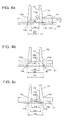
FIGS. 3a - 3c are cross-sectional views in the case where the microchip according to the second embodiment of this invention is cut along the center of a through-hole and views in which the shapes of the spaces each are allowed to differ; -
FIGS. 4a - 4c are cross-sectional views in the case where the microchip according to the third embodiment of this invention is cut along the center of a through-hole and views in which the shapes of the spaces each are allowed to differ; -
FIGS. 5a and 5b are cross-sectional views in the case where the microchip according to the fourth embodiment of this invention is cut along the center of a through-hole and views in which the shapes of the spaces each are allowed to differ; -
FIG. 6 is a figure tabulating the test results of microchips; and -
FIG. 7 is a cross-sectional view of a production apparatus of a microchip according to a conventional example. - The microchip according to the first embodiment af this invention will now be described with reference to
FIG. 1 andFIG. 2 .FIGS. 1a - 1c are cross-sectional views in the case where the microchip according to the first embodiment of this invention is cut along the center of a through-hole.FIG. 2a is a cross-sectional view of a production apparatus of a microchip;FIG. 2b of a b-b line cross-sectional view in the case A; andFIG. 2c is a c-c line cross-sectional view in the case A. - The microchip of this embodiment incorporates a
resin substrate 10 and aresin substrate 20. In the surface of theresin substrate 10, aflow channel groove 11 is formed. Further, theresin substrate 20 serving as the joint counterpart of theresin substrate 10 is a flat plate substrate, and those having a sheet shape or a film shape are used. Then, the face where theflow channel groove 11 is formed is placed inward to join theresin substrate 10 and theresin substrate 20. Thereby, theresin substrate 20 functions as the lid (the cover) of theflow channel groove 11 and then a micro-flow channel is formed by theflow channel groove 11 to produce a microchip having a micro-flow channel in the interior formed by aflow channel groove 11. - In the
resin substrate 10, a through-hole 13 penetrating in the thickness direction of the substrate is formed. This through-hole 13 makes contact with theflow channel groove 11 and leads to theflow channel groove 11 from the face of the opposite side to the joint face of theresin substrate 10 and theresin substrate 20. Herein, "the joint face" refers to at least either of the face of aresin substrate 10 in which aflow channel groove 11 is formed and the face of aresin substrate 20 joined to the face of theresin substrate 10. When theresin substrate 10 and theresin substrate 20 are joined, an opening to connect the flow channel groove to the outside is formed. Since the through-hole 13 leads to theflow channel groove 11, the opening formed by the through-hole 13 leads to the micro-flow channel. The opening (the through-hole 13) is a hole to introduce, store, and discharge gel, a liquid sample, or a buffer solution. The opening (the through-hole 13) is connected to a tube or nozzle provided for an analyzer and then via the tube or nozzle, gel, a liquid sample, or a buffer solution is introduced into the micro-flow channel or discharged from theflow channel groove 11. - Further, in the
resin substrate 10, in the surface of the opposite side to the surface where aflow channel groove 11 is formed, a concavo-convex member is provided. For example, as shown inFIG. 1a , theresin substrate 10 is provided with aprotrusion 12 of a circular truncated cone shape in the surface of the opposite side to the surface where aflow channel groove 11 is formed. Thisprotrusion 12 is protruded in the thickness direction of theresin substrate 10 and provided so as to surround the through-hole 13. Herein, aprotrusion 12 is provided integrally with theresin substrate 10 but may be molded as a separate member to be joined to theresin substrate 10. Thisprotrusion 12 is fitted with a tube or nozzle to introduce or discharge a liquid sample. Incidentally, the cross-sectional shape of theprotrusion 12 shown inFIG. 1a is a circular truncated cone, which is just one example, and may be a cylinder, rectangular cylinder, circular truncated cone, or truncated pyramid. - The outline shape of the
resin substrate 10 needs only to be a shape which is easy to handle and analyze, being preferably square or rectangular. As one example, a size of 10 mm square - 200 mm square is employable. Further, a size of 10 mm square - 100 mm square is employable. The inner diameter of the through-hole 13 needs only to be suitable for the analysis method and the analyzer and to be, for example, about 2 mm. - With regard to the shape of a micro-flow channel, in view of the reduction of the used amount of an analysis sample and a reagent, the production accuracy of a molding die, transfer perfomance, and releasability, both the width and the depth preferably fall within the range of 10 µm - 200 pi,4 being, however, not specifically limited. Further, the width and the depth of the
flow channel groove 11 need only to be determined depending on the intended use of a microchip. Herein, the shape of the cross-section of theflow channel groove 11 may be a rectangular shape or a curved surface. - The plate thickness of the of the
resin substrate 10 in which aflow channel groove 11 has been formed is preferably 0.2 mm - 5 mm, more preferably 0.5 mm - 2 mm in view of moldability. The plate thickness of theresin substrate 20 functioning as the lid (the cover) to cover theflow channel groove 11 is preferably 0.2 mm - 5 mm, more preferably 0.5 mm - 2 mm in view of moldability. Further, when noflow channel groove 11 is formed in theresin substrate 20 functioning as the lid (the cover), instead of the plate member, a film (a sheet member) is usable. In this case, the thickness of the film is preferably 30 µm - 300 µm, more preferably 50 µm - 150 µm. - In this embodiment, the outer diameter of the
protrusion 12 is gradually decreased toward the opening direction of the through-hole 13. The tipmost portion of theprotrusion 12 has a flat face. Further, the diameter of the through-hole 13 is constant in the height direction of theprotrusion 12. Thebase end 12a of theprotrusion 12 and the baseend side edge 13a of the through-hole 13 are shown inFIG. 1a andFIG. 2 . - The diameter of the base
end side edge 13a side of the through-hole 13 in the case where the baseend side edge 13a of the through-hole 13 is projected on the joint face from the direction perpendicular to the joint face is designated as φa. Further, the diameter of thebase end 12a side of theprotrusion 12 in the case where thebase end 12a of theprotrusion 12 is projected on the joint face from the direction perpendicular to the joint face is designated as φb. The baseend side edge 13b of the through-hole 13 when projected and thebase end 12b of theprotrusion 12 when projected are shown inFIG. 1a . - The through-
hole 13 serving as an injection hole is a liquid accumulating section to feed an electrophoresis buffer solution, a migration liquid containing a separation medium such as a molecular sieving polymer, and a sample liquid containing an analysis substance, and at least one hole needs to be formed so as to penetrate in the plate thickness direction. The size of the injection hole is not specifically limited ifbeing a size enabling to inject a migration liquid and a sample liquid. The inner diameter is set to be preferably 0.5 -10 mm, more preferably 1 - 5 mm from the viewpoint of the injection operation. - The through-
hole 13 serving as a discharging hole is a liquid accumulating section to discharge an electrophoresis buffer solution, a migration liquid containing a separation medium such as a molecular sieving polymer, and a sample liquid containing an analysis substance, and at least one hole needs to be formed so as to penetrate in the plate thickness direction or not to penetrate therein. The size of the discharging hole is not specifically limited if being a size enabling to adequately discharge a migration liquid and a sample liquid. The inner diameter is set to be preferably 1-10 mm. more preferably 2 - 5 mm from the viewpoint of the injection operation. - A
space 14 having an almost circularly cross-sectional shape concentric with the through-hole 13 and a depth in the same direction as the thickness direction of aresin substrate 10 is formed in the join face in the case where thebase end 12a of theprotrusion 12 is projected on the joint face from the direction almost perpendicular to the face where tworesin substrates space 14 needs only to be provided in at least either of the joint face of theresin substrate 10 side and the joint face of theresin substrate 20 side. Aspace 14 having been formed in the joint face of theresin substrate 10 side, theend edge 14a of thespace 14 making contact with the joint face, and the diameter φc of theend edge 14a side of thespace 14 are shown inFIG. 1a . - The diameter of φc of the
end edge 14a side of thespace 14 is not specifically limited if the relationship of φb > φb is satisfied. The relationship of 2.5 × φb > φc is preferably satisfied and the relationship of φb ≥ φc is more preferably satisfied. Aspace 14 satisfying the relationship of φb = φc is shown inFIG. 1a . Aspace 14 satisfying the relationship of 2.5 × φb > φc > φb is shown inFIG. 1b . A space satisfying the relationship of φb > φc > φa is shown inFIG. 1c . - Even when two
resin substrates space 14 has a depth so as for a clearance to remain between the baseend side edge 13 a of the through-hole 13 and the joint face. When the deformation amount (the deformation amount of the plate thickness direction of a resin substrate) of the baseend side edge 13a of the through-hole 13 in the case where joining has been carried out is designated as δ and the depth of thespace 14 is designated as Tc, the depth Tc of thespace 14 is not specifically limited if the relationship of Tc >δ is satisfied. However, when the plate thickness of theresin substrate 10 is designated as T and the depth of theflow channel groove 11 is designated as Ta, the relationship of Ta ≤ Tc ≤ T/2 is preferably satisfied from the viewpoint of prevention of the strength decrease of theprotrusion 12. The relationship of Ta = Tc is more preferably satisfied from the viewpoint of the ease of molding of theresin substrate 10. - The plate thickness T of the
resin substrate 10, the depth Ta of theflow channel groove 11, and the depth Tc of thespace 14 are shown inFIG. 1a andFIG. 2 . Herein, the depth Tc of thespace 14 satisfying the above relationship is the same as in thespaces 14 each having different diameter shown inFIGS. 1b and 1c . - A material used for the
resin substrates - In view of productivity, for the
resin substrates nylon 6, nylon 66, polyvinyl acetate, polyvinylidene chloride, polypropylene, polyisoprene, polyethylene, polydimethylsiloxane, and cyclic polyolefin are preferably used. Polymethyl methacrylate and cyclic polyolefin are more preferably used. - Herein, for the
resin substrates 10 and theresin substrate 20, the same material may be used or different materials may be used. Further, for aresin substrate 20 in which no flow channel groove is formed, a thermally curable resin or a UV curable resin may be used, as well as a thermoplastic resin. As the thermally curable resin, polymethylsiloxane is preferably used. - A
resin substrate 10 and aresin substrate 20 can be produced by a method such as an extrusion molding method, a T die molding method, an inflation molding method, a calender molding method, an injection molding method, a press molding method, or a mechanical working method. For example, using an injection molding method, a flow channel groove and a protrusion may be formed in the surface of a resin substrate, or using a mechanical molding method, a flow channel groove and a protrusion may be formed in the surface of a resin substrate. - A film-shaped
resin substrate 20 used in the present embodiment is a member having an electrode (not shown), and needs to be joined to the face in which aflow channel groove 11 of a plate-shapedresin substrate 10 is formed in order to form a micro-flow channel. Herein, sample analysis via electrophoresis is assumed and then a configuration in which a film-shapedresin substrate 20 is provided with an electrode is described. Such an electrode may be provided on the side of theresin substrate 10 or a configuration in which an electrode is introduced from the through hale 13 is employable. Further, when no sample analysis via electrophoresis is conducted, of course, no electrode may be provided. - Next, joining of a
resin substrate 10 and aresin substrate 20 will be described with reference toFIG. 2. FIG. 2 is a view showingresin substrates space 14 shown inFIG. 1a satisfying the relationship of φb = φc and a jig D. - A
resin substrate 10 and aresin substrate 20 are joined by a joining method according to the conventional technique. For example, using a heating plate, hot air, a heating roll, ultrasound, vibration, or a laser, aresin substrate 10 and aresin substrate 20 are pressure-joined by heating. Alternatively, using an adhesive or solvent, aresin substrate 10 and aresin substrate 20 may be joined. However, when the flow channel diameter is varied by such an adhesive or solvent, the reproducibility of analysis is occasionally decreased, and therefor, a configuration in which pressure-joining via heating is carried out is preferable. - On joining of
resin substrates base end 12a of theprotrusion 12 of theresin substrate 10 is allowed to be a border, and then a jig D is brought into contact with the surface of theresin substrate 10 of the outside from thebase end 12a (on the opposite side to the center of the protrusion 12). When such a manner is employed, the jig D does not make contact with theprotrusion 12. - The
base end 12a of aprotrusion 12 serving as the border and a clearance S provided between the jig D and the upper face (the tipmost portion) of theprotrusion 12 are shown inFIG. 2a The jig D needs only to make contact with a flat face portion other than theprotrusion 12. Therefore, theprotrusion 12 needs not to be pressed by the jig D. Thereby, even when a working accuracy error is generated, theprotrusion 12 can be prevented from deforming, and deformation of the flow channel caused by theprotrusion 12 pushed in the adhesion face direction can be prevented. - In the conventional technique, since a jig D strongly makes contact with a protrusion 120, by pressure P exceeding a predetermined value applied to the protrusion 120, as shown in
FIG. 7b , the deformation amount δ of the baseend side edge 13a of the through-hole 130 becomes almost the same value as the depth of theflow channel groove 110, whereby it has been possible that theflow channel groove 110 is crushed. However, in this embodiment, since the jig D does not make contact with theprotrusion 12, the deformation amount δ of the baseend side edge 13a of the through-hole 13 can be allowed to be a minimal value with respect to the depth of theflow channel groove 11. Therefore, whenresin substrates flow channel groove 11 is not crushed by such a deformed baseend side edge 13a of the through-hole 13. - Further, in the conventional technique, since a jig D weakly makes contact with or makes no contact with the protrusion 120, there has been a possibility such that by pressure P falling short of a predetermined value applied to the protrusion 120, as shown in
FIG. 7c , an unjoined portion is generated in the periphery of baseend side edge 131 of the through-hole 130. However, in this embodiment, the presence of aspace 14 makes it possible that by the pressure having been applied to the flat portion, a predetermined pressure P can also be applied to the pez-iphery of the baseend side edge 131 of the through-hole 130 by the jig D. Thereby, occurrence of an unjoined portion can be prevented. - For details, since a jig D makes contact with the
base end 12a of theprotrusion 12 of aresin substrate 10 so as to apply a predetermined pressure P, thebase end 12b of theprotrusion 12 in the case where thebase end 12a of theprotrusion 12 is projected on the joint face is joined to aresin substrate 20. This fact makes it possible that the diameter φb of thebase end 12b side of theprotrusion 12 satisfies the relationship of φb = φc with the diameter φc of theend edge 14a of thespace 14. Thereby, theend edge 14a of thespace 14 is joined to theresin substrate 20 and then occurrence of an unjoined portion can be prevented. Thebase end 12a of theprotrusion 12 of aresin substrate 10 with which a jig D makes contact so as to apply a predetermined pressure P is shown inFIGS. 2b and 2c . - In the above description, joining of a
resin substrate 10 having aspace 14 shown inFIG. 1a satisfying the relationship of φb = φc and aresin substrate 20 has been described. - Next, description will be made on joining of a
resin substrate 10 having aspace 14 shown inFIG. 1b satisfying the relationship of 2.5 × φb > φc and aresin substrate 20 and joining of aresin substrate 10 having aspace 14 shown inFIG. 1c satisfying the relationship of φc > φa and aresin substrate 20. - As shown in
FIG. 1b , in the case of joining of aresin substrate 10 having aspace 14 satisfying the relationship of 2.5 × φb > φc and aresin substrate 20, a jig D may be pressed even to the outer circumference of thebase end 12a of theprotrusion 12 or may be pressed so as to make contact with the surface of theresin substrate 10 corresponding to the outside from theend edge 14a of thespace 14. - The
end edge 14a of thespace 14 is located outside thebase end 12a of theprotrusion 12, and thereby since pressure is adequately applied by the jig D even to theend edge 14a, theend edge 14a of thespace 14 is joined to theresin substrate 20 and then occurrence of an unjoined portion can be prevented. Further, it is preferable that φc being the diameter of theend edge 14a of thespace 14 be less than 2.5 times φb being the diameter of the baseend side edge 13a of the through-hole 13, since even in the case where pressure is applied by the jig D even to thebase end 12a of theprotrusion 12, joining can be certainly carried out with no deformation of theflow channel groove 11. - Further, in the case of joining of a
resin substrate 10 having aspace 14 shown inFIG. 1c satisfying the relationship of φb > φc > φa and aresin substrate 20, the relationship of a jig D and theresin substrates resin substrate 10 having aspace 14 shown inFIG. 1a satisfying the relationship of φb = φc and aresin substrate 20. It is preferable that thebase end 12a of theprotrusion 12 be allowed to be the border to bring the jig D into contact with the surface of theresin substrate 10 corresponding to the outside from thebase end 12a. - The jig D makes contact with the
base end 12a of theprotrusion 12 so as to apply a predetermined pressure P, whereby theend edge 14a of thespace 14 is also applied with at least a requisite minimum pressure. Thereby, theend edge 14a of thespace 14 is joined to theresin substrate 20 and then occurrence of an unjoined portion can be prevented. In order to produce the effects of this invention, the relationship of φc > φa needs only to be satisfied. However, to certainly carry out joining ranging to theend edge 14a of thespace 14, in the case of φb > φc > φa, the relationship of φc ≥ φa + (φb - φa)/2 is more preferably satisfied. This range makes it possible to apply suitable pressure to theend edge 14a of thespace 14. - A microchip according to the second embodiment of this invention will now be described with reference to
FIG. 3. FIGS. 3a - 3c are cross-sectional views in the case where a microchip is cut along the center of the through-hole and views in which the shapes of the spaces each are allowed to differ. - Points in which the constitution of the microchip according to the second embodiment differs from that of the first embodiment will be mainly described. Description on the same points as in the first embodiment will be omitted. In the second embodiment, a
space 14 is provided for aresin substrate 20 functioning as the lid (the cover) to cover theflow channel groove 11. - The diameter φc of the
end edge 14a side of thespace 14 is not specifically limited if the relationship of φc > φa is satisfied. However, the relationship of 2.5 × φb > φc is preferably satisfied. The relationship of φb ≥ φc is more preferably satisfied. Aspace 14 satisfying the relationship of φb = φc is shown inFIG. 3 a. Aspace 14 satisfying the relationship of 2.5 × φb > φc > φb is shown inFIG. 3b . Aspace 14 satisfying the relationship of φb > φc > φa is shown inFIG. 3c . - The
space 14 has a depth so as for a clearance to remain between the baseend side edge 13a a of the through-hole 13 and the joint face even when tworesin substrates end side edge 13a of the througli-hole 13 in the case where joining has been carried out is designated as δ and the depth of thespace 14 is designated as Tc, the depth Tc of thespace 14 is not specifically limited if the relationship of Tc> δ is satisfied. However, when the plate thickness of theresin substrate 20 is designated as T, the relationship of Tc ≤ T/2 is preferably satisfied from the viewpoint of prevention of the strength decrease of theresin substrate 20. The plate thickness T of theresin substrate 20 and the depth Tc of thespace 14 are shown inFIG. 3a , Herein, the depth Tc of aspace 14 satisfying the above relationships is the same as in thespaces 14 differing in diameter each shown inFIGS. 3b and 3c . - On joining of
resin substrates base end 12a of theprotrusion 12 of theresin substrate 10 is allowed to be a border, and then a jig D is brought into contact with the surface of theresin substrate 10 of the outside from thebase end 12a. Therefore, the jig makes no contact with theprotrusion 12. Since the jig D makes no contact with theprotrusion 12, the deformation amount δ of the baseend side edge 13 a of the through-hole 13 is a minimal value with respect to the depth Ta of theflow channel groove 11. Therefore, on joining of theresin substrates flow channel groove 11 is not crushed by a deformed baseend side edge 13a of the through-hole 13. Further, theend edge 14a of thespace 14 is joined to theresin substrate 20 and then occurrence of an unjoined portion can be prevented. - Incidentally, in the case of joining of a
resin substrate 10 having aspace 14 shown inFIG. 3b satisfying the relationship of 2.5 × φb > φc and aresin substrate 20, a jig D may be pressed even to the outer circumference of thebase end 12a of theprotrusion 12 or may be pressed so as to make contact with the surface of theresin substrate 10 corresponding to the outside from theend edge 14a of thespace 14. - A microchip according to the third embodiment of this invention will now be described with reference to
FIG. 4. FIGS. 4a - 4c are cross-sectional views in the case where a microchip is cut along the center of the through-hole and views in which the shapes of the spaces each are allowed to differ. - Points in which the constitution of the microchip according to the third embodiment differs from that of the first embodiment will be mainly described. Description on the same points as in the first embodiment will be omitted, In the third embodiment, a
space 14 is provided for aresin substrate 20 in which aflow channel groove 11 is formed. - The
space 14 has aperipheral wall face 14b slanting from theend edge 14a side of thespace 14 toward the baseend side edge 13a of the through-hole 13. The diameter of the baseend side edge 13b of the through-hole 13 in the case where the baseend side edge 13a of the through-hole 13 is projected on the joint face is designated as φa. And, when the diameter of theend edge 14a side of the space 1.4 making contact with the joint face is designated as φc, the relationship of φc >φa is satisfied. Further, when the diameter of thebase end 12b of theprotrusion 12 in the case where thebase end 12a of theprotrusion 12 is projected on the joint face is designated as φb, the relationship of φb > φc is satisfied. From the above description, the diameter φc ofend edge 14a side of thespace 14 satisfies the relationship of φb ≥ φc > φa. Aspace 14 satisfying the relationship of φb = φc is shown inFIG. 4a . Aspace 14 satisfying the relationship of φb > φc, > φa is shown inFIG. 4b . - When the plate thickness of the
resin substrate 10 is designated as T, the depth of thespace 14 is designated as Tc, and the depth of theflow channel groove 11 is designated as Ta, respectively, thespace 14 preferably maintains the relationship of Ta < Tc ≤ T from the viewpoint of prevention of the strength decrease of theresin substrate 20.Spaces 14 satisfying the relationship of Tc = T are shown inFIGS. 4a - 4c . Herein, the depth Tc of thespace 14 satisfying the above relationship is the same as in thespaces 14 differing in diameter each shown inFIGS. 4b and 4c . - A microchip according to the fourth embodiment ofthis invention will now be described with reference to
FIG. 5. FIGS. 5a and 5b are cross-sectional views in the case where a microchip is cut along the center af the through-hole and views in which the shapes of the spaces each are allowed to differ. - Points in which the constitution of the microchip according to the fourth embodiment differs from that of the first embodiment will be mainly described. Description on the same points as in the first embodiment will be omitted. In the fourth embodiment, a
space 14 is provided for aresin substrate 20 in which aflow channel groove 11 is formed. - The
space 14 has aperipheral wall face 14b slanting from theend edge 14a side of thespace 14 toward thetip side edge 13c of the throughhole 13. In this case, thetip side edge 13c of the through-hole 13 is also the baseend side edge 13a of the through-hole 13. Therefore, the diameter of the baseend side edge 13b side of the through-hole 13 in the case where thetip side edge 13c of the through-hole 13 is projected on the joint face is designated as φa. - When the diameter of the
end edge 14a side of thespace 14 making contact with the joint face is designated as φc, the relationship of φc > φa is satisfied. Further, the diameter of thebase end 12a side of theprotrusion 12 in the case where thebase end 12a of theprotrusion 12 is projected on the joint face is designated as φb, the relationship of φb ≥ φc is satisfied. From the above description, the diameter φc of theend edge 14a side of thespace 14 satisfies the relationship of φb ≥ φc > φa. - The
space 14 preferably satisfies the relationship of φb ≥ φc from the viewpoint of prevention of the strength decrease of theresin substrate 20. Aspace 14 satisfying the relationship of φb is shown inFIG. 5a . Further, a space satisfying the relationship of φb > φc > φa is shown inFIG. 5b . - The plate thickness of the
resin substrate 10 is designated as T, the depth of thespace 14 is designated as Tc, and the depth of the through-hole is designated as Td, respectively, thespace 14 satisfies the relationship of T < Tc ≤ Td .Spaces 14 satisfying the relationship of Tc = Td are shown inFIGS. 5a and 5b . - Specific examples of the above embodiments will now be described.
- Using an injection molding machine, an acrylic resin (ACRYPLEN, produced by Mitsubishi Rayon Co., Ltd.) of a transparent resin material was molded to produce a resin substrate of the flow channel side in which a plurality of flow channel grooves and a plurality of through-holes and protrusions were formed. This resin substrate of the flow channel side corresponds to one example of the
resin substrates 10 in the above embodiments in which aflow channel groove 11, aprotrusion 12, and a through-hole 13 are formed. - The dimension of the resin substrate of the flow channel side is listed below.
- Length of one side = 50 mm
- Thickness = mm
- Width and depth of the
flow channel groove 11= 50 µm - Further, using an acrylic resin as a transparent material, a resin substrate of the cover side was produced in which the thickness of the substrate was 75 µm and the length of one side was 50 mm. This resin substrate of the cover side corresponds to the
resin substrate 20 in the above embodiments. - Subsequently, the surface in which the flow channel grooves were formed was place inward to stack the resin substrate of the flow channel side and the resin substrate of the cover side. In this state, the two resin substrates were nipped by a jig D and then a pressure of 1 kg/cm2 was applied with heating at 90 °C, followed by being kept for 1 minute to produce a microchip.
- On joining of the
resin substrates base end 12a of theprotrusion 12 was allowed to be the border and the jig D was brought into contact with the surface of the outside from thebase end 12a (on the opposite side to the center of the protrusion 12). Therefore, the jig makes no contact with theprotrusions 12. This joining method is the same as for produced microchips according to Example 1 - Example 6 and Comparative Example 1. - Resin substrates of the flow channel side in which the value of each
space 14 was changed were produced to produce microchips. The results of Example 1 - Example 6 and Comparative Example 1 are shown in the table ofFIG. 6 . Herein, in Example 1 - Example 6 and Comparative Example 1, the depth Tc of thespace 14 and the depth Ta of theflow channel groove 11 satisfy the relationship of Ta = Tc. - In Example 1 - Example 6, the diameter φa of the base end side of the through-
hole 13, the diameter φb of the base end side of the protrusion, and the diameter φc of the end edge side of thespace 14 satisfy the relationship of φa < φc. - For example, in Example 1, in a
resin substrate 10, a space of the value of φa + (φb - φa)/4 was formed and then aresin substrate 20 of 75 µm made of ACRYPLEN (produced by Mitsubishi Rayon Co., Ltd.) was subjected to thermocompression bonding thereto. - Further, in Example 2, in a
resin substrate 10, a space of φb was formed and then aresin substrate 20 of 75 µm made of ACRYPLEN (produced by Mitsubishi Rayon Co., Ltd.) was subjected to thermocompression bonding thereto. - In Example 3, in a
resin substrate 10, a space of 2 × φb was formed and then aresin substrate 20 of 75 µm made of ACRYPLEN (produced by Mitsubishi Rayon Co., Ltd.) was subjected to thermocompression bonding thereto. - In Example 4, in a
resin substrate 10, a space of 2.5 × φb was formed and then aresin substrate 20 of 75 µm made of ACRYFLEN (produced by Mitsubishi Rayon Co., Ltd.) was subjected to thermocompression bonding thereto. - In Example 5, in a
resin substrate 10, a space of the value of φa + (φb - φa)/2 was formed and then aresin substrate 20 of 75 µm made of ACRYPLEN (produced by Mitsubishi Rayon Co., Ltd.) was subjected to thermocompression bonding thereto. - Furthermore, in Example 6, a
resin substrate 20 of 75 µm made of ACRYPLEN (produced by Mitsubishi Rayon Co., Ltd.) was pressed by a die while heated at 80 °C to form a space of φb, followed by thermocompression bonding to aresin substrate 10 with no space. - On the other hand, in Comparative Example 1, a resin substrate with no space and a
resin substrate 20 of 75 µm made of ACRYPLEN (produced by Mitsubishi Rayon Co., Ltd.) were subjected to thermocompression bonding. - As described above, in Example 1 - Example 3, Example 5, and Example 6, the diameter φc of the space satisfies the relationship of φa < φc < 2.5 × φb, and in Example 4, the relationship of φc < 2.5 × φb is not satisfied.
- Then, with respect to Example 1 - Example 6, the reproducibility of a microchip which is the effect of this invention was evaluated. Samples produced under the same conditions were evaluated 3 times and the evaluation therefor was made based on the average value.
- Ten µl of pure water was placed into the flow channel groove of a produced sample as shown in
FIG. 6 and then using a syringe, a pressure of 0.1 MPa was applied. The time lag until the pure water reached the protrusion of the opposite side after the pressure had been applied was measured. - In the table of
FIG. 6 , "D" represents a lag of at least 1 second, "C" represents a lag of at most 1 second, "B" represents a lag of at most 0.5 second, and "A" represents a lag of at most 0.1 second. - In Example 1 - Example 6, the time lag was able to be confirmed to be at most 1 second. The samples according to Example 1 - Example 6 were considered to exhibit adequate reproducibility since in the joint face, no unjoined portion was generated.
- Further, the comparative example was confirmed to show a time lag of at least 1 second. The sample according to Comparative Example 1 was considered to exhibit inadequate reproducibility since in periphery of the base end side edge of the through-hole, an unjoined portion was generated.
- Still further, with respect to Example 1 - Example 6, the strength of a microchip was evaluated. Also in strength test, in the same manner as in the reproducibility test, evaluation was conducted 3 times for samples produced under the same conditions.
- Using a small press machine (produced by AS ONE Corp.), the protrusion upper portion was applied with a pressure of 3 kN to examine the deformation state of a sample.
- In the table of
FIG. 6 , "C" represents that in the 3 tests, in any one sample, minute cracks which were non-problematic in use were generated, "B" represents that in the 3 tests, in any one sample, the base end (the root) of the protrusion deformed and slight deformation remained after termination of pressurization, and "A" represents that in the 3 tests, in every sample, although the base end of the protrusion deformed via pressurization, no deformation remained at all after termination of pressurization. - In Example 1, Example 2, Example 5, and Example 6, no deformation remained at all after termination of pressurization and excellent strength was expressed. In this manner, the samples according to Example 1 - Example 3, Example 5, and Example 6 were able to be confirmed to exhibit adequate strength.
- In Example 3, even after pressurization was terminated, the base end (the root) of the protrusion was slightly deformed in some cases. In Example 4, although no problem was produced in use, minute cracks were generated in the base end (the root) of the protrusion in some cases.
- In the sample produced in Comparative Example 1, the result of the reproducibility test was poor and also the values for the 3 samples differ from each other. The reason is thought as follows: an unjoined portion was generated in the base end (the root) of the protrusion or a portion which had been inadequately bonded was separated via pressurization, whereby a non-uniform flow was created. Contrary thereto, each sample of the present invention exhibited excellent reproducibility, and a space especially satisfying the relationship of φa + (φb - φa)/2 ≤ φc was more preferable. The sample produced in Example 4 was non-problematic in use, but the space was large and the base end of the protrusion was relatively fragile, whereby minute cracks were generated when the sample was pressed from the top and bottom. From the above description, the space more preferably falls within the range of φa + (φb - φa)/2 ≤ 2.5 × φc.
- Incidentally, the material and dimension of each of the resin substrates shown in above Examples are just one example, and this invention is not limited thereto. For example, in above Examples, the almost circularly cross-sectional shape of the
space 14 was allowed to be the same shape in the depth direction. It is possible that the diameter of the almost circularly cross-sectional shape of thespace 14 is gradually decreased in the depth direction to provide a peripheral wall face slanting from theend edge 14a side of thespace 14 toward the baseend side edge 13a of the through-hole 13. Further, a peripheral wall face slanting from theend edge 14a side of thespace 14 toward thetip side edge 13c of the through-hole 13 may be provided. Still further, even when any of the resins cited in the above embodiments is used, the same results as in Examples are obtained. -
- 10: resin substrate
- 11: flow channel groove
- 12: protrusion
- 12a: base end
- 12b: the base end of a protrusion when projected to the joint face
- 13: through-hole
- 13a: base end side edge
- 13b: the base end side edge of a through-hole when projected to the joint face
- 13c: tip side edge
- 14: space
- 14a: end edge
- 20: resin substrate
Claims (7)
- a microchip in which
a flow channel groove is formed in a surface of at least one of two resin substrates;
the two resin substrates are joined with a face facing inward where the flow channel groove is formed;
in at least either one of the two resin substrates, a through-hole of an almost circularly cross-sectional shape leading to the flow channel groove from a face of an opposite side to the face where the two resin substrates are joined is formed; and
in the face of the opposite side, a protrusion protruding in a thickness direction of the resin substrate provided so as to surround the through-hole is formed,
wherein the microchip in which a space having an almost circularly cross-sectional shape concentric with the through-hole and a depth in the same direction as the thickness direction of the resin substrate is formed on a j oint face of one of the two resin substrates or the other resin substrate which is the joint face in the case where the protrusion is projected from an almost perpendicular direction to the joint face,
and when a base end side edge of the through-hole is projected on the joint face from the ahnost perpendicular direction, a relationship of φc > φa is satisfied, provided that a diameter of the base end side of the through-hole is designated as φa and a diameter of an end edge side of the space making contact with the joint face is designated as φc. - The microchip of claim 1, satisfying a relationship of 2.5 × φb > φc, provided that the diameter of the base end side of the protrusion in the case where the base end of the protrusion is projected on the joint face from the almost perpendicular direction is designated as φb.
- The microchip of the claim 2, satisfying a relationship of φb ≥ φc.
- The microchip of any one of claims 1 to 3,
the space is formed in the joint face of the resin substrates in which the flow channel groove has been formed in one of the two resin substrates
and the space has a depth so as for a clearance to remain between the base end side edge of the through-hole and the joint face even when the two resin substrates is joined. - The microchip of claim 4, satisfying the relationship of Ta ≤ Tc ≤ T/2,
provided that the depth of the space designated as Tc, the thickness of the resin substrate designated as T, and the depth of the flow channel groove are designated as Ta, respectively. - The microchip of claim 4,
wherein the space has a peripheral wall face slanting from the end edge side of the space toward the base end side edge of the through-hole. - The microchip of claim 4,
wherein the space has a peripheral wall face slanting from the end edge side of the space toward a tip side edge of the through-hole.
Applications Claiming Priority (2)
| Application Number | Priority Date | Filing Date | Title |
|---|---|---|---|
| JP2009118453 | 2009-05-15 | ||
| PCT/JP2010/053638 WO2010131514A1 (en) | 2009-05-15 | 2010-03-05 | Microchip |
Publications (3)
| Publication Number | Publication Date |
|---|---|
| EP2431748A1 true EP2431748A1 (en) | 2012-03-21 |
| EP2431748A4 EP2431748A4 (en) | 2013-09-11 |
| EP2431748B1 EP2431748B1 (en) | 2017-08-23 |
Family
ID=43084896
Family Applications (1)
| Application Number | Title | Priority Date | Filing Date |
|---|---|---|---|
| EP10774773.5A Not-in-force EP2431748B1 (en) | 2009-05-15 | 2010-03-05 | Microchip |
Country Status (5)
| Country | Link |
|---|---|
| US (1) | US9238224B2 (en) |
| EP (1) | EP2431748B1 (en) |
| JP (1) | JP5187442B2 (en) |
| CN (1) | CN102422164B (en) |
| WO (1) | WO2010131514A1 (en) |
Families Citing this family (7)
| Publication number | Priority date | Publication date | Assignee | Title |
|---|---|---|---|---|
| US9162225B2 (en) * | 2009-03-30 | 2015-10-20 | Konica Minolta, Inc. | Microchip |
| JP2012206098A (en) * | 2011-03-30 | 2012-10-25 | Sumitomo Bakelite Co Ltd | Manufacturing method for microchannel chip made of resin and microchannel chip |
| JP6302187B2 (en) * | 2012-08-13 | 2018-03-28 | キヤノン株式会社 | Microchannel chip and manufacturing method thereof |
| JP6047352B2 (en) * | 2012-09-20 | 2016-12-21 | 株式会社エンプラス | Fluid handling equipment |
| KR101585329B1 (en) * | 2014-06-03 | 2016-01-15 | 주식회사 나노엔텍 | plastic microchip |
| US11661948B2 (en) | 2019-05-10 | 2023-05-30 | Carrier Corporation | Compressor with vibration sensor |
| CN112169851B (en) * | 2020-10-13 | 2022-03-29 | 中国科学院微电子研究所 | Micro-channel inlet cover plate and preparation and use methods thereof |
Citations (3)
| Publication number | Priority date | Publication date | Assignee | Title |
|---|---|---|---|---|
| US20030206832A1 (en) * | 2002-05-02 | 2003-11-06 | Pierre Thiebaud | Stacked microfluidic device |
| US20040265182A1 (en) * | 2003-06-24 | 2004-12-30 | Chien-Hua Chen | Fluidic MEMS device |
| WO2008042482A2 (en) * | 2006-06-19 | 2008-04-10 | The Regents Of The University Of California | Disposable, high pressure microfluidic chips |
Family Cites Families (58)
| Publication number | Priority date | Publication date | Assignee | Title |
|---|---|---|---|---|
| US4824247A (en) * | 1987-08-31 | 1989-04-25 | Avtar Sciences, Inc. | Method and apparatus for measuring sperm penetration |
| US4902624A (en) * | 1987-11-23 | 1990-02-20 | Eastman Kodak Company | Temperature cycling cuvette |
| US5100626A (en) * | 1990-05-24 | 1992-03-31 | Levin Andrew E | Binding assay device with removable cassette and manifold |
| US5223219A (en) * | 1992-04-10 | 1993-06-29 | Biotrack, Inc. | Analytical cartridge and system for detecting analytes in liquid samples |
| US5637469A (en) * | 1992-05-01 | 1997-06-10 | Trustees Of The University Of Pennsylvania | Methods and apparatus for the detection of an analyte utilizing mesoscale flow systems |
| US5364744A (en) * | 1992-07-23 | 1994-11-15 | Cell Robotics, Inc. | Method for the manufacture of an optical manipulation chamber |
| US5302348A (en) * | 1992-12-10 | 1994-04-12 | Itc Corporation | Blood coagulation time test apparatus and method |
| CA2143365A1 (en) * | 1994-03-14 | 1995-09-15 | Hugh V. Cottingham | Nucleic acid amplification method and apparatus |
| US5725831A (en) * | 1994-03-14 | 1998-03-10 | Becton Dickinson And Company | Nucleic acid amplification apparatus |
| US5890745A (en) * | 1997-01-29 | 1999-04-06 | The Board Of Trustees Of The Leland Stanford Junior University | Micromachined fluidic coupler |
| US5948695A (en) * | 1997-06-17 | 1999-09-07 | Mercury Diagnostics, Inc. | Device for determination of an analyte in a body fluid |
| US7497994B2 (en) * | 1998-02-24 | 2009-03-03 | Khushroo Gandhi | Microfluidic devices and systems incorporating cover layers |
| GB9815820D0 (en) * | 1998-07-22 | 1998-09-16 | Secr Defence | Improvements relating to micro-machining |
| US6322683B1 (en) * | 1999-04-14 | 2001-11-27 | Caliper Technologies Corp. | Alignment of multicomponent microfabricated structures |
| US6555389B1 (en) * | 1999-05-11 | 2003-04-29 | Aclara Biosciences, Inc. | Sample evaporative control |
| US7157056B2 (en) * | 1999-05-12 | 2007-01-02 | Bayer Corporation | Sample introduction device |
| US6878255B1 (en) * | 1999-11-05 | 2005-04-12 | Arrowhead Center, Inc. | Microfluidic devices with thick-film electrochemical detection |
| US6406672B1 (en) * | 2000-01-28 | 2002-06-18 | Roche Diagnostics | Plasma retention structure providing internal flow |
| US7351376B1 (en) * | 2000-06-05 | 2008-04-01 | California Institute Of Technology | Integrated active flux microfluidic devices and methods |
| JP2002144300A (en) * | 2000-07-27 | 2002-05-21 | Toshiba Tec Corp | Pipe joint, method of manufacturing the same, and fluid device using pipe joint |
| US7238325B2 (en) * | 2000-09-22 | 2007-07-03 | Kawamura Institute Of Chemical Research | Very small chemical device and flow rate adjusting method therefor |
| WO2002031505A1 (en) * | 2000-10-10 | 2002-04-18 | Aviva Biosciences Corporation | Individually addressable micro-electromagnetic unit array chips in horizontal configurations |
| US8231845B2 (en) * | 2000-10-25 | 2012-07-31 | Steag Microparts | Structures for uniform capillary flow |
| US6644944B2 (en) * | 2000-11-06 | 2003-11-11 | Nanostream, Inc. | Uni-directional flow microfluidic components |
| US20020100714A1 (en) * | 2001-01-31 | 2002-08-01 | Sau Lan Tang Staats | Microfluidic devices |
| JP4809983B2 (en) * | 2001-02-14 | 2011-11-09 | 明彦 谷岡 | Apparatus and method for detecting interaction between biopolymer and ligand |
| JP3877572B2 (en) * | 2001-08-09 | 2007-02-07 | オリンパス株式会社 | Fine channel device and method of using the same |
| JP2005504317A (en) * | 2001-09-28 | 2005-02-10 | イビディ ゲムベーハー | Flow chamber |
| US20030082632A1 (en) * | 2001-10-25 | 2003-05-01 | Cytoprint, Inc. | Assay method and apparatus |
| JP3781683B2 (en) * | 2002-01-29 | 2006-05-31 | 興和紡績株式会社 | Fluid observation plate |
| US20040017078A1 (en) * | 2002-04-02 | 2004-01-29 | Karp Christoph D. | Connectors for microfluidic devices |
| DE60228685D1 (en) * | 2002-05-16 | 2008-10-16 | Micronit Microfluidics Bv | Method for producing a microfluidic component |
| AU2003248273A1 (en) * | 2002-07-12 | 2004-02-02 | Mitsubishi Chemical Corporation | Analytical chip, analytical chip unit, analyzing apparatus, method of analysis using the apparatus, and method of producing the analytical chip |
| US7790443B2 (en) * | 2002-08-27 | 2010-09-07 | Vanderbilt University | Bioreactors with substance injection capacity |
| US7605002B2 (en) * | 2002-09-06 | 2009-10-20 | Epigem Limited | Modular microfluidic system |
| WO2004077017A2 (en) * | 2003-02-21 | 2004-09-10 | West Virginia University Research Corporation | Apparatus and method for on-chip concentration using a microfluidic device with an integrated ultrafiltration membrane structure |
| US7217396B2 (en) * | 2003-05-05 | 2007-05-15 | The Board Of Trustees Of The University Of Illinois | Microfabricated micro fluid channels |
| DE10336849A1 (en) * | 2003-08-11 | 2005-03-10 | Thinxxs Gmbh | flow cell |
| US7569127B1 (en) * | 2004-02-06 | 2009-08-04 | University Of Central Florida Research Foundation, Inc. | Interconnecting microfluidic package and fabrication method |
| US20050277185A1 (en) * | 2004-05-18 | 2005-12-15 | Levin Andrew E | Binding assay device with reservoir |
| US7645423B2 (en) * | 2004-08-20 | 2010-01-12 | International Business Machines Corporation | Optical micro plugs for multichannel and multilayer pharmaceutical device |
| JP2006064514A (en) * | 2004-08-26 | 2006-03-09 | Fuji Photo Film Co Ltd | Measuring unit |
| JP2006234600A (en) | 2005-02-25 | 2006-09-07 | Sumitomo Bakelite Co Ltd | Plastic microchip and its manufacturing method |
| HU0500406D0 (en) * | 2005-04-22 | 2005-06-28 | Mta Szegedi Biolog Koezpont | Microfluidic device and method for manipulating electroosmotically moved fluid |
| WO2006126487A1 (en) * | 2005-05-23 | 2006-11-30 | Cybox Co., Ltd | Microchip and method of producing microchip |
| JP2006349347A (en) * | 2005-06-13 | 2006-12-28 | Ushio Inc | Microchip |
| US8801631B2 (en) * | 2005-09-30 | 2014-08-12 | Intuity Medical, Inc. | Devices and methods for facilitating fluid transport |
| US7551419B2 (en) * | 2006-06-05 | 2009-06-23 | Sri International | Electroadhesion |
| JP2008232655A (en) * | 2007-03-16 | 2008-10-02 | Kuraray Co Ltd | Microchannel array |
| JPWO2009054493A1 (en) * | 2007-10-26 | 2011-03-10 | 凸版印刷株式会社 | Reaction chip and manufacturing method thereof |
| US20090214392A1 (en) * | 2008-02-27 | 2009-08-27 | The Texas A&M University System | Nano-fluidic Trapping Device for Surface-Enhanced Raman Spectroscopy |
| US20090250345A1 (en) * | 2008-04-03 | 2009-10-08 | Protea Biosciences, Inc. | Microfluidic electroelution devices & processes |
| JP5255629B2 (en) * | 2008-04-25 | 2013-08-07 | アークレイ株式会社 | Droplet injection tank and analysis tool |
| EP2312322A4 (en) * | 2008-08-06 | 2014-08-13 | Konica Minolta Opto Inc | Microchip |
| JP5282273B2 (en) * | 2008-08-08 | 2013-09-04 | コニカミノルタ株式会社 | Microchip and manufacturing method of microchip |
| US9399215B2 (en) * | 2012-04-13 | 2016-07-26 | Bio-Rad Laboratories, Inc. | Sample holder with a well having a wicking promoter |
| JP5901121B2 (en) * | 2011-02-16 | 2016-04-06 | キヤノン株式会社 | Flow path device and liquid transfer method using the flow path device |
| GB2509440B (en) * | 2011-10-25 | 2015-06-03 | Ibm | Microfluidic device with interconnects |
-
2010
- 2010-03-05 WO PCT/JP2010/053638 patent/WO2010131514A1/en active Application Filing
- 2010-03-05 US US13/320,214 patent/US9238224B2/en not_active Expired - Fee Related
- 2010-03-05 JP JP2011513278A patent/JP5187442B2/en not_active Expired - Fee Related
- 2010-03-05 CN CN201080020713.4A patent/CN102422164B/en not_active Expired - Fee Related
- 2010-03-05 EP EP10774773.5A patent/EP2431748B1/en not_active Not-in-force
Patent Citations (3)
| Publication number | Priority date | Publication date | Assignee | Title |
|---|---|---|---|---|
| US20030206832A1 (en) * | 2002-05-02 | 2003-11-06 | Pierre Thiebaud | Stacked microfluidic device |
| US20040265182A1 (en) * | 2003-06-24 | 2004-12-30 | Chien-Hua Chen | Fluidic MEMS device |
| WO2008042482A2 (en) * | 2006-06-19 | 2008-04-10 | The Regents Of The University Of California | Disposable, high pressure microfluidic chips |
Non-Patent Citations (1)
| Title |
|---|
| See also references of WO2010131514A1 * |
Also Published As
| Publication number | Publication date |
|---|---|
| WO2010131514A1 (en) | 2010-11-18 |
| EP2431748A4 (en) | 2013-09-11 |
| US9238224B2 (en) | 2016-01-19 |
| EP2431748B1 (en) | 2017-08-23 |
| CN102422164A (en) | 2012-04-18 |
| JP5187442B2 (en) | 2013-04-24 |
| JPWO2010131514A1 (en) | 2012-11-01 |
| US20120052240A1 (en) | 2012-03-01 |
| CN102422164B (en) | 2015-12-16 |
Similar Documents
| Publication | Publication Date | Title |
|---|---|---|
| US9238224B2 (en) | Microchip | |
| Nunes et al. | Cyclic olefin polymers: emerging materials for lab-on-a-chip applications | |
| JP2008008880A (en) | Microchip made from plastic, manufacturing method therefor, and biochip or microanalytical chip using the same | |
| JP2008175795A (en) | Microchip made of plastic, and manufacturing method thereof, biochip or microanalysis chip using the same | |
| EP2312322A1 (en) | Microchip | |
| JP2011214838A (en) | Resin microchannel chip | |
| KR101491823B1 (en) | Microfluidic floating block and an combining method of microfluidic floating block by using these. | |
| JP2009166416A (en) | Method for manufacturing microchip, and microchip | |
| US20220062889A1 (en) | Detection Chip, Preparation Method and Use Method Thereof, and Detection Device | |
| JP2014122831A (en) | Microfluidic device | |
| JP2007240461A (en) | Plastic microchip, joining method therefor, and biochip or micro analytical chip using the same | |
| JP2008157644A (en) | Plastic microchip, and biochip or micro analysis chip using the same | |
| CN107583698B (en) | Microfluidic chip and microfluidic device | |
| JP4752364B2 (en) | Plastic bonding method, and biochip or microanalysis chip manufactured using the method | |
| JP2008076208A (en) | Plastic microchip, biochip using it or microanalyzing chip | |
| EP2241895A1 (en) | Microchip and method for manufacturing the same | |
| WO2010116856A1 (en) | Microchip | |
| JP5834992B2 (en) | Microchannel chip manufacturing method and microchannel chip | |
| CN101999078A (en) | Microchip and method for manufacturing microchip | |
| WO2009101850A1 (en) | Method for manufacturing microchip and microchip | |
| CN106622410A (en) | Ultrasonic sealing method based on laser recasting object micro-energy-oriented ridge | |
| JP2017154349A (en) | Method of manufacturing micro flow path chip | |
| WO2010016371A1 (en) | Microchip, microchip manufacturing method and microchip manufacturing device | |
| JP2012206098A (en) | Manufacturing method for microchannel chip made of resin and microchannel chip | |
| JP2009192421A (en) | Method of manufacturing microchip and microchip |
Legal Events
| Date | Code | Title | Description |
|---|---|---|---|
| PUAI | Public reference made under article 153(3) epc to a published international application that has entered the european phase |
Free format text: ORIGINAL CODE: 0009012 |
|
| 17P | Request for examination filed |
Effective date: 20111109 |
|
| AK | Designated contracting states |
Kind code of ref document: A1 Designated state(s): AT BE BG CH CY CZ DE DK EE ES FI FR GB GR HR HU IE IS IT LI LT LU LV MC MK MT NL NO PL PT RO SE SI SK SM TR |
|
| DAX | Request for extension of the european patent (deleted) | ||
| A4 | Supplementary search report drawn up and despatched |
Effective date: 20130814 |
|
| RIC1 | Information provided on ipc code assigned before grant |
Ipc: G01N 35/08 20060101AFI20130808BHEP Ipc: G01N 37/00 20060101ALI20130808BHEP Ipc: B01J 19/00 20060101ALI20130808BHEP |
|
| RAP1 | Party data changed (applicant data changed or rights of an application transferred) |
Owner name: KONICA MINOLTA, INC. Owner name: WAKO PURE CHEMICAL INDUSTRIES, LTD. |
|
| 17Q | First examination report despatched |
Effective date: 20151116 |
|
| REG | Reference to a national code |
Ref country code: DE Ref legal event code: R079 Ref document number: 602010044666 Country of ref document: DE Free format text: PREVIOUS MAIN CLASS: G01N0035080000 Ipc: B01L0003000000 |
|
| RIC1 | Information provided on ipc code assigned before grant |
Ipc: B01L 3/00 20060101AFI20160727BHEP |
|
| GRAP | Despatch of communication of intention to grant a patent |
Free format text: ORIGINAL CODE: EPIDOSNIGR1 |
|
| INTG | Intention to grant announced |
Effective date: 20170317 |
|
| RIN1 | Information on inventor provided before grant (corrected) |
Inventor name: HIRAYAMA, HIROSHI Inventor name: WASHIZU, TAKASHI |
|
| GRAS | Grant fee paid |
Free format text: ORIGINAL CODE: EPIDOSNIGR3 |
|
| GRAA | (expected) grant |
Free format text: ORIGINAL CODE: 0009210 |
|
| AK | Designated contracting states |
Kind code of ref document: B1 Designated state(s): AT BE BG CH CY CZ DE DK EE ES FI FR GB GR HR HU IE IS IT LI LT LU LV MC MK MT NL NO PL PT RO SE SI SK SM TR |
|
| REG | Reference to a national code |
Ref country code: GB Ref legal event code: FG4D |
|
| REG | Reference to a national code |
Ref country code: CH Ref legal event code: EP |
|
| REG | Reference to a national code |
Ref country code: AT Ref legal event code: REF Ref document number: 920755 Country of ref document: AT Kind code of ref document: T Effective date: 20170915 |
|
| REG | Reference to a national code |
Ref country code: IE Ref legal event code: FG4D |
|
| REG | Reference to a national code |
Ref country code: DE Ref legal event code: R096 Ref document number: 602010044666 Country of ref document: DE |
|
| REG | Reference to a national code |
Ref country code: NL Ref legal event code: MP Effective date: 20170823 |
|
| REG | Reference to a national code |
Ref country code: LT Ref legal event code: MG4D |
|
| REG | Reference to a national code |
Ref country code: AT Ref legal event code: MK05 Ref document number: 920755 Country of ref document: AT Kind code of ref document: T Effective date: 20170823 |
|
| PG25 | Lapsed in a contracting state [announced via postgrant information from national office to epo] |
Ref country code: FI Free format text: LAPSE BECAUSE OF FAILURE TO SUBMIT A TRANSLATION OF THE DESCRIPTION OR TO PAY THE FEE WITHIN THE PRESCRIBED TIME-LIMIT Effective date: 20170823 Ref country code: SE Free format text: LAPSE BECAUSE OF FAILURE TO SUBMIT A TRANSLATION OF THE DESCRIPTION OR TO PAY THE FEE WITHIN THE PRESCRIBED TIME-LIMIT Effective date: 20170823 Ref country code: HR Free format text: LAPSE BECAUSE OF FAILURE TO SUBMIT A TRANSLATION OF THE DESCRIPTION OR TO PAY THE FEE WITHIN THE PRESCRIBED TIME-LIMIT Effective date: 20170823 Ref country code: NL Free format text: LAPSE BECAUSE OF FAILURE TO SUBMIT A TRANSLATION OF THE DESCRIPTION OR TO PAY THE FEE WITHIN THE PRESCRIBED TIME-LIMIT Effective date: 20170823 Ref country code: LT Free format text: LAPSE BECAUSE OF FAILURE TO SUBMIT A TRANSLATION OF THE DESCRIPTION OR TO PAY THE FEE WITHIN THE PRESCRIBED TIME-LIMIT Effective date: 20170823 Ref country code: NO Free format text: LAPSE BECAUSE OF FAILURE TO SUBMIT A TRANSLATION OF THE DESCRIPTION OR TO PAY THE FEE WITHIN THE PRESCRIBED TIME-LIMIT Effective date: 20171123 Ref country code: AT Free format text: LAPSE BECAUSE OF FAILURE TO SUBMIT A TRANSLATION OF THE DESCRIPTION OR TO PAY THE FEE WITHIN THE PRESCRIBED TIME-LIMIT Effective date: 20170823 |
|
| PG25 | Lapsed in a contracting state [announced via postgrant information from national office to epo] |
Ref country code: ES Free format text: LAPSE BECAUSE OF FAILURE TO SUBMIT A TRANSLATION OF THE DESCRIPTION OR TO PAY THE FEE WITHIN THE PRESCRIBED TIME-LIMIT Effective date: 20170823 Ref country code: IS Free format text: LAPSE BECAUSE OF FAILURE TO SUBMIT A TRANSLATION OF THE DESCRIPTION OR TO PAY THE FEE WITHIN THE PRESCRIBED TIME-LIMIT Effective date: 20171223 Ref country code: PL Free format text: LAPSE BECAUSE OF FAILURE TO SUBMIT A TRANSLATION OF THE DESCRIPTION OR TO PAY THE FEE WITHIN THE PRESCRIBED TIME-LIMIT Effective date: 20170823 Ref country code: GR Free format text: LAPSE BECAUSE OF FAILURE TO SUBMIT A TRANSLATION OF THE DESCRIPTION OR TO PAY THE FEE WITHIN THE PRESCRIBED TIME-LIMIT Effective date: 20171124 Ref country code: BG Free format text: LAPSE BECAUSE OF FAILURE TO SUBMIT A TRANSLATION OF THE DESCRIPTION OR TO PAY THE FEE WITHIN THE PRESCRIBED TIME-LIMIT Effective date: 20171123 Ref country code: LV Free format text: LAPSE BECAUSE OF FAILURE TO SUBMIT A TRANSLATION OF THE DESCRIPTION OR TO PAY THE FEE WITHIN THE PRESCRIBED TIME-LIMIT Effective date: 20170823 |
|
| PG25 | Lapsed in a contracting state [announced via postgrant information from national office to epo] |
Ref country code: RO Free format text: LAPSE BECAUSE OF FAILURE TO SUBMIT A TRANSLATION OF THE DESCRIPTION OR TO PAY THE FEE WITHIN THE PRESCRIBED TIME-LIMIT Effective date: 20170823 Ref country code: CZ Free format text: LAPSE BECAUSE OF FAILURE TO SUBMIT A TRANSLATION OF THE DESCRIPTION OR TO PAY THE FEE WITHIN THE PRESCRIBED TIME-LIMIT Effective date: 20170823 Ref country code: DK Free format text: LAPSE BECAUSE OF FAILURE TO SUBMIT A TRANSLATION OF THE DESCRIPTION OR TO PAY THE FEE WITHIN THE PRESCRIBED TIME-LIMIT Effective date: 20170823 |
|
| REG | Reference to a national code |
Ref country code: FR Ref legal event code: PLFP Year of fee payment: 9 Ref country code: DE Ref legal event code: R097 Ref document number: 602010044666 Country of ref document: DE |
|
| PG25 | Lapsed in a contracting state [announced via postgrant information from national office to epo] |
Ref country code: IT Free format text: LAPSE BECAUSE OF FAILURE TO SUBMIT A TRANSLATION OF THE DESCRIPTION OR TO PAY THE FEE WITHIN THE PRESCRIBED TIME-LIMIT Effective date: 20170823 Ref country code: SK Free format text: LAPSE BECAUSE OF FAILURE TO SUBMIT A TRANSLATION OF THE DESCRIPTION OR TO PAY THE FEE WITHIN THE PRESCRIBED TIME-LIMIT Effective date: 20170823 Ref country code: EE Free format text: LAPSE BECAUSE OF FAILURE TO SUBMIT A TRANSLATION OF THE DESCRIPTION OR TO PAY THE FEE WITHIN THE PRESCRIBED TIME-LIMIT Effective date: 20170823 Ref country code: SM Free format text: LAPSE BECAUSE OF FAILURE TO SUBMIT A TRANSLATION OF THE DESCRIPTION OR TO PAY THE FEE WITHIN THE PRESCRIBED TIME-LIMIT Effective date: 20170823 |
|
| PLBE | No opposition filed within time limit |
Free format text: ORIGINAL CODE: 0009261 |
|
| STAA | Information on the status of an ep patent application or granted ep patent |
Free format text: STATUS: NO OPPOSITION FILED WITHIN TIME LIMIT |
|
| 26N | No opposition filed |
Effective date: 20180524 |
|
| REG | Reference to a national code |
Ref country code: DE Ref legal event code: R082 Ref document number: 602010044666 Country of ref document: DE Representative=s name: GILLE HRABAL PARTNERSCHAFTSGESELLSCHAFT MBB PA, DE Ref country code: DE Ref legal event code: R082 Ref document number: 602010044666 Country of ref document: DE Representative=s name: GILLE HRABAL, DE Ref country code: DE Ref legal event code: R081 Ref document number: 602010044666 Country of ref document: DE Owner name: KONICA MINOLTA, INC., JP Free format text: FORMER OWNERS: KONICA MINOLTA, INC., TOKYO, JP; WAKO PURE CHEMICAL INDUSTRIES, LTD., OSAKA, JP Ref country code: DE Ref legal event code: R081 Ref document number: 602010044666 Country of ref document: DE Owner name: FUJIFILM WAKO PURE CHEMICAL CORPORATION, JP Free format text: FORMER OWNERS: KONICA MINOLTA, INC., TOKYO, JP; WAKO PURE CHEMICAL INDUSTRIES, LTD., OSAKA, JP |
|
| PG25 | Lapsed in a contracting state [announced via postgrant information from national office to epo] |
Ref country code: SI Free format text: LAPSE BECAUSE OF FAILURE TO SUBMIT A TRANSLATION OF THE DESCRIPTION OR TO PAY THE FEE WITHIN THE PRESCRIBED TIME-LIMIT Effective date: 20170823 |
|
| REG | Reference to a national code |
Ref country code: CH Ref legal event code: PL |
|
| PG25 | Lapsed in a contracting state [announced via postgrant information from national office to epo] |
Ref country code: MC Free format text: LAPSE BECAUSE OF FAILURE TO SUBMIT A TRANSLATION OF THE DESCRIPTION OR TO PAY THE FEE WITHIN THE PRESCRIBED TIME-LIMIT Effective date: 20170823 |
|
| REG | Reference to a national code |
Ref country code: BE Ref legal event code: MM Effective date: 20180331 |
|
| REG | Reference to a national code |
Ref country code: IE Ref legal event code: MM4A |
|
| PG25 | Lapsed in a contracting state [announced via postgrant information from national office to epo] |
Ref country code: LU Free format text: LAPSE BECAUSE OF NON-PAYMENT OF DUE FEES Effective date: 20180305 |
|
| PG25 | Lapsed in a contracting state [announced via postgrant information from national office to epo] |
Ref country code: IE Free format text: LAPSE BECAUSE OF NON-PAYMENT OF DUE FEES Effective date: 20180305 |
|
| PG25 | Lapsed in a contracting state [announced via postgrant information from national office to epo] |
Ref country code: CH Free format text: LAPSE BECAUSE OF NON-PAYMENT OF DUE FEES Effective date: 20180331 Ref country code: BE Free format text: LAPSE BECAUSE OF NON-PAYMENT OF DUE FEES Effective date: 20180331 Ref country code: LI Free format text: LAPSE BECAUSE OF NON-PAYMENT OF DUE FEES Effective date: 20180331 |
|
| PG25 | Lapsed in a contracting state [announced via postgrant information from national office to epo] |
Ref country code: MT Free format text: LAPSE BECAUSE OF NON-PAYMENT OF DUE FEES Effective date: 20180305 |
|
| PG25 | Lapsed in a contracting state [announced via postgrant information from national office to epo] |
Ref country code: TR Free format text: LAPSE BECAUSE OF FAILURE TO SUBMIT A TRANSLATION OF THE DESCRIPTION OR TO PAY THE FEE WITHIN THE PRESCRIBED TIME-LIMIT Effective date: 20170823 |
|
| PG25 | Lapsed in a contracting state [announced via postgrant information from national office to epo] |
Ref country code: HU Free format text: LAPSE BECAUSE OF FAILURE TO SUBMIT A TRANSLATION OF THE DESCRIPTION OR TO PAY THE FEE WITHIN THE PRESCRIBED TIME-LIMIT; INVALID AB INITIO Effective date: 20100305 Ref country code: PT Free format text: LAPSE BECAUSE OF FAILURE TO SUBMIT A TRANSLATION OF THE DESCRIPTION OR TO PAY THE FEE WITHIN THE PRESCRIBED TIME-LIMIT Effective date: 20170823 |
|
| PG25 | Lapsed in a contracting state [announced via postgrant information from national office to epo] |
Ref country code: MK Free format text: LAPSE BECAUSE OF NON-PAYMENT OF DUE FEES Effective date: 20170823 Ref country code: CY Free format text: LAPSE BECAUSE OF FAILURE TO SUBMIT A TRANSLATION OF THE DESCRIPTION OR TO PAY THE FEE WITHIN THE PRESCRIBED TIME-LIMIT Effective date: 20170823 |
|
| REG | Reference to a national code |
Ref country code: DE Ref legal event code: R082 Ref document number: 602010044666 Country of ref document: DE Representative=s name: GILLE HRABAL PARTNERSCHAFTSGESELLSCHAFT MBB PA, DE Ref country code: DE Ref legal event code: R081 Ref document number: 602010044666 Country of ref document: DE Owner name: FUJIFILM WAKO PURE CHEMICAL CORPORATION, JP Free format text: FORMER OWNERS: FUJIFILM WAKO PURE CHEMICAL CORPORATION, OSAKA, JP; KONICA MINOLTA, INC., TOKYO, JP |
|
| PGFP | Annual fee paid to national office [announced via postgrant information from national office to epo] |
Ref country code: FR Payment date: 20210318 Year of fee payment: 12 |
|
| PGFP | Annual fee paid to national office [announced via postgrant information from national office to epo] |
Ref country code: GB Payment date: 20210318 Year of fee payment: 12 Ref country code: DE Payment date: 20210323 Year of fee payment: 12 |
|
| REG | Reference to a national code |
Ref country code: GB Ref legal event code: 732E Free format text: REGISTERED BETWEEN 20211021 AND 20211027 |
|
| REG | Reference to a national code |
Ref country code: DE Ref legal event code: R119 Ref document number: 602010044666 Country of ref document: DE |
|
| GBPC | Gb: european patent ceased through non-payment of renewal fee |
Effective date: 20220305 |
|
| PG25 | Lapsed in a contracting state [announced via postgrant information from national office to epo] |
Ref country code: GB Free format text: LAPSE BECAUSE OF NON-PAYMENT OF DUE FEES Effective date: 20220305 Ref country code: FR Free format text: LAPSE BECAUSE OF NON-PAYMENT OF DUE FEES Effective date: 20220331 Ref country code: DE Free format text: LAPSE BECAUSE OF NON-PAYMENT OF DUE FEES Effective date: 20221001 |