EP2431702B1 - Luftgekühlter Motorgenerator sowie Verfahren zum Betrieb eines solchen Motorgenerators - Google Patents
Luftgekühlter Motorgenerator sowie Verfahren zum Betrieb eines solchen Motorgenerators Download PDFInfo
- Publication number
- EP2431702B1 EP2431702B1 EP11180190.8A EP11180190A EP2431702B1 EP 2431702 B1 EP2431702 B1 EP 2431702B1 EP 11180190 A EP11180190 A EP 11180190A EP 2431702 B1 EP2431702 B1 EP 2431702B1
- Authority
- EP
- European Patent Office
- Prior art keywords
- generator
- throttle
- motor
- rotor
- stator
- Prior art date
- Legal status (The legal status is an assumption and is not a legal conclusion. Google has not performed a legal analysis and makes no representation as to the accuracy of the status listed.)
- Active
Links
Images

Classifications
-
- H—ELECTRICITY
- H02—GENERATION; CONVERSION OR DISTRIBUTION OF ELECTRIC POWER
- H02K—DYNAMO-ELECTRIC MACHINES
- H02K9/00—Arrangements for cooling or ventilating
- H02K9/02—Arrangements for cooling or ventilating by ambient air flowing through the machine
- H02K9/04—Arrangements for cooling or ventilating by ambient air flowing through the machine having means for generating a flow of cooling medium
- H02K9/06—Arrangements for cooling or ventilating by ambient air flowing through the machine having means for generating a flow of cooling medium with fans or impellers driven by the machine shaft
-
- H—ELECTRICITY
- H02—GENERATION; CONVERSION OR DISTRIBUTION OF ELECTRIC POWER
- H02K—DYNAMO-ELECTRIC MACHINES
- H02K9/00—Arrangements for cooling or ventilating
- H02K9/10—Arrangements for cooling or ventilating by gaseous cooling medium flowing in closed circuit, a part of which is external to the machine casing
- H02K9/12—Arrangements for cooling or ventilating by gaseous cooling medium flowing in closed circuit, a part of which is external to the machine casing wherein the cooling medium circulates freely within the casing
-
- F—MECHANICAL ENGINEERING; LIGHTING; HEATING; WEAPONS; BLASTING
- F28—HEAT EXCHANGE IN GENERAL
- F28D—HEAT-EXCHANGE APPARATUS, NOT PROVIDED FOR IN ANOTHER SUBCLASS, IN WHICH THE HEAT-EXCHANGE MEDIA DO NOT COME INTO DIRECT CONTACT
- F28D21/00—Heat-exchange apparatus not covered by any of the groups F28D1/00 - F28D20/00
- F28D2021/0019—Other heat exchangers for particular applications; Heat exchange systems not otherwise provided for
- F28D2021/0028—Other heat exchangers for particular applications; Heat exchange systems not otherwise provided for for cooling heat generating elements, e.g. for cooling electronic components or electric devices
-
- F—MECHANICAL ENGINEERING; LIGHTING; HEATING; WEAPONS; BLASTING
- F28—HEAT EXCHANGE IN GENERAL
- F28F—DETAILS OF HEAT-EXCHANGE AND HEAT-TRANSFER APPARATUS, OF GENERAL APPLICATION
- F28F27/00—Control arrangements or safety devices specially adapted for heat-exchange or heat-transfer apparatus
- F28F27/02—Control arrangements or safety devices specially adapted for heat-exchange or heat-transfer apparatus for controlling the distribution of heat-exchange media between different channels
Definitions
- the present invention relates to the field of rotating electrical machines. It relates to an air-cooled motor generator according to the preamble of claim 1.
- Air-cooled motor-generators are often cooled using a closed air circuit.
- the amount of air required is determined by the losses to be removed. Since both the resulting losses and the generated cooling air volume flow cannot be precisely determined in advance, reserves with regard to the volume flow must be planned. If the amount of air is too low, the generator will overheat. Too high a volume flow leads to unnecessary losses on the part of the ventilation. The aim is therefore to select the cooling air volume flow as high as necessary but as low as possible. As a rule, the volume flow is limited by artificially generated pressure drops within the air circuit (throttle principle).
- EP 0 299 908 A1 describes an electrical machine with a closed cooling circuit for a gaseous cooling medium, which is divided into at least two heat exchangers, which are separated by partitions and surfaces.
- JP 2008 067471 A describes a cooling gas device for circulating cooling gas in an electrical machine by means of a stator fan.
- WO 03 040 641 A1 describes a heat exchanger for exchanging heat between liquids with adjustable throttles for throttling the liquid flow.
- JP 59 157491 A describes a variety of heat exchanger tubes in a gas / liquid heat exchanger.
- the gas flow to the pipes is regulated by flaps at the inlet of the heat exchanger.
- the present invention simplifies and optimizes this approach.
- the aim is to adapt the cooling air volume flow as precisely as possible to the cooling requirements; be it once, when starting up generators, or more frequently, with different load cases of the generator, such as occur with asynchronous machines.
- This is conventionally used for water power machines, such as those in the Fig. 1 of the publication EP 740 402 A1 are shown, implemented for example by narrowing certain cross-sections within the air path. In large water power machines, this often happens at the entrance to the rotor star. The inlet cross-section is narrowed by additional metal sheets and thus the amount of cooling air is limited.
- the machine bearings should not be subjected to additional loads.
- the air-cooled motor generator comprises a rotor with a rotor shaft rotatably arranged about a machine axis, on which a rotor winding is arranged, as well as a stator with a stator core and a stator winding arranged therein, which concentrically surround the rotor winding, with a closed one working with cooling air Cooling circuit is provided in which the cooling air flows through the rotor winding and the stator winding radially from the inside to the outside, is cooled in coolers arranged outside the stator and returned to the rotor.
- the motor generator according to the invention is characterized in that adjustable throttle devices are provided on the coolers to adjust the volume flow of the cooling air in the cooling circuit.
- the present invention enables throttling on the fly. This means that the volume flow can be precisely adapted to the respective requirements. If necessary, this is also possible dynamically with different loads.
- the additionally required components are not located in the rotating part of the generator and therefore do not unnecessarily load the bearings. In the present invention, it is practically at the "end" of the cooling circuit, that is, before or after the coolers, throttled.
- the throttle devices are arranged on the inlet side of the cooler.
- the throttle devices are arranged on the outlet side of the cooler.
- the invention is characterized in that the throttle devices have a plurality of throttle elements distributed in a plane perpendicular to the flow direction, each of the throttle elements including a passage opening.
- a throttle valve pivotable about an axis of rotation is arranged in the passage openings in the manner of a flap valve.
- the throttle elements can be actuated individually.
- a method for operating a motor generator which does not belong to the invention, is characterized in that the volume flow rate of the cooling air is adjusted while the motor generator is in operation by continuously adjusting the throttle devices.
- the volume flow is set by means of the throttle devices in accordance with a temperature measured on the motor generator.
- Another embodiment of the method is characterized in that the volume flow is set once when the motor generator is started up.
- Yet another embodiment of the method is characterized in that the volume flow is dynamically regulated during operation of the motor generator depending on the load case.
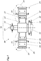
- FIG. 1 shows the schematic structure of a vertical-axis motor generator with air cooling, as it is suitable for carrying out the invention.
- the motor generator 10 comprises a rotor 34 which is arranged rotatably about a machine axis 15 and which has a rotor shaft or hub 11 on which a rotor winding 16 is provided in the form of pole windings arranged in a distributed manner.
- the rotor winding 16 is connected to the rotor shaft 11 via a rotor star 21.
- the rotor shaft 11 is rotatably supported with the aid of radial bearings 12, 13 and axial bearings 14.
- the rotor star 21 is designed to guide cooling air 24, which enters through inlet openings 22 and exits through the rotor winding 16 in the radial direction by means of corresponding passage channels 23 in the rotor winding 16.
- the rotor winding 16 is concentrically surrounded by a stator 35, the one Has stator winding 17 mounted in a stator lamination stack 18.
- the cooling air emerging from the rotor winding 16 flows through the stator 35 in the radial direction and, after exiting the stator 35, is cooled by externally arranged coolers 19 through which water 20 flows.
- the cooling air 24 cooled down in the coolers 19 is returned to the rotor 34 and re-enters the rotor star 21 with the cooling circuit being closed.
- the design and function of the throttle devices can vary depending on the requirements: A throttle device is in Figs. 2 and 3 reproduced.
- the throttle device 28 of Fig. 2 comprises according to the invention a multiplicity of individual throttle elements 29, which are arranged evenly distributed in an otherwise impermeable wall.
- the individual throttle element 29 has ( Fig. 3 ) a (in the example circular) passage opening 30 in which a throttle valve 33 is arranged to be pivotable about an axis of rotation 31 by means of a flap axis 32 in the manner of a flap valve.
- the passage opening 30 is more or less open.
- the pressure loss coefficient and thus the pressure drop can be influenced via the position of the throttle valve 33.
- the individual "throttles" or throttle elements 29 can be combined as required.
- the task of the throttle devices is always to influence the pressure drop and thus the volume flow.
- the volume flow is set continuously while the system is in operation.
- the optimal volume flow is set via the temperature monitoring of the generator.
- a throttle control can be provided which receives temperature information from a temperature sensor and then controls the throttling in the throttle device 25.
- this can be done once during commissioning or, if necessary, the volume flow can also be regulated dynamically depending on the load case.
- the throttle devices 25 and 28 can be manufactured simply and robustly, since there are no special requirements with regard to tolerances.
Landscapes
- Engineering & Computer Science (AREA)
- Power Engineering (AREA)
- Motor Or Generator Cooling System (AREA)
Description
- Die vorliegende Erfindung bezieht sich auf das Gebiet der rotierenden elektrischen Maschinen. Sie betrifft einen luftgekühlten Motorgenerator gemäss dem Oberbegriff des Anspruchs 1.
- Luftgekühlte Motorgeneratoren werden häufig über einen geschlossenen Luftkreislauf gekühlt. Die erforderliche Luftmenge wird durch die abzuführenden Verluste bestimmt. Da sowohl die anfallenden Verluste wie auch der generierte Kühlluftvolumenstrom im Vorfeld nicht exakt bestimmt werden können, müssen Reserven bezüglich des Volumenstromes eingeplant werden. Eine zu niedrige Luftmenge führt zur Überhitzung des Generators. Ein zu hoher Volumenstrom führt zu unnötigen Verlusten seitens der Ventilation. Ziel ist es also, den Kühlluftvolumenstrom so hoch wie nötig aber so niedrig wie möglich zu wählen. In der Regel wird der Volumenstrom durch künstlich erzeugte Druckabfälle innerhalb des Luftkreislaufes begrenzt (Drosselprinzip).
-
EP 0 299 908 A1 beschreibt eine elektrische Maschine mit einem geschlossenen Kühlkreislauf für ein gasförmiges Kühlmedium, welcher aufgeteilt ist in wenigstens zwei Wärmetauscher, die durch Trennwände und Flächen getrennt sind. -
JP 2008 067471 A -
WO 03 040 641 A1 -
JP 59 157491 A - Die vorliegende Erfindung vereinfacht und optimiert diese Vorgehensweise. Ziel ist es, den Kühlluftvolumenstrom den Anforderungen an die Kühlung möglichst genau anzupassen; sei dies einmalig, bei der Inbetriebnahme von Generatoren, oder häufiger, bei unterschiedlichen Lastfällen des Generators, wie sie bei Asynchronmaschinen vorkommen. Konventionell wird dies bei Wasserkraftmaschinen, wie sie z.B. in der
Fig. 1 der DruckschriftEP 740 402 A1 - Dieses Vorgehen hat jedoch einige Nachteile:
- Das Montieren der Abdeckbleche auf dem Rotorstern ist je nach Konstruktion der Maschine bei eingebautem Rotor nicht mehr möglich. Die Öffnungsfläche beim Rotorsterneintritt muss also schon vor dem Rotoreinbau fix definiert werden.
- Falls das Einbringen der zusätzlichen Bleche bei eingebautem Rotor möglich ist, kann dies auch nur bei stehender Maschine erfolgen. Dies ist zeitaufwändig und der Volumenstrom kann trotzdem nicht exakt beeinflusst werden.
- Die Abdeckbleche bringen zusätzliches Gewicht mit sich, das die Lager belastet. Darüber hinaus müssen die Bleche entsprechend sorgfältig fixiert werden, da sie sich auf dem rotierenden Teil des Generators befinden.
- Die Volumenstromverteilung, die entscheidend für die Gleichmässigkeit der Kühlung und somit der Temperaturen in der Maschine ist, kann negativ beeinflusst werden.
- Auf unterschiedliche Lastfälle des Generators kann nicht reagiert werden.
- Es ist daher eine Aufgabe der Erfindung, einen Motorgenerator zu schaffen, welcher bezüglich der Kühlung die Nachteile der herkömmlichen Lösungen vermeidet und es ermöglicht, eine Drosselung im laufenden Betrieb vorzunehmen beziehungsweise den Volumenstrom der Kühlluft exakt den jeweiligen Anforderungen anzupassen, und dies insbesondere auch dynamisch bei unterschiedlicher Last. Dabei sollen die Lager der Maschine nicht zusätzlich belastet werden.
- Die Aufgabe wird durch die Gesamtheit der Merkmale des Anspruchs 1 gelöst. Gemäss der Erfindung umfasst der luftgekühlte Motorgenerator einen Rotor mit einer um eine Maschinenachse drehbar angeordneten Rotorwelle, auf welcher eine Rotorwicklung angeordnet ist, sowie einen Stator mit einem Statorblechpaket und einer darin angeordneten Statorwicklung, welche die Rotorwicklung konzentrisch umgeben, wobei ein mit Kühlluft arbeitender, geschlossener Kühlkreislauf vorgesehen ist, in welchem die Kühlluft die Rotorwicklung und die Statorwicklung radial von innen nach aussen durchströmt, in ausserhalb des Stators angeordneten Kühlern abgekühlt und wieder in den Rotor zurückgeführt wird. Der erfindungsgemässe Motorgenerator ist dadurch gekennzeichnet, dass zur Einstellung des Volumenstroms der Kühlluft im Kühlkreislauf an den Kühlern einstellbare Drosselvorrichtungen vorgesehen sind.
- Die vorliegende Erfindung ermöglicht eine Drosselung im laufenden Betrieb. Somit kann der Volumenstrom exakt den jeweiligen Anforderungen angepasst werden. Bei Bedarf ist dies auch dynamisch bei unterschiedlicher Last möglich. Die zusätzlich erforderlichen Bauteile befinden sich nicht im rotierenden Teil des Generators und belasten daher die Lager nicht unnötig. Bei der vorliegenden Erfindung wird praktisch am "Ende" des Kühlkreislaufes, das heisst vor oder nach den Kühlern, gedrosselt.
- Gemäss einer Ausgestaltung der Erfindung sind die Drosselvorrichtungen auf der Eintrittsseite der Kühler angeordnet.
- Gemäss einer anderen Ausgestaltung der Erfindung sind die Drosselvorrichtungen auf der Austrittsseite der Kühler angeordnet.
- Die Erfindung ist dadurch gekennzeichnet, dass die Drosselvorrichtungen eine Vielzahl von in einer Ebene senkrecht zur Strömungsrichtung verteilt angeordneten Drosselelementen aufweisen, wobei jedes der Drosselelemente eine Durchtrittsöffnung umfasst.
- In den Durchtrittsöffnungen ist erfindungsgemäss nach Art eines Klappenventils eine um eine Drehachse verschwenkbare Drosselklappe angeordnet.
- Auch hier können die Drosselelemente einzeln betätigbar sein.
- Ein Verfahren zum Betrieb eines Motorgenerators, welches nicht zur Erfindung gehört, ist dadurch gekennzeichnet, dass die Einstellung des Volumenstroms der Kühlluft bei laufendem Betrieb des Motorgenerators durch stufenlose Verstellung der Drosselvorrichtungen erfolgt.
- Gemäss einer Ausgestaltung des Verfahrens erfolgt die Einstellung des Volumenstroms mittels der Drosselvorrichtungen nach Massgabe einer am Motorgenerator gemessenen Temperatur.
- Eine andere Ausgestaltung des Verfahrens ist dadurch gekennzeichnet, dass die Einstellung des Volumenstroms einmalig bei der Inbetriebnahme des Motorgenerators erfolgt.
- Eine noch andere Ausgestaltung des Verfahrens zeichnet sich dadurch aus, dass der Volumenstrom während des Betriebs des Motorgenerators je nach Lastfall dynamisch geregelt wird.
- Die Erfindung soll nachfolgend anhand von Ausführungsbeispielen im Zusammenhang mit der Zeichnung näher erläutert werden. Es zeigen
- Fig. 1
- den schematischen Aufbau eines vertikalachsigen Motorgenerators mit Luftkühlung, wie er zur Ausführung der Erfindung geeignet ist;
- Fig. 2
- die Draufsicht in Strömungsrichtung auf eine Drosselvorrichtung; und
- Fig. 3
- den Aufbau eines einzelnen Drosselelements der Drosselvorrichtung nach
Fig. 2 . - In
Fig. 1 ist der schematische Aufbau eines vertikalachsigen Motorgenerators mit Luftkühlung wiedergegeben, wie er zur Ausführung der Erfindung geeignet ist. Der Motorgenerator 10 umfasst einen um eine Maschinenachse 15 drehbar angeordneten Rotor 34, der eine Rotorwelle oder -nabe 11 aufweist, auf der eine Rotorwicklung 16 in Form verteilt angeordneter Polwicklungen vorgesehen ist. Die Rotorwicklung 16 ist mit der Rotorwelle 11 über einen Rotorstern 21 verbunden. - Die Rotorwelle 11 ist mit Hilfe von Radiallagern 12, 13 und Axiallagern 14 drehbar gelagert. Der Rotorstern 21 ist zur Führung von Kühlluft 24 ausgebildet, die durch Eintrittsöffnungen 22 eintritt und mittels entsprechender Durchtrittskanäle 23 in der Rotorwicklung 16 in radialer Richtung durch die Rotorwicklung 16 nach aussen tritt. Die Rotorwicklung 16 ist konzentrisch von einem Stator 35 umgeben, der eine in einem Statorblechpaket 18 gelagerte Statorwicklung 17 aufweist. Die aus der Rotorwicklung 16 austretende Kühlluft durchströmt in radialer Richtung den Stator 35 und wird nach Austritt aus dem Stator 35 durch extern angeordnete Kühler 19, die von Wasser 20 durchflossen werden gekühlt. Die in den Kühlern 19 heruntergekühlte Kühlluft 24 wird zum Rotor 34 zurückgeleitet und tritt unter Schliessung des Kühlkreislaufes wieder in den Rotorstern 21 ein.
- Ausführung und Funktionsweise der Drosselvorrichtungen können je nach Anforderung variieren: Eine Drosselvorrichtung ist in
Fig. 2 und 3 wiedergegeben. Die Drosselvorrichtung 28 derFig. 2 umfasst erfindungsgemäss eine Vielzahl von einzelnen Drosselelementen 29, die in einer ansonsten undurchlässigen Wand gleichmässig verteilt angeordnet sind. Das einzelne Drosselelement 29 hat (Fig. 3 ) eine (im Beispiel kreisrunde) Durchtrittsöffnung 30, in der nach Art eines Klappenventils eine Drosselklappe 33 mittels einer Klappenachse 32 um eine Drehachse 31 verschwenkbar angeordnet ist. Je nach Schwenkstellung der Drosselklappe 33 ist die Durchtrittsöffnung 30 mehr oder weniger offen. Über die Stellung der Drosselklappe 33 kann der Druckverlustkoeffizient und somit der Druckabfall beeinflusst werden. Die einzelnen "Drosseln" bzw. Drosselelemente 29 können nach Bedarf kombiniert werden. - Die Aufgabe der Drosselvorrichtungen ist immer, den Druckabfall und somit den Volumenstrom zu beeinflussen. Die Einstellung des Volumenstromes erfolgt stufenlos im laufenden Betrieb der Anlage. Über die Temperaturüberwachung des Generators wird der optimale Volumenstrom eingestellt. Hierzu kann eine Drosselsteuerung vorgesehen werden, die Temperaturinformationen von einem Temperaturaufnehmer erhält und danach die Drosselung in der Drosselvorrichtung 25 steuert. Wie bereits erwähnt, kann dies einmalig bei der Inbetriebnahme geschehen oder bei Bedarf kann der Volumenstrom je nach Lastfall auch dynamisch geregelt werden. Im ersteren Falle kann es von Vorteil sein, im Interesse eines geringeren apparativen Aufwands zumindest einen Teil der Drosselelemente 29 als fixe Blenden auszuführen. Dies gehört jedoch nicht zur Erfindung. Indem diese hinsichtlich Querschnittsform und/oder -fläche unterschiedlich ausgebildet sind, können der Druckverlust und damit die Verteilung des Kühlluftstroms über den Querschnitt beeinflusst werden. Die Drosselvorrichtungen 25 beziehungsweise 28 können einfach und robust gefertigt werden, da keine besonderen Forderungen bezüglich der Toleranzen bestehen.
-
- 10
- Motorgenerator (luftgekühlt)
- 11
- Rotorwelle
- 12,13
- Radiallager
- 14
- Axiallager
- 15
- Maschinenachse
- 16
- Rotorwicklung
- 17
- Statorwicklung
- 18
- Statorblechpaket
- 19
- Kühler
- 20
- Wasser
- 21
- Rotorstern
- 22
- Eintrittsöffnung
- 23
- Durchtrittskanal
- 24
- Kühlluft
- 28
- Drosselvorrichtung
- 29
- Drosselelement
- 30
- Durchtrittsöffnung
- 31
- Drehachse
- 32
- Klappenachse
- 33
- Drosselklappe
- 34
- Rotor
- 35
- Stator
Claims (6)
- Luftgekühlter Motorgenerator (10), umfassend einen Rotor (34) mit einer um eine Maschinenachse (15) drehbar angeordneten Rotorwelle (11), auf welcher eine Rotorwicklung (16) angeordnet ist, sowie einen Stator (35) mit einem Statorblechpaket (18) und einer darin angeordneten Statorwicklung (17), welche die Rotorwicklung (16) konzentrisch umgeben, wobei ein mit Kühlluft (24) arbeitender, geschlossener Kühlkreislauf vorgesehen ist, in welchem die Kühlluft die Rotorwicklung (16) und die Statorwicklung (17) radial von innen nach aussen durchströmt, in ausserhalb des Stators (35) angeordneten Kühlern (19) abgekühlt und wieder in den Rotor (34) zurückgeführt wird, dadurch gekennzeichnet, dass zur Einstellung des Volumenstroms der Kühlluft im Kühlkreislauf an den Kühlern (19) einstellbare Drosselvorrichtungen (25, 28) vorgesehen sind, die eine Vielzahl von in einer Ebene senkrecht zur Strömungsrichtung verteilt angeordnete Drosselelemente (29) aufweisen, wobei jedes der Drosselelemente (29) eine Durchtrittsöffnung (30) umfasst, in welcher nach Art eines Klappenventils eine um eine Drehachse (31) verschwenkbare Drosselklappe (33) angeordnet ist und die einzelnen Drosselelemente (29) in einer ansonsten undurchlässigen Wand gleichmässig verteilt angeordnet sind.
- Motorgenerator nach Anspruch 1, dadurch gekennzeichnet, dass die Drosselvorrichtungen (25, 28) auf der Eintrittsseite der Kühler (19) angeordnet sind.
- Motorgenerator nach Anspruch 1, dadurch gekennzeichnet, dass die Drosselvorrichtungen (25, 28) auf der Austrittsseite der Kühler (19) angeordnet sind.
- Motorgenerator nach Anspruch 1, dadurch gekennzeichnet, dass die Durchtrittsöffnungen (30) hinsichtlich Querschnittsform und/oder -fläche übereinstimmen.
- Motorgenerator nach Anspruch 1, dadurch gekennzeichnet, dass die Durchtrittsöffnungen (30) hinsichtlich Querschnittsform und/oder -fläche unterschiedlich ausgebildet sind.
- Motorgenerator nach einem der Ansprüche 1, 4 oder 5, dadurch gekennzeichnet, dass die Drosselelemente (29) einzeln betätigbar sind.
Applications Claiming Priority (2)
| Application Number | Priority Date | Filing Date | Title |
|---|---|---|---|
| CH01525/10A CH703819A1 (de) | 2010-09-21 | 2010-09-21 | Luftgekühlter motorgenerator sowie verfahren zum betrieb eines solchen motorgenerators. |
| DE201010049417 DE102010049417A1 (de) | 2010-10-23 | 2010-10-23 | Luftgekühlter Motorgenerator sowie Verfahren zum Betreiben eines solchen Motorgenerators |
Publications (3)
| Publication Number | Publication Date |
|---|---|
| EP2431702A2 EP2431702A2 (de) | 2012-03-21 |
| EP2431702A3 EP2431702A3 (de) | 2015-08-19 |
| EP2431702B1 true EP2431702B1 (de) | 2020-10-28 |
Family
ID=44582559
Family Applications (1)
| Application Number | Title | Priority Date | Filing Date |
|---|---|---|---|
| EP11180190.8A Active EP2431702B1 (de) | 2010-09-21 | 2011-09-06 | Luftgekühlter Motorgenerator sowie Verfahren zum Betrieb eines solchen Motorgenerators |
Country Status (7)
| Country | Link |
|---|---|
| US (1) | US8878403B2 (de) |
| EP (1) | EP2431702B1 (de) |
| KR (1) | KR101568124B1 (de) |
| CN (1) | CN102412663B (de) |
| BR (1) | BRPI1105754A8 (de) |
| CA (1) | CA2752305C (de) |
| RU (1) | RU2543060C2 (de) |
Cited By (1)
| Publication number | Priority date | Publication date | Assignee | Title |
|---|---|---|---|---|
| US11411518B2 (en) * | 2016-07-22 | 2022-08-09 | Siemens Energy Global GmbH & Co. KG | Generator cooling |
Families Citing this family (4)
| Publication number | Priority date | Publication date | Assignee | Title |
|---|---|---|---|---|
| EP3694084A1 (de) * | 2012-06-06 | 2020-08-12 | GE Renewable Technologies | Rotor für eine elektrische maschine und verfahren zum nachrüsten |
| WO2018185799A1 (ja) * | 2017-04-03 | 2018-10-11 | 三菱電機株式会社 | 車両用交流発電機 |
| US11070101B2 (en) | 2018-01-18 | 2021-07-20 | Ge Aviation Systems Llc | Method and apparatus for cooling an rotor assembly |
| US11681309B2 (en) * | 2019-01-03 | 2023-06-20 | Westinghouse Air Brake Technologies Corporation | Thermal management system and method |
Citations (1)
| Publication number | Priority date | Publication date | Assignee | Title |
|---|---|---|---|---|
| US20090146512A1 (en) * | 2005-08-31 | 2009-06-11 | Mitsubishi Electric Corporation | Cooling device of electric motor for vehicle |
Family Cites Families (18)
| Publication number | Priority date | Publication date | Assignee | Title |
|---|---|---|---|---|
| US3508092A (en) * | 1968-06-19 | 1970-04-21 | Air Reduction | Heat sink for stator winding of dynamo-electric machine |
| JPS59157491A (ja) * | 1983-02-28 | 1984-09-06 | Mitsui Eng & Shipbuild Co Ltd | ガス−液熱交換器の回収熱量のコントロ−ル方法 |
| DE3724186A1 (de) * | 1987-07-17 | 1989-01-26 | Siemens Ag | Elektrische maschine mit geschlossenem kuehlkreislauf |
| SU1552273A1 (ru) * | 1988-06-27 | 1990-03-23 | Институт сверхтвердых материалов АН УССР | Токосъемное устройство электрической машины |
| SU1709468A2 (ru) * | 1990-02-07 | 1992-01-30 | Научно-исследовательский, проектно-конструкторский и технологический институт тяжелого электромашиностроения Харьковского завода "Электротяжмаш" им.В.И.Ленина | Электрическа машина |
| RU2042252C1 (ru) * | 1992-01-22 | 1995-08-20 | Ленинградское производственное электромашиностроительное объединение "Электросила" | Электрическая машина с водяным охлаждением обмоток ротора |
| RU2047257C1 (ru) * | 1992-02-19 | 1995-10-27 | Научно-исследовательский, проектно-конструкторский и технологический институт тяжелого электромашиностроения Харьковского завода "Электротяжмаш" им.В.И.Ленина | Статор электрической машины |
| JP2758535B2 (ja) * | 1992-07-16 | 1998-05-28 | 株式会社日立製作所 | 電子スロットル制御装置 |
| DE19515260A1 (de) | 1995-04-26 | 1996-10-31 | Abb Management Ag | Vertikalachsige elektrische Wasserkraftmaschine |
| US5869912A (en) * | 1997-07-25 | 1999-02-09 | General Electric Co. | Direct-cooled dynamoelectric machine stator core with enhanced heat transfer capability |
| DE19736785A1 (de) * | 1997-08-23 | 1999-02-25 | Abb Research Ltd | Turbogenerator |
| WO2003040641A1 (en) * | 2001-11-09 | 2003-05-15 | Aalborg Industries A/S | A heat exchanger, combination with heat exchanger and method of manufacturing the heat exchanger |
| US6639334B2 (en) * | 2001-11-30 | 2003-10-28 | Ballard Power Systems Corporation | Jet impingement cooling of electric motor end-windings |
| JP4572647B2 (ja) * | 2004-10-01 | 2010-11-04 | 株式会社日立製作所 | 永久磁石式回転電機及び風力発電システム |
| DE102006025487A1 (de) * | 2005-06-07 | 2006-12-14 | Alstom Technology Ltd. | Dynamoelektrische Maschine mit einem bürstenlosen Erreger |
| JP2008067471A (ja) * | 2006-09-06 | 2008-03-21 | Toshiba Corp | 回転電機および回転電機の冷却方法 |
| KR100942274B1 (ko) | 2009-05-25 | 2010-02-16 | (주)써니콘트롤스 | 개도량 표시기능을 갖는 자동제어반의 댐퍼조절 시스템 |
| US8392097B2 (en) * | 2010-07-08 | 2013-03-05 | GM Global Technology Operations LLC | Method for starting an internal combustion engine within a hybrid powertrain |
-
2011
- 2011-09-06 EP EP11180190.8A patent/EP2431702B1/de active Active
- 2011-09-09 US US13/228,812 patent/US8878403B2/en active Active
- 2011-09-14 CA CA2752305A patent/CA2752305C/en active Active
- 2011-09-20 CN CN201110289957.9A patent/CN102412663B/zh active Active
- 2011-09-20 RU RU2011138649/07A patent/RU2543060C2/ru active
- 2011-09-20 KR KR1020110094853A patent/KR101568124B1/ko active Active
- 2011-09-21 BR BRPI1105754A patent/BRPI1105754A8/pt not_active Application Discontinuation
Patent Citations (1)
| Publication number | Priority date | Publication date | Assignee | Title |
|---|---|---|---|---|
| US20090146512A1 (en) * | 2005-08-31 | 2009-06-11 | Mitsubishi Electric Corporation | Cooling device of electric motor for vehicle |
Cited By (1)
| Publication number | Priority date | Publication date | Assignee | Title |
|---|---|---|---|---|
| US11411518B2 (en) * | 2016-07-22 | 2022-08-09 | Siemens Energy Global GmbH & Co. KG | Generator cooling |
Also Published As
| Publication number | Publication date |
|---|---|
| EP2431702A3 (de) | 2015-08-19 |
| RU2011138649A (ru) | 2013-03-27 |
| KR20120030980A (ko) | 2012-03-29 |
| CN102412663B (zh) | 2016-04-06 |
| CN102412663A (zh) | 2012-04-11 |
| CA2752305A1 (en) | 2012-03-21 |
| BRPI1105754A2 (pt) | 2013-01-08 |
| BRPI1105754A8 (pt) | 2016-04-12 |
| EP2431702A2 (de) | 2012-03-21 |
| US8878403B2 (en) | 2014-11-04 |
| KR101568124B1 (ko) | 2015-11-11 |
| CA2752305C (en) | 2016-05-03 |
| US20120068561A1 (en) | 2012-03-22 |
| RU2543060C2 (ru) | 2015-02-27 |
Similar Documents
| Publication | Publication Date | Title |
|---|---|---|
| EP2975742B1 (de) | Elektrische Maschine mit verbesserter Kühlung | |
| EP3474418B1 (de) | Elektrische maschine | |
| DE102008022105B4 (de) | Flüssigkeitsgekühlte elektrische Maschine sowie Verfahren zur Kühlung einer solchen elektrischen Maschine | |
| DE112011103349B4 (de) | Kühlmittel-Ablasssystem und Verfahren für eine elektrische Maschine | |
| DE2165847A1 (de) | Hermetisch abgeschlossene dynamoelektrische Maschine | |
| DE112015007075T5 (de) | elektrische Rotationsmaschinenkühlstruktur und Steuerverfahren davon | |
| EP3207616B1 (de) | Elektrische rotierende maschine mit einseitiger kühlung und verfahren zur einseitigen kühlung | |
| DE102010056567A1 (de) | Flüssigkeits-Luft-Kühlsystem | |
| DE102014018223A1 (de) | Elektrische Maschine, insbesondere Asynchronmaschine | |
| DE102015011863B4 (de) | Elektrische Maschine | |
| EP2537237A1 (de) | Motoreinheit | |
| DE102021130471B4 (de) | Elektrische Maschine und Verfahren zum Betreiben derselben | |
| AT521060A1 (de) | Stator | |
| DE112016003754T5 (de) | Vertikale Lagervorrichtung | |
| EP3844009A1 (de) | Verfahren zur überwachung eines ölflusses in einem ölkühlkreis | |
| WO2015120914A1 (de) | Elektrische maschine mit rahmen und hülle | |
| EP2431702A2 (de) | Luftgekühlter Motorgenerator sowie Verfahren zum Betrieb eines solchen Motorgenerators | |
| DE202018003585U1 (de) | Vakuumpumpe | |
| EP4331095B1 (de) | Elektrische maschine | |
| EP1182764A1 (de) | Kühlung für schnelllaufende elektrische Maschinen | |
| EP3668808B1 (de) | Direktantrieb für saumwickler in der metallbearbeitung | |
| CH703819A1 (de) | Luftgekühlter motorgenerator sowie verfahren zum betrieb eines solchen motorgenerators. | |
| EP2993766A1 (de) | Verbesserte Kühlung eines Ringmotors | |
| DE102006006839B4 (de) | Elektrische Maschine (Generator oder Motor) | |
| WO2015124450A1 (de) | Kühlkreislauf mit mindestens zwei kühlmitteln für elektrische maschine |
Legal Events
| Date | Code | Title | Description |
|---|---|---|---|
| PUAI | Public reference made under article 153(3) epc to a published international application that has entered the european phase |
Free format text: ORIGINAL CODE: 0009012 |
|
| AK | Designated contracting states |
Kind code of ref document: A2 Designated state(s): AL AT BE BG CH CY CZ DE DK EE ES FI FR GB GR HR HU IE IS IT LI LT LU LV MC MK MT NL NO PL PT RO RS SE SI SK SM TR |
|
| AX | Request for extension of the european patent |
Extension state: BA ME |
|
| RAP1 | Party data changed (applicant data changed or rights of an application transferred) |
Owner name: ALSTOM RENEWABLE TECHNOLOGIES |
|
| RIC1 | Information provided on ipc code assigned before grant |
Ipc: F28F 27/02 20060101ALN20150216BHEP Ipc: F28D 21/00 20060101ALN20150216BHEP Ipc: H02K 1/32 20060101ALN20150216BHEP Ipc: H02K 1/20 20060101ALN20150216BHEP Ipc: H02K 9/12 20060101ALI20150216BHEP Ipc: H02K 9/18 20060101AFI20150216BHEP |
|
| PUAL | Search report despatched |
Free format text: ORIGINAL CODE: 0009013 |
|
| AK | Designated contracting states |
Kind code of ref document: A3 Designated state(s): AL AT BE BG CH CY CZ DE DK EE ES FI FR GB GR HR HU IE IS IT LI LT LU LV MC MK MT NL NO PL PT RO RS SE SI SK SM TR |
|
| AX | Request for extension of the european patent |
Extension state: BA ME |
|
| RIC1 | Information provided on ipc code assigned before grant |
Ipc: H02K 1/32 20060101ALN20150710BHEP Ipc: F28D 21/00 20060101ALN20150710BHEP Ipc: F28F 27/02 20060101ALN20150710BHEP Ipc: H02K 1/20 20060101ALN20150710BHEP Ipc: H02K 9/12 20060101ALI20150710BHEP Ipc: H02K 9/18 20060101AFI20150710BHEP |
|
| 17P | Request for examination filed |
Effective date: 20160209 |
|
| RBV | Designated contracting states (corrected) |
Designated state(s): AL AT BE BG CH CY CZ DE DK EE ES FI FR GB GR HR HU IE IS IT LI LT LU LV MC MK MT NL NO PL PT RO RS SE SI SK SM TR |
|
| 17Q | First examination report despatched |
Effective date: 20161020 |
|
| STAA | Information on the status of an ep patent application or granted ep patent |
Free format text: STATUS: EXAMINATION IS IN PROGRESS |
|
| RAP1 | Party data changed (applicant data changed or rights of an application transferred) |
Owner name: GE RENEWABLE TECHNOLOGIES |
|
| REG | Reference to a national code |
Ref country code: DE Ref legal event code: R079 Ref document number: 502011016955 Country of ref document: DE Free format text: PREVIOUS MAIN CLASS: F28F0027000000 Ipc: H02K0009180000 |
|
| RIC1 | Information provided on ipc code assigned before grant |
Ipc: H02K 1/20 20060101ALN20200327BHEP Ipc: H02K 1/32 20060101ALN20200327BHEP Ipc: H02K 9/12 20060101ALI20200327BHEP Ipc: F28F 27/02 20060101ALN20200327BHEP Ipc: F28D 21/00 20060101ALN20200327BHEP Ipc: H02K 9/18 20060101AFI20200327BHEP |
|
| GRAP | Despatch of communication of intention to grant a patent |
Free format text: ORIGINAL CODE: EPIDOSNIGR1 |
|
| STAA | Information on the status of an ep patent application or granted ep patent |
Free format text: STATUS: GRANT OF PATENT IS INTENDED |
|
| INTG | Intention to grant announced |
Effective date: 20200514 |
|
| GRAS | Grant fee paid |
Free format text: ORIGINAL CODE: EPIDOSNIGR3 |
|
| GRAA | (expected) grant |
Free format text: ORIGINAL CODE: 0009210 |
|
| STAA | Information on the status of an ep patent application or granted ep patent |
Free format text: STATUS: THE PATENT HAS BEEN GRANTED |
|
| AK | Designated contracting states |
Kind code of ref document: B1 Designated state(s): AL AT BE BG CH CY CZ DE DK EE ES FI FR GB GR HR HU IE IS IT LI LT LU LV MC MK MT NL NO PL PT RO RS SE SI SK SM TR |
|
| AX | Request for extension of the european patent |
Extension state: BA |
|
| REG | Reference to a national code |
Ref country code: GB Ref legal event code: FG4D Free format text: NOT ENGLISH |
|
| REG | Reference to a national code |
Ref country code: CH Ref legal event code: EP |
|
| REG | Reference to a national code |
Ref country code: AT Ref legal event code: REF Ref document number: 1329226 Country of ref document: AT Kind code of ref document: T Effective date: 20201115 |
|
| REG | Reference to a national code |
Ref country code: DE Ref legal event code: R096 Ref document number: 502011016955 Country of ref document: DE |
|
| REG | Reference to a national code |
Ref country code: IE Ref legal event code: FG4D Free format text: LANGUAGE OF EP DOCUMENT: GERMAN |
|
| REG | Reference to a national code |
Ref country code: CH Ref legal event code: NV Representative=s name: VALIPAT S.A. C/O BOVARD SA NEUCHATEL, CH |
|
| REG | Reference to a national code |
Ref country code: NL Ref legal event code: MP Effective date: 20201028 |
|
| PG25 | Lapsed in a contracting state [announced via postgrant information from national office to epo] |
Ref country code: PT Free format text: LAPSE BECAUSE OF FAILURE TO SUBMIT A TRANSLATION OF THE DESCRIPTION OR TO PAY THE FEE WITHIN THE PRESCRIBED TIME-LIMIT Effective date: 20210301 Ref country code: NO Free format text: LAPSE BECAUSE OF FAILURE TO SUBMIT A TRANSLATION OF THE DESCRIPTION OR TO PAY THE FEE WITHIN THE PRESCRIBED TIME-LIMIT Effective date: 20210128 Ref country code: NL Free format text: LAPSE BECAUSE OF FAILURE TO SUBMIT A TRANSLATION OF THE DESCRIPTION OR TO PAY THE FEE WITHIN THE PRESCRIBED TIME-LIMIT Effective date: 20201028 Ref country code: FI Free format text: LAPSE BECAUSE OF FAILURE TO SUBMIT A TRANSLATION OF THE DESCRIPTION OR TO PAY THE FEE WITHIN THE PRESCRIBED TIME-LIMIT Effective date: 20201028 Ref country code: RS Free format text: LAPSE BECAUSE OF FAILURE TO SUBMIT A TRANSLATION OF THE DESCRIPTION OR TO PAY THE FEE WITHIN THE PRESCRIBED TIME-LIMIT Effective date: 20201028 Ref country code: GR Free format text: LAPSE BECAUSE OF FAILURE TO SUBMIT A TRANSLATION OF THE DESCRIPTION OR TO PAY THE FEE WITHIN THE PRESCRIBED TIME-LIMIT Effective date: 20210129 |
|
| REG | Reference to a national code |
Ref country code: LT Ref legal event code: MG4D |
|
| PG25 | Lapsed in a contracting state [announced via postgrant information from national office to epo] |
Ref country code: BG Free format text: LAPSE BECAUSE OF FAILURE TO SUBMIT A TRANSLATION OF THE DESCRIPTION OR TO PAY THE FEE WITHIN THE PRESCRIBED TIME-LIMIT Effective date: 20210128 Ref country code: IS Free format text: LAPSE BECAUSE OF FAILURE TO SUBMIT A TRANSLATION OF THE DESCRIPTION OR TO PAY THE FEE WITHIN THE PRESCRIBED TIME-LIMIT Effective date: 20210228 Ref country code: ES Free format text: LAPSE BECAUSE OF FAILURE TO SUBMIT A TRANSLATION OF THE DESCRIPTION OR TO PAY THE FEE WITHIN THE PRESCRIBED TIME-LIMIT Effective date: 20201028 Ref country code: PL Free format text: LAPSE BECAUSE OF FAILURE TO SUBMIT A TRANSLATION OF THE DESCRIPTION OR TO PAY THE FEE WITHIN THE PRESCRIBED TIME-LIMIT Effective date: 20201028 Ref country code: SE Free format text: LAPSE BECAUSE OF FAILURE TO SUBMIT A TRANSLATION OF THE DESCRIPTION OR TO PAY THE FEE WITHIN THE PRESCRIBED TIME-LIMIT Effective date: 20201028 Ref country code: LV Free format text: LAPSE BECAUSE OF FAILURE TO SUBMIT A TRANSLATION OF THE DESCRIPTION OR TO PAY THE FEE WITHIN THE PRESCRIBED TIME-LIMIT Effective date: 20201028 |
|
| PG25 | Lapsed in a contracting state [announced via postgrant information from national office to epo] |
Ref country code: HR Free format text: LAPSE BECAUSE OF FAILURE TO SUBMIT A TRANSLATION OF THE DESCRIPTION OR TO PAY THE FEE WITHIN THE PRESCRIBED TIME-LIMIT Effective date: 20201028 |
|
| REG | Reference to a national code |
Ref country code: DE Ref legal event code: R097 Ref document number: 502011016955 Country of ref document: DE |
|
| PG25 | Lapsed in a contracting state [announced via postgrant information from national office to epo] |
Ref country code: LT Free format text: LAPSE BECAUSE OF FAILURE TO SUBMIT A TRANSLATION OF THE DESCRIPTION OR TO PAY THE FEE WITHIN THE PRESCRIBED TIME-LIMIT Effective date: 20201028 Ref country code: RO Free format text: LAPSE BECAUSE OF FAILURE TO SUBMIT A TRANSLATION OF THE DESCRIPTION OR TO PAY THE FEE WITHIN THE PRESCRIBED TIME-LIMIT Effective date: 20201028 Ref country code: SK Free format text: LAPSE BECAUSE OF FAILURE TO SUBMIT A TRANSLATION OF THE DESCRIPTION OR TO PAY THE FEE WITHIN THE PRESCRIBED TIME-LIMIT Effective date: 20201028 Ref country code: CZ Free format text: LAPSE BECAUSE OF FAILURE TO SUBMIT A TRANSLATION OF THE DESCRIPTION OR TO PAY THE FEE WITHIN THE PRESCRIBED TIME-LIMIT Effective date: 20201028 Ref country code: EE Free format text: LAPSE BECAUSE OF FAILURE TO SUBMIT A TRANSLATION OF THE DESCRIPTION OR TO PAY THE FEE WITHIN THE PRESCRIBED TIME-LIMIT Effective date: 20201028 Ref country code: SM Free format text: LAPSE BECAUSE OF FAILURE TO SUBMIT A TRANSLATION OF THE DESCRIPTION OR TO PAY THE FEE WITHIN THE PRESCRIBED TIME-LIMIT Effective date: 20201028 |
|
| PG25 | Lapsed in a contracting state [announced via postgrant information from national office to epo] |
Ref country code: DK Free format text: LAPSE BECAUSE OF FAILURE TO SUBMIT A TRANSLATION OF THE DESCRIPTION OR TO PAY THE FEE WITHIN THE PRESCRIBED TIME-LIMIT Effective date: 20201028 |
|
| PLBE | No opposition filed within time limit |
Free format text: ORIGINAL CODE: 0009261 |
|
| STAA | Information on the status of an ep patent application or granted ep patent |
Free format text: STATUS: NO OPPOSITION FILED WITHIN TIME LIMIT |
|
| 26N | No opposition filed |
Effective date: 20210729 |
|
| PG25 | Lapsed in a contracting state [announced via postgrant information from national office to epo] |
Ref country code: AL Free format text: LAPSE BECAUSE OF FAILURE TO SUBMIT A TRANSLATION OF THE DESCRIPTION OR TO PAY THE FEE WITHIN THE PRESCRIBED TIME-LIMIT Effective date: 20201028 Ref country code: IT Free format text: LAPSE BECAUSE OF FAILURE TO SUBMIT A TRANSLATION OF THE DESCRIPTION OR TO PAY THE FEE WITHIN THE PRESCRIBED TIME-LIMIT Effective date: 20201028 |
|
| PG25 | Lapsed in a contracting state [announced via postgrant information from national office to epo] |
Ref country code: SI Free format text: LAPSE BECAUSE OF FAILURE TO SUBMIT A TRANSLATION OF THE DESCRIPTION OR TO PAY THE FEE WITHIN THE PRESCRIBED TIME-LIMIT Effective date: 20201028 |
|
| REG | Reference to a national code |
Ref country code: BE Ref legal event code: MM Effective date: 20210930 |
|
| GBPC | Gb: european patent ceased through non-payment of renewal fee |
Effective date: 20210906 |
|
| PG25 | Lapsed in a contracting state [announced via postgrant information from national office to epo] |
Ref country code: IS Free format text: LAPSE BECAUSE OF FAILURE TO SUBMIT A TRANSLATION OF THE DESCRIPTION OR TO PAY THE FEE WITHIN THE PRESCRIBED TIME-LIMIT Effective date: 20210228 Ref country code: MC Free format text: LAPSE BECAUSE OF FAILURE TO SUBMIT A TRANSLATION OF THE DESCRIPTION OR TO PAY THE FEE WITHIN THE PRESCRIBED TIME-LIMIT Effective date: 20201028 |
|
| PG25 | Lapsed in a contracting state [announced via postgrant information from national office to epo] |
Ref country code: LU Free format text: LAPSE BECAUSE OF NON-PAYMENT OF DUE FEES Effective date: 20210906 Ref country code: IE Free format text: LAPSE BECAUSE OF NON-PAYMENT OF DUE FEES Effective date: 20210906 Ref country code: GB Free format text: LAPSE BECAUSE OF NON-PAYMENT OF DUE FEES Effective date: 20210906 Ref country code: FR Free format text: LAPSE BECAUSE OF NON-PAYMENT OF DUE FEES Effective date: 20210930 Ref country code: BE Free format text: LAPSE BECAUSE OF NON-PAYMENT OF DUE FEES Effective date: 20210930 |
|
| PG25 | Lapsed in a contracting state [announced via postgrant information from national office to epo] |
Ref country code: HU Free format text: LAPSE BECAUSE OF FAILURE TO SUBMIT A TRANSLATION OF THE DESCRIPTION OR TO PAY THE FEE WITHIN THE PRESCRIBED TIME-LIMIT; INVALID AB INITIO Effective date: 20110906 Ref country code: CY Free format text: LAPSE BECAUSE OF FAILURE TO SUBMIT A TRANSLATION OF THE DESCRIPTION OR TO PAY THE FEE WITHIN THE PRESCRIBED TIME-LIMIT Effective date: 20201028 |
|
| P01 | Opt-out of the competence of the unified patent court (upc) registered |
Effective date: 20230522 |
|
| PG25 | Lapsed in a contracting state [announced via postgrant information from national office to epo] |
Ref country code: MK Free format text: LAPSE BECAUSE OF FAILURE TO SUBMIT A TRANSLATION OF THE DESCRIPTION OR TO PAY THE FEE WITHIN THE PRESCRIBED TIME-LIMIT Effective date: 20201028 |
|
| PG25 | Lapsed in a contracting state [announced via postgrant information from national office to epo] |
Ref country code: TR Free format text: LAPSE BECAUSE OF FAILURE TO SUBMIT A TRANSLATION OF THE DESCRIPTION OR TO PAY THE FEE WITHIN THE PRESCRIBED TIME-LIMIT Effective date: 20201028 |
|
| PG25 | Lapsed in a contracting state [announced via postgrant information from national office to epo] |
Ref country code: MT Free format text: LAPSE BECAUSE OF FAILURE TO SUBMIT A TRANSLATION OF THE DESCRIPTION OR TO PAY THE FEE WITHIN THE PRESCRIBED TIME-LIMIT Effective date: 20201028 |
|
| REG | Reference to a national code |
Ref country code: CH Ref legal event code: U11 Free format text: ST27 STATUS EVENT CODE: U-0-0-U10-U11 (AS PROVIDED BY THE NATIONAL OFFICE) Effective date: 20251001 |
|
| PGFP | Annual fee paid to national office [announced via postgrant information from national office to epo] |
Ref country code: DE Payment date: 20250820 Year of fee payment: 15 |
|
| PGFP | Annual fee paid to national office [announced via postgrant information from national office to epo] |
Ref country code: AT Payment date: 20250822 Year of fee payment: 15 |
|
| PGFP | Annual fee paid to national office [announced via postgrant information from national office to epo] |
Ref country code: CH Payment date: 20251001 Year of fee payment: 15 |