EP2431617B1 - Montagesystem zur Festlegung von plattenförmigen Flächenelementen - Google Patents
Montagesystem zur Festlegung von plattenförmigen Flächenelementen Download PDFInfo
- Publication number
- EP2431617B1 EP2431617B1 EP11181067.7A EP11181067A EP2431617B1 EP 2431617 B1 EP2431617 B1 EP 2431617B1 EP 11181067 A EP11181067 A EP 11181067A EP 2431617 B1 EP2431617 B1 EP 2431617B1
- Authority
- EP
- European Patent Office
- Prior art keywords
- mounting system
- shaped portion
- securing pin
- area element
- securing
- Prior art date
- Legal status (The legal status is an assumption and is not a legal conclusion. Google has not performed a legal analysis and makes no representation as to the accuracy of the status listed.)
- Active
Links
- 229920003023 plastic Polymers 0.000 claims description 3
- 239000004033 plastic Substances 0.000 claims description 3
- 239000000463 material Substances 0.000 claims 1
- 230000000717 retained effect Effects 0.000 claims 1
- 230000037431 insertion Effects 0.000 description 8
- 238000003780 insertion Methods 0.000 description 8
- 239000011521 glass Substances 0.000 description 3
- 239000002184 metal Substances 0.000 description 3
- 238000009434 installation Methods 0.000 description 2
- 210000000078 claw Anatomy 0.000 description 1
- 238000010276 construction Methods 0.000 description 1
- 230000006378 damage Effects 0.000 description 1
- 230000001066 destructive effect Effects 0.000 description 1
- 230000010339 dilation Effects 0.000 description 1
- 239000013013 elastic material Substances 0.000 description 1
- 125000006850 spacer group Chemical group 0.000 description 1
- 230000007704 transition Effects 0.000 description 1
Images


Classifications
-
- F—MECHANICAL ENGINEERING; LIGHTING; HEATING; WEAPONS; BLASTING
- F16—ENGINEERING ELEMENTS AND UNITS; GENERAL MEASURES FOR PRODUCING AND MAINTAINING EFFECTIVE FUNCTIONING OF MACHINES OR INSTALLATIONS; THERMAL INSULATION IN GENERAL
- F16B—DEVICES FOR FASTENING OR SECURING CONSTRUCTIONAL ELEMENTS OR MACHINE PARTS TOGETHER, e.g. NAILS, BOLTS, CIRCLIPS, CLAMPS, CLIPS OR WEDGES; JOINTS OR JOINTING
- F16B5/00—Joining sheets or plates, e.g. panels, to one another or to strips or bars parallel to them
- F16B5/0004—Joining sheets, plates or panels in abutting relationship
- F16B5/0084—Joining sheets, plates or panels in abutting relationship characterised by particular locking means
-
- F—MECHANICAL ENGINEERING; LIGHTING; HEATING; WEAPONS; BLASTING
- F24—HEATING; RANGES; VENTILATING
- F24S—SOLAR HEAT COLLECTORS; SOLAR HEAT SYSTEMS
- F24S25/00—Arrangement of stationary mountings or supports for solar heat collector modules
- F24S25/30—Arrangement of stationary mountings or supports for solar heat collector modules using elongate rigid mounting elements extending substantially along the supporting surface, e.g. for covering buildings with solar heat collectors
- F24S25/33—Arrangement of stationary mountings or supports for solar heat collector modules using elongate rigid mounting elements extending substantially along the supporting surface, e.g. for covering buildings with solar heat collectors forming substantially planar assemblies, e.g. of coplanar or stacked profiles
- F24S25/35—Arrangement of stationary mountings or supports for solar heat collector modules using elongate rigid mounting elements extending substantially along the supporting surface, e.g. for covering buildings with solar heat collectors forming substantially planar assemblies, e.g. of coplanar or stacked profiles by means of profiles with a cross-section defining separate supporting portions for adjacent modules
-
- F—MECHANICAL ENGINEERING; LIGHTING; HEATING; WEAPONS; BLASTING
- F24—HEATING; RANGES; VENTILATING
- F24S—SOLAR HEAT COLLECTORS; SOLAR HEAT SYSTEMS
- F24S25/00—Arrangement of stationary mountings or supports for solar heat collector modules
- F24S25/30—Arrangement of stationary mountings or supports for solar heat collector modules using elongate rigid mounting elements extending substantially along the supporting surface, e.g. for covering buildings with solar heat collectors
- F24S25/33—Arrangement of stationary mountings or supports for solar heat collector modules using elongate rigid mounting elements extending substantially along the supporting surface, e.g. for covering buildings with solar heat collectors forming substantially planar assemblies, e.g. of coplanar or stacked profiles
- F24S25/37—Arrangement of stationary mountings or supports for solar heat collector modules using elongate rigid mounting elements extending substantially along the supporting surface, e.g. for covering buildings with solar heat collectors forming substantially planar assemblies, e.g. of coplanar or stacked profiles forming coplanar grids comprising longitudinal and transversal profiles
-
- H—ELECTRICITY
- H02—GENERATION; CONVERSION OR DISTRIBUTION OF ELECTRIC POWER
- H02S—GENERATION OF ELECTRIC POWER BY CONVERSION OF INFRARED RADIATION, VISIBLE LIGHT OR ULTRAVIOLET LIGHT, e.g. USING PHOTOVOLTAIC [PV] MODULES
- H02S20/00—Supporting structures for PV modules
- H02S20/20—Supporting structures directly fixed to an immovable object
- H02S20/22—Supporting structures directly fixed to an immovable object specially adapted for buildings
- H02S20/23—Supporting structures directly fixed to an immovable object specially adapted for buildings specially adapted for roof structures
-
- H—ELECTRICITY
- H02—GENERATION; CONVERSION OR DISTRIBUTION OF ELECTRIC POWER
- H02S—GENERATION OF ELECTRIC POWER BY CONVERSION OF INFRARED RADIATION, VISIBLE LIGHT OR ULTRAVIOLET LIGHT, e.g. USING PHOTOVOLTAIC [PV] MODULES
- H02S20/00—Supporting structures for PV modules
- H02S20/20—Supporting structures directly fixed to an immovable object
- H02S20/22—Supporting structures directly fixed to an immovable object specially adapted for buildings
- H02S20/26—Building materials integrated with PV modules, e.g. façade elements
-
- F—MECHANICAL ENGINEERING; LIGHTING; HEATING; WEAPONS; BLASTING
- F16—ENGINEERING ELEMENTS AND UNITS; GENERAL MEASURES FOR PRODUCING AND MAINTAINING EFFECTIVE FUNCTIONING OF MACHINES OR INSTALLATIONS; THERMAL INSULATION IN GENERAL
- F16B—DEVICES FOR FASTENING OR SECURING CONSTRUCTIONAL ELEMENTS OR MACHINE PARTS TOGETHER, e.g. NAILS, BOLTS, CIRCLIPS, CLAMPS, CLIPS OR WEDGES; JOINTS OR JOINTING
- F16B5/00—Joining sheets or plates, e.g. panels, to one another or to strips or bars parallel to them
- F16B5/0004—Joining sheets, plates or panels in abutting relationship
- F16B5/0008—Joining sheets, plates or panels in abutting relationship by moving the sheets, plates or panels substantially in their own plane, perpendicular to the abutting edge
- F16B5/0028—Joining sheets, plates or panels in abutting relationship by moving the sheets, plates or panels substantially in their own plane, perpendicular to the abutting edge using I-shaped connectors
-
- F—MECHANICAL ENGINEERING; LIGHTING; HEATING; WEAPONS; BLASTING
- F24—HEATING; RANGES; VENTILATING
- F24S—SOLAR HEAT COLLECTORS; SOLAR HEAT SYSTEMS
- F24S25/00—Arrangement of stationary mountings or supports for solar heat collector modules
- F24S2025/01—Special support components; Methods of use
- F24S2025/014—Methods for installing support elements
-
- F—MECHANICAL ENGINEERING; LIGHTING; HEATING; WEAPONS; BLASTING
- F24—HEATING; RANGES; VENTILATING
- F24S—SOLAR HEAT COLLECTORS; SOLAR HEAT SYSTEMS
- F24S25/00—Arrangement of stationary mountings or supports for solar heat collector modules
- F24S2025/01—Special support components; Methods of use
- F24S2025/018—Means for preventing movements, e.g. stops
-
- F—MECHANICAL ENGINEERING; LIGHTING; HEATING; WEAPONS; BLASTING
- F24—HEATING; RANGES; VENTILATING
- F24S—SOLAR HEAT COLLECTORS; SOLAR HEAT SYSTEMS
- F24S25/00—Arrangement of stationary mountings or supports for solar heat collector modules
- F24S2025/01—Special support components; Methods of use
- F24S2025/023—Means for preventing theft; Locking means
-
- Y—GENERAL TAGGING OF NEW TECHNOLOGICAL DEVELOPMENTS; GENERAL TAGGING OF CROSS-SECTIONAL TECHNOLOGIES SPANNING OVER SEVERAL SECTIONS OF THE IPC; TECHNICAL SUBJECTS COVERED BY FORMER USPC CROSS-REFERENCE ART COLLECTIONS [XRACs] AND DIGESTS
- Y02—TECHNOLOGIES OR APPLICATIONS FOR MITIGATION OR ADAPTATION AGAINST CLIMATE CHANGE
- Y02B—CLIMATE CHANGE MITIGATION TECHNOLOGIES RELATED TO BUILDINGS, e.g. HOUSING, HOUSE APPLIANCES OR RELATED END-USER APPLICATIONS
- Y02B10/00—Integration of renewable energy sources in buildings
- Y02B10/10—Photovoltaic [PV]
-
- Y—GENERAL TAGGING OF NEW TECHNOLOGICAL DEVELOPMENTS; GENERAL TAGGING OF CROSS-SECTIONAL TECHNOLOGIES SPANNING OVER SEVERAL SECTIONS OF THE IPC; TECHNICAL SUBJECTS COVERED BY FORMER USPC CROSS-REFERENCE ART COLLECTIONS [XRACs] AND DIGESTS
- Y02—TECHNOLOGIES OR APPLICATIONS FOR MITIGATION OR ADAPTATION AGAINST CLIMATE CHANGE
- Y02E—REDUCTION OF GREENHOUSE GAS [GHG] EMISSIONS, RELATED TO ENERGY GENERATION, TRANSMISSION OR DISTRIBUTION
- Y02E10/00—Energy generation through renewable energy sources
- Y02E10/40—Solar thermal energy, e.g. solar towers
- Y02E10/47—Mountings or tracking
-
- Y—GENERAL TAGGING OF NEW TECHNOLOGICAL DEVELOPMENTS; GENERAL TAGGING OF CROSS-SECTIONAL TECHNOLOGIES SPANNING OVER SEVERAL SECTIONS OF THE IPC; TECHNICAL SUBJECTS COVERED BY FORMER USPC CROSS-REFERENCE ART COLLECTIONS [XRACs] AND DIGESTS
- Y02—TECHNOLOGIES OR APPLICATIONS FOR MITIGATION OR ADAPTATION AGAINST CLIMATE CHANGE
- Y02E—REDUCTION OF GREENHOUSE GAS [GHG] EMISSIONS, RELATED TO ENERGY GENERATION, TRANSMISSION OR DISTRIBUTION
- Y02E10/00—Energy generation through renewable energy sources
- Y02E10/50—Photovoltaic [PV] energy
Definitions
- the present invention relates to a mounting system according to the preamble of claim 1.
- the DE 93 09 284 discloses a device for releasably holding plate-shaped elements on edge portions which are inserted into U-shaped profiles. Recesses are provided on the U-shaped profiles, are inserted through the holding members between the webs of the U-profile and the edge of the plate-shaped element, so that the plate-shaped elements are secured.
- surface elements such as glass panes or photovoltaic modules
- the support seal can be pre-assembled, while the second seal is usually pressed after inserting the surface element as a Steckkederdichtung.
- the surface elements thus mounted are usually fixed by fastening means in a predetermined position so that they do not move within the profiles, for example by dilation or other external forces.
- a disadvantage of this mounting system for surface elements is that the fastening means are accessible from the outside and after the removal of a claw of the surface elements is possible. Especially with mounting systems with photovoltaic modules, these are insufficiently secured.
- a plate-shaped surface element is held at least on one side to a U-shaped portion on which a securing bolt is provided which limits movement of the surface element to the bottom of the U-shaped portion to prevent disassembly, wherein the securing bolt has a predetermined breaking point and can only be removed by destroying the predetermined breaking point.
- the securing bolt has a predetermined breaking point and can only be removed by destroying the predetermined breaking point.
- the latter is inserted into an opening in a wall of the profile on the first side.
- the securing bolt is fixed to the bottom of the U-shaped portion, so that it is arranged protected and is also not visible from the outside. This makes it difficult to destroy the securing bolt located inside the profile.
- the predetermined breaking point can be arranged in the region of the wall of the profile, that is, for example, in the bottom of the U-shaped section, so that at least the broken part falls into the U-shaped section in the event of destruction of the securing bolt, so that the area to the bottom of the U-shaped section. shaped portion is released for moving the surface element.
- the securing bolt on a head portion which protrudes on the opposite side of the U-shaped portion.
- the head section may in particular be arranged in a second U-shaped section and form a stop for an adjacent surface element.
- the profile then has two adjacent U-shaped sections and has an H-shaped contour in this area. This makes it possible to arrange a head portion of the securing bolt in the second U-shaped portion so that it then forms a stop for an adjacent surface element. That way you can a plurality of surface elements are mounted one behind the other, wherein between two surface elements at least one securing bolt is arranged.
- the surface elements are preferably held with play between a head of a securing bolt and a Einsteckabêt a arranged on the opposite side locking bolt. As a result, a certain tolerance compensation can be made even with thermal expansions or with a relative movement of the surface element to the profile. In addition, a contact of the surface element is avoided with metal when the securing bolt is coated at least on the surface of the head portion and the insertion portion or made of plastic.
- the surface element may have a rectangular contour and be positioned on opposite sides by a plurality of securing bolts.
- the surface element is peripherally bordered between two seals between the profiles, which are supported on the legs of the U-shaped sections.
- a seal can be plugged in as Kederdichtung.
- the profiles with the U-shaped sections may further comprise an integrally formed cantilever which is fixed to a supporting structure.
- the mounting system is particularly suitable for photovoltaic modules, but also insulating glass panes on facades or skylights can be mounted in this way.
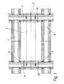
- a mounting system 1 for fixing plate-shaped surface elements 2, in particular photovoltaic modules or insulating glass panes, comprises a first and a second cover profile 3 and 4 which are fixed by screws 5.
- the cover profiles 3 and 4 on the longitudinal sides of the surface element 2 can be disassembled in a simple manner.
- the determination of the surface element 2 takes place on opposite end faces, by a profile 6 and a profile 7, which are of identical construction and surround the surface element 2 at the edge by a U-shaped section.
- securing bolts 20 are fixed to the profiles 6 and 7.
- FIG. 2 the cross section of the profiles 6 and 7 is shown in detail.
- the profiles 6 and 7 each have a U-shaped section 8 on a first side and a U-shaped section 9 on an opposite second side, so that an H is formed.
- the surface element 2 is inserted into the U-shaped section 9 in the profile 6 and in the U-shaped section 8 in the profile 7.
- An adjacent surface element 2 ' is inserted in the profile 7 in the U-shaped section 9.
- the U-shaped section 8 is formed by a first leg 11 and a second leg 12, wherein on the leg 12, a groove 13 is provided for inserting a system seal. On the leg 11 a profiling is also formed, which serves for mounting a Steckkederdichtung. As a result, the surface element 2 can be clamped at the edge of the U-shaped section 8 between two seals.
- a first leg 14 and a second leg 15 is also formed, wherein on the lower leg 15, a groove 13 is provided for a seal and the leg 14 and has a profiling for a Steckkederdichtung.
- the two U-shaped sections 8 and 9 are separated by a bottom 10, which has an opening for insertion of a securing bolt 20.
- the boom 16 is aligned and fixed by a screw 18 on a web 17 of the support structure 19 in the desired position.
- the cover profiles 3 and 4 are fixed to a boom 30 on the legs 12 and 15.
- a surface element 2 is first inserted into a U-shaped section 8 ( FIG. 3A ), Until an end face of the surface element 2 is disposed near the bottom 10. In this position, the surface element 2 can be pivoted and can be moved adjacent to the leg 14 on the U-shaped portion 9. Then, the surface element 2 can be pushed back away from the bottom 10 at the U-shaped section 8, so that in the surface element 2, the opposite edge sides are respectively inserted into a U-shaped section 8 and 9 respectively. The surface element 2 is now applied to the plant seals in the grooves 13 and can be set via Steckkederdichtitch, which are mounted on the legs 11 and 14.
- a securing bolt 20 is inserted into an opening in the bottom 10.
- the bolt 20 has a front insertion portion 21 which is arranged adjacent to an end face of the surface element 2, so that the surface element 2 is arranged with slight play.
- a head portion 29 lies in the U-shaped portion 9.
- the surface elements 2 are in each case positioned on opposite sides via at least 2 securing bolts 20 with play.
- the seal on the leg 11 is removed and inserted a hook-shaped special tool in the U-shaped portion, which is then moved in the longitudinal direction of the profile 7 to cancel the insertion portion 21.
- the user does not see where the securing bolts 20 are arranged and therefore has to move the special tool along the profile 7. If the securing bolts 20 are broken off at the insertion portions 21, they fall down to the leg 12, so that the surface element 2 can be moved to the bottom 10 and then pulled out of the U-shaped portion 9 on the opposite side.
- another spacer must be mounted, which prevents movement of the surface element relative to the profile 7.
- the securing bolt 20 is shown in detail.
- the securing bolt 20 is substantially cylindrical and includes a front male portion 21 having a smaller diameter than an opening in the bottom 10 to facilitate insertion.
- the insertion portion 21 expands at a transition 22, at which connect a plurality of spring bars 23, which are formed by slots freestanding.
- an outwardly widened portion is formed with a run-on slope 24.
- the securing bolt 20 also has a predetermined breaking point 26, which is formed as a bridge to a head portion 29 and has only a small diameter which is more than three times smaller than the diameter of the head portion 29.
- a cylindrical holding portion 27 is formed to which the predetermined breaking point 26 is formed, wherein the holding portion 27 can be inserted into the opening of the wall 10.
- a radially outwardly directed step 28 connects, which forms a stop and bears against the bottom 10, so that upon pressing a surface element 2 'against the securing bolt 20, this acts as a stop.
- the securing bolt 20 is manufactured in one piece from plastic, so that an elasticity of the spring webs 23 is provided and, moreover, a contact of metal against the surface element 2 or 2 'is avoided. It is also possible to produce the securing bolt 20 from metal and to coat the surfaces coming into contact with the surface element 2 or 2 'with an elastic material.
Landscapes
- Engineering & Computer Science (AREA)
- General Engineering & Computer Science (AREA)
- Structural Engineering (AREA)
- Civil Engineering (AREA)
- Architecture (AREA)
- Mechanical Engineering (AREA)
- Sustainable Energy (AREA)
- Thermal Sciences (AREA)
- Chemical & Material Sciences (AREA)
- Combustion & Propulsion (AREA)
- Sustainable Development (AREA)
- Life Sciences & Earth Sciences (AREA)
- Physics & Mathematics (AREA)
- Photovoltaic Devices (AREA)
- Roof Covering Using Slabs Or Stiff Sheets (AREA)
Description
- Die vorliegende Erfindung betrifft ein Montagesystem nach dem Oberbegriff des Anspruches 1.
- Die
DE 93 09 284 offenbart eine Vorrichtung zur lösbaren Halterung plattenförmiger Elemente an Randabschnitten, die in U-förmige Profile eingefügt sind. An den U-förmigen Profilen sind Ausnehmungen vorgesehen, durch die Halteorgane zwischen den Stegen des U-Profils und dem Rand des plattenförmigen Elementes eingeschoben werden, damit die plattenförmigen Elemente gesichert werden. - Es ist bekannt, dass Flächenelemente, wie Glasscheiben oder Photovoltaikmodule, werkzeuglos befestigt werden können, wenn die jeweiligen Flächenelemente zunächst an einer Seite in eine U-förmige Aufnahme eines Profils eingeschoben werden, dann verschwenkt werden und an einer gegenüberliegenden Seite in eine U-förmige Aufnahme eines weiteren Profils eingefügt werden. Dann ist das Flächenelement an gegenüberliegenden Seiten randseitig jeweils in einer U-förmigen Aufnahme gehalten und kann dort zwischen Dichtungen festgelegt werden. Die Auflagedichtung kann dabei vormontiert werden, während die zweite Dichtung nach dem Einlegen des Flächenelementes meist als Steckkederdichtung eingedrückt wird. Die so montierten Flächenelemente werden meist durch Befestigungsmittel in einer vorbestimmten Position fixiert, damit sich diese nicht innerhalb der Profile bewegen, beispielsweise durch Dilatation oder andere äußere Krafteinflüsse. Nachteilig bei diesem Montagesystem für Flächenelemente ist, dass die Befestigungsmittel von außen zugänglich sind und nach deren Entfernung ein Klauen der Flächenelemente möglich ist. Gerade bei Montagesystemen mit Photovoltaikmodulen sind diese nur unzureichend gesichert.
- Es ist daher Aufgabe der vorliegenden Erfindung, ein Montagesystem zur Festlegung von plattenförmigen Flächenelementen zu schaffen, das eine leichte Montage ermöglicht und einen Schutz gegen Diebstahl bereitstellt.
- Diese Aufgabe wird mit einem Montagesystem mit den Merkmalen des Anspruches 1 gelöst.
- Erfindungsgemäß ist bei dem Montagesystem ein plattenförmiges Flächenelement zumindest an einer Seite an einem U-förmigen Abschnitt gehalten, an dem ein Sicherungsbolzen vorgesehen ist, der eine Bewegung des Flächenelementes zum Boden des U-förmigen Abschnittes begrenzt, um eine Demontage zu verhindern, wobei der Sicherungsbolzen eine Sollbruchstelle aufweist und nur durch Zerstörung der Sollbruchstelle demontierbar ist. Dadurch wird eine zerstörungsfreie Demontage des Flächenelementes verhindert, so dass von außen nicht sichtbar ist, wie ein Flächenelement demontiert werden kann. Ohne Kenntnis des Aufbaus des Montagesystems kann daher das Flächenelement nicht aus den U-förmigen Abschnitten der Profile entfernt werden.
- Für eine einfache Montage des mindestens einen Sicherungsbolzens ist dieser in eine Öffnung in einer Wand des Profils auf der ersten Seite eingesteckt. Vorzugsweise ist der Sicherungsbolzen an dem Boden des U-förmigen Abschnittes fixiert, so dass er geschützt angeordnet ist und zudem von außen nicht sichtbar ist. Dies erschwert eine Zerstörung des Sicherungsbolzens, der sich innerhalb des Profils befindet. Die Sollbruchstelle kann dabei im Bereich der Wand des Profils angeordnet sein, also beispielsweise im Boden des U-förmigen Abschnittes, so dass bei einer Zerstörung des Sicherungsbolzens zumindest der abgebrochene Teil in den U-förmigen Abschnitt herabfällt, damit der Bereich zum Boden des U-förmigen Abschnittes zum Verschieben des Flächenelementes freigegeben wird.
- Gemäß einer weiteren Ausgestaltung der Erfindung weist der Sicherungsbolzen einen Kopfabschnitt auf, der auf der gegenüberliegenden Seite des U-förmigen Abschnittes hervorsteht. Der Kopfabschnitt kann insbesondere in einem zweiten U-förmigen Abschnitt angeordnet sein und einen Anschlag für ein benachbartes Flächenelement ausbilden. Das Profil weist dann zwei benachbarte U-förmige Abschnitte auf und besitzt in diesem Bereich eine H-förmige Kontur. Dadurch ist es möglich, einen Kopfabschnitt des Sicherungsbolzens in dem zweiten U-förmigen Abschnitt anzuordnen, damit dieser dann einen Anschlag für ein benachbartes Flächenelement ausbildet. Auf diese Weise können eine Vielzahl von Flächenelementen hintereinander montiert werden, wobei zwischen zwei Flächenelementen mindestens ein Sicherungsbolzen angeordnet ist.
- Die Flächenelemente sind vorzugsweise mit Spiel zwischen einem Kopf eines Sicherungsbolzens und einem Einsteckabschnitt eines an der gegenüberliegenden Seite angeordneten Sicherungsbolzens gehalten. Dadurch kann auch bei Wärmeausdehnungen oder bei einer Relativbewegung des Flächenelementes zu dem Profil ein gewisser Toleranzausgleich vorgenommen werden. Zudem wird ein Kontakt des Flächenelementes mit Metall vermieden, wenn der Sicherungsbolzen zumindest an der Oberfläche des Kopfabschnittes und des Einsteckabschnittes beschichtet ist oder aus Kunststoff hergestellt ist. Das Flächenelement kann dabei eine rechteckige Kontur aufweisen und an gegenüberliegenden Seiten durch mehrere Sicherungsbolzen positioniert gehalten werden.
- Gemäß einer bevorzugten Ausgestaltung ist das Flächenelement randseitig zwischen zwei Dichtungen zwischen den Profilen eingefasst, die an den Schenkeln der U-förmigen Abschnitte abgestützt sind. Eine Dichtung kann dabei als Kederdichtung eingesteckt sein.
- Die Profile mit den U-förmigen Abschnitten können ferner einen integral ausgebildeten Ausleger aufweisen, der an einer Tragkonstruktion festgelegt wird. Das Montagesystem eignet sich insbesondere für Photovoltaikmodule, aber auch Isolierglasscheiben an Fassaden oder Lichtdächern können auf dieser Art befestigt werden.
- Die Erfindung wird nachfolgend anhand eines Ausführungsbeispiels mit Bezug auf die beigefügten Zeichnungen näher erläutert. Es zeigen.
- Figur 1
- eine Draufsicht auf ein Ausführungsbeispiel eines erfin-dungsgemäßen Montagesystems mit einem Flächenele-ment;
- Figur 2
- eine Schnittansicht eines Profils zur Montage des Flä-chenelements;
- Figuren 3A bis 3C
- mehrere Ansichten des Montagesystems im Bereich ei-nes Profils bei der Montage eines Flächenelementes, und
- Figuren 4A bis 4C
- mehrere Ansichten eines Sicherungsbolzens für das Montagesystem.
- Ein Montagesystem 1 zur Festlegung von plattenförmigen Flächenelementen 2, insbesondere Photovoltaikmodulen oder Isolierglasscheiben, umfasst ein erstes und ein zweites Abdeckprofil 3 und 4, die über Schrauben 5 fixiert sind. Die Abdeckprofile 3 und 4 an den Längsseiten des Flächenelementes 2 können dadurch auf einfache Weise demontiert werden.
- Die Festlegung des Flächenelementes 2 erfolgt an gegenüberliegenden Stirnseiten, durch ein Profil 6 und ein Profil 7, die baugleich ausgebildet sind und das Flächenelement 2 randseitig durch einen U-förmigen Abschnitt einfassen. Zur Positionierung des Flächenelementes 2 sind Sicherungsbolzen 20 an den Profilen 6 und 7 festgelegt.
- In
Figur 2 ist der Querschnitt der Profile 6 und 7 im Detail gezeigt. Die Profile 6 und 7 weisen jeweils einen U-förmigen Abschnitt 8 an einer ersten Seite und einen U-förmigen Abschnitt 9 an einer gegenüberliegenden zweiten Seite auf, so dass ein H gebildet wird. Das Flächenelement 2 ist in den U-förmigen Abschnitt 9 bei dem Profil 6 und in den U-förmigen Abschnitt 8 bei dem Profil 7 eingefügt. Ein benachbartes Flächenelement 2' ist bei dem Profil 7 in den U-förmigen Abschnitt 9 eingefügt. - Der U-förmige Abschnitt 8 ist durch einen ersten Schenkel 11 und einen zweiten Schenkel 12 gebildet, wobei an dem Schenkel 12 eine Nut 13 zum Einfügen einer Anlagedichtung vorgesehen ist. An dem Schenkel 11 ist ebenfalls eine Profilierung ausgebildet, die zur Montage einer Steckkederdichtung dient. Dadurch kann das Flächenelement 2 an dem U-förmigen Abschnitt 8 randseitig zwischen zwei Dichtungen eingeklemmt werden.
- An dem U-förmigen Abschnitt 9 ist ebenfalls ein erster Schenkel 14 und ein zweiter Schenkel 15 ausgebildet, wobei an dem unteren Schenkel 15 eine Nut 13 für eine Dichtung vorgesehen ist und der Schenkel 14 und eine Profilierung für eine Steckkederdichtung aufweist. Die beiden U-förmigen Abschnitte 8 und 9 sind durch einen Boden 10 voneinander getrennt, der eine Öffnung zum Einstecken eines Sicherungsbolzens 20 aufweist.
- Die Montage der Flächenelemente wird mit Bezug auf die
Figuren 3A bis 3C erläutert. - Zunächst wird ein Profil 7 über einen integral ausgebildeten Ausleger 16 an einer Tragkonstruktion 19, beispielsweise einem T-Profil, montiert. Hierfür wird der Ausleger 16 über eine Schraubverbindung 18 an einem Steg 17 der Tragkonstruktion 19 in der gewünschten Position ausgerichtet und festgelegt. Ferner werden die Abdeckprofile 3 und 4 an einem Ausleger 30 an dem Schenkel 12 und 15 fixiert.
- Ein Flächenelement 2 wird zunächst in einen U-förmigen Abschnitt 8 eingeschoben (
Figur 3A ), bis eine Stirnseite des Flächenelementes 2 nahe dem Boden 10 angeordnet ist. In dieser Position kann das Flächenelement 2 verschwenkt werden und kann benachbart zu dem Schenkel 14 an dem U-förmigen Abschnitt 9 bewegt werden. Dann kann das Flächenelement 2 weg von dem Boden 10 an dem U-förmigen Abschnitt 8 zurückgeschoben werden, so dass bei dem Flächenelement 2 die gegenüberliegenden Randseiten jeweils in einen U-förmigen Abschnitt 8 bzw. 9 eingefügt sind. Das Flächenelement 2 liegt nun an den Anlagedichtungen in den Nuten 13 an und kann über Steckkederdichtungen festgelegt werden, die an den Schenkeln 11 und 14 montiert werden. - Um das Flächenelement 2 in seiner Position zu sichern und gegen Diebstahl zu schützen, wird ein Sicherungsbolzen 20 in eine Öffnung in dem Boden 10 eingesteckt. Der Bolzen 20 weist einen vorderen Einsteckabschnitt 21 auf, der benachbart zu einer Stirnseite des Flächenelements 2 angeordnet ist, so dass das Flächenelement 2 mit geringfügigem Spiel angeordnet wird. Wenn der Sicherungsbolzen 20 an dem Boden 10 verrastet, liegt ein Kopfabschnitt 29 in dem U-förmigen Abschnitt 9.
- Wie in
Figur 3C gezeigt ist, kann nach der Montage des Sicherungsbolzens 20 an dem Profil 7 ein benachbartes Flächenelement 2' montiert werden, das auf der gegenüberliegenden Seite bereits in einen U-förmigen Abschnitt 8 bis zum Boden 10 eingeschoben ist und dort an dem Schenkel 14 des Profils 7 vorbeigeschwenkt werden kann. Anschließend wird das Flächenelement 2' in den U-förmigen Abschnitt 9 eingeschoben, wobei der Kopfabschnitt 29 des Sicherungsbolzens 20 als Anschlag dient. Dadurch lassen sich eine Vielzahl von Flächenelementen 2 bzw. 2' in einer Reihe montieren. - Die Flächenelemente 2 sind dabei an gegenüberliegenden Seiten jeweils über mindestens 2 Sicherungsbolzen 20 mit Spiel positioniert.
- Für eine Demontage des Flächenelementes 2 wird die Dichtung an dem Schenkel 11 entfernt und ein hakenförmiges Spezialwerkzeug in den u-förmigen Abschnitt eingefügt, das dann in Längsrichtung des Profils 7 bewegt wird, um den Einsteckabschnitt 21 abzubrechen. Der Benutzer sieht allerdings nicht, wo die Sicherungsbolzen 20 angeordnet sind und muss daher das Spezialwerkzeug entlang dem Profil 7 bewegen. Wenn die Sicherungsbolzen 20 an den Einsteckabschnitten 21 abgebrochen sind, fallen diese nach unten zu dem Schenkel 12, so dass das Flächenelement 2 zu dem Boden 10 verschoben werden kann und dann auf der gegenüberliegenden Seite aus dem u-förmigen Abschnitt 9 herausgezogen wird. Für einen erneuten Einbau eines Flächenelementes 2 muss dann ein anderer Abstandshalter montiert werden, der eine Bewegung des Flächenelementes relativ zu dem Profil 7 verhindert.
- In den
Figuren 4A bis 4C ist der Sicherungsbolzen 20 im Detail gezeigt. Der Sicherungsbolzen 20 ist im Wesentlichen zylindrisch ausgebildet und umfasst einen vorderen Einsteckabschnitt 21, der einen geringeren Durchmesser aufweist als eine Öffnung in dem Boden 10, damit das Einstecken erleichtert wird. Der Einsteckabschnitt 21 weitet sich an einem Übergang 22 auf, an dem sich mehrere Federstege 23 anschließen, die durch Schlitze freistehend ausgebildet sind. Am Ende der Federstege 23 ist ein nach außen aufgeweiteter Abschnitt mit einer Anlaufschräge 24 ausgebildet. Dadurch kann beim Einstecken des Sicherungsbolzens 20 ein Federsteg 23 jeweils nach innen zu dem Schlitz gedrückt werden, wenn der Bereich der Anlaufschräge 24 die Wände der Öffnung in dem Boden 10 berührt. - Der Sicherungsbolzen 20 weist ferner eine Sollbruchstelle 26 auf, die als Brücke zu einem Kopfabschnitt 29 ausgebildet ist und nur einen geringen Durchmesser aufweist, der mehr als das Dreifache kleiner ist als der Durchmesser des Kopfabschnittes 29. An dem Kopfabschnitt 29 ist ein zylindrischer Halteabschnitt 27 ausgebildet, an dem die Sollbruchstelle 26 angeformt ist, wobei der Halteabschnitt 27 in die Öffnung der Wand 10 einsteckbar ist. Dadurch ist der Sicherungsbolzen 20 an dem Boden 10 in der gewünschten Position gehalten. An den Halteabschnitt 27 schließt sich eine radial nach außen gerichtete Stufe 28 an, die einen Anschlag bildet und an dem Boden 10 anliegt, so dass bei einem Andrücken eines Flächenelementes 2' gegen den Sicherungsbolzen 20 dieser als Anschlag wirkt.
- Der Sicherungsbolzen 20 ist einstückig aus Kunststoff hergestellt, so dass eine Elastizität der Federstege 23 bereitgestellt wird und zudem ein Kontakt von Metall an den Flächenelementes 2 bzw. 2' vermieden wird. Es ist auch möglich, den Sicherungsbolzen 20 aus Metall herzustellen und die in Kontakt mit den Flächenelementes 2 bzw. 2' gelangenden Oberflächen mit einem elastischen Material zu beschichten.
Claims (12)
- Montagesystem (1) zur Festlegung von plattenförmigen Flächenelementen (2), insbesondere Photovoltaikmodulen, mit zwei voneinander beabstandeten Profilen (6, 7), die auf der einander zugewandten Seite einen U-förmigen Abschnitt (8, 9) aufweisen und in einem solchen Abstand zueinander fixiert sind, dass das Flächenelement (2) auf einer ersten Seiten in den U-förmigen Abschnitt (8) randseitig eingefügt werden kann, um dann an der gegenüberliegenden zweiten Seite an einem Schenkel (14) des U-förmigen Abschnittes (9) vorbeigeschwenkt und in den U-förmigen Abschnitt (9) an der zweiten Seite eingeschoben zu werden, und dann in der montierten Position an der ersten und der zweiten Seite jeweils randseitig in einen U-förmigen Abschnitt (8, 9) eingefügt ist, wobei zumindest an dem Profil (6) der ersten Seite mindestens ein Sicherungsbolzen (20) vorgesehen ist, mittels dem eine Bewegung des Flächenelementes (2) zum Boden (10) des U-förmigen Abschnittes (8) begrenzt wird, um eine Demontage des Flächenelementes (2) zu verhindern, dadurch gekennzeichnet, dass der Sicherungsbolzen (20) eine Sollbruchstelle (26) aufweist und nur durch Zerstörung der Sollbruchstelle (26) demontierbar ist, so dass von außen nicht sichtbar ist, wie das Flächenelement (2) demontiert werden kann.
- Montagesystem nach Anspruch 1, dadurch gekennzeichnet, dass der Sicherungsbolzen (20) in eine Öffnung in einer Wand (10) des Profils (7) auf der ersten Seite eingesteckt ist.
- Montagesystem nach Anspruch 1 oder 2, dadurch gekennzeichnet, dass der Sicherungsbolzen (20) an dem Boden (10) des U-förmigen Abschnittes (8) fixiert ist.
- Montagesystem nach einem der vorhergehenden Ansprüche, dadurch gekennzeichnet, dass der Sicherungsbolzen (20) mindestens einen Federsteg (23) aufweist, der beim Einstecken des Bolzens (20) hinter der Wand verrastet.
- Montagesystem nach einem der vorhergehenden Ansprüche, dadurch gekennzeichnet, dass die Sollbruchstelle (26)im Bereich der Wand (10) des Profils (7) angeordnet ist.
- Montagesystem nach einem der vorhergehenden Ansprüche, dadurch gekennzeichnet, dass der Sicherungsbolzen (20) mit einem Kopfabschnitt (29) auf der gegenüberliegenden Seite des U-förmigen Abschnittes (8) angeordnet ist.
- Montagesystem nach Anspruch 6, dadurch gekennzeichnet, dass der Kopfabschnitt (29) in einem zweiten U-förmigen Abschnitt (9) angeordnet ist und einen Anschlag für ein benachbartes Flächenelement (2') ausbildet.
- Montagesystem nach einem der vorhergehenden Ansprüche, dadurch gekennzeichnet, dass das Flächenelement (2) mit Spiel zwischen einem Kopf (29) eines Sicherungsbolzens (20) und einem Einsteckabschnitt (21) eines an der gegenüberliegenden Seite angeordneten Sicherungsbolzens (20) gehalten ist.
- Montagesystem nach einem der vorhergehenden Ansprüche, dadurch gekennzeichnet, dass an gegenüberliegenden Seiten des Flächenelementes (2) jeweils mehrere Sicherungsbolzen (20) montiert sind.
- Montagesystem nach einem der vorhergehenden Ansprüche, dadurch gekennzeichnet, dass das Flächenelement (2) randseitig zwischen zwei Dichtungen an den Profilen (6, 7) eingefasst ist, die an den Schenkeln (11, 12; 14, 15) der U-förmigen Abschnitte (8, 9) abgestützt sind.
- Montagesystem nach einem der vorhergehenden Ansprüche, dadurch gekennzeichnet, dass der Sicherungsbolzen (20) aus Kunststoff hergestellt ist.
- Montagesystem nach einem der vorhergehenden Ansprüche, dadurch gekennzeichnet, dass integral mit dem Profil (6, 7) ein Ausleger (16) zur Festlegung an einer Tragkonstruktion (19) ausgebildet ist.
Applications Claiming Priority (1)
| Application Number | Priority Date | Filing Date | Title |
|---|---|---|---|
| DE202010008570U DE202010008570U1 (de) | 2010-09-17 | 2010-09-17 | Montagesystem zur Festlegung von plattenförmigen Flächenelementen |
Publications (2)
| Publication Number | Publication Date |
|---|---|
| EP2431617A1 EP2431617A1 (de) | 2012-03-21 |
| EP2431617B1 true EP2431617B1 (de) | 2013-04-17 |
Family
ID=43070193
Family Applications (1)
| Application Number | Title | Priority Date | Filing Date |
|---|---|---|---|
| EP11181067.7A Active EP2431617B1 (de) | 2010-09-17 | 2011-09-13 | Montagesystem zur Festlegung von plattenförmigen Flächenelementen |
Country Status (3)
| Country | Link |
|---|---|
| EP (1) | EP2431617B1 (de) |
| DE (1) | DE202010008570U1 (de) |
| ES (1) | ES2421480T3 (de) |
Families Citing this family (4)
| Publication number | Priority date | Publication date | Assignee | Title |
|---|---|---|---|---|
| US10547270B2 (en) | 2016-02-12 | 2020-01-28 | Solarcity Corporation | Building integrated photovoltaic roofing assemblies and associated systems and methods |
| CN108532855B (zh) * | 2018-06-23 | 2024-02-02 | 浙江岐达科技股份有限公司 | 一种光伏建筑一体化屋顶 |
| CN113915203B (zh) * | 2021-10-08 | 2023-06-20 | 浙江拓图实业有限公司 | 基于卡接配合的pe板卡接密封机构 |
| AT17697U3 (de) * | 2022-02-09 | 2023-04-15 | Kremser Ing Helmut | Halterung für Bauelemente |
Family Cites Families (3)
| Publication number | Priority date | Publication date | Assignee | Title |
|---|---|---|---|---|
| DE9107135U1 (de) * | 1991-06-10 | 1991-11-07 | Springholz, Bernhard, 7030 Böblingen | Verbindungselement das die Eigenschaften von Muttern und Schnappverbindungen in sich vereint |
| DE9309284U1 (de) * | 1992-06-26 | 1993-08-19 | Jundt, Roland Theodor, Basel | Vorrichtung zur lösbaren Halterung plattenförmiger Elemente |
| EP1892770A1 (de) * | 2006-08-25 | 2008-02-27 | Art & Form Verwaltungsgesellschaft mbH | Solaranlage und Befestigungsmittel zur Verwendung in einer Solaranlage |
-
2010
- 2010-09-17 DE DE202010008570U patent/DE202010008570U1/de not_active Expired - Lifetime
-
2011
- 2011-09-13 ES ES11181067T patent/ES2421480T3/es active Active
- 2011-09-13 EP EP11181067.7A patent/EP2431617B1/de active Active
Also Published As
| Publication number | Publication date |
|---|---|
| DE202010008570U1 (de) | 2010-11-11 |
| ES2421480T3 (es) | 2013-09-03 |
| EP2431617A1 (de) | 2012-03-21 |
Similar Documents
| Publication | Publication Date | Title |
|---|---|---|
| EP3381323B1 (de) | Rückwand-einsteckkeil | |
| DE102009043993B4 (de) | Hilfsvorrichtung zur Befestigung eines Distanzelementes an einem Bodenbrett | |
| EP3009581B1 (de) | Fassadensystem und halteteil zur befestigung von sichtprofilen | |
| EP2318780A2 (de) | Solarmodulrahmen mit wasserablauf | |
| EP2431617B1 (de) | Montagesystem zur Festlegung von plattenförmigen Flächenelementen | |
| EP3257121B1 (de) | Anordnung mehrerer rastfüsse für eine baugruppe | |
| DE102018126983B4 (de) | System zur Befestigung von Verkleidungselementen an Bauwerken, Bauwerk mit entsprechend befestigten Verkleidungselementen sowie Verfahren zur Montage und Demontage von Verkleidungselementen | |
| EP1680562B1 (de) | Stützrahmenwerk für eine fassade | |
| DE102015111880B4 (de) | Vorrichtung zum Befestigen von PV-Modulen an Profilen sowie Montageverfahren | |
| DE102018100017A1 (de) | Regal | |
| EP2851485A1 (de) | Fassade | |
| EP2592283A1 (de) | Steckverbinder für ein Möbel | |
| EP2581521B1 (de) | Vorrichtung zum Halten einer Enddiele | |
| EP2660403B1 (de) | Dämmstoffhalter | |
| DE102004042586B3 (de) | Elektrisches Verbindungsmodul | |
| DE202016101225U1 (de) | Unterbauelement mit Wabenstruktur und Höhenjustierungsmitteln | |
| EP4404792A1 (de) | Möbelstück | |
| DE202012102863U1 (de) | Befestigungseinrichtung für ein Flächenelement an einem C-Profil | |
| EP2092853B1 (de) | Profilschiene | |
| EP2017483B1 (de) | Profilkonstruktion | |
| EP4203299B1 (de) | Trägersystem zur anordnung einer photovoltaikeinheit | |
| DE102006004255B4 (de) | Winddrucksichere Deckenkonstruktion | |
| DE10153810C1 (de) | Befestigungseinrichtung für die Befestigung von gitterartigen Zaunfeldern an einem Zaunpfosten | |
| DE9420155U1 (de) | FAssadenbekleidung mit horizontalen Halteprofilen | |
| EP3973818A1 (de) | Schubladenseitenwand |
Legal Events
| Date | Code | Title | Description |
|---|---|---|---|
| PUAI | Public reference made under article 153(3) epc to a published international application that has entered the european phase |
Free format text: ORIGINAL CODE: 0009012 |
|
| AK | Designated contracting states |
Kind code of ref document: A1 Designated state(s): AL AT BE BG CH CY CZ DE DK EE ES FI FR GB GR HR HU IE IS IT LI LT LU LV MC MK MT NL NO PL PT RO RS SE SI SK SM TR |
|
| AX | Request for extension of the european patent |
Extension state: BA ME |
|
| 17P | Request for examination filed |
Effective date: 20120317 |
|
| GRAP | Despatch of communication of intention to grant a patent |
Free format text: ORIGINAL CODE: EPIDOSNIGR1 |
|
| GRAS | Grant fee paid |
Free format text: ORIGINAL CODE: EPIDOSNIGR3 |
|
| GRAA | (expected) grant |
Free format text: ORIGINAL CODE: 0009210 |
|
| AK | Designated contracting states |
Kind code of ref document: B1 Designated state(s): AL AT BE BG CH CY CZ DE DK EE ES FI FR GB GR HR HU IE IS IT LI LT LU LV MC MK MT NL NO PL PT RO RS SE SI SK SM TR |
|
| REG | Reference to a national code |
Ref country code: GB Ref legal event code: FG4D Free format text: NOT ENGLISH |
|
| REG | Reference to a national code |
Ref country code: CH Ref legal event code: EP |
|
| REG | Reference to a national code |
Ref country code: IE Ref legal event code: FG4D Free format text: LANGUAGE OF EP DOCUMENT: GERMAN |
|
| REG | Reference to a national code |
Ref country code: AT Ref legal event code: REF Ref document number: 607472 Country of ref document: AT Kind code of ref document: T Effective date: 20130515 |
|
| REG | Reference to a national code |
Ref country code: CH Ref legal event code: NV Representative=s name: KATZAROV S.A., CH |
|
| REG | Reference to a national code |
Ref country code: DE Ref legal event code: R096 Ref document number: 502011000627 Country of ref document: DE Effective date: 20130613 |
|
| REG | Reference to a national code |
Ref country code: NL Ref legal event code: T3 |
|
| REG | Reference to a national code |
Ref country code: ES Ref legal event code: FG2A Ref document number: 2421480 Country of ref document: ES Kind code of ref document: T3 Effective date: 20130903 |
|
| REG | Reference to a national code |
Ref country code: LT Ref legal event code: MG4D |
|
| PG25 | Lapsed in a contracting state [announced via postgrant information from national office to epo] |
Ref country code: LT Free format text: LAPSE BECAUSE OF FAILURE TO SUBMIT A TRANSLATION OF THE DESCRIPTION OR TO PAY THE FEE WITHIN THE PRESCRIBED TIME-LIMIT Effective date: 20130417 Ref country code: FI Free format text: LAPSE BECAUSE OF FAILURE TO SUBMIT A TRANSLATION OF THE DESCRIPTION OR TO PAY THE FEE WITHIN THE PRESCRIBED TIME-LIMIT Effective date: 20130417 Ref country code: SI Free format text: LAPSE BECAUSE OF FAILURE TO SUBMIT A TRANSLATION OF THE DESCRIPTION OR TO PAY THE FEE WITHIN THE PRESCRIBED TIME-LIMIT Effective date: 20130417 Ref country code: IS Free format text: LAPSE BECAUSE OF FAILURE TO SUBMIT A TRANSLATION OF THE DESCRIPTION OR TO PAY THE FEE WITHIN THE PRESCRIBED TIME-LIMIT Effective date: 20130817 Ref country code: PT Free format text: LAPSE BECAUSE OF FAILURE TO SUBMIT A TRANSLATION OF THE DESCRIPTION OR TO PAY THE FEE WITHIN THE PRESCRIBED TIME-LIMIT Effective date: 20130819 Ref country code: SE Free format text: LAPSE BECAUSE OF FAILURE TO SUBMIT A TRANSLATION OF THE DESCRIPTION OR TO PAY THE FEE WITHIN THE PRESCRIBED TIME-LIMIT Effective date: 20130417 Ref country code: GR Free format text: LAPSE BECAUSE OF FAILURE TO SUBMIT A TRANSLATION OF THE DESCRIPTION OR TO PAY THE FEE WITHIN THE PRESCRIBED TIME-LIMIT Effective date: 20130718 Ref country code: NO Free format text: LAPSE BECAUSE OF FAILURE TO SUBMIT A TRANSLATION OF THE DESCRIPTION OR TO PAY THE FEE WITHIN THE PRESCRIBED TIME-LIMIT Effective date: 20130717 |
|
| PG25 | Lapsed in a contracting state [announced via postgrant information from national office to epo] |
Ref country code: BG Free format text: LAPSE BECAUSE OF FAILURE TO SUBMIT A TRANSLATION OF THE DESCRIPTION OR TO PAY THE FEE WITHIN THE PRESCRIBED TIME-LIMIT Effective date: 20130717 Ref country code: LV Free format text: LAPSE BECAUSE OF FAILURE TO SUBMIT A TRANSLATION OF THE DESCRIPTION OR TO PAY THE FEE WITHIN THE PRESCRIBED TIME-LIMIT Effective date: 20130417 Ref country code: PL Free format text: LAPSE BECAUSE OF FAILURE TO SUBMIT A TRANSLATION OF THE DESCRIPTION OR TO PAY THE FEE WITHIN THE PRESCRIBED TIME-LIMIT Effective date: 20130417 Ref country code: CY Free format text: LAPSE BECAUSE OF FAILURE TO SUBMIT A TRANSLATION OF THE DESCRIPTION OR TO PAY THE FEE WITHIN THE PRESCRIBED TIME-LIMIT Effective date: 20130417 Ref country code: HR Free format text: LAPSE BECAUSE OF FAILURE TO SUBMIT A TRANSLATION OF THE DESCRIPTION OR TO PAY THE FEE WITHIN THE PRESCRIBED TIME-LIMIT Effective date: 20130417 Ref country code: RS Free format text: LAPSE BECAUSE OF FAILURE TO SUBMIT A TRANSLATION OF THE DESCRIPTION OR TO PAY THE FEE WITHIN THE PRESCRIBED TIME-LIMIT Effective date: 20130417 |
|
| PG25 | Lapsed in a contracting state [announced via postgrant information from national office to epo] |
Ref country code: CZ Free format text: LAPSE BECAUSE OF FAILURE TO SUBMIT A TRANSLATION OF THE DESCRIPTION OR TO PAY THE FEE WITHIN THE PRESCRIBED TIME-LIMIT Effective date: 20130417 Ref country code: EE Free format text: LAPSE BECAUSE OF FAILURE TO SUBMIT A TRANSLATION OF THE DESCRIPTION OR TO PAY THE FEE WITHIN THE PRESCRIBED TIME-LIMIT Effective date: 20130417 Ref country code: SK Free format text: LAPSE BECAUSE OF FAILURE TO SUBMIT A TRANSLATION OF THE DESCRIPTION OR TO PAY THE FEE WITHIN THE PRESCRIBED TIME-LIMIT Effective date: 20130417 Ref country code: DK Free format text: LAPSE BECAUSE OF FAILURE TO SUBMIT A TRANSLATION OF THE DESCRIPTION OR TO PAY THE FEE WITHIN THE PRESCRIBED TIME-LIMIT Effective date: 20130417 |
|
| PLBE | No opposition filed within time limit |
Free format text: ORIGINAL CODE: 0009261 |
|
| STAA | Information on the status of an ep patent application or granted ep patent |
Free format text: STATUS: NO OPPOSITION FILED WITHIN TIME LIMIT |
|
| PG25 | Lapsed in a contracting state [announced via postgrant information from national office to epo] |
Ref country code: RO Free format text: LAPSE BECAUSE OF FAILURE TO SUBMIT A TRANSLATION OF THE DESCRIPTION OR TO PAY THE FEE WITHIN THE PRESCRIBED TIME-LIMIT Effective date: 20130417 |
|
| 26N | No opposition filed |
Effective date: 20140120 |
|
| BERE | Be: lapsed |
Owner name: SCHUCO INTERNATIONAL K.G. Effective date: 20130930 |
|
| PG25 | Lapsed in a contracting state [announced via postgrant information from national office to epo] |
Ref country code: MC Free format text: LAPSE BECAUSE OF FAILURE TO SUBMIT A TRANSLATION OF THE DESCRIPTION OR TO PAY THE FEE WITHIN THE PRESCRIBED TIME-LIMIT Effective date: 20130417 |
|
| REG | Reference to a national code |
Ref country code: DE Ref legal event code: R097 Ref document number: 502011000627 Country of ref document: DE Effective date: 20140120 |
|
| REG | Reference to a national code |
Ref country code: IE Ref legal event code: MM4A |
|
| PG25 | Lapsed in a contracting state [announced via postgrant information from national office to epo] |
Ref country code: BE Free format text: LAPSE BECAUSE OF NON-PAYMENT OF DUE FEES Effective date: 20130930 Ref country code: IE Free format text: LAPSE BECAUSE OF NON-PAYMENT OF DUE FEES Effective date: 20130913 |
|
| PGFP | Annual fee paid to national office [announced via postgrant information from national office to epo] |
Ref country code: CH Payment date: 20140922 Year of fee payment: 4 |
|
| PGFP | Annual fee paid to national office [announced via postgrant information from national office to epo] |
Ref country code: ES Payment date: 20140923 Year of fee payment: 4 |
|
| PGFP | Annual fee paid to national office [announced via postgrant information from national office to epo] |
Ref country code: NL Payment date: 20140922 Year of fee payment: 4 |
|
| PG25 | Lapsed in a contracting state [announced via postgrant information from national office to epo] |
Ref country code: SM Free format text: LAPSE BECAUSE OF FAILURE TO SUBMIT A TRANSLATION OF THE DESCRIPTION OR TO PAY THE FEE WITHIN THE PRESCRIBED TIME-LIMIT Effective date: 20130417 |
|
| PG25 | Lapsed in a contracting state [announced via postgrant information from national office to epo] |
Ref country code: MT Free format text: LAPSE BECAUSE OF FAILURE TO SUBMIT A TRANSLATION OF THE DESCRIPTION OR TO PAY THE FEE WITHIN THE PRESCRIBED TIME-LIMIT Effective date: 20130417 |
|
| PG25 | Lapsed in a contracting state [announced via postgrant information from national office to epo] |
Ref country code: MK Free format text: LAPSE BECAUSE OF FAILURE TO SUBMIT A TRANSLATION OF THE DESCRIPTION OR TO PAY THE FEE WITHIN THE PRESCRIBED TIME-LIMIT Effective date: 20130417 Ref country code: HU Free format text: LAPSE BECAUSE OF FAILURE TO SUBMIT A TRANSLATION OF THE DESCRIPTION OR TO PAY THE FEE WITHIN THE PRESCRIBED TIME-LIMIT; INVALID AB INITIO Effective date: 20110913 Ref country code: LU Free format text: LAPSE BECAUSE OF NON-PAYMENT OF DUE FEES Effective date: 20130913 |
|
| REG | Reference to a national code |
Ref country code: CH Ref legal event code: PL |
|
| REG | Reference to a national code |
Ref country code: NL Ref legal event code: MM Effective date: 20151001 |
|
| PG25 | Lapsed in a contracting state [announced via postgrant information from national office to epo] |
Ref country code: CH Free format text: LAPSE BECAUSE OF NON-PAYMENT OF DUE FEES Effective date: 20150930 Ref country code: LI Free format text: LAPSE BECAUSE OF NON-PAYMENT OF DUE FEES Effective date: 20150930 |
|
| PG25 | Lapsed in a contracting state [announced via postgrant information from national office to epo] |
Ref country code: NL Free format text: LAPSE BECAUSE OF NON-PAYMENT OF DUE FEES Effective date: 20151001 |
|
| REG | Reference to a national code |
Ref country code: FR Ref legal event code: PLFP Year of fee payment: 6 |
|
| REG | Reference to a national code |
Ref country code: ES Ref legal event code: FD2A Effective date: 20161026 |
|
| PG25 | Lapsed in a contracting state [announced via postgrant information from national office to epo] |
Ref country code: ES Free format text: LAPSE BECAUSE OF NON-PAYMENT OF DUE FEES Effective date: 20150914 |
|
| REG | Reference to a national code |
Ref country code: FR Ref legal event code: PLFP Year of fee payment: 7 |
|
| PGFP | Annual fee paid to national office [announced via postgrant information from national office to epo] |
Ref country code: FR Payment date: 20170925 Year of fee payment: 7 Ref country code: IT Payment date: 20170926 Year of fee payment: 7 Ref country code: GB Payment date: 20170925 Year of fee payment: 7 |
|
| PGFP | Annual fee paid to national office [announced via postgrant information from national office to epo] |
Ref country code: TR Payment date: 20170911 Year of fee payment: 7 Ref country code: AT Payment date: 20170920 Year of fee payment: 7 |
|
| PG25 | Lapsed in a contracting state [announced via postgrant information from national office to epo] |
Ref country code: AL Free format text: LAPSE BECAUSE OF FAILURE TO SUBMIT A TRANSLATION OF THE DESCRIPTION OR TO PAY THE FEE WITHIN THE PRESCRIBED TIME-LIMIT Effective date: 20130417 |
|
| REG | Reference to a national code |
Ref country code: AT Ref legal event code: MM01 Ref document number: 607472 Country of ref document: AT Kind code of ref document: T Effective date: 20180913 |
|
| GBPC | Gb: european patent ceased through non-payment of renewal fee |
Effective date: 20180913 |
|
| PG25 | Lapsed in a contracting state [announced via postgrant information from national office to epo] |
Ref country code: IT Free format text: LAPSE BECAUSE OF NON-PAYMENT OF DUE FEES Effective date: 20180913 |
|
| PG25 | Lapsed in a contracting state [announced via postgrant information from national office to epo] |
Ref country code: FR Free format text: LAPSE BECAUSE OF NON-PAYMENT OF DUE FEES Effective date: 20180930 |
|
| PG25 | Lapsed in a contracting state [announced via postgrant information from national office to epo] |
Ref country code: AT Free format text: LAPSE BECAUSE OF NON-PAYMENT OF DUE FEES Effective date: 20180913 Ref country code: GB Free format text: LAPSE BECAUSE OF NON-PAYMENT OF DUE FEES Effective date: 20180913 |
|
| PG25 | Lapsed in a contracting state [announced via postgrant information from national office to epo] |
Ref country code: TR Free format text: LAPSE BECAUSE OF NON-PAYMENT OF DUE FEES Effective date: 20180913 |
|
| P01 | Opt-out of the competence of the unified patent court (upc) registered |
Effective date: 20230813 |
|
| PGFP | Annual fee paid to national office [announced via postgrant information from national office to epo] |
Ref country code: DE Payment date: 20240719 Year of fee payment: 14 |