EP2431015A2 - Civière pour ambulance - Google Patents
Civière pour ambulance Download PDFInfo
- Publication number
- EP2431015A2 EP2431015A2 EP11193044A EP11193044A EP2431015A2 EP 2431015 A2 EP2431015 A2 EP 2431015A2 EP 11193044 A EP11193044 A EP 11193044A EP 11193044 A EP11193044 A EP 11193044A EP 2431015 A2 EP2431015 A2 EP 2431015A2
- Authority
- EP
- European Patent Office
- Prior art keywords
- frame
- litter
- cot
- base frame
- ambulance
- Prior art date
- Legal status (The legal status is an assumption and is not a legal conclusion. Google has not performed a legal analysis and makes no representation as to the accuracy of the status listed.)
- Granted
Links
- 230000007246 mechanism Effects 0.000 claims abstract description 196
- 230000004044 response Effects 0.000 claims abstract description 36
- 230000003028 elevating effect Effects 0.000 description 71
- 230000000694 effects Effects 0.000 description 66
- 239000012530 fluid Substances 0.000 description 64
- 238000004891 communication Methods 0.000 description 40
- 238000001514 detection method Methods 0.000 description 21
- 210000003056 antler Anatomy 0.000 description 13
- 230000008859 change Effects 0.000 description 12
- 230000005355 Hall effect Effects 0.000 description 11
- 238000012544 monitoring process Methods 0.000 description 11
- 230000000712 assembly Effects 0.000 description 9
- 238000000429 assembly Methods 0.000 description 9
- 238000010586 diagram Methods 0.000 description 9
- 230000006870 function Effects 0.000 description 9
- 230000001276 controlling effect Effects 0.000 description 8
- 238000003066 decision tree Methods 0.000 description 8
- 230000008093 supporting effect Effects 0.000 description 8
- 238000013024 troubleshooting Methods 0.000 description 8
- 230000004913 activation Effects 0.000 description 7
- 239000012634 fragment Substances 0.000 description 7
- 238000003032 molecular docking Methods 0.000 description 6
- 230000008901 benefit Effects 0.000 description 5
- 238000012937 correction Methods 0.000 description 5
- 230000002829 reductive effect Effects 0.000 description 5
- 230000002441 reversible effect Effects 0.000 description 5
- 230000009849 deactivation Effects 0.000 description 4
- 239000004744 fabric Substances 0.000 description 4
- 230000001965 increasing effect Effects 0.000 description 4
- 238000005086 pumping Methods 0.000 description 4
- 230000001105 regulatory effect Effects 0.000 description 4
- 230000009471 action Effects 0.000 description 3
- 230000005540 biological transmission Effects 0.000 description 3
- 230000000903 blocking effect Effects 0.000 description 3
- 238000010276 construction Methods 0.000 description 3
- 230000008878 coupling Effects 0.000 description 3
- 238000010168 coupling process Methods 0.000 description 3
- 238000005859 coupling reaction Methods 0.000 description 3
- 238000013461 design Methods 0.000 description 3
- 210000005069 ears Anatomy 0.000 description 3
- 125000006850 spacer group Chemical group 0.000 description 3
- 230000001133 acceleration Effects 0.000 description 2
- 238000004458 analytical method Methods 0.000 description 2
- 238000002405 diagnostic procedure Methods 0.000 description 2
- 230000001939 inductive effect Effects 0.000 description 2
- 230000000670 limiting effect Effects 0.000 description 2
- 238000012423 maintenance Methods 0.000 description 2
- 238000004519 manufacturing process Methods 0.000 description 2
- 239000012528 membrane Substances 0.000 description 2
- 238000000034 method Methods 0.000 description 2
- 230000007935 neutral effect Effects 0.000 description 2
- 230000036961 partial effect Effects 0.000 description 2
- 238000003825 pressing Methods 0.000 description 2
- 230000007420 reactivation Effects 0.000 description 2
- 238000012552 review Methods 0.000 description 2
- 238000005096 rolling process Methods 0.000 description 2
- 238000012360 testing method Methods 0.000 description 2
- 235000014676 Phragmites communis Nutrition 0.000 description 1
- 208000027418 Wounds and injury Diseases 0.000 description 1
- 230000003213 activating effect Effects 0.000 description 1
- XAGFODPZIPBFFR-UHFFFAOYSA-N aluminium Chemical compound [Al] XAGFODPZIPBFFR-UHFFFAOYSA-N 0.000 description 1
- 229910052782 aluminium Inorganic materials 0.000 description 1
- 238000013459 approach Methods 0.000 description 1
- 230000006399 behavior Effects 0.000 description 1
- 230000000740 bleeding effect Effects 0.000 description 1
- 230000006835 compression Effects 0.000 description 1
- 238000007906 compression Methods 0.000 description 1
- 230000006378 damage Effects 0.000 description 1
- 230000000881 depressing effect Effects 0.000 description 1
- 238000003745 diagnosis Methods 0.000 description 1
- 230000009977 dual effect Effects 0.000 description 1
- 230000005672 electromagnetic field Effects 0.000 description 1
- 238000005516 engineering process Methods 0.000 description 1
- 230000001976 improved effect Effects 0.000 description 1
- 230000000977 initiatory effect Effects 0.000 description 1
- 208000014674 injury Diseases 0.000 description 1
- 230000002452 interceptive effect Effects 0.000 description 1
- 238000005304 joining Methods 0.000 description 1
- 239000000463 material Substances 0.000 description 1
- 230000013011 mating Effects 0.000 description 1
- 238000012986 modification Methods 0.000 description 1
- 230000004048 modification Effects 0.000 description 1
- 230000008569 process Effects 0.000 description 1
- 230000002035 prolonged effect Effects 0.000 description 1
- 230000008707 rearrangement Effects 0.000 description 1
- 230000009467 reduction Effects 0.000 description 1
- 230000000630 rising effect Effects 0.000 description 1
Images


Classifications
-
- A—HUMAN NECESSITIES
- A61—MEDICAL OR VETERINARY SCIENCE; HYGIENE
- A61G—TRANSPORT, PERSONAL CONVEYANCES, OR ACCOMMODATION SPECIALLY ADAPTED FOR PATIENTS OR DISABLED PERSONS; OPERATING TABLES OR CHAIRS; CHAIRS FOR DENTISTRY; FUNERAL DEVICES
- A61G1/00—Stretchers
- A61G1/02—Stretchers with wheels
- A61G1/0206—Stretchers with wheels characterised by the number of supporting wheels if stretcher is extended
- A61G1/0212—2 pairs having wheels within a pair on the same position in longitudinal direction, e.g. on the same axis
-
- A—HUMAN NECESSITIES
- A61—MEDICAL OR VETERINARY SCIENCE; HYGIENE
- A61G—TRANSPORT, PERSONAL CONVEYANCES, OR ACCOMMODATION SPECIALLY ADAPTED FOR PATIENTS OR DISABLED PERSONS; OPERATING TABLES OR CHAIRS; CHAIRS FOR DENTISTRY; FUNERAL DEVICES
- A61G1/00—Stretchers
- A61G1/02—Stretchers with wheels
- A61G1/0237—Stretchers with wheels having at least one swivelling wheel, e.g. castors
-
- A—HUMAN NECESSITIES
- A61—MEDICAL OR VETERINARY SCIENCE; HYGIENE
- A61G—TRANSPORT, PERSONAL CONVEYANCES, OR ACCOMMODATION SPECIALLY ADAPTED FOR PATIENTS OR DISABLED PERSONS; OPERATING TABLES OR CHAIRS; CHAIRS FOR DENTISTRY; FUNERAL DEVICES
- A61G1/00—Stretchers
- A61G1/02—Stretchers with wheels
- A61G1/025—Stretchers with wheels having auxiliary wheels, e.g. wheels not touching the ground in extended position
- A61G1/0262—Stretchers with wheels having auxiliary wheels, e.g. wheels not touching the ground in extended position having loading wheels situated in the front during loading
-
- A—HUMAN NECESSITIES
- A61—MEDICAL OR VETERINARY SCIENCE; HYGIENE
- A61G—TRANSPORT, PERSONAL CONVEYANCES, OR ACCOMMODATION SPECIALLY ADAPTED FOR PATIENTS OR DISABLED PERSONS; OPERATING TABLES OR CHAIRS; CHAIRS FOR DENTISTRY; FUNERAL DEVICES
- A61G1/00—Stretchers
- A61G1/02—Stretchers with wheels
- A61G1/0293—Stretchers with wheels stretcher supports with wheels, e.g. used for stretchers without wheels
-
- A—HUMAN NECESSITIES
- A61—MEDICAL OR VETERINARY SCIENCE; HYGIENE
- A61G—TRANSPORT, PERSONAL CONVEYANCES, OR ACCOMMODATION SPECIALLY ADAPTED FOR PATIENTS OR DISABLED PERSONS; OPERATING TABLES OR CHAIRS; CHAIRS FOR DENTISTRY; FUNERAL DEVICES
- A61G1/00—Stretchers
- A61G1/04—Parts, details or accessories, e.g. head-, foot-, or like rests specially adapted for stretchers
- A61G1/052—Struts, spars or legs
- A61G1/056—Swivelling legs
- A61G1/0565—Swivelling legs simultaneously folding, e.g. parallelogram structures
- A61G1/0567—Swivelling legs simultaneously folding, e.g. parallelogram structures folding in x-shape
Definitions
- This invention relates to an ambulance cot and accessories.
- This invention also relates to an ambulance cot having a wheel supported base and a litter raisable and lowerable by a powered elevating mechanism oriented between the base and the litter.
- This invention also relates to an ambulance cot having a wireless communication capability to facilitate communication between the ambulance cot and a loading system on an ambulance as well as facilitating wireless troubleshooting via a handheld wireless unit.
- This invention also relates to an ambulance cot having a longitudinally extendable head section with a latching mechanism to fix it in selected locations.
- EMS Emergency Medical Service
- This cot manipulation often requires that the patient supported on the litter be lifted to various elevated heights above the floor.
- the weight factor can cause EMS personnel injury that requires medical treatment.
- an ambulance cot equipped with an elevating mechanism to facilitate a lifting and lowering of the litter as well as an ability of the ambulance cot to communicate diagnostic issues in a convenient way without requiring removal of the ambulance cot from a field of use for a prolonged period of time.
- This invention relates to an ambulance cot and accessories.
- This invention also relates to an ambulance cot having a wheel supported base and a litter raisable and lowerable by a powered elevating mechanism oriented between the base and the litter.
- This invention also relates to an ambulance cot having a wireless communication capability to facilitate communication between the ambulance cot and a loading system on an ambulance as well as facilitating wireless troubleshooting via a handheld wireless unit.
- This invention also relates to an ambulance cot having a longitudinally extendable head section with a latching mechanism to fix it in selected locations.
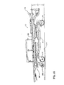
- the ambulance cot 10 is similar to the ambulance cots disclosed in U.S. Patent No. 5 537 700 and WO 2004/064698 , the subject matters thereof being incorporated herein by reference.
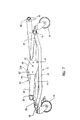
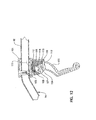
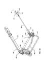
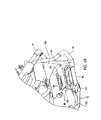
- the ambulance cot 10 includes a base frame 11 composed of longitudinally extending side rails 12 and crosswise extending rails 13 interconnected at the ends thereof to the side rails 12 to form a rectangle. Castered wheels 14 are operatively connected to each corner of the rectangle base frame formed by the rails 12 and 13.
- the ambulance cot 10 includes a litter 16 comprising a litter frame 17.
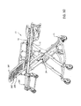
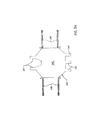
- An elevating mechanism 18 is provided between the base frame 11 and the litter frame 17 in order to facilitate a lifting and lowering of the litter 16 relative to the ground. More specifically, the elevating mechanism 18 includes a pair of side-by-side oriented "X" frames 19 and 21.
- the X frame 19 includes a pair of X frame members 22 and 23 connected together adjacent their midlength portions by means of a pivot axle 24.
- Each of the X frame members 22 and 23 is hollow and telescopingly receives therein a further X frame member 26 and an X frame member 27, respectively.
- the further X frame members 26 and 27 are supported for movement into and out of the respective X frame members 22 and 23.
- the distal end of the further X frame member 26 is secured via a connection 28 to the cross rail 13 at the left end (foot end) of the base frame illustrated in Figure 1 whereas the distal end of the further X frame member 27 is connected via a connection 29 to the cross rail 13 at the right end of the base frame 11.
- the X frame 21 is similarly constructed and includes a pair of X frame members 32 and 33 which are connected together at about their midlength portions by the aforesaid axle 24. While the axle 24 is illustrated to extend laterally between the X frames 19 and 21, it is to be understood that separate axles 24 can, if desired, be employed (as shown in Figure 50 ).
- the X frame members 32 and 33 are hollow and telescopingly receive therein a further X frame member 36 telescopingly received in the X frame member 32 whereas a further X frame member 37 is telescopingly received in the X frame member 33.
- the distal end of the further X frame member 36 is connected via a connector 38 to the cross rail 13 at the foot end of the base frame 11 and the distal end of the further X frame member 37 is connected via a connector 39 to the cross rail 13 at the head end of the base frame 11.
- the X frame members 22, 26 extend parallel to the X frame members 32, 36 whereas the X frame members 23, 27 extend parallel to the X frame members 33, 37.
- each of the linkage members 41 includes at the end thereof adjacent the cross rail 13 a bore 42 which encircles the cross rail 13 to facilitate the pivotal connection of each of the linkages 41 about the longitudinal axis of the cross rail 13.
- the ends of each of the linkages 41 remote from the cross rail 13 are connected to respective laterally spaced brackets 43 by means of a fastener 44.
- a sleeve 46 extends between the respective brackets 43 and receives therein the respective fastener 44 to facilitate the connection of the linkages 41 to the brackets 43.
- the axle 24 also facilitates a connection of the respective brackets 43.
- Each of the brackets 43 includes a receptacle 47 into which is received a respective X frame member 23 and 33 as illustrated in Figure 1 .
- the axle 24 passes through an opening provided in each of the respective X frame members 23 and 33.
- a first bracket 48 ( Figure 4 ) is fixedly secured to the cross rail 13.
- a second bracket 49 is secured to a rod 51 that is connected to and extends between the respective brackets 43.
- the rod 51 is connected to each bracket by a respective fastener 52. It is to be noted that there is a spacing between the axle 24 and the respective rods 46 and 51. The purpose of this spacing will become apparent below.
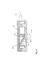
- At least one linear actuator 53 (two, if desired to provide improved stability) is connected to and extends between the respective brackets 48 and 49.
- the linear actuator 53 includes a hydraulic cylinder housing 54 fastened to the bracket 49, which cylinder housing 54 includes a reciprocal rod 56 having a piston (not illustrated) at one end thereof located within the cylinder housing 54.
- the distal end of the reciprocal rod 56 is connected in a conventional manner by a universal-like joint 55 to the bracket 48. That is, the universal joint allows pivotal movement about two orthogonally related axes.
- extension and retraction of the reciprocal rod 56 will facilitate movement of the brackets 43 about the axis of the rod 46.
- the end of the rod is lengthwise adjustable to accommodate tolerances encountered during production.
- the ends of the X frame members 22 and 32 remote from the base frame 11 are each pivotally secured to a cross rail 59 adjacent the head end of the litter frame 17 as at 57 and by respective connectors 58.
- the connectors 58 are each relatively movable with respect to the cross rail 59.
- the ends of the X frame members 23 and 33 remote from the base frame 11 are connected by a hollow pivot tube 61 via connectors 62. Only one of the connectors 62 is illustrated in Figure 6 , it being understood that the end of the X frame member 23 remote from the base frame 11 also has a connector 62 thereon.
- a slide bearing (not shown) can, if desired, be provided to allow longitudinal movement of the X frame member 33 along the litter rail 66.
- a timing rod 63 can be relatively rotatably received inside the pivot tube 61. Opposite ends of the timing rod 63 have a pinion gear 64 fastened thereto and rotatable therewith. The purpose of the timing rod and the pinion gear 64 oriented at the opposite ends thereof will become apparent below.
- the X frame members 23, 33 and the pivot tube 61 can be welded together to enhance the overall strength and resistance to twisting characteristics.
- the litter 16 comprises a litter frame 17 which consists of a pair of lengthwise extending side rails that are laterally spaced from one another, which side rails 66 are connected at the head end by the aforesaid cross rail 59, further cross rails 67 and other cross rails not illustrated.
- a housing 68 (see also Figure 6 ) is secured to the underside of each of the side rails 66 at a location spaced from the head ends thereof.
- Each housing 68 has an inwardly opening recess 69 therein, the openings in each of the housings 68 opposing one another.
- the openings 69 each have a downwardly facing upper wall 71 to which is secured a toothed rack 72 extending lengthwise of each of the respective side rails 66.
- the teeth of each of the pinion gears 64 are configured to mesh with the teeth of the toothed rack 72. Since the pinion gears 64 are fixedly secured to the timing rod 63, the mating teeth on the pinion gear 64 and the rack 72 will prevent twisting of the elevating mechanism 18 as it raises and lowers the litter 16 relative to the base frame 11.
- the longitudinally extending side rails 66 of the litter frame 17 are hollow.
- the cross rails 59 and 67 as well as others not specifically described are secured by brackets to the exterior surface of each of the side rails 66.
- Several of the brackets 71 are illustrated in Figure 5 .
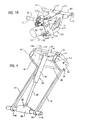
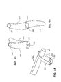
- a foot end lift handle mechanism 72 is illustrated in Figure 8 and consists of a pair of vertically spaced U shaped frame members 73 and 74.
- the legs of each of the U shaped frame members 73 and 74 are joined together by a bracket 76 (only one bracket being illustrated in Figure 8 ), which bracket 76 is fastened to the respective legs by fasteners not illustrated.
- Each bracket 76 is telescoped inside of the foot end of the respective side rail 66 as illustrated in Figure 1 .
- the legs of the lower frame member 74 diverge away from the legs of the frame member 73 so that there is provided pairs of vertically spaced hand grip areas as at 77 and 78 on the respective frame members 73 and 74, respectively.
- Plural spacer brackets 79 are connected to the bight portions of each of the frame members 73 and 74 to maintain the vertical spacing between the grip areas 77 and 78. Fasteners (not illustrated) facilitate a connection of the brackets 76 to the interior of each of the respective side rails 66.
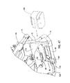
- a battery mount 89 is secured to the foot end lift handle assembly 72, preferably to the underside of the assembly as show in Figures 47 and 48 .
- the battery mount 89 includes a downwardly opening bayonet socket 90 having electrical contacts 94 exposed therein for connection to a properly configured battery 160 shown in broken lines.
- the manner in which the battery 160 connects to the electrical contacts 94 when the battery is in the broken line position shown in Figure 48 is conventional and, therefore, further discussion about this connection is believed unnecessary.
- the electrical contacts 94 on the battery mount 89 are connected to the control 158 as schematically shown in Figure 24 . In order to connect the battery 160 into place in the battery mount 89, the battery is moved leftwardly from the Figure 47 disconnected inactive position to the Figure 48 connected and active position.
- the battery 160 in the installed position of Figure 48 is releasably locked in place and is capable of withstanding excessive acceleration forces that will occur during an accident to remain locked in place in the Figure 48 position.
- One leg 81 of the frame member 73 includes a switch housing 82 fastened thereto by at least one fastener 83 ( Figure 9 ).
- the switch housing 82 is located in an ergonomically advantageous position to the obvious grasping point of the user.
- An enlarged isometric view of the switch housing 82 is illustrated in Figure 10 .
- the switch housing has a pair of manually engageable buttons 84 and 86 thereon.
- the manually engageable buttons 84 and 86 are shielded from above by a shroud 87 and are of a low profile membrane design so as to prevent inadvertent actuation of the buttons 84 and 86 by a patient lying on the upper surface of the litter 16. That is, the shroud 87 is oriented at the head end of the switch housing 82.
- the switch housing 82 includes an opening 88 extending therethrough and through which the leg 81 of the frame 73 extends.
- the fastener 83 extends through a hole in the leg 81 to facilitate a connection of the housing 82 to the leg 81 extending through the opening 88.
- the leg 91 of the frame member 74 includes a further switch housing 92, located in an ergonomically advantageous position to the obvious grasping point for the user, having an opening 98 extending therethrough and through which the leg 91 extends.
- a fastener 93 facilitates a connection of the switch housing 92 to the leg 91 that extends through the opening 98.
- the switch housing 92 includes a construction identical to the switch housing 82 illustrated in Figure 10 and it includes a pair of manually engageable buttons 84 and 86 which, as will be explained in more detail below, provide a redundant operation with respect to the buttons in the switch housing 82.
- the switch housing 92 also includes a shroud 97 similar to the shroud 87 and it is provided for the same purpose, namely, to shield the buttons 84, 86 from inadvertent actuation by a patient lying on the litter 16.
- a shroud 97 similar to the shroud 87 and it is provided for the same purpose, namely, to shield the buttons 84, 86 from inadvertent actuation by a patient lying on the litter 16.
- each of the push button switches 84, 86 have a dual switch closing feature requiring both switch contacts to be closed (see Figure 11 in order to effect the desired operation as will be explained in more detail below.
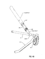
- a manually engageable handle 103 is pivotally secured to the bracket 102 by a pivot axle 104.
- the handle includes a pair of arcuately spaced shoulders 108 and 107.
- a cable support member 108 is pivotally secured to the bracket 101 by a pivot axle 109.
- a cable, here a Bowden cable 111 is fastened as at 112 to the cable support 108 (at one end) while the other end is fastened to a valve actuation device which will be explained in more detail below.
- the cable 111 extends into and through the hollow interior of the frame member 74.
- the cable support member 108 has a pair of arcuately spaced shoulders 113 and 114 that operatively cooperate with the arcuate shoulders 106 and 107, respectively, as will be explained in more detail below.
- the handle 103 as illustrated in Figure 12 is in a stowed out of the way position. When it is desired to move the handle and use it for operation of the ambulance cot, it is shifted clockwise in its position from the position illustrated in Figure 12 to the position illustrated in Figure 13 at which time the shoulder 107 engages the shoulder 114 on the cable support member 108.
- a torsional spring 116 (only the ends of which are illustrated in Figures 12-14 ) serves to continually urge the handle 103 counterclockwise to the stowed position so that the shoulders 106 and 113 will engage one another.
- each of the side rails 66 there is provided a pair of longitudinally spaced brackets 71 on each of the side rails 66. Between laterally spaced ones of the brackets 71, there extends a respective cross rail 67. Referring to Figure 15 , these cross rails 67 support a hydraulic assembly bracket 121. More specifically, the hydraulic assembly bracket 121 includes several ears 117 which operatively engage the respective cross rails 67 and from which ears is suspended the hydraulic assembly bracket 121.
- the hydraulic assembly bracket 121 is generally U shaped with the bight section forming a base upon which is mounted a variable speed electric motor 122, a hydraulic manifold plate 123 and a hydraulic pump 124.
- the hydraulic pump 124 has two outlets 126 and 127.
- the hydraulic outlets 126 and 127 are connected through hydraulic conduits 128, 129, respectively ( Figure 4 ), to respective opposite ends of the hydraulic cylinder housing 54.
- the cross rails 67 also provide a support for a seat section 130 ( Figure 1 ) on the litter 16.
- each connector includes a sleeve 118 that encircles the cross rail 13 and includes a stem 119 that is telescoped inside the interior of each of the respective further X frame members 26, 27, 36, 37.
- a bearing assembly 131 is provided between the stem 119 and the interior surface of the further X frame members 26, 27, 36, 37.
- the bearing assembly 131 will facilitate a relative rotation between the sleeve 118 and the further X frame members 26, 27, 36, 37.
- the bearing assembly 131 becomes particularly important when the X frame members 22, 23, 32, 33 are not circular in cross section and the further X frame members 26, 27, 36, 37 are circular in cross section (as depicted in Figure 49 ). That is, a bushing 236 is fixedly positioned inside the non-circular X frame members 22, 23, 32, 33, which bushing 236 has a circular opening therethrough through which the further X frame members 26, 27, 36, 37 slidably extend.
- the end of the further X frame members 26, 27, 36, 37 remote from the base 11 have a further bushing 237 longitudinally slidably disposed in the X frame members 22, 23, 32, 33.
- the bushing 237 is relatively moveably secured to the respective further X frame members 26, 27, 36, 37, such as through the use of a rivet and washer mechanism 238 being secured to the further X frame members 26, 27, 36, 37 on opposite sides of the bushing 237 so as to prevent a relative longitudinal movement of the bushing 237 along the length of the further X frame members and so that the further X frame members can rotate about their respective longitudinal axes relative to the bushing 237.
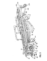
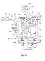
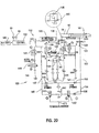
- a hydraulic circuit 132 is included in the manifold plate 123 ( Figure 15 ). It is to be understood that the pump 124 and the linear actuator 53 and the conduits carrying hydraulic fluid to the linear actuator 53 are preferably always filled with hydraulic fluid. Further, the pump 124 is reversible and the electric motor 122 driving same is also reversible. As a result, there will be no delay in actuation of the linear actuator in response to an operation of the pump 124 by the electric motor 122. The output of the pump 124, in one direction of operation, will supply hydraulic fluid through a pilot operated check valve 133 to the outlet 126 connected through the hydraulic conduit 128 to the end of the cylinder housing 54 remote from the reciprocal rod 56.
- Operation of the pump 124 in the opposite direction will direct fluid through a poppet valve 134 having in parallel therewith an orifice or fluid throttle 136 and a two way poppet valve 137 to the outlet 127 which in turn is connected through a conduit 129 to the end of the cylinder housing 54 adjacent the reciprocal rod 56.
- the fluid controlling the pilot operated check valve 133 is delivered to it through a conduit 138 connected to the fluid path intermediate the poppet valve 134 and the pump 124.
- a fluid passageway 142 extending to a series connected pressure compensated flow controller 143, a spring controlled check valve 144 and a two way poppet valve 146 connected to the tank 141.
- the spring is sized in this check valve so as to provide a dampening against a surge of fluid when passively lowering. This prevents a lurch in the lowering action providing increased comfort to the patient during lowering.
- the passageway 142 includes a further passageway 147 connected through a spring biased check valve 148 to tank 141, on the one hand and through a passageway 149 to a manual release valve 151 also connected to tank 141.
- the outlet 127 is connected through a passageway 152 to a spring biased check valve 153 connected to the tank 141, on the one hand, and through a passageway 154 to a series connected fluid throttle 156 and thence to a further manual release valve 157 connected to the tank 141.
- the hydraulic circuit 132 is controlled by a control mechanism 158, which control mechanism is also schematically represented in Figures 24 and 25 .
- a hydraulic fluid pressure monitoring mechanism 159 is connected to the outlet 126 and provides a signal indicative of the magnitude of the fluid pressure to the control mechanism 158.
- the battery 160 ( Figures 47 and 48 ) on board the ambulance cot provides power to the control mechanism 158.
- the charged status of the battery 160 is linked to a display 161 on a user interface 162 mounted on the foot end lift handle assembly 72 near the battery mount 89, particularly between the spacer members 79.
- the user interface 162 also includes a mode switch (not illustrated) for allowing the user interface to display a multitude of different functions, one of which can be an hour meter indicative of the total elapsed time that the electrical motor 122 has been operated, such as "HH:MM", where H is hour and M is minute or in tenths of an hour such as "HH.H hours". Any other indication of total elapsed time from a set point is contemplated.
- the user interface it is also possible for the user interface to display the elapsed amount of time that the control 158 has been on, the elapsed amount of time a certain switch is activated, the elapsed amount of time certain valves have been actuated or the elapsed amount of time a certain pressure has been maintained on the system.
- a symbol (preferably iconic) can be provided at preprogrammed interval(s) to indicate when service may be necessary.
- the control mechanism 158 also receives signals from position sensors provided on the ambulance cot. More specifically, and referring to Figure 26 , a cover 163 has been removed from the housing 68 to reveal the opening 69 inside the housing. A first transducer 164 is provided inside the opening 69, particularly at the foot end of the opening 69 whereas a second transducer 166 is oriented at the head end of the opening 69. These transducers 164 and 166 are, in this embodiment, Hall effect sensors which are used to indicate the low and high heights of the ambulance cot. Alternatively, proximity sensors or reed switches can be employed in place of the Hall effect sensors.
- transducers are adjustably positioned in the opening 69 such that they detect a magnetic field of a magnet mounted, for example, on one end of the pivot tube 61 ( Figure 5 ) or on the slide bearing thereat (not shown) and oriented on the outboard side of the pinion gear 64 or slide bearing located thereat.
- a magnetic field of a magnet mounted, for example, on one end of the pivot tube 61 ( Figure 5 ) or on the slide bearing thereat (not shown) and oriented on the outboard side of the pinion gear 64 or slide bearing located thereat.
- the pinion gear 64 approaches either one of the transducers 164 or 166
- the magnetic field of the magnet will saturate the respective transducer to create an appropriate signal to the control mechanism 158 that is indicative of the height position of the cot.
- the position of the transducers 164, 166 are variable lengthwise of the opening 69 so as to provide an ability to effect a height adjustment for the ambulance cot in both its collapsed and its uppermost position.
- a specific advantage of having a movable second transducer 166 is that the high height of the ambulance cot can be adjusted to provide a stopping point custom adjusted to a specific ambulance for ease of loading the cot into the ambulance.
- a further transducer 167 is provided adjacent the second transducer 166 so as to cause an additional signal to be sent to the control mechanism 158. This additional signal is supplied as feedback to the control mechanism 158 to subsequently control motor speed to effect a smooth stop of the litter 16 in the uppermost position.
- a further transducer 168 can be provided adjacent the first transducer 164 so as to cause a further signal in the form of feedback to be sent to the control mechanism 158 to effect a subsequent controlling of motor speed to effect a smooth stop of the litter 16 in the lowered position. This smooth stopping operation is provided for patient comfort.
- the control mechanism 158 also receives signals indicative of the presence of the ambulance cot inside the ambulance.
- an ambulance cot latching mechanism inside the ambulance includes a rod 169 that extends along one side of the ambulance cot and has adjacent its distal end 171 a bracket 172 which has a magnet 173 provided thereon.
- the magnet 173 becomes positioned adjacent a transducer (not shown) to send a signal to the control mechanism 158 to effect a total and complete deactivation of the hydraulic lift or lower operation capabilities of the hydraulic circuit.
- This transducer may optionally be the position transducer 164.
- Figures 28-30 are a bottom view of the manifold plate 123 having mounted thereon the reversible electric motor 122 and the reversible pump 124. If desired, the motor 122 could be driven in one direction and a transmission utilized to effect a reverse operation of the pump 124.
- the release valves 151 and 157 are mounted on the manifold plate 123.
- the release valve 151 includes a reciprocal stem 174 which, when moved to the right in the aforesaid figures, effects an opening of the valve to allow fluid flow to pass therethrough.
- the release valve 157 has a stem 176 which, when moved to the right in the aforesaid drawing figures, also effects an opening of the valve 157 to allow hydraulic fluid to pass therethrough.
- the orifice 156 may be sized to control the drop rate of the base 11 when the litter 16 is supported by an attendant or plural attendants.
- a plate 177 is provided and has holes therethrough which receive the respective stems 174 and 176 therethrough so that an appropriate fastener 178 can effect a fastening of the respective stems 174 and 176 to the plate 177.
- the cable 111 is connected to the plate as at 179. The opposite end of the cable 111 is connected to the release handle mechanism illustrated in Figures 12-14 .
- the release valves 151 and 157 each have a fluid chamber 181 therein into which hydraulic fluid directly from the outlet port 126 is fed through an inlet port 183.
- the valves 151 and 157 each have a reciprocal spool 184 therein, the movement of which is controlled by the tension applied to the stems 174, 176 by the cable 111.
- the spool 184 includes a land 186 having a valve seat surface 187 thereon which mates with a valve seat surface 188 provided on the body 189 of the release valve 151.
- a spring (not illustrated) serves to urge the valve seat surface 187 against the valve seat surface 188, especially when no fluid pressure is applied to the chamber 181.
- valves 151 and 157 will facilitate it being necessary that the ambulance cot attendants lift the cot prior to activation of the manual release valves 151 and 157 so that the fluid pressure in the chamber 181 will be reduced to facilitate a rightward movement of the spool 184.
- a conventional velocity fuse 192 ( Figure 17 ) is provided in the inlet port to the end of the cylinder housing 54 of the linear actuator 53, particularly at the end thereof remote from the reciprocal rod 56.
- the velocity fuse can also be an integral component of the cylinder housing 54.
- This conventional velocity fuse is Model No. 8506 available from Vonberg Valve, Inc. of Rolling Meadows, Illinois.
- the purpose of the velocity fuse is to prevent a rapid lowering of the cot when there is a sudden loss of hydraulic pressure as in the case of a severed hydraulic hose, or accidental manual release with a patient on the cot.
- a check-valve 195 is provided in parallel to the velocity fuse in order to affect an increased speed of extending of the base. This allows the same or similar speed in powered, and manual mode such that the manual mode may be used in normal use to extend the base when unloading the cot from the ambulance.
- the ambulance cot and load system electronics for facilitating a loading of the cot into an ambulance contain the capability to interact with a handheld diagnostics tool over a wireless communication link.
- This tool allows manufacturing and maintenance personnel to perform basic configuration, troubleshooting and complex diagnostic operations on both the cot and load system, while remaining free from physical cable attachment to either unit.
- An example of the functional descriptions for each of the elements involved in wireless diagnostics are set forth below.
- the handheld device or tool 300 ( Figure 34 ) is self contained, and includes an antenna 301, a wireless transmitter and receiver that operate under the same basic protocol as the wireless link connecting the cot and load system during normal operation. Operations such as collecting and configuring control parameters and initiating simple or complex diagnostics tests are supported through this interface.
- this handheld device is capable of four main modes of operation:
- Two-way active communication allows the handheld device to interact directly and exclusively with one cot (or one load system) in order to provide streamlined communication during programming or troubleshooting phases.
- Multi-way communication allows the handheld device to participate in communications with multiple other parties, and allows for more complex troubleshooting and diagnostics operations. For example, when a cot is docked in the load system and a handheld device is brought into proximity of the wireless communication field, it will be able to interact with both units to gather information or allow the user to invoke special tests to verify operation of the loading algorithm.
- the wireless diagnostic tool is capable of auto-detecting the proper mode in which to operate, which is based on the number of active participants it senses in the wireless communication field.
- the "listen only" mode is entered at the prompting of the user of the handheld device. This mode is passive in nature, and can be used to analyze communications coming from one unit (cot or load system), or multiple units which are in dialog with one another.
- the ambulance cot's electronic controller contains software components to support wireless diagnostics capabilities. This software functionality is capable of detecting the difference between a load system that is trying to communicate and a wireless handheld device that is trying to initiate a diagnostic session. As this determination is made, the cot is able to enter into either a normal session with the load system, a dedicated session with the handheld device (if no load system is present), or a three-way session that involves both the handheld device and the load system. In the latter case, the cot software allows normal operation of the loading sequence, while simultaneously supporting a specific set of diagnostics that are useful in troubleshooting the overall system.
- the load system's electronic controller is also capable of distinguishing between a basic communication session for loading and unloading, and a session which involves diagnostics operations. Using similar software components, the load system will participate in dedicated two-way communication with a handheld device, or allow the device to coexist during a load or unload operation with the cot being present. It is capable of detecting the difference between these various modes of operation, and react accordingly to provide the necessary functional behavior.
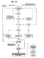
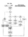
- Figures 32 and 33 provide a further description of the software functionality used in the wireless control and diagnostics features.
- the blocks entitled "Execute Configure Option” and “Transmit Wireless Response Message” include a read/write command to the RFID tag 302 (described below) when applicable in order to change the user statistics which may be coded on the RFID tag (Count of times programmer accessed, revision of software (if updated) etc).
- the load arm on the ambulance (see WO 2004/064698 , here in Figure 34 the load arm 194) includes a load arm antenna 196.
- the two antennas 193 and 196 provide communication between the cot and the load system as well as communication with the handheld unit.
- the antennas also provide a controlled communication envelope to allow any cot to communicate with any load system or handheld trouble shooting device while not interfering with other load systems/cots in the area.
- the cot antenna 193 ( Figure 34 ) consists of a loop of wire, as does the load antenna 196, and the tool antenna 301.
- the cot can be configured to selectively communicate with one of the load system and the tool through an active, inductive link; and power and one of read from and write to the RFID tag 302.
- the RFID tag 302 is useful in implementing the in-ambulance/in fastener shut-off feature (shown and described in more detail below) as well as for identifying the device for use with other specific RFID readers specifically as follows:
- This information may be used to configure the hand-held tool, or provide contact information for service.
- RFID tag 302 may be at least one of written to and read from the RFID tag 302 including at least one of the following: Model, Serial number of the unit, Software revision, and Usage statistics (which may include at least one of a count of different powered cots used with the system, and a count of times diagnostic tools accessed or changed the cot or load system(s)).
- the preamble is a special sequence to separate real data from the random noise.
- the preamble will contain special characters that are of 'illegal' length. This will cue the processor for a start of packet.
- the packet uses four bits for error correction (P0, P1, P2, P3).
- the error correction technique employs a Hamming code algorithm that will allow the processor to correct one bit that has been misinterpreted. Assuming a moderate bit error rate, the odds of a single bit being corrupted are relatively high while the odds of multiple bits being corrupted is relatively very low. Allowing for 1 bit to be corrected will result in an overall greater throughput at a relatively low cost of extra bits.
- the parity bit is an extra check to ensure data integrity.
- the parity bit is calculated using basic even parity checking; the parity bit is set so that the number of 1s in the packet will always be an even number.
- the parity bit will allow detection of a second bit error; however, it will not be able to correct it.
- the data bits communicate information about the cot status, an action request or diagnostic information.
- the most significant bit (D7) indicates whether the data is in diagnostic mode or not. If in diagnostic mode, remaining 7 bits indicate a diagnostic code or response. Otherwise each bit acts as an independent flag for a certain condition. If the transmission gets a response, the value is passed to the master controller; if no response is found, a value of '0'.
- Further software may be provided for the in-ambulance/in-ambulance shut-off feature when used with an RFID tag 302.
- the upper-level software diagram may look like that illustrated in Figure 59 .
- the cot upon power-up, the cot attempts communication with the load system in order to detect if it is present. If communication (com) is present, it executes function according to a specific and separate load protocol. If not, the cot communication will switch to check for the RFID tag. If it is not present, the cot drives according to the normal cot protocol. If the cot sees the RFID tag, it will then check for the low Hall Effect (HE) sensor (to determine if the cot legs are retracted). Once fully retracted, the cot inhibits driving (up), and thus activates the in-ambulance/in fastener shut-off feature.
- HE Hall Effect
- the ambulance cot 10 includes a retractable head section 197.
- This feature can be provided on a manual lift cot or a power lift cot.
- the retractable head section 197 is generally U shaped, namely, having a pair of parallel legs 198 and 199 connected by a pair of brackets 202 to a head rail 203.
- a cross brace 200 ( Figure 62 ) also connects the brackets 202.
- a tubular cross rail 201 is rotatably mounted to the cross brace 200.
- the legs 198 and 199 are configured to be slidably received by, into the interior of (shown), next to, or below the respective longitudinally extending side rails 66 on the cot 10.
- the handles 210 are fixed to the cross rail 201 for pivotal movement with the cross rail 201 about an axis corresponding to or parallel to the axis of the cross rail 201 in order to facilitate the movement of a pin 204 projecting from each handle 210 about an axis of rotation defined by or parallel to the axis of the cross rail 201.
- the pin 204 extends through an arcuate slot 215 in the bracket 202.
- the handles 210 are affixed such that actuation of one handle 210 effects a rotation of cross rail 201 and subsequent actuation of the other handle 210 so that the head section may be released by the actuation of a single handle 210.
- the pin 204 is connected by a linkage 206 to a latch mechanism 207 on each leg 198 and 199.
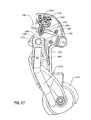
- the latch mechanism 207 is illustrated in more detail in Figures 42 and 43 . More specifically, the latch mechanism 207 includes a housing 208 in which a ramp mechanism 209 is slidably disposed lengthwise of the housing 208.
- the ramp mechanism 209 includes a ramp surface 211 against which a pin 212 rests.
- the pin 212 includes a latch pin 213 that is configured to move laterally into and out of the housing 208.
- the position located outside the housing is illustrated in Figures 37 and 42 .
- a spring (not illustrated) urges the pin 212 against the ramp surface 211.
- the pin 204 is moved from the position illustrated in Figure 39 to the position illustrated in Figure 40 to cause a leftward movement of the linkage 206 in each leg 198 and 199 to cause the pin 212 to shift in its position illustrated in Figure 42 to the position illustrated in Figure 43 , namely, a position wherein the latch pin 212 has been retracted laterally into the housing 208 of the latch mechanism 207.
- a slot 205 in the link 206 is provided which allows independent, passive engagement of the latch pins 213 when the handles 210 are released. This is illustrated in Figure 41 .
- a plurality of holes 214 are provided along the length of the side rails 66 and are configured to receive therein the latch pin 213 when in the extended position thereof as shown in Figure 37 . These holes are located such that access to them is not possible, i.e., under a bumper provided on the exterior of the litter rail 66. This is done for protection against inadvertent release, foreign matter, or potential pinching point.
- the handles 210 are capable of being locked against rotation about the cross rail 201 to prevent release of the latch mechanism 207.
- the safety bar 218 is fixed to a mounting bracket 260 that is pivotally mounted to the cross brace 200.
- the mounting bracket 260 is biased into an at rest position by a torsion spring 261 mounted on the cross brace 200 and engaging the mounting bracket 260 and the bracket 202.
- the mounting bracket 260 is configured so that the safety bar 218 can also be rotated upwardly in a clockwise fashion toward the interior of the cot, and function as a "latch disabler" to prevent release of the latch mechanism 207.
- a head portion 262 of the mounting bracket 260 is received on the cross brace 200.
- the head portion 262 is eccentrically configured about the cross brace 200 such that it includes a ramp portion 264 that extends toward the bracket 202 joining the leg 198 to the head rail 203.
- the mounting bracket 260 is arranged underneath a shaft 266 formed in the bracket 202.
- the shaft 266 is formed to extend into a central portion of the arcuate slot 215 that receives the pin 204 when the handle 210 is actuated.
- the shaft 266 is configured to received a pin 268 surrounded by a compression spring 270.
- the pin 268 and spring 270 are arranged in the shaft 266 so that the pin is biased out of the arcuate slot 215 by the spring 270.
- the pin 268 is held within the shaft 266 by the head portion 262 of the mounting bracket 260.
- the pin 204 is shown in the at rest position, that is wherein the handles 210 are not actuated.
- the pin 204 In order for the handles 210 to be actuated, the pin 204 must travel along the arcuate slot 215.
- the safety bar 218 has been rotated clockwise about the cross brace 200.
- the pin 268 rides along the ramp portion 264 of the mounting bracket 260.
- the ramp portion 264 is eccentrically configured, so that as the mounting bracket 260 rotates about the cross brace 200, the radius of the head portion 262 increases, forcing the pin 268 through the shaft 266 and into a blocking position in the arcuate slot 215 as when the safety bar slides over an existing cot fastening mechanism in an ambulance.
- the safety bar 218 can rotate so that the pin 268 blocks the arcuate slot 215, preventing the handles 210 from being actuated.
- Full engagement of the pin 268 occurs when the pin 268 reaches an end 269 of the ramp 264. This occurs prior to a stop 272 of the mounting bracket 260 abutting the shaft 266, which prevents further rotation of the safety bar 218.
- the torsion springs 261 are mounted one on each side of the safety bar 218, and act in torsion in opposing directions about cross brace 200, urging the brackets 260 and the safety bar 218 to a downward, neutral position, whereby the latch disabler is disengaged.
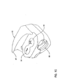
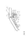
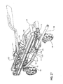
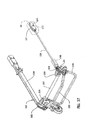
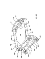
- the retractable head section 197 is configured to engage a portion of a cot fastening mechanism or "antler" system 276 configured for mounting to the floor of the cargo area of an ambulance.
- the antler system 276 includes a center yoke 278 and a forward yoke 280. Both yokes 278, 280 are mounted to the ambulance cargo area floor, with a centerline of the antler system 276 aligned in the fore-aft direction of the ambulance.
- the center yoke 278 is formed of two rods 282, 283 arranged as mirror images about the centerline of the antler system 276.
- Each rod 282, 283 includes a longitudinal segment 284, 285 and an outwardly divergent segment 286, 287, each outwardly divergent segment rising to a rearwardly directed hook or "ear" 288, 289.
- the forward yoke 280 includes a central segment 290 secured to the ambulance cargo floor and two outwardly divergent arms 291, 292. The arms each terminate in an "ear" 293, 294 that is joined with a respective ear 288, 289 of the center yoke 278.
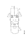
- the safety bar 218 contacts the center yoke 278.
- the center yoke 278 forces the safety bar 218 rearwardly until the safety bar 218 rides on top of the longitudinal segments 284, 285 of the rods 282, 283 of the center yoke 278.
- the latch disabler is activated prior to the stop 272 reaching the shaft 266.
- the longitudinal axis of the side rails 66 are inclined to the horizontal at an angle ⁇ (see Figure 35 ) that is in the range of 1 to 10°. In this embodiment, the preferred angle is in the range of 2 to 3°.
- the load wheels 216 are each rotatable about a fixed horizontal axis of rotation. That is, the wheels 216 are not supported in a castered manner.
- the head section 197 must be in the extended position of Figure 36 in order to be steered into the ambulance for engagement with the antler system 276.
- the retractable head section 197 includes a safety bar 218.
- the safety bar is configured to operatively engage a safety hook provided on the floor surface of a cargo area of an ambulance to prevent the cot from rolling completely out of the ambulance without an attendant being there to handle the head end of the cot.
- a modified safety bar 218A can be provided which is foldable between the folded position illustrated in Figure 45 and an unfolded position illustrated in Figure 46 .
- the safety bar 218A includes two sections 219 and 221 interconnected by a pivot axle 222.
- the safety bar sections 219 and 221 are approximately of the same length so that the pivot axle 222 is oriented at the midlength portion of the extended handle as is illustrated in Figure 46 .
- Releasable locking pins 223 are provided to lock the handle sections 219 and 221 in the respective folded position ( Figure 45 ) and the unfolded position ( Figure 46 ).
- a push button release or removable pin or other means of release (not illustrated) is provided for facilitating an activation of the locking pins to unlock them and facilitate relative movement between the handle sections 219 and 221.
- Figures 50-56 illustrate two accessories that can, if desired, be incorporated on the ambulance cot 10.
- the first accessory is depicted in Figures 50-51 and is a hook 239 oriented within the cot perimeter and which, specifically, is secured to the underside of the raisable and lowerable fowler 241 on the ambulance cot 10.
- the hook 239 consists of a sheet of material formed into a J with the stem of the J being secured to a cross rail 242 on the underside of the fowler 241 and the hook part 243 of the J facing toward the head end (left end) of the cot as depicted in Figures 50-51 .
- the hook 239 facilitates the hanging of various articles therefrom while the cot is in use.
- the second accessory is depicted in Figures 52-56 and is a collapsible pouch 244 secured to and extending between the legs 198, 199 of the head section 197 as well as to and extending between the cross rail 201 on the head section and the cross rail 59 ( Figure 5 ) on the litter frame 17.
- the pouch 244 consists of a planar sheet of fabric 237 to which are sewn plural fasteners 247 and 248 at spaced locations around the perimeter of the fabric sheet 246.
- the fasteners 247 are looped around the cross rails 59 and 201 while the fasteners 248 are looped around the laterally space legs 198 on the head section.
- the fabric sheet 246 is stretched between the longitudinally spaced cross rails 59 and 201 and laterally spaced legs 198 so as to provide a support surface 249.
- the cross rails 59 and 201 become closely adjacent one another and the fabric sheet 246 is collapsed in an accordion style therebetween.
- the further X frame members 32, 33, 36 and 37 will telescope outwardly to accommodate the changing height of the frame members 22 and 23 from the base 11.
- the pivot axle 24 for the two brackets 43 extend through the respective X frame members 22, 23 and 32, 33.
- a placement of the pivot axle 24 can be oriented at a location on the bracket 43 which will make it unnecessary to provide an axle receiving hole in each of the X frame members 23 and 33 as well as the elongate slots in the further X frame members 27 and 37.
- mounts 226 ( Figure 1 ) will operatively engage a cross rail provided on the underside of the litter 16 and additional mounts 227 will rest on the cross rail 13 on the base.
- the mounts 226 and 227 are oriented so that they are not readily accessible by attendants in the region of the ambulance cot and, therefore, pinching issues are avoided.
- each push button switch 84, 86 on the foot end lift handle assembly 72 requires two sets of switch contacts to be engaged in order to effect the desired command. That is, the set of contacts 228, 229 must both be closed in order to effect, for example, a retraction of the reciprocal rod 56 into the cylinder housing 54. Similarly, the two sets of contacts 231 and 232 of the switch 86 will effect an extension of the reciprocal rod 56 from the cylinder housing 54.
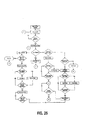
- the control will also make inquiry concerning whether the high top sensors 166 and 167 have been detected (see Figure 25 ) and, if not, the electric motor 122 is ramped in to effect a driving of the hydraulic pump 124. As soon as the motor reaches its maximum speed, the motor is continued to operate driving the pump at maximum speed until the sensor 167 is detected at which time the speed of the motor is ramped down or gradually slowed until the high top sensor 166 is detected, at which time the motor is brought to a stop. If the contacts 231 and 232 remain closed, the motor will remain stopped until the button 86 has been released by the attendant. Rapid uncontrolled deployment of the base from the Figure 3 position to the Figure 1 position is prevented by the orifice 136 in the valve 134 (Valve F). The attendant can thereafter "jog" the litter further upwardly by pressing the switch. In this case, the controller will activate the motor for a short interval of time, allowing incremental upward movement of the litter.
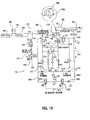
- FIG 19 illustrates a lowering of the litter from the Figure 1 position toward the Figure 3 position.
- the switch 84 is actuated to close the contacts 228 and 229 to cause an opening of the valve 146 (Valve B).
- Valve B the valve 146
- the hydraulic fluid enters the rod end of the linear actuator 53 by sucking same out of the tank 141 through a check valve 153. In this particular situation, operation of the motor 122 is not required and hence is not activated.
- the pressure switch 159 will detect the lifting by reason of a reduced pressure and as long as the switch 84 and the contacts 228 and 229 thereof remain closed, the motor 122 will be activated and driven in the opposite direction of rotation to effect a rapid driving of fluid into the rod end of the linear actuator 53 to rapidly collapse the cot.
- the Valve B Prior to this occurring, however, the Valve B will be returned to its initial position illustrated in Figure 17 as will Valve A.
- a separate switch (not shown) can be provided for effecting the same rapid collapse of the cot.
- a weep valve 233 is provided at the rod end of the cylinder housing 54 to cause a pressure relief to occur when the rod is fully extended. That is, hydraulic fluid inside the cylinder housing 54 will communicate with the outlet 127 to limit the pressure buildup inside the cylinder housing 54.
- the handle 103 and the valve 157 are allowed to operate, as Figure 12-14 and Figure 29 indicate.
- valve 151 Since the pressure is high in the chamber 181 of the valve 151, the valve 151 will not shift (as shown in Figure 29 ) in response to an operative movement of the handle 103 and the litter 16 of the cot 10 will not lower.
- the hydraulic pressure in the chamber 181 of the valve 151 is reduced to facilitate an easy movement of the land 186 and the valve seat surface 187 thereon ( Figure 31 ) away from the valve seat surface 188 in order to facilitate the operation of the valve 151 simultaneously with the valve 157 ( Figures 28-30 , particularly Figure 30 ).
- An ambulance cot comprising: a base frame; a litter frame; an elevating mechanism interconnecting said base frame and said litter frame and being configured to effect changes in elevation of said litter frame relative to said base frame, said elevating mechanism comprising a hydraulic circuit having an extendable and retractable hydraulic actuator, said elevating mechanism being connected to and extending between said base frame and said litter frame, a pump and a motor for driving said pump to effect a pumping of hydraulic fluid to said hydraulic actuator, said motor being energized from an electrical energy source; and a control mechanism, said control mechanism including a first set of manually operable electric controls for controlling a direction of hydraulic fluid flow to said hydraulic actuator to thereby facilitate movement of said litter frame at least one of toward said base frame and away from said base frame.
- control mechanism includes a second set of manually operable non-electric controls for overriding said first set of manually operable electric controls at least during a time interval wherein said electrical energy source is incapable of supplying electrical energy to said motor and said electric controls and for facilitating movement of said litter frame at least one of toward said base frame and away from said base frame in response to operation of said manually operable nonelectric controls.
- non-electric controls include at least one manually operable hydraulic valve having a reciprocal spool therein, said hydraulic valve being oriented in a conduit connect+-ng one end of said hydraulic actuator through said manually operable hydraulic valve to a tank, a weight of said cot and any load thereon causing a fluid pressure to exist at said one end of said hydraulic actuator and act through said conduit on said spool in said hydraulic valve to urge said spool in said hydraulic valve to a closed position.
- the ambulance cot wherein said manually operable hydraulic valve is configured to necessitate a removal of said fluid pressure before said spool can be manually moved through operation of said non-electric controls to open the connection through said conduit of said one end of said hydraulic actuator to a lower pressure part of said hydraulic circuit.
- the ambulance cot wherein said manually operable hydraulic valve is further configured so that said removal of said fluid pressure can only be accomplished by lifting said cot and any load thereon away from a support surface on which rests said base frame.
- said manually operable electric controls include a plurality of manually operable switches mounted on said litter frame adjacent said foot end thereof and configured to be readily accessible to an attendant oriented adjacent said foot end, and wherein said hydraulic circuit includes a plurality of hydraulic valves electrically operatively controlled by said manually operable switches.
- said manually operable electric controls include two sets of a plurality of manually operable switches mounted on said litter frame adjacent said foot end thereof and configured to be readily accessible to an attendant oriented adjacent said foot end as well as being configured to redundantly control the direction of hydraulic fluid, flow to said hydraulic actuator.
- the ambulance cot wherein said motor is a direct current motor and said electrical energy source is a battery.
- the ambulance cot wherein said hydraulic circuit includes a hydraulic fluid pressure sensing device oriented intermediate said pump and said hydraulic actuator and configured to provide a signal indicating at least one of the presence of a positive hydraulic fluid pressure and the absence of a positive hydraulic fluid pressure.
- said manually operable electric controls include a plurality of manually operable switches mounted on said litter frame adjacent said foot end thereof and configured to k>e readily accessible to an attendant oriented adjacent said foot end
- said hydraulic circuit includes a plurality of hydraulic valves electrically operatively controlled by said manually operable switches
- said control mechanism includes a processor responsive to manual operation of a selected one of said switches and being configured to effect a selective supply of electrical energy to said motor to effect a pumping of hydraulic fluid to said hydraulic actuator to change the elevation of said litter frame relative to said base frame.
- the ambulance cot wherein said plurality of manually operable switches includes two switches, a first switch for facilitating an increase in a spacing between said litter frame and said base frame and a second switch for facilitating a decrease in the spacing between said litter frame and said base frame.
- the ambulance cot wherein said motor is a direct current motor and said electrical energy source is a battery, said motor including a rotatably supported output shaft connected to a rotatably supported input shaft on said pump, said shafts being configured to be drivingly rotated in opposite directions of rotation, said processor being configured to separately supply electrical energy to said motor causing said motor to rotate in a first direction of rotation in response "to an operation of said first switch and supply electrical energy to said motor causing said motor to rotate in -a second direction of rotation in response to an operation, of said second switch.
- the ambulance cot wherein said hydraulic circuit includes a hydraulic fluid pressure sensor located intermediate said pump and said hydraulic actuator and configured to provide a first signal indicating a positive hydraulic pressure and a second signal indicating an absence of a positive hydraulic pressure, said processor being configured to monitor said first and second signals in response to an operation of said second switch.
- said hydraulic circuit includes a hydraulic fluid pressure sensor located intermediate said pump and said hydraulic actuator and configured to provide a first signal indicating a positive hydraulic pressure and a second signal indicating an absence of a positive hydraulic pressure, said processor being configured to monitor said first and second signals in response to an operation of said second switch.
- the ambulance cot wherein said. processor includes a ramp circuit for effecting a gradual change in the supply of electrical energy to said motor in response to an operation of at least one of said first and second switches to gradually change a speed of rotation of said shafts.
- the ambulance cot wherein said hydraulic circuit includes a first position detector configured to provide a third signal indicating a presence of said litter frame at a prescribed location relative to said base frame and a fourth signal indicating an absence of said litter frame at said prescribed location, said processor being configured to activate said ramp circuit in response to an activation of at least one of said first and second switches and in response to said fourth signal.
- said hydraulic circuit includes a hydraulic fluid pressure sensor located intermediate said pump and said hydraulic actuator and configured to provide a first signal indicating a positive hydraulic pressure and a second signal indicating an absence of a positive hydraulic pressure
- said processor being configured to monitor said first and second signals in response to an operation of said second switch, and wherein said hydraulic circuit includes a first position detector configured to provide a third signal indicating a presence of said litter frame at a prescribed location relative to said base frame and a fourth signal indicating an absence of said litter frame at said prescribed location, said processor being configured to activate said ramp circuit in response to an activation of said second switch and in response to said second and fourth signals.
- the ambulance cot wherein said hydraulic circuit includes a first position detector configured to provide a third signal indicating a presence of said litter frame at a prescribed location relative to said base frame and a fourth signal indicating an absence of said litter frame at said prescribed location, said processor being configured to activate said ramp circuit in response to an activation of said first switch and in response to said fourth signal.
- the ambulance cot wherein said hydraulic circuit includes a first position detector configured to provide a third signal indicating a presence of said litter frame at a first prescribed location relative to said base frame and a. fourth signal indicating an absence of said litter frame at said first prescribed location, and a second position detector configured to provide a fifth signal indicating a presence of said litter frame at a second prescribed location relative to said base frame and a sixth signal indicating an absence of said litter frame at said second prescribed location, said processor being configured to activate said ramp circuit to effect an increase in response to an activation of said first switch and said fourth and sixth signals, said processor toeing additionally configured to activate said ramp circuit to effect a decrease in the supply of electrical energy to said motor to gradually decrease the speed of rotation of said shafts in response to an operation of said first switch and said fourth and fifth signals.
- the ambulance cot further being configured to effect a jog function comprising a stopping of the motor in response to a continued operation of said first switch and said fourth and fifth signals, and to provide a short duration supply of electrical energy upon a release and reactivation of said first switch.
- the ambulance cot wherein said hydraulic circuit includes a first position detector configured to provide a third signal indicating a presence of said litter frame at a first prescribed location relative to said base frame and a fourth signal indicating an absence of said litter frame at said first prescribed location, and a second position detector configured to provide a fifth signal indicating a presence of said litter frame at a second prescribed location relative to said base frame and a sixth signal indicating an absence of said litter frame at said second prescribed location, said processor being configured to activate said ramp circuit to effect an increase in response to an activation of said second switch and said fourth and sixth signals, said processor being additionally configured to activate said ramp circuit to effect a decrease in the supply of electrical energy to said motor to gradually decrease the speed of rotation of said shafts in response to an operation of said second switch and said third and sixth signals.
- the ambulance cot further being configured to effect a jog function comprising a stopping of the motor in response to a continued operation of said second switch and said third and sixth signals, and to provide a short duration supply of electrical energy upon a release and reactivation of said second switch.
- a power lifting apparatus for adjusting the height of a patient supporting frame on an ambulance cot, the patient supporting frame having a head end and a foot end as well as a patient support deck with a top surface for holding a person, a base frame containing wheels, and an elevating mechanism for facilitating a varying of the height of said patient supporting frame relative to said base frame, said elevating mechanism comprising: an electric motor; a battery connected to said electric motor; an electric circuit for controlling said electric motor; a hydraulic fluid circuit comprising at least a hydraulic cylinder body having a reciprocal rod thereon and configured to effect said varying of the height of said patient supporting frame in response to relative movement between said hydraulic cylinder body and said reciprocal rod, said hydraulic cylinder body having first and second ports oriented adjacent opposite ends of said hydraulic cylinder body and through which hydraulic fluid can enter said hydraulic cylinder body; a hydraulic pump connected between said first and second ports and providing hydraulic fluid to said hydraulic cylinder body to effect movement of said reciprocal rod; and said electric motor drivingly connected to said hydraulic pump.
- said hydraulic pump has third and fourth ports, said hydraulic fluid circuit including a first conduit connecting said first and third ports and a second conduit connecting said second and fourth ports.
- said first conduit includes a third conduit connected to a first valve, said first valve providing an open or closed connection of said first conduit to tank through said third conduit.
- said second conduit includes a second valve, said second valve providing an open or closed connection between said second and fourth ports.
- said third conduit includes a flow controller for regulating a rate of hydraulic fluid flowing therethrough when said first valve is open to tank.
- said second conduit includes an orifice or fluid throttle connected in series with said second valve and is oriented between said second and fourth ports.
- said first conduit includes a pressure switch for monitoring hydraulic fluid pressure at said first port.
- said hydraulic fluid circuit includes a manual release circuit for connecting at least one of said first and second ports to tank.
- said manual release circuit includes a manually engageable handle mounted to said patient supporting frame adjacent one end thereof for easy access by an ambulance cot attendant.
- said hydraulic fluid circuit includes a manual release circuit for connecting said first and second ports to tank.
- said manual release circuit includes a manually engageable handle mounted to said patient supporting frame adjacent one end thereof for easy access by an ambulance cot attendant.
- said electric motor is a variable speed electric motor.
- the apparatus wherein there is provided a closed fluid flow circuit between said first and second ports and said pump and a fluid flow compensation circuit connected between said first and second ports and in parallel with said pump for regulating a first volume of fluid flow exiting from an end of said hydraulic cylinder body remote from said reciprocating rod to a second volume entering said pump so that said second volume through said pump is equal to an amount that enters said end of said hydraulic cylinder body whereat said reciprocating rod exits said hydraulic cylinder body.
- An ambulance cot comprising: a first frame; a second frame; an elevation mechanism interconnecting said first and second frames to facilitate moving said first and second frames toward and away from one another; and a timing device mounted on one of said first and second frames and configured to provide an indication of the elapsed time that said elevation mechanism has been operated.
- the ambulance cot wherein said elevation mechanism includes an electric motor, said timing device being configured for indication of the elapsed time that said electric motor has been operated.
- the ambulance cot wherein said timing device is configured to provide an iconic indication feature to indicate that service is needed to the cot.
- An ambulance cot comprising: a wheeled base; a patient litter disposed above said base; a support mechanism which supports said patient litter for vertical movement relative to said base, said support mechanism including elongate first and second support elements which each have first and second ends respectively pivotally coupled to said patient litter and to said base, which can each expand and contract in length, and which are pivotally coupled to each other at a locations between the ends thereof for pivotal movement about an approximately horizontal pivot axis, said support mechanism further including a fixed-length link member having a first end supported on said base for pivotal movement about a common axis with said second end of said first support element, and having a second end supported on said second support element at a location axially between said pivot axis and said second end thereof for pivotal movement about a further axis which is substantially parallel to said pivot axis; and an elevating system for selectively raising and lowering the patient litter, the elevating system having at least one extensible and retractable member with first and second ends, said first end being connected to the base for pivotal
- first and second support elements each include a tubular outer member having an upper end pivotally coupled to said patient litter, and an inner member telescopically slidably disposed within said outer member and having a lower end pivotally coupled to said base.
- the ambulance cot wherein said tubular outer member includes a non-circular cross-section and said inner member is received in a bushing within said tubular outer member for a low torque sliding connection.
- the ambulance cot wherein said second ends of said support elements pivotally supported on said base remain a predetermined distance from each other on said base in all operational positions of said support mechanism, and wherein said first and second support elements each telescope in length at locations between said pivot axis and said second ends thereof.
- each said inner member has means defining therein a slot which extends lengthwise thereof and transversely therethrough, and including an axle which extends along said horizontal pivot axis through said outer members of each of said first and second support elements and through said slots in said inner members thereof.
- each said inner member comprises an uninterrupted tubular member.
- said elevating system includes a hydraulic elevating system for selectively raising and lowering the patient litter, the hydraulic elevating system comprising a hydraulic pump and a hydraulic cylinder, the hydraulic cylinder having a first end connected to the base for pivotal movement about a common axis with said second end of said first support element and a second end pivotally supported on said second support element at a location axially between said pivot axis and said first end thereof for pivotal movement about a further axis which is substantially parallel to said pivot axis, said hydraulic elevating system further comprising selectively actuable locking means for releasably locking said support mechanism so as to respectively permit and prevent vertical movement of said patient litter relative to said base.
- the hydraulic elevating system comprising a hydraulic pump and a hydraulic cylinder, the hydraulic cylinder having a first end connected to the base for pivotal movement about a common axis with said second end of said first support element and a second end pivotally supported on said second support element at a location axially between said pivot axis and said first end thereof
- said support mechanism includes third and fourth elongate support elements which each have first and second, ends respectively pivotally coupled to said patient support and to said base, which can each expand and contract in length, and which are pivotally coupled to each other at locations between the ends thereof for pivotal movement about said horizontal pivot axis, said third and fourth support elements being spaced axially along said pivot axis from said first and second support elements, said first and third support elements pivoting about a common pivot axis at said first ends thereof and about a common pivot axis at said second ends thereof, and said second and fourth support elements pivoting about a common axis at said first ends thereof and about a common axis at said second ends thereof, said support mechanism further including a second fixed-length link member: having a first end supported on said base for pivotal movement about a common axis with said second end of said third support element, and having a second end supported on said second support element at a location axially between said pivot axis and said second end thereof for pivotal movement about a
- the ambulance cot wherein said upper end of said tubular outer members of one of said first and second elongate support elements and one of said third and fourth elongate support elements are pivotally mounted to a timing rod movable on said patient litter parallel to said pivot axis, the timing rod including a pinion gear mounted on each end for rotation therewith, and said patient litter further comprises a pair of toothed racks each configured for engagement by one pinion gear of the timing rod.
- the ambulance cot wherein said patient litter includes a frame having a fixed member and includes a movable member which is movably supported on said frame, wherein said first end of said first support member is pivotally supported on said fixed member and said first end of said second support member Ls pivotally supported on said movable member.
- An ambulance cot comprising: a wheeled base; and a patient litter disposed above and supported for adjustable vertical movement on said base by a support mechanism, the patient litter comprising: a pair of Longitudinally extending side rails, the side rails configured to extend from a head end to a foot end of the patient litter; a retractable, generally U-shaped head section, the head section having a pair of parallel legs connected by a cross rail, the legs being configured to be slidably received into trie interior of the respective longitudinally extending side rails, a pair of brackets connecting the 3_egs to a head rail, a cross rail pivotally received by the brackets, at least one handle pivotally mounted for movement about an axis corresponding to or parallel to the axis of the cross rail, the handle being connected to a pin configured for rotation about the axis of rotation defined by or parallel to the axis of the cross rail.
- the ambulance cot wherein the at least one handle comprises first and second handles, the first and second handles being affixed to the cross rail such that actuation of either of the first and second handles effects a rotation of the cross rail and actuation of the other handle.
- the ambulance cot further comprising a locking mechanism for selectively fixing the position of the head section in one of an extended and a retracted position, the locking mechanism configured for actuation by the first and second handles.
- the ambulance cot further comprising a locking mechanism deactivation mechanism for preventing the locking mechanism from becoming disengaged by "the actuation of the first or second handle.
- the ambulance cot further comprising the safety bar being configured to engage the locking mechanism deactivation mechanism.
- the ambulance cot further comprising a pin extending from each handle into the interior of a respective bracket for engaging a first end of a locking mechanism linkage, the linkage having a second end for engaging the locking mechanism, the locking mechanism comprising a retractable pin configured to engage one of a plurality of receivers within the side rail for fixing the position of the head section relative to the side rail.
- the ambulance cot wherein the plurality of receivers within the side rail are covered so as to be inaccessible from outside the side rail.
- the ambulance cot further comprising the head section including a pair of steering wheels.
- the ambulance cot further comprising the steering wheels being mounted for rotation about a fixed axis (i.e. non-castered) .
- the ambulance cot further comprising the steering wheels being mounted such that they are in contact with the ground only when the litter is in the lowered position and the head section is in the extended position to create a "steer" condition.
- the ambulance cot further comprising the patient litter being supported by the support mechanism at an angle x relative to a support surface, the angle x being between 1°-10°.
- the ambulance cot further comprising the head section including a pair of steering wheels mounted such that they are in contact with the ground only when the litter is in the lowered position and the head section is in the extended position.
- An ambulance cot comprising: a wheeled base; a patient litter disposed above said base; a support mechanism which supports said patient litter for vertical movement relative to said base, said support mechanism including elongate first and second support elements which each have first and second ends respectively pivotally coupled to said patient litter and to said base, which can each expand and contract in length, and which are pivotally coupled to each other at locations between the ends thereof for pivotal movement about an approximately horizontal pivot axis, said support mechanism further including a fixed-length link member having a first end supported on said base for pivotal movement about a common axis with said second end of said first support element, and having a.
- a hydraulic elevating system for selectively raising and lowering the patient litter, the hydraulic elevating system comprising an electrically operated hydraulic pump and a hydraulic cylinder, the hydraulic cylinder having a first end connected to the base for pivotal movement about a common axis with said second end of said first support element and a second end pivotally supported on said second support element at a location axially between said pivot axis and said first end thereof for pivotal movement about a further axis which is substantially parallel to said pivot axis; and a control system for said hydraulic elevating system, said control system comprising a first switch assembly and a second switch assembly, the first and second switch assemblies being electrically connected to the control system, each of the first and second switch assemblies comprising at least two operating buttons for raising and lowering the patient litter respectively, the first and second switch assemblies being physically remote from one another.
- the ambulance cot wherein the switch assemblies are configured to require actuation of two switch contacts to effect a raising or lowering of the patient litter.
- the ambulance cot wherein the switch assemblies are configured to enable actuation of the two switch contacts simultaneously by manual actuation of a single operating button.
- the ambulance cot wherein the two switch contacts are contained in a single membrane-style button, configured such that light depression of the button actuates a first of the two switch contacts to initiate a power on condition of the ambulance cot and full depression of the button actuates a second of the two switch contacts to initiate the raising or lowering of the patient litter.
- the ambulance cot, the first and second switch assemblies each further comprising a shroud shielding the buttons from inadvertent actuation.
- the ambulance cot, the first and second switch assemblies further comprising low profile membrane design buttons.
- An ambulance cot comprising: a wheeled base; and a patient litter disposed above and supported for adjustable vertical movement on said base by a support mechanism, the patient litter comprising: a pair of longitudinally extending side rails, the side rails configured to extend from a head end to a foot end of the patient litter; a retractable, generally U-shaped head section, the head section having a pair of parallel legs connected by a cross rail, the legs being configured to be slidably received by the respective longitudinally extending side rails, and at least one handle pivotally mounted for movement about an axis of the cross rail, a latch mechanism for selectively fixing the position of the head section in at least one of an extended and a retracted position, the latch mechanism configured for operation by the at least one handle, and a latch disabler configured to prevent the operation of the latch mechanism by the at least one handle.
- the ambulance cot further comprising a safety bar connected by a mounting bracket for pivotal movement about the axis of the cross rail, the mounting bracket including a head portion eccentrically disposed about the axis of the cross rail.
- the ambulance cot the head portion further comprising a ramp portion configured for displacing a blocking pin within one of the parallel legs to block the link pin.
- the ambulance cot further comprising a first handle and a second handle, each associated with a respective parallel leg and corresponding latch mechanism within the respective parallel leg.
- the ambulance cot further comprising a pair of latch disablers, each associated with a respective parallel leg, handle and latch mechanism.
- the ambulance cot the first and second handles being affixed to the cross rail such that actuation of either of the first and second handles effects a rotation and actuation of the other handle.
- the ambulance cot further comprising the handle including a link pin extending into the interior of a respective leg for engaging a first end of a latch mechanism linkage, the linkage having a second end for engaging the latch mechanism, and the latch mechanism comprising a retractable latch pin configured to engage one of a plurality of receivers within the side rail for fixing the position of the head section relative to the side rail.
- the ambulance cot further comprising the latch disabler preventing the movement of the handle about the axis of the cross rail by blocking the link pin.
- An ambulance cot comprising: a base frame; a litter frame; an elevating mechanism interconnecting said base frame and said litter frame and being configured to effect changes in elevation of said litter frame relative to said base frame; and a control mechanism including a cot antenna and a separate tool configured for at least one of cot programming, remote control and cot diagnostics and having a tool antenna, said control mechanism and said tool being configured for wireless communication so that said tool can execute diagnostic analysis of said control mechanism and report the results thereof.
- the ambulance cot wherein said litter frame includes a patient support deck having a head section, a seat section and a foot section, said cot antenna being oriented beneath said seat section.
- a combination of an ambulance cot and a load system onboard an ambulance for facilitating a loading and unloading of said ambulance cot comprising: said ambulance cot including a base frame, a litter frame and an elevating mechanism interconnecting said base frame and said litter frame and being configured to effect changes in elevation of said litter frame relative to said base frame, said elevating mechanism comprising an extendable and retractable actuator connected to and extending between said base frame and said litter frame, an onboard control circuit for controlling an operation of said extendable and retractable actuator; said load system onboard said ambulance having thereon a load system control circuit and a device for effecting a coupling of said ambulance cot to said load system; a cot antenna mounted on said ambulance cot and connected in circuit with said onboard control circuit; a load system antenna mounted on said ambulance and connected in circuit with said load system circuit; and a separate tool configured for at least one of cot programming, remote control and cot diagnostics and load system diagnostics, said tool having a tool antenna, said tool being configured for wireless communication so that said tool can execute at
- said litter frame includes a patient support deck having a head section, a seat section and a foot section, said cot antenna being oriented beneath said seat section, and wherein said load system further comprises a trolley, said load system antenna being oriented on said trolley.
- said trolley includes a load arm having said device thereon for facilitating a coupling of said load arm to said ambulance cot, wherein said load system antenna is oriented on said load arm.
- An ambulance cot comprising: a base frame; a litter frame; an elevating mechanism interconnecting said base frame to said litter frame and being configured to effect changes in elevation of said litter frame relative to said base frame; a motor for driving said elevating mechanism; a computerized control system for monitoring a state of said cot and regulating operation of said motor, said control system including a transceiver configured to communicate data concerning said cot with a computerized monitoring and diagnostic system; and an electrical energy source for energizing said motor and said computerized control system.
- the ambulance cot wherein said motor is one of an electrical motor, a hydraulic pump, and a pneumatic pump.
- the ambulance cot wherein said computerized control system further includes memory for retaining operation and usage statistics concerning said cot.
- the ambulance cot wherein said computerized control system further includes a user interface configured to display at least one of a monitored state of said cot and usage statistic of said cot.
- the ambulance cot wherein said computerized monitoring and diagnostic system comprises a separate tool that can be selectively configured to monitor at least one operating state of said cot and conduct diagnostic tests on said cot.
- the ambulance cot wherein said tool includes a transceiver configured to wirelessly communicate data with said cot computerized control system.
- the ambulance cot wherein said tool operates in one of a variety of modes, including: a passive mode whereby said tool observes wireless communication activity between said cot computerized control system and a second wireless device; a two-way active communications mode, whereby said tool interacts with said cot computerized control system; and a multi-way active communications mode whereby said computerized tool interacts with at least two cot computerized control systems, or interacts with at least one cot computerized control system and a second wireless device.
- a passive mode whereby said tool observes wireless communication activity between said cot computerized control system and a second wireless device
- a two-way active communications mode whereby said tool interacts with said cot computerized control system
- a multi-way active communications mode whereby said computerized tool interacts with at least two cot computerized control systems, or interacts with at least one cot computerized control system and a second wireless device.
- the ambulance cot wherein said tool is configured to automatically enter a predetermined monitoring mode or diagnostic mode based upon: a type of data wirelessly detected by said tool; a number of active participants wirelessly detected by said tool; or a combination of type of data wirelessly detected by said tool as well as number of active participants wireless detected by said tool.
- the ambulance cot wherein said cot computerized control system wirelessly transmits a series of digital signals, with each said signal comprising a predetermined number of bits.
- the ambulance cot wherein said predetermined number of bits include at least one bit for error correction and a plurality of bits representing cot data.
- the ambulance cot wherein at least a portion of said predetermined number of bits represents a diagnostic code when said cot computerized control system operates in a diagnostic mode; and wherein each individual bit of at least a portion of said predetermined number of bits acts as an independent flag representing a specific state or condition of said cot when said cot computerized control system operates in a monitoring mode.
- An ambulance cot system for facilitating the transport of a patient, comprising: a cot for supporting and transporting said patient to and from an ambulance, said cot comprising: a base frame, a litter frame, an elevating mechanism interconnecting said base frame to said litter frame and being configured to effect changes in elevation of said litter frame relative to said base frame, a motor for driving said elevating mechanism, a computerized control system for monitoring a state of said cot and regulating operation of said motor, said control system including a transceiver configured to wirelessly communicate data concerning said cot, and an electrical energy source for energizing said motor and said computerized control system; a load system mounted upon an interior surface of said ambulance and configured to selectively secure said cot within said ambulance, said load system comprising: a guide track for guiding movement of said cot into and out of said ambulance, a device for securing said cot relative to said guide track, and a load system control circuit for selectively monitoring and controlling one or more states of said load system, said load system control circuit including a trans
- the ambulance cot system wherein said motor is one of an electrical motor, a hydraulic pump, and a pneumatic pump.
- the ambulance cot system wherein said cot computerized control system further includes a user interface configured to display at least one of a monitored state of said cot and usage statistic of said cot.
- the ambulance cot system wherein said tool operates in one of a variety of modes, including: a passive mode whereby said tool observes wireless communication activity between said cot computerized control system and said load system control circuit/ a two-way active communications mode, whereby said tool interacts with one of said cot computerized control system and load system control circuit; and a multi-way active communications mode whereby said computerized tool interacts with at least two cot computerized control systems, or interacts with at least one cot computerized control system and at least one load system control circuit.
- modes including: a passive mode whereby said tool observes wireless communication activity between said cot computerized control system and said load system control circuit/ a two-way active communications mode, whereby said tool interacts with one of said cot computerized control system and load system control circuit; and a multi-way active communications mode whereby said computerized tool interacts with at least two cot computerized control systems, or interacts with at least one cot computerized control system and at least one load system control circuit.
- the ambulance cot system wherein said tool is configured to automatically enter a predetermined monitoring mode or diagnostic mode based upon: a type of data wirelessly detected by said tool; a number of active participants wirelessly detected by said tool; or a combination of type of data wirelessly detected by said tool as well as number of active participants wireless detected by said tool.
- the ambulance cot system wherein at least one of said cot computerized control system and load system control circuit wirelessly transmits a series of digital signals, with each said signal comprising a predetermined number of bits.
- the ambulance cot system wherein said predetermined number of bits include at least one bit fox error correction and a plurality of bits representing either cot data or load system data.
- the ambulance cot system wherein at least a portion of said predetermined number of bits represents a diagnostic code when said cot computerized control system or load system control circuit transmitting said signal operates in a diagnostic mode; and wherein each individual bit of at least a portion of said predetermined number of bits acts as an independent flag representing a specific state or condition of said cot or load system when said cot computerized control system or load system control circuit transmitting said signal operates in a monitoring mode.
- An ambulance cot comprising: a base frame; a litter frame; and an X-frame support mechanism interconnecting said base frame and said litter frame and being configured to support said litter frame in one of a plurality of positions relative to said base frame, said support mechanism including at least one pair of frame members pivotally secured to each other proximate the mid-length thereof, said frame members each having opposite ends respectively secured to one of said base frame and said litter frame, at least one of said pair of frame members having a first mount oriented between said mid-length thereof and said base, said at least one of said pair of frame members having a second mount oriented between said mid-length thereof and said litter frame, said first and second mounts being configured to respectively engage said base frame and said, litter frame in response to said litter frame becoming proximate said base frame.
- An ambulance cot comprising: a base frame; a litter frame; and an elevating mechanism interconnecting said base frame and said litter frame and being configured to effect changes in elevation of said litter frame relative to said base frame, said elevating mechanism being configured to detect a presence and an absence of a force urging a change in elevation of said litter frame relative to said base frame to cause said base frame and said litter frame to become oriented closer together.
- An ambulance cot comprising: a base frame; a litter frame; and an elevating mechanism interconnecting said base frame and said litter frame and being configured to effect changes in elevation of said litter frame relative to said base frame, said elevating mechanism including at least one pair of frame members pivotally secured to each other proximal the mid-length thereof to form a X-frame, said frame members each having opposite ends respectively secured to one of said base frame and said litter frame, an end of said frame members adjacent at least one of said base frame and said litter frame including thereon a rotational pivot mechanism having an axis of rotation that extends co-extensively with a longitudinal axis of said frame member, said rotational pivot mechanism being configured to pivotally connect said frame members to said base frame so that relative movement between said base frame and said frame members occurs about said axis of rotation.
- An ambulance cot comprising: a base frame; a litter frame; an elevating mechanism interconnecting said base frame and said litter frame and being configured to effect changes in elevation of said litter frame relative to said base frame; and a control system for said elevating mechanism, said control system comprising a first switch assembly and a second switch assembly, said first and second switch assemblies being electrically connected to said control system and configured to be functionally redundant of one another, each of said first and second switch assemblies comprising at least two operating buttons for raising and lowering said litter frame respectively.
- the ambulance cot wherein said first and second switches are physically remote from one another and mounted on a foot end of said litter frame.
- An ambulance cot comprising: a base frame; a litter frame; an elevating mechanism interconnecting said base frame and said litter frame; a first control system configured to effect changes in distance between said litter frame and said base frame; and a second control system comprising a manually engageable handle operatively connected to said elevating mechanism and configured to usurp said first control system and only effect at least one of an increase and a reduction in distance between said litter frame and said base frame.
- the ambulance cot wherein said elevating mechanism includes a cot low height detection mechanism oriented adjacent an end of travel of said elevating mechanism.
- An ambulance cot comprising: a base frame; a litter frame; an elevating mechanism interconnecting said base frame and said litter frame and being configured to effect changes in distance between said litter frame and said base frame, said elevating mechanism including an adjustable height limiting mechanism for facilitating a customized in-ambulance adjustment of the height of said litter frame relative to said base frame to correspond to a configuration of an ambulance with which said ambulance cot is being used.
- said adjustable height limiting mechanism includes a cot low height detection mechanism oriented adjacent an end of travel of said elevating mechanism.
- the ambulance cot wherein said cot low height detection mechanism is a limit switch.
- the ambulance cot wherein said cot low height detection mechanism is a. Hall effect mechanism.
- the ambulance cot wherein said cot low height detection mechanism is a. programmable LVDT mechanism.
- An ambulance cot comprising: a base frame; a litter frame; a variable speed elevating mechanism interconnecting said base frame and being configured to effect changes in distance between said litter frame and said base frame, said elevating mechanism including a first adjustable height detecting mechanism for facilitating a customized adjustment of the height of said litter frame relative to said base frame, said elevating mechanism additionally having a second adjustable height detecting mechanism oriented intermediate said first adjustable height detecting mechanism and a remote end of travel location of said elevating mechanism and being configured to effect a change in speed of said variable speed elevating mechanism.
- the ambulance cot wherein said first adjustable height mechanism is oriented adjacent an end of travel of said elevating mechanism and is configured to effect a halting of movement of said elevating mechanism, and wherein said second adjustable height mechanism is configured to effect a slowing of said speed of said variable speed elevating mechanism.
- An ambulance cot comprising: a base frame; a litter frame; an elevating mechanism interconnecting said base frame and said litter frame and being configured to effect changes in distance between said litter frame and said base frame, said elevating mechanism including at least one of a variable and a selectable multiple speed drive mechanism for facilitating a driving of a change in distance operation at variable speeds, said elevating mechanism additionally including a cot height detection mechanism oriented adjacent an end of travel of said elevating mechanism and being configured to ramp down the speed of operation of said drive mechanism.
- the ambulance cot wherein said cot height detection mechanism includes at least one limit switch.
- the ambulance cot wherein said cot height detection mechanism is a Hall effect mechanism.
- the ambulance cot wherein said cot height detection mechanism is a programmable LVDT mechanism.
- said cot height detection mechanism includes a plurality of spaced sensors each configured to effect a change in speed of operation of said drive mechanism, a first of said sensors being configured to selectively slow the speed of operation while a second of said sensors being configured to halt the speed of operation.
- the ambulance cot wherein said first and second sensors are proximity switches.
- the ambulance cot wherein said first and second sensors are Hall effect sensors.
- An ambulance cot comprising: a base frame; a litter frame; an elevating mechanism interconnecting said base frame and said litter frame and being configured to effect changes in elevation of said litter frame relative to said base frame, said elevating mechanism including a variable speed drive mechanism for facilitating a driving of a change in elevation operation at variable speeds, said elevating mechanism additionally including a control circuit configured to ramp up the speed of operation of said variable speed drive mechanism to cause a smooth acceleration of said change in elevation operation.
- a combination of an ambulance cot and an ambulance having a cargo area comprising: a base frame and a litter frame on said ambulance cot; an elevating mechanism interconnecting said base frame and said litter frame and being configured to effect changes in elevation of said litter frame relative to said base frame; and an in-ambulance device configured to operatively detect a presence and absence of said ambulance cot in said cargo area, a component of said cot being configured to operatively couple with said in-ambulance device to deactivate said elevating mechanism.
- said component of said cot is said elevating mechanism that includes at least one cot height detection mechanism configured to deactivate said elevating mechanism solely in response to said cot being operatively coupled in said in-ambulance device.
- said in-ambulance device includes a magnet
- said cot height detection mechanism is a Hall effect sensor configured to detect the presence and absence of said magnet.
- said Hall effect sensor is a cot low height detection sensor.
- a combination of an ambulance cot and a load system onboard an ambulance for facilitating a loading and unloading of said ambulance cot comprising: said ambulance cot including a base frame, a litter frame and an elevating mechanism interconnecting said base frame and said litter frame and being configured to effect changes in distance between said base frame and said litter frame, said elevating mechanism comprising an extendable and retractable actuator connected to and extending between said base frame and said litter frame, an onboard control circuit for controlling an operation of said extendable and retractable actuator; said load system onboard said ambulance having thereon a load system control circuit and a device for effecting a coupling of said ambulance cot to said load system; a cot antenna mounted on said ambulance cot and connected in circuit with said onboard control circuit; and a load system antenna mounted on said ambulance and connected in circuit with said load system circuit said onboard control circuit being configured for a first mode of operation when communication between antennas is present and a second mode of operation when communication between antennas is not present.
- said load system includes a radio frequency identification device oriented within a communication envelop defined between said cot antenna and said load system antenna, said onboard control circuit being configured to be responsive to communication received from said radio frequency identification device that results from said radio frequency identification device communicating with said cot antenna.
- radio frequency identification device configured to record diagnostic/statistics relating to an interface between said load system and said cot.
- An ambulance cot comprising: a base frame; a litter frame; an elevating mechanism interconnecting said base frame and said litter frame and being configured to effect changes in elevation of said litter frame relative to said base frame, said elevating mechanism comprising a hydraulic circuit having an extendable and retractable hydraulic actuator, said elevating mechanism being connected to and extending between said base frame and said litter frame, and a drive mechanism coupled through conduits to said hydraulic actuator for effecting a pumping of hydraulic fluid to said hydraulic actuator; and a velocity fuse device connected in circuit with said hydraulic actuator and through which hydraulic fluid flows to at least one of extend and retract said extendable and retractable hydraulic actuator, said velocity fuse being configured to permit a maximum hydraulic fluid flow rate in an event of a ruptured conduit to thereby regulate a speed of at least one of extension and retraction of said extendable and retractable hydraulic actuator to thereby regulate a speed of descent of said litter frame toward said base frame.
- An ambulance cot comprising: a base frame and a litter frame; a deployment mechanism interconnecting said base frame and said litter frame and being configured to effect changes in distance between said litter frame and said base frame, said deployment mechanism having a detection device configured to detect a presence and an absence of a force urging a change in distance between said litter frame and said base frame to cause said base frame and said litter frame to become oriented closer together; and a control mechanism on said ambulance cot, said control mechanism including a manually operable device for controlling said deployment mechanism, said control mechanism being configured to effect a rapid movement of said deployment mechanism in response to said detection device detecting an absence of said force and in response to an operation of said manually operable device, whereby when said ambulance cot is lifted away from a support surface, causing said detection device to detect an absence of said force, and said manually operable device is operated, said base frame will be rapidly drawn toward said litter frame by said deployment mechanism.
- the ambulance cot wherein said deployment mechanism includes a hydraulic element and said detection device is further configured to detect a change in pressure of a hydraulic fluid in the hydraulic element.
- the ambulance cot in combination with an ambulance having a cargo area, the ambulance comprising a loading mechanism configured to couple to said ambulance cot and lift said ambulance cot away from the support surface, the movement of said base frame away from said support surface causing said detection device to detect the absence of said force.
- An ambulance cot comprising: a base frame; a litter frame adjustably supported on said base frame and including an extendable and retractable head section; and a pouch mounted on said extendable and retractable head section.
- the ambulance cot further comprising the pouch being further mounted to said litter frame and collapsible as said head section is placed in a retracted position.
- An ambulance cot comprising: a base frame; a litter frame adjustably supported on said base frame and including a fowler pivotally connected thereto; and an accessory hook mounted to said fowler.
- the ambulance cot further: comprising the accessory hook being mounted to an underside of the fowler for access with the fowler in a raised position.
- the ambulance cot wherein said accessory hook is configured to orient objects thereon within a perimeter of said cot.
- the ambulance cot further: comprising an extendable and retractable head section, and a collapsible pouch connected between the litter frame and the head section, wherein the accessory-hook is suspended over the pouch with the head section in an extended position.
- An ambulance cot comprising: a base frame; a litter frame; an elevating mechanism interconnecting said base frame and said litter frame and being configured to effect changes in elevation of said litter frame relative to said base frame, said elevating mechanism comprising a hydraulic circuit having an extendable and retractable hydraulic actuator, said elevating mechanism being connected to and extending between said base frame and said litter frame, and a drive mechanism coupled through conduits to said hydraulic actuator for effecting a pumping of hydraulic fluid to said hydraulic actuator; and said hydraulic actuator having a cylinder body and a piston, movably supported in said cylinder body, said piston having an elongate rod mounted thereto for movement therewith; a weep - valve and a connection connecting an interior of said cylinder body to a port on said hydraulic body that is adjacent an end of said cylinder body that said elongate rod exits said cylinder body, said connection being oriented on a side of said piston oriented at said end remote from said end so that when said piston is at said end, hydraulic fluid will be permitted to flow from said interior of said elev
- An ambulance cot and docking (antler) system comprising: an ambulance cot having an extendable and retractable -head end, a latch mechanism for selectively releasing said head end for movement between a retracted position and an extended position, and a pair of steering wheels rotatably mounted to the head end; and a docking system configured for mounting to an ambulance cargo area floor and configured for receiving the ambulance cot between a pair of outwardly and rearwardly extending projections.
- the ambulance cot and docking system further comprising the docking system including a center yoke and a forward yoke, each yoke being mounted to the ambulance cargo floor, with a centerline of the yokes aligned in the fore-aft direction of the ambulance, and the center yoke being formed of two rods arranged as mirror images about the centerline of the antler system, each rod including a longitudinal segment and an outwardly divergent segment, each outwardly divergent segment terminating in the rearwardly extending projections, wherein the ambulance cot is configured for rolling into the ambulance cargo area, a portion the ambulance cot engages the center yoke, and the cot is rolled further until the forward end of the cot engages the divergent segments of the antler system between the rearwardly extending projections.
- the docking system including a center yoke and a forward yoke, each yoke being mounted to the ambulance cargo floor, with a centerline of the yokes aligned
- the system further comprising the ambulance cot having a latch mechanism disabler operably connected to a depending safety bar.
- the system further comprising the safety bar positioned on the ambulance cot to engage the docking system in order to activate the latch mechanism disabler when the ambulance cot is received in the docking system.
- the system further comprising the safety bar being pivotally mounted to the ambulance cot and biased by a torsion spring toward a neutral position wherein the latch mechanism disabler is disengaged.
Landscapes
- Health & Medical Sciences (AREA)
- Life Sciences & Earth Sciences (AREA)
- Animal Behavior & Ethology (AREA)
- General Health & Medical Sciences (AREA)
- Public Health (AREA)
- Veterinary Medicine (AREA)
- Accommodation For Nursing Or Treatment Tables (AREA)
- Invalid Beds And Related Equipment (AREA)
- Housing For Livestock And Birds (AREA)
Applications Claiming Priority (3)
| Application Number | Priority Date | Filing Date | Title |
|---|---|---|---|
| US315104P | 2004-09-24 | 2004-09-24 | |
| US11/172,434 US7398571B2 (en) | 2004-09-24 | 2005-06-30 | Ambulance cot and hydraulic elevating mechanism therefor |
| EP05798747.1A EP1799171B1 (fr) | 2004-09-24 | 2005-09-23 | Civiere d'ambulance et son mecanisme de levage hydraulique |
Related Parent Applications (2)
| Application Number | Title | Priority Date | Filing Date |
|---|---|---|---|
| EP05798747.1 Division | 2005-09-23 | ||
| EP05798747.1A Division-Into EP1799171B1 (fr) | 2004-09-24 | 2005-09-23 | Civiere d'ambulance et son mecanisme de levage hydraulique |
Publications (3)
| Publication Number | Publication Date |
|---|---|
| EP2431015A2 true EP2431015A2 (fr) | 2012-03-21 |
| EP2431015A3 EP2431015A3 (fr) | 2012-07-25 |
| EP2431015B1 EP2431015B1 (fr) | 2013-03-13 |
Family
ID=39968169
Family Applications (2)
| Application Number | Title | Priority Date | Filing Date |
|---|---|---|---|
| EP11193044A Active EP2431015B1 (fr) | 2004-09-24 | 2005-09-23 | Civière pour ambulance |
| EP12154866A Withdrawn EP2452661A3 (fr) | 2004-09-24 | 2005-09-23 | Civière d'ambulance et son mecanisme de levage |
Family Applications After (1)
| Application Number | Title | Priority Date | Filing Date |
|---|---|---|---|
| EP12154866A Withdrawn EP2452661A3 (fr) | 2004-09-24 | 2005-09-23 | Civière d'ambulance et son mecanisme de levage |
Country Status (3)
| Country | Link |
|---|---|
| US (3) | US7398571B2 (fr) |
| EP (2) | EP2431015B1 (fr) |
| CA (1) | CA2784816C (fr) |
Cited By (1)
| Publication number | Priority date | Publication date | Assignee | Title |
|---|---|---|---|---|
| EP3613397A1 (fr) | 2018-08-21 | 2020-02-26 | MEDIROL s.r.o. | Dispositif de chargement destiné à une civière d'ambulance motorisée |
Families Citing this family (129)
| Publication number | Priority date | Publication date | Assignee | Title |
|---|---|---|---|---|
| US7478855B2 (en) * | 2003-01-15 | 2009-01-20 | Stryker Corporation | Ambulance cot loading and unloading device |
| CN102389353B (zh) * | 2004-09-24 | 2015-05-13 | 斯特赖克公司 | 带有夹紧安全特征的救护床 |
| US7398571B2 (en) * | 2004-09-24 | 2008-07-15 | Stryker Corporation | Ambulance cot and hydraulic elevating mechanism therefor |
| US8555433B2 (en) * | 2005-12-16 | 2013-10-15 | Ferno-Washington, Inc. | Devices for the assisted loading of a stretcher |
| ITBO20050770A1 (it) * | 2005-12-16 | 2007-06-17 | Ferno Washington Italia Srl | Dispositivo di caricamento assistito per una barella |
| US7887113B2 (en) | 2007-07-11 | 2011-02-15 | Stryker Corporation | Powered patient support and fastening system with inductive based power system |
| US8864205B2 (en) * | 2006-06-28 | 2014-10-21 | Stryker Corporation | Patient support with wireless data and/or energy transfer |
| DE102007018811B4 (de) * | 2007-04-20 | 2009-07-09 | Siemens Ag | Vorrichtung mit einem beweglichen Patiententisch und/oder Deckenstativ und Verfahren zum Ermöglichen des Bewegens eines beweglichen Patiententischs und /oder Deckenstativs nur durch eine berechtigte Bedienperson |
| US7389552B1 (en) | 2007-12-31 | 2008-06-24 | Monster Medic, Inc. | Ambulance cot system |
| US8155918B2 (en) * | 2007-12-31 | 2012-04-10 | Rauch & Romanshek Industries, Llc | Ambulance cot system |
| US8051513B2 (en) * | 2007-12-31 | 2011-11-08 | Monster Medic, Inc. | Ambulance cot system |
| US8051511B2 (en) * | 2008-01-14 | 2011-11-08 | Stryker Corporation | Emergency stretcher |
| US8156586B2 (en) * | 2008-03-03 | 2012-04-17 | Rauch & Romanshek Industries, Llc | Ambulance cot system |
| US9901503B2 (en) | 2008-03-13 | 2018-02-27 | Optimedica Corporation | Mobile patient bed |
| NL2001387C2 (nl) * | 2008-03-19 | 2009-09-22 | Actuant Corp | Persoon-ondersteuningsinrichting, bijvoorbeeld een ziekenhuisbed, voorzien van een hydraulisch systeem. |
| US20090272953A1 (en) * | 2008-04-30 | 2009-11-05 | Roland Wolf | Lift apparatus |
| ITRE20080040A1 (it) * | 2008-05-08 | 2009-11-09 | Stem Srl | '' barella e sistema per il trasporto di pazienti '' |
| GB0809981D0 (en) * | 2008-05-30 | 2008-07-09 | Bednest Ltd | Cots for babies |
| US8066235B1 (en) * | 2008-08-06 | 2011-11-29 | Evans Drummond G | Adjustable work stand for motorcycles |
| US8474794B2 (en) | 2009-03-06 | 2013-07-02 | Liko Research & Development Ab | Lift control systems for lifting devices and lifting devices comprising the same |
| AU2010300943B2 (en) * | 2009-10-02 | 2013-11-28 | Stryker Corporation | Ambulance cot and loading and unloading system |
| US8442738B2 (en) * | 2009-10-12 | 2013-05-14 | Stryker Corporation | Speed control for patient handling device |
| US9107783B2 (en) | 2009-10-12 | 2015-08-18 | Stryker Corporation | Patient handling device |
| ES2591353T3 (es) | 2010-01-13 | 2016-11-28 | Ferno-Washington, Inc. | Camillas rodantes motorizadas |
| US9510982B2 (en) | 2010-01-13 | 2016-12-06 | Ferno-Washington, Inc. | Powered roll-in cots |
| US8646336B2 (en) * | 2010-10-06 | 2014-02-11 | Andreas Bolin | Method for testing lift equipment |
| US20120237326A1 (en) | 2011-03-16 | 2012-09-20 | Montrose Innovations, Llc | System and method for transferring a wheeled load into a transport vehicle |
| US9295598B2 (en) * | 2011-12-09 | 2016-03-29 | Stryker Corporation | Patient support backrest release and actuator assembly |
| EP2790631B1 (fr) * | 2011-12-16 | 2017-02-01 | Stryker Corporation | Détection de la surcharge ou de l'obstruction d'un support pour patient |
| EP2819629B1 (fr) | 2012-03-02 | 2016-12-28 | Stryker Corporation | Support de patient |
| US20140000030A1 (en) * | 2012-06-18 | 2014-01-02 | Hill-Rom Services, Inc. | Lift system for a person support apparatus |
| WO2014015255A2 (fr) | 2012-07-20 | 2014-01-23 | Valentino Nicholas V | Systèmes automatisés destinés à des lits pliants électriques |
| US10004651B2 (en) | 2012-09-18 | 2018-06-26 | Stryker Corporation | Patient support apparatus |
| US9259369B2 (en) | 2012-09-18 | 2016-02-16 | Stryker Corporation | Powered patient support apparatus |
| CN104955433B (zh) | 2012-12-04 | 2017-09-26 | 费诺-华盛顿公司 | 用于救护车简易床的手动释放系统 |
| CN107961125A (zh) | 2012-12-04 | 2018-04-27 | 费诺-华盛顿公司 | 救护床床垫 |
| PL2961368T3 (pl) | 2013-02-27 | 2018-12-31 | Ferno-Washington, Inc. | Nosze składane na kółkach z napędem i mechanizmem wyrównywania kółek |
| DE102013103757B4 (de) * | 2013-04-15 | 2017-06-29 | MAQUET GmbH | Verfahren und Vorrichtung zum Bedienen eines mobilen Operationstischs |
| KR20160019931A (ko) * | 2013-06-14 | 2016-02-22 | 페르노-와싱턴, 인코포레이티드. | 롤인 간이침대를 위한 지원 리프팅 디바이스 |
| USD742794S1 (en) * | 2013-06-17 | 2015-11-10 | Ferno-Washington, Inc. | Patient transport device |
| USD729132S1 (en) * | 2013-06-17 | 2015-05-12 | Ferno-Washington, Inc. | Legs and frame of a patient transport device |
| USD751000S1 (en) * | 2013-06-17 | 2016-03-08 | Ferno-Washington, Inc. | Control panel of a patient transport device having surface ornamentation |
| GB2533508B (en) | 2013-09-06 | 2020-09-16 | Stryker Corp | Patient support usable with bariatric patients |
| ES2696706T3 (es) | 2013-11-15 | 2019-01-17 | Ferno Washington | Camillas de accionamiento automático |
| CH708922A1 (de) * | 2013-12-04 | 2015-06-15 | Schär Engineering Ag | Transfereinrichtung für eine Therapieliege. |
| CA2944489C (fr) * | 2014-04-04 | 2021-05-18 | Ferno-Washington, Inc. | Procedes et systemes permettant d'articuler automatiquement des civieres |
| US10179077B2 (en) | 2014-04-18 | 2019-01-15 | Kreg Medical, Inc. | Patient support with stand-up and sit features |
| US9758059B2 (en) * | 2014-08-26 | 2017-09-12 | Ami Industries, Inc. | Multi-function seat actuator |
| US9456938B2 (en) | 2014-11-11 | 2016-10-04 | Ferno-Washington, Inc. | Powered ambulance cot with an automated cot control system |
| US9371083B1 (en) * | 2014-12-16 | 2016-06-21 | Acu-Pac, Inc. | Collapsible stackable storage cart |
| US11058227B2 (en) | 2015-04-23 | 2021-07-13 | Sealy Technology, Llc | Systems and methods for adjusting the firmness and profile of a mattress assembly |
| DE102015214301A1 (de) * | 2015-07-28 | 2017-02-02 | Stabilus Gmbh | Möbelstück und Stellanordnung, insbesondere für eine Lehnenverstellung |
| USD1005494S1 (en) | 2015-08-18 | 2023-11-21 | Stryker Corporation | Cot fastener |
| USD794205S1 (en) * | 2015-08-18 | 2017-08-08 | Stryker Corporation | Cot fastener |
| US10085632B1 (en) | 2015-10-09 | 2018-10-02 | North Carolina Department Of Transportation | Mobile driver license examination workstations and systems and methods including same |
| US10568792B2 (en) | 2015-10-28 | 2020-02-25 | Stryker Corporation | Systems and methods for facilitating movement of a patient transport apparatus |
| CN105213135B (zh) * | 2015-11-12 | 2018-03-23 | 马姝 | 卧床病人移送床车 |
| US11020295B2 (en) | 2015-12-22 | 2021-06-01 | Stryker Corporation | Patient support systems and methods for assisting caregivers with patient care |
| FR3046350B1 (fr) | 2016-01-06 | 2018-02-16 | Commissariat A L'energie Atomique Et Aux Energies Alternatives | Chariot- portoir pour un brancard. |
| US10358268B2 (en) | 2016-04-08 | 2019-07-23 | Stryker Corporation | Opening cover |
| US10813806B2 (en) | 2016-05-24 | 2020-10-27 | Stryker Corporation | Medical support apparatus with stand assistance |
| US10813807B2 (en) * | 2016-06-29 | 2020-10-27 | Stryker Corporation | Patient support systems with hollow rotary actuators |
| US11147726B2 (en) | 2016-08-01 | 2021-10-19 | Stryker Corporation | Person support apparatus system |
| US11020293B2 (en) | 2016-08-01 | 2021-06-01 | Stryker Corporation | Multi-function person handling equipment |
| CA2990057A1 (fr) | 2016-12-27 | 2018-06-27 | Stryker Corporation | Appareil de transfert de patient a vitesse variable |
| US10080693B1 (en) | 2017-04-26 | 2018-09-25 | Stryker Corporation | Harness system for patient transport apparatus |
| US11304865B2 (en) * | 2017-06-27 | 2022-04-19 | Stryker Corporation | Patient support apparatus with adaptive user interface |
| US10973718B2 (en) | 2017-07-21 | 2021-04-13 | Stryker Corporation | Power management techniques for actuators of patient support apparatuses |
| US11266554B2 (en) | 2017-09-08 | 2022-03-08 | Kreg Medical, Inc. | Bed base frame |
| US11116680B2 (en) | 2017-09-19 | 2021-09-14 | Stryker Corporation | Patient support apparatus for controlling patient ingress and egress |
| US11139666B2 (en) | 2017-10-24 | 2021-10-05 | Stryker Corporation | Energy harvesting and propulsion assistance techniques for a patient support apparatus |
| US10797524B2 (en) | 2017-10-24 | 2020-10-06 | Stryker Corporation | Techniques for power transfer through wheels of a patient support apparatus |
| US11394252B2 (en) | 2017-10-24 | 2022-07-19 | Stryker Corporation | Power transfer system with patient support apparatus and power transfer device to transfer power to the patient support apparatus |
| US10910888B2 (en) | 2017-10-24 | 2021-02-02 | Stryker Corporation | Power transfer system with patient transport apparatus and power transfer device to transfer power to the patient transport apparatus |
| US11389357B2 (en) | 2017-10-24 | 2022-07-19 | Stryker Corporation | Energy storage device management for a patient support apparatus |
| US11013650B2 (en) | 2017-12-19 | 2021-05-25 | Stryker Corporation | Patient transport apparatus with movable head section |
| US11071662B2 (en) | 2017-12-28 | 2021-07-27 | Stryker Corporation | Patient transport apparatus with controlled auxiliary wheel speed |
| US10799403B2 (en) | 2017-12-28 | 2020-10-13 | Stryker Corporation | Patient transport apparatus with controlled auxiliary wheel deployment |
| US11141334B2 (en) | 2018-02-09 | 2021-10-12 | Stryker Corporation | Patient transport apparatus with defined transport height |
| US11246781B2 (en) | 2018-02-09 | 2022-02-15 | Stryker Corporation | Techniques for determining a pose of a patient transport apparatus |
| US11547593B2 (en) | 2018-02-12 | 2023-01-10 | Stryker Corporation | Pediatric support module for patient support apparatus |
| US11904204B2 (en) | 2018-02-26 | 2024-02-20 | Ts Medical Llc | Devices and methods for exercising an ankle, foot, and/or leg |
| EP3773943A1 (fr) | 2018-04-06 | 2021-02-17 | TS Medical LLC | Dispositifs portables pour faire travailler des muscles dans la cheville, le pied et/ou la jambe, et procédés associés |
| DE102018109352A1 (de) * | 2018-04-19 | 2019-10-24 | HAWE Altenstadt Holding GmbH | Fahrbare Rettungsliege |
| US11241345B2 (en) | 2018-06-27 | 2022-02-08 | Stryker Corporation | Patient transport apparatus with adjustable handle |
| US11103397B2 (en) | 2018-07-31 | 2021-08-31 | Stryker Corporation | Systems and techniques for evaluating performance of actuator systems of a patient support apparatus |
| US11723819B2 (en) | 2018-08-30 | 2023-08-15 | Stryker Corporation | Patient transport apparatus with motion dampening |
| CA3055361A1 (fr) | 2018-09-14 | 2020-03-14 | Mary Anne Tarkington | Dispositifs portatifs pour exercer les muscles des chevilles, des pieds et/ou des jambes, et methodes connexes |
| US11197790B2 (en) | 2018-11-02 | 2021-12-14 | Stryker Corporation | Techniques for detecting a force acting on a base of a patient transport apparatus |
| US11389347B2 (en) | 2018-11-21 | 2022-07-19 | Stryker Corporation | Patient support apparatus with a side ramp |
| US10918539B1 (en) * | 2018-12-05 | 2021-02-16 | Billy Reyes | Gurney comprising a magnetic member for securing straps |
| US11395779B2 (en) | 2018-12-07 | 2022-07-26 | Stryker Corporation | Patient support apparatus having removable litter and base with foot deck section |
| US11298279B2 (en) | 2018-12-07 | 2022-04-12 | Stryker Corporation | Patient support apparatus deployment mechanisms |
| CN109431693B (zh) * | 2018-12-24 | 2023-10-20 | 江阴万事兴医疗器械股份有限公司 | 一种改进型担架车 |
| CN109949782B (zh) * | 2019-04-10 | 2022-12-20 | 朱苗苗 | 一种乐器支撑用的交叉轴式支架及其使用方法 |
| CA3085026A1 (fr) | 2019-07-31 | 2021-01-31 | Stryker Corporation | Appareil de support de patient avec protecteur de chassis |
| US11395783B2 (en) | 2019-07-31 | 2022-07-26 | Stryker Corporation | Patient support apparatus with load cell assemblies |
| US11304861B2 (en) | 2019-08-02 | 2022-04-19 | Stryker Corporation | Patient transport apparatus with movable end handle system |
| US11241343B2 (en) | 2019-10-22 | 2022-02-08 | Stryker Corporation | Patient support apparatus for supporting a patient for movement assisted by first and second caregivers |
| US11395776B2 (en) | 2019-10-22 | 2022-07-26 | Stryker Corporation | Patient support apparatus with a care station |
| US11896531B2 (en) | 2019-10-28 | 2024-02-13 | Stryker Corporation | Hydraulic circuit for a patient handling apparatus |
| US11583455B2 (en) | 2019-10-28 | 2023-02-21 | Stryker Corporation | Hydraulic valve and system |
| US11400003B2 (en) | 2019-12-30 | 2022-08-02 | Stryker Corporation | Patient support apparatus with lift mechanism |
| US11730652B2 (en) | 2019-12-30 | 2023-08-22 | Stryker Corporation | Patient support apparatus with powered unloading dynamic weigh adjustment |
| US11890234B2 (en) | 2019-12-30 | 2024-02-06 | Stryker Corporation | Patient transport apparatus with crash detection |
| US11938068B2 (en) | 2019-12-30 | 2024-03-26 | Stryker Corporation | Patient transport apparatus drive systems |
| US11963916B2 (en) | 2019-12-30 | 2024-04-23 | Stryker Corporation | Track assembly for patient transport apparatus |
| US11730650B2 (en) | 2019-12-30 | 2023-08-22 | Stryker Corporation | Patient support apparatus with hydraulic oscillation dampening |
| US11679045B2 (en) | 2019-12-30 | 2023-06-20 | Stryker Corporation | Patient transport apparatus user interface |
| USD961023S1 (en) * | 2020-02-12 | 2022-08-16 | TS Medical, LLC | Excercise device |
| US11986429B2 (en) | 2020-05-13 | 2024-05-21 | Stryker Corporation | Patient transport apparatus with automatic height adjustment |
| USD976414S1 (en) | 2020-07-16 | 2023-01-24 | Stryker Corporation | Shield assembly |
| USD1012207S1 (en) | 2020-08-12 | 2024-01-23 | TS Medical, LLC | Exercise device |
| US11890118B2 (en) | 2021-03-24 | 2024-02-06 | Stryker Corporation | Patient support apparatus with support assembly for medical device |
| DE102021204291B3 (de) * | 2021-04-29 | 2022-06-15 | Hawe Hydraulik Se | Hydrauliksystem für eine fahrbare Rettungsliege und fahrbare Rettungsliege |
| WO2023027771A1 (fr) | 2021-08-26 | 2023-03-02 | Stryker Corporation | Appareil de transport de patients avec ensembles de skis |
| WO2023027770A1 (fr) | 2021-08-26 | 2023-03-02 | Stryker Corporation | Appareil de transport de patients avec chariot pour arrimage d'une civière amovible |
| AU2022332009A1 (en) | 2021-08-26 | 2024-01-04 | Stryker Corporation | Patient support systems with power transfer architecture |
| WO2023027769A1 (fr) | 2021-08-26 | 2023-03-02 | Stryker Corporation | Appareil de transport de patient avec stabilisateurs de base pour charger et décharger des civières amovibles |
| WO2023027768A1 (fr) | 2021-08-26 | 2023-03-02 | Stryker Corporation | Appareil de transport de patient avec civière motorisée pouvant être articulée |
| AU2022366672A1 (en) | 2021-10-12 | 2024-01-04 | Stryker Corporation | Patient support systems for charging batteries of patient transport apparatuses |
| CN113974991B (zh) * | 2021-10-29 | 2023-07-07 | 安徽理工大学 | 一种具有折叠和收缩功能的平衡车担架 |
| WO2023113864A1 (fr) | 2021-12-14 | 2023-06-22 | Stryker Corporation | Appareil de transport de patient avec repose-pieds escamotable |
| WO2023113865A1 (fr) | 2021-12-14 | 2023-06-22 | Stryker Corporation | Appareil de transport de patient doté d'une liaison pour repose-pieds articulable |
| WO2023129210A1 (fr) | 2021-12-28 | 2023-07-06 | Stryker Corporation | Appareil de transport de patient muni d'un ensemble cadre pour supporter un dispositif de traitement de patient |
| WO2023129209A1 (fr) | 2021-12-28 | 2023-07-06 | Stryker Corporation | Appareil de transport de patient doté d'un ensemble poignée télescopique |
| CN114732603A (zh) * | 2022-03-09 | 2022-07-12 | 中国人民解放军联勤保障部队第九二〇医院 | 一种可自动升降调节高度的野战担架 |
| CN114795724A (zh) * | 2022-03-16 | 2022-07-29 | 况敏飞 | 一种外出携带的快速展开医疗床 |
| CN115192336B (zh) * | 2022-08-02 | 2023-08-15 | 中国人民解放军空军军医大学 | 一种智能型防跌落床 |
Citations (2)
| Publication number | Priority date | Publication date | Assignee | Title |
|---|---|---|---|---|
| US5537700A (en) | 1994-04-19 | 1996-07-23 | Stryker Corporation | Emergency stretcher with X-frame support |
| WO2004064698A2 (fr) | 2003-01-15 | 2004-08-05 | Stryker Corporation | Dispositif de chargement et de dechargement de civiere d'ambulance |
Family Cites Families (154)
| Publication number | Priority date | Publication date | Assignee | Title |
|---|---|---|---|---|
| US1221327A (en) | 1913-11-13 | 1917-04-03 | Firm Robert Bosch | Electrical regulating device. |
| US2538993A (en) | 1947-06-02 | 1951-01-23 | Simmons Co | Hospital bed |
| US2687536A (en) | 1950-02-23 | 1954-08-31 | Roy G Miller | Adjustable bed |
| US2632898A (en) | 1950-08-08 | 1953-03-31 | Albert J Macdonald | Invalid bed with fluid operated sections |
| US2908916A (en) | 1956-01-30 | 1959-10-20 | David V Cole | Lifting and transporting device |
| US2833587A (en) | 1956-05-11 | 1958-05-06 | Saunders Harry Baird | Adjustable height gurney |
| US3034341A (en) | 1956-12-14 | 1962-05-15 | Budd Co | Devices for the determination of mechanical strains |
| US2958873A (en) | 1959-02-11 | 1960-11-08 | Richard H Ferneau | Multiple position elevating cot |
| US3203670A (en) | 1960-03-20 | 1965-08-31 | American Mfg Company Inc | Double linkage supported table |
| US3099020A (en) | 1961-04-17 | 1963-07-30 | Sidney R Garfield | Patient-handling apparatus |
| US3174722A (en) | 1962-09-17 | 1965-03-23 | Erhard J Alm | Load lifting device |
| US3208432A (en) | 1963-01-11 | 1965-09-28 | Dot A Fisk | Examination and treatment table for veterinary use |
| US3220020A (en) | 1963-04-30 | 1965-11-30 | Nelson Ted | Adjustable height bed |
| US3282566A (en) | 1964-05-18 | 1966-11-01 | Autoquip Corp | Scissors operating linkage |
| US3304116A (en) | 1965-03-16 | 1967-02-14 | Stryker Corp | Mechanical device |
| US3373453A (en) | 1966-09-13 | 1968-03-19 | Goodman Robert | Vertically adjustable bed |
| US3393004A (en) | 1966-10-06 | 1968-07-16 | Simmons Co | Hydraulic lift system for wheel stretchers |
| US3386067A (en) | 1967-04-24 | 1968-05-28 | Raphael J. Costanzo | Pressure-sensitive electrical switch and application therefor |
| DE1186579B (de) | 1968-07-18 | 1965-02-04 | Binz & Co | Tragenbuehne fuer Krankenwagen |
| US3571826A (en) | 1968-12-05 | 1971-03-23 | Hill Rom Co Inc | Power unit for friction drive hospital bed |
| US3805712A (en) | 1969-02-14 | 1974-04-23 | D Taylor | Weight responsive table |
| US3673620A (en) | 1969-02-28 | 1972-07-04 | Saunders Barbara J | Hydraulically-operated trolley for hospital beds |
| US3644944A (en) * | 1970-05-20 | 1972-02-29 | Ferno Washington | Ambulance cot construction |
| IE34489B1 (en) | 1970-08-24 | 1975-05-28 | Jameson G | Trolley |
| CA905056A (en) | 1971-05-05 | 1972-07-18 | The Dominion Metalware Industries Limited | Tilt bed |
| DE2200814C2 (de) | 1972-01-08 | 1974-04-18 | Binz & Co, 7073 Lorch | Tragengestell, insbesondere in Krankenfahrzeugen |
| US3742527A (en) | 1972-03-01 | 1973-07-03 | Unlimited Dev Inc | Hospital bed |
| US3814414A (en) | 1972-07-24 | 1974-06-04 | H Chapa | Medical examination table |
| US3815164A (en) | 1972-08-21 | 1974-06-11 | Bard Inc C R | Wheeled stretcher |
| US3826528A (en) | 1972-09-22 | 1974-07-30 | Weil B | One man multi-level cart |
| US3820838A (en) | 1972-10-06 | 1974-06-28 | Gendron Diemer Inc | Hydraulic system for wheeled stretchers |
| AU6262973A (en) | 1972-12-01 | 1975-05-22 | Campbell D I | Trolleys |
| US3836900A (en) | 1973-01-26 | 1974-09-17 | Fleet Electronics Ltd | Recording or alarm devices |
| US4125242A (en) | 1974-09-28 | 1978-11-14 | Messrs. Willibald Grammer | Spring mounted seat with height adjustment |
| US3918554A (en) | 1974-09-30 | 1975-11-11 | Ferno Washington | Crash stable cot fastener |
| US3980334A (en) | 1975-01-31 | 1976-09-14 | Burt Weil | All level cart with swivel casters |
| DE2538411C3 (de) | 1975-08-29 | 1980-07-24 | Binz Gmbh & Co, 7073 Lorch | Tragenlagerungsgestell mit anhebbarer, abgefederter Tragenbuhne |
| NZ179054A (en) | 1975-10-24 | 1979-03-28 | Wright H S | Lifting platform tilts in low posotion with out intruding on space below base |
| US4097941A (en) | 1977-05-17 | 1978-07-04 | Merkel Jerome L | Emergency cot with spring-biased retractable wheel carriage |
| US4149762A (en) | 1977-08-29 | 1979-04-17 | Amf Incorporated | Self-leveling dispenser |
| US4164355A (en) | 1977-12-08 | 1979-08-14 | Stryker Corporation | Cadaver transport |
| US4175783A (en) | 1978-02-06 | 1979-11-27 | Pioth Michael J | Stretcher |
| US4192541A (en) * | 1978-02-08 | 1980-03-11 | Burt Weil | Cart having extensible auxiliary wheels |
| US4227269A (en) | 1978-09-01 | 1980-10-14 | Burke, Inc. | Adjustable bed |
| US4222132A (en) | 1979-01-22 | 1980-09-16 | Stryker Corporation | Patient transport apparatus |
| US4271545A (en) | 1979-07-30 | 1981-06-09 | Christian Iii Fredrick W | Adapter for adjustable hospital beds |
| US4667354A (en) | 1980-02-14 | 1987-05-26 | Siemens Corporate Research And Support Inc. | Tilting upper body support patient trolley |
| US4327453A (en) | 1980-05-29 | 1982-05-04 | Francis Sefton | Hospital patient transfer unit |
| US4558847A (en) | 1980-10-22 | 1985-12-17 | Coates Management Pty. Ltd. | Patient lifting table |
| US4489449A (en) | 1981-02-06 | 1984-12-25 | Simmons Universal Corporation | Trauma care wheeled stretcher |
| US4449262A (en) | 1981-09-08 | 1984-05-22 | Siemens Medical Laboratories, Inc. | Medical couch incorporating a lifting mechanism |
| US4435862A (en) | 1981-10-19 | 1984-03-13 | Simmons Universal Corporation | Control arrangement and method for an adjustable bed |
| US4407543A (en) | 1981-10-30 | 1983-10-04 | David Mashuda | Mechanized wheelchair |
| US4539560A (en) | 1982-12-10 | 1985-09-03 | Hill-Rom Company, Inc. | Bed departure detection system |
| US4559656A (en) | 1982-12-28 | 1985-12-24 | Hill-Rom Company, Inc. | Hospital bed with a weight-distributing lever system |
| AU3311284A (en) | 1983-08-17 | 1985-03-12 | Ideo A.B. | A chair and/or bed arrangement |
| JPS6041955A (ja) | 1983-08-19 | 1985-03-05 | 株式会社東芝 | Ct用寝台昇降装置 |
| US4534077A (en) * | 1983-10-03 | 1985-08-13 | Simmons Universal Corporation | Hospital bed having safety mechanism |
| US4556198A (en) | 1983-12-19 | 1985-12-03 | Fuji Electric Co., Ltd. | Height adjusting lifter for hospital bed |
| US4576539A (en) | 1984-01-17 | 1986-03-18 | Lift-U-Inc. | Wheelchair passenger lift apparatus for transit stations |
| FR2571958B1 (fr) | 1984-10-18 | 1987-02-20 | Contact Securite Ste Expl | Chariot-brancard a plan de couche adaptable en hauteur |
| US4567894A (en) | 1984-11-09 | 1986-02-04 | General Electric Company | Hydraulically operated, mobile patient transport table useful with a magnetic resonance scanner |
| US4624437A (en) | 1985-01-08 | 1986-11-25 | Tachikawa Spring Co. Ltd. | Body-weight adjusting device of a seat suspension |
| US4671728A (en) | 1985-07-11 | 1987-06-09 | Applied Power, Inc. | Hydraulic system for a mobile transport vehicle that supports and positions a load relative to a docking structure |
| FR2606631B1 (fr) | 1986-11-18 | 1991-03-22 | Medi 2000 Sarl | Lit medical ou table medicale |
| DK154968C (da) | 1987-02-13 | 1989-07-03 | Erik Knudsen | Saksemekanisme isaer til loefteborde |
| US4912787A (en) | 1987-03-30 | 1990-04-03 | Beta Medical Products | Hydraulic stretcher device |
| US4751754A (en) | 1987-04-02 | 1988-06-21 | Hill-Rom Company, Inc. | Dual hydraulic hospital bed with emergency bypass circuit |
| US5135350A (en) | 1987-07-27 | 1992-08-04 | Eelman Albert H | Method for transporting a patient from an ambulance |
| GB2207859A (en) | 1987-08-12 | 1989-02-15 | Philips Nv | Height adjustable support table |
| US4767148A (en) | 1987-10-28 | 1988-08-30 | Ferno-Washington, Inc. | Multiple level roll-in cot |
| US4934468A (en) | 1987-12-28 | 1990-06-19 | Hill-Rom Company, Inc. | Hospital bed for weighing patients |
| US4953244A (en) | 1987-12-28 | 1990-09-04 | Hill-Rom Company, Inc. | Hospital bed for weighing patients |
| IN171213B (fr) | 1988-01-27 | 1992-08-15 | Hitachi Construction Machinery | |
| FR2631548B1 (fr) | 1988-05-19 | 1991-02-22 | Louit Sa | Module autonome de soins intensifs et de reanimation |
| NL8801644A (nl) | 1988-06-28 | 1990-01-16 | Applied Power Inc | Hydraulische bedieningseenheid, meer in het bijzonder voor het heffen van een last, zoals een ziekenhuisbed. |
| US4984774A (en) | 1988-11-25 | 1991-01-15 | Picker International, Inc. | Patient support couch assembly |
| US4939801A (en) | 1988-12-22 | 1990-07-10 | Schaal Gary A | Patient transporting and turning gurney |
| US4961470A (en) | 1989-05-25 | 1990-10-09 | Hill-Rom Company, Inc. | Weigh bed having vertical load link |
| US5054141A (en) | 1989-07-28 | 1991-10-08 | Hill-Rom Company, Inc. | Hospital bed having a Y-shaped base |
| US5022105A (en) | 1989-08-04 | 1991-06-11 | Michael Catoe | Mobile lift-assisted patient transport device for field use |
| US5063624A (en) | 1990-05-08 | 1991-11-12 | Stryker Corporation | Manual/electric twin jack bed |
| DE9007654U1 (fr) | 1990-05-14 | 1993-08-12 | Stierlen-Maquet Ag, 76437 Rastatt, De | |
| US5083625A (en) | 1990-07-02 | 1992-01-28 | Bleicher Joel N | Powdered maneuverable hospital cart |
| US5074000A (en) | 1991-01-11 | 1991-12-24 | Ssi Medical Services, Inc. | Apparatus for performing head and foot Trendelenburg therapy |
| GB9121217D0 (en) * | 1991-10-05 | 1991-11-20 | Smiths Industries Plc | Patient support tables |
| US5172442A (en) | 1992-01-03 | 1992-12-22 | Stryker Corporation | Litter support having telescoping threaded rod arrangement |
| US5249421A (en) | 1992-01-13 | 1993-10-05 | Caterpillar Inc. | Hydraulic control apparatus with mode selection |
| US5271113A (en) | 1992-04-28 | 1993-12-21 | Johnny White | Electromechanical ambulance cot conversion kit |
| US5365622A (en) | 1992-07-24 | 1994-11-22 | Schirmer Michael H | Hydraulically operated retractable ambulance cot |
| US5520091A (en) | 1993-03-01 | 1996-05-28 | American Sterilizer Company | Hydraulically coupled position locking device for surgical tables |
| US5490703A (en) | 1993-06-04 | 1996-02-13 | Vancouver Island Helicopters Ltd. | Patient transport system |
| US5779296A (en) | 1993-06-04 | 1998-07-14 | Vancouver Island Helicopters, Ltd. | Patient transport system |
| US5697471A (en) | 1993-08-09 | 1997-12-16 | Dimucci; Vito A. | Power lifting unit and method for converting mobile patient transporter |
| US5435027A (en) | 1993-08-09 | 1995-07-25 | Ferno-Washington, Inc. | Roll-in cot with high ground clearance |
| US5495914A (en) | 1993-08-09 | 1996-03-05 | Dimucci; Vito A. | Power lifting unit and method for connecting mobile patient transporter |
| US5740884A (en) | 1993-08-09 | 1998-04-21 | Dimucci; Vito A. | Power lifting unit and method for converting mobile patient transporter |
| DE9317308U1 (de) | 1993-11-11 | 1995-03-16 | Brugger Klaus Dipl Ing | Hydrauliksystem für die hydraulische Betätigung eines Krankenwagen-Hubtisches |
| GB9404181D0 (en) | 1994-03-04 | 1994-04-20 | Smiths Industries Plc | Trolleys |
| US5611096A (en) | 1994-05-09 | 1997-03-18 | Kinetic Concepts, Inc. | Positional feedback system for medical mattress systems |
| US5613255A (en) | 1994-12-27 | 1997-03-25 | Hill-Rom, Inc. | Hospital bed having scissors lifting apparatus |
| US5572921A (en) | 1995-02-22 | 1996-11-12 | Keith Krumbeck | Lift for the handicapped |
| GB2302672A (en) | 1995-06-27 | 1997-01-29 | Paul Rixon | Ambulance trolley with powered scissor linkage |
| US5666806A (en) | 1995-07-05 | 1997-09-16 | Caterpillar Inc. | Control system for a hydraulic cylinder and method |
| US7017208B2 (en) | 1995-08-04 | 2006-03-28 | Hill-Rom Services, Inc. | Hospital bed |
| US6772456B2 (en) | 1995-09-13 | 2004-08-10 | Hill-Rom Services, Inc. | Portable device for patient pullup, rollover, and transfer and methods thereof |
| US5738306A (en) | 1995-10-13 | 1998-04-14 | Air Methods Corporation | Articulating patient loading system and transport device for aircraft |
| US5861582A (en) | 1996-01-23 | 1999-01-19 | Synapse Technology, Inc. | Patient weighing system |
| US5992562A (en) | 1996-01-26 | 1999-11-30 | Jlg Industries, Inc. | Scissor lift control apparatus |
| US5806111A (en) | 1996-04-12 | 1998-09-15 | Hill-Rom, Inc. | Stretcher controls |
| US5687655A (en) | 1996-04-18 | 1997-11-18 | Hon Industries Inc. | Adjustable height load bearing support structure |
| US6000076A (en) | 1996-10-23 | 1999-12-14 | Hill-Rom, Inc. | Procedural stretcher recline controls |
| US5983425A (en) | 1997-03-31 | 1999-11-16 | Dimucci; Vito A. | Motor engagement/disengagement mechanism for a power-assisted gurney |
| US5887302A (en) | 1997-08-05 | 1999-03-30 | Dimucci; Vito A. | Circuit for providing jog pulse, jog-off high limit, and low battery detect |
| US6240579B1 (en) | 1998-01-07 | 2001-06-05 | Stryker Corporation | Unitary pedal control of brake and fifth wheel deployment via side and end articulation with additional unitary pedal control of height of patient support |
| DE29806422U1 (de) | 1998-04-08 | 1998-06-25 | Nessmann Albin | Krankentransportvorrichtung |
| GB2337451B (en) | 1998-05-19 | 2001-11-28 | Ferno | Monitoring patient handling equipment |
| US6526610B1 (en) | 1998-06-26 | 2003-03-04 | Hill-Rom Services, Inc. | Proning bed |
| US6024528A (en) | 1998-09-18 | 2000-02-15 | Taylor; William L. | Ambulance mounted stretcher lift |
| US6721980B1 (en) | 1998-10-28 | 2004-04-20 | Hill-Fom Services, Inc. | Force optimization surface apparatus and method |
| JP2002528340A (ja) | 1998-10-30 | 2002-09-03 | ザ・ブラウン・コーポレーション | 液圧リフト |
| JP4262350B2 (ja) | 1999-03-02 | 2009-05-13 | 株式会社デルタツーリング | ストレッチャ除振台のロック機構 |
| IT248244Y1 (it) | 1999-03-05 | 2002-12-16 | Stem Srl | Attrezzo per il carico delle barelle su ambulanze. |
| US6352240B1 (en) | 1999-05-13 | 2002-03-05 | Hill-Rom Services, Inc. | Hydraulic control apparatus for a hospital bed |
| US6330926B1 (en) | 1999-09-15 | 2001-12-18 | Hill-Rom Services, Inc. | Stretcher having a motorized wheel |
| US6792633B1 (en) | 1999-10-12 | 2004-09-21 | Takano Co., Ltd. | Stretcher |
| EP2319472B1 (fr) | 1999-12-29 | 2016-03-23 | Hill-Rom Services, Inc. | Support pour patient |
| US6421854B1 (en) | 2000-02-18 | 2002-07-23 | Hill-Rom Services, Inc. | Imaging stretcher |
| US6389623B1 (en) * | 2000-03-23 | 2002-05-21 | Ferno-Washington, Inc. | Ambulance stretcher with improved height adjustment feature |
| US7014000B2 (en) | 2000-05-11 | 2006-03-21 | Hill-Rom Services, Inc. | Braking apparatus for a patient support |
| GB0015931D0 (en) | 2000-06-30 | 2000-08-23 | Ferno Uk Limited | Improvements in or relating to patient handling apparatus |
| GB2368317B (en) | 2000-10-27 | 2004-07-14 | Leec Ltd | A trolley |
| US20020144343A1 (en) | 2000-12-08 | 2002-10-10 | Kuiper Hendrik Klaas | Portable patient turning and lifting device |
| JP2005500083A (ja) | 2001-01-25 | 2005-01-06 | ヒル−ロム サービシーズ,インコーポレイティド | 外科用テーブルのための油圧式アクチュエータ装置 |
| US7000828B2 (en) * | 2001-04-10 | 2006-02-21 | Cummins-Allison Corp. | Remote automated document processing system |
| US6654973B2 (en) | 2001-05-24 | 2003-12-02 | Tech Lift, Inc. | Mobile lift-assisted patient transport device |
| US6516478B2 (en) | 2001-05-31 | 2003-02-11 | Health & Technology, Inc. | Adjustable height bed |
| US6820294B2 (en) | 2002-02-26 | 2004-11-23 | Stryker Corporation | Linkage for lift/lowering control for a patient supporting platform |
| US6752224B2 (en) | 2002-02-28 | 2004-06-22 | Stryker Corporation | Wheeled carriage having a powered auxiliary wheel, auxiliary wheel overtravel, and an auxiliary wheel drive and control system |
| GB0214813D0 (en) * | 2002-06-27 | 2002-08-07 | Ferno Uk Ltd | Patient transportation apparatus |
| CA2435684A1 (fr) | 2002-07-19 | 2004-01-19 | Basic American Medical Products, Inc. | Lit a reglage d'inclinaison et de hauteur |
| CA2438906A1 (fr) | 2002-08-30 | 2004-02-29 | Neomedtek, Llc | Dispositif medical transportable |
| EP2181685B1 (fr) | 2002-09-06 | 2014-05-14 | Hill-Rom Services, Inc. | Appareil de commande d'un lit d'hôpital |
| US6942226B2 (en) | 2003-01-14 | 2005-09-13 | Descent Control Systems, Inc. | Pneumatic cot for use with emergency vehicles |
| US20050006155A1 (en) | 2003-07-08 | 2005-01-13 | Lenkman Thomas E. | Transport vehicle for scanner |
| US7191854B2 (en) | 2003-12-16 | 2007-03-20 | Lenkman Thomas E | Self propelled gurney and related structure confidential and proprietary document |
| US7131151B2 (en) | 2004-04-28 | 2006-11-07 | Ferno-Washington, Inc. | Multiple level roll-in cot |
| US6908133B1 (en) * | 2004-05-20 | 2005-06-21 | Stryker Corporation | Device for preventing emergency vehicle bumper interference with cot wheel deployment |
| US7521891B2 (en) | 2004-06-14 | 2009-04-21 | Fernon-Washington, Inc. | Charging system for recharging a battery of powered lift ambulance cot with an electrical system of an emergency vehicle |
| CN1988870B (zh) | 2004-06-14 | 2010-05-05 | 费诺-华盛顿公司 | 电液压动力升降的救护小床 |
| US7150056B2 (en) * | 2004-07-29 | 2006-12-19 | Stryker Corporation | Patient support deck lifting/lowering assembly |
| US7124456B2 (en) | 2004-08-11 | 2006-10-24 | Stryker Corporation | Articulated support surface for a stretcher or gurney |
| US7398571B2 (en) * | 2004-09-24 | 2008-07-15 | Stryker Corporation | Ambulance cot and hydraulic elevating mechanism therefor |
| US7389552B1 (en) * | 2007-12-31 | 2008-06-24 | Monster Medic, Inc. | Ambulance cot system |
-
2005
- 2005-06-30 US US11/172,434 patent/US7398571B2/en active Active
- 2005-09-23 CA CA2784816A patent/CA2784816C/fr active Active
- 2005-09-23 EP EP11193044A patent/EP2431015B1/fr active Active
- 2005-09-23 EP EP12154866A patent/EP2452661A3/fr not_active Withdrawn
-
2007
- 2007-12-19 US US12/002,958 patent/US7540047B2/en not_active Ceased
-
2011
- 2011-05-09 US US13/068,358 patent/USRE44884E1/en active Active
Patent Citations (2)
| Publication number | Priority date | Publication date | Assignee | Title |
|---|---|---|---|---|
| US5537700A (en) | 1994-04-19 | 1996-07-23 | Stryker Corporation | Emergency stretcher with X-frame support |
| WO2004064698A2 (fr) | 2003-01-15 | 2004-08-05 | Stryker Corporation | Dispositif de chargement et de dechargement de civiere d'ambulance |
Cited By (1)
| Publication number | Priority date | Publication date | Assignee | Title |
|---|---|---|---|---|
| EP3613397A1 (fr) | 2018-08-21 | 2020-02-26 | MEDIROL s.r.o. | Dispositif de chargement destiné à une civière d'ambulance motorisée |
Also Published As
| Publication number | Publication date |
|---|---|
| USRE44884E1 (en) | 2014-05-13 |
| US20080211248A1 (en) | 2008-09-04 |
| EP2431015B1 (fr) | 2013-03-13 |
| CA2784816A1 (fr) | 2006-04-06 |
| US7398571B2 (en) | 2008-07-15 |
| US7540047B2 (en) | 2009-06-02 |
| EP2452661A2 (fr) | 2012-05-16 |
| EP2431015A3 (fr) | 2012-07-25 |
| US20060075558A1 (en) | 2006-04-13 |
| EP2452661A3 (fr) | 2012-12-19 |
| CA2784816C (fr) | 2013-06-11 |
Similar Documents
| Publication | Publication Date | Title |
|---|---|---|
| EP1799171B1 (fr) | Civiere d'ambulance et son mecanisme de levage hydraulique | |
| EP2431015B1 (fr) | Civière pour ambulance | |
| US20240009048A1 (en) | Patient support with energy transfer | |
| EP2851051B1 (fr) | Lit avec système de contrôle pour lève-patient accouplé au lit | |
| US7346945B2 (en) | Bariatric treatment system and related methods | |
| US7412735B2 (en) | Patient support apparatus | |
| US5651149A (en) | Apparatus for moving disabled persons | |
| EP2444047B1 (fr) | Pied de lit avec intégration partielle de matelas | |
| US10492968B2 (en) | Patient support apparatus with adjustable foot section | |
| EP3714857A1 (fr) | Procédé et appareil de mise à niveau d'un appareil de support de patient pour inclure un dispositif de thérapie de patient intégré | |
| EP1006977B1 (fr) | Système de traitement de l'obésité et procédés afférents | |
| US11052004B2 (en) | Interchangeable side rails for a patient support apparatus | |
| US20120068838A1 (en) | Bariatric Patient Lift Apparatus |
Legal Events
| Date | Code | Title | Description |
|---|---|---|---|
| PUAI | Public reference made under article 153(3) epc to a published international application that has entered the european phase |
Free format text: ORIGINAL CODE: 0009012 |
|
| AC | Divisional application: reference to earlier application |
Ref document number: 1799171 Country of ref document: EP Kind code of ref document: P |
|
| AK | Designated contracting states |
Kind code of ref document: A2 Designated state(s): AT BE BG CH CY CZ DE DK EE ES FI FR GB GR HU IE IS IT LI LT LU LV MC NL PL PT RO SE SI SK TR |
|
| AX | Request for extension of the european patent |
Extension state: AL BA HR MK YU |
|
| RIN1 | Information on inventor provided before grant (corrected) |
Inventor name: LAMBARTH, CLIFFORD E. |
|
| PUAL | Search report despatched |
Free format text: ORIGINAL CODE: 0009013 |
|
| AK | Designated contracting states |
Kind code of ref document: A3 Designated state(s): AT BE BG CH CY CZ DE DK EE ES FI FR GB GR HU IE IS IT LI LT LU LV MC NL PL PT RO SE SI SK TR |
|
| AX | Request for extension of the european patent |
Extension state: AL BA HR MK YU |
|
| RIC1 | Information provided on ipc code assigned before grant |
Ipc: A61G 1/02 20060101AFI20120620BHEP Ipc: A61G 1/056 20060101ALI20120620BHEP |
|
| 17P | Request for examination filed |
Effective date: 20120822 |
|
| GRAP | Despatch of communication of intention to grant a patent |
Free format text: ORIGINAL CODE: EPIDOSNIGR1 |
|
| RIC1 | Information provided on ipc code assigned before grant |
Ipc: A61G 1/02 20060101AFI20120921BHEP Ipc: A61G 1/056 20060101ALI20120921BHEP |
|
| GRAS | Grant fee paid |
Free format text: ORIGINAL CODE: EPIDOSNIGR3 |
|
| GRAA | (expected) grant |
Free format text: ORIGINAL CODE: 0009210 |
|
| RAP1 | Party data changed (applicant data changed or rights of an application transferred) |
Owner name: STRYKER CORPORATION |
|
| AC | Divisional application: reference to earlier application |
Ref document number: 1799171 Country of ref document: EP Kind code of ref document: P |
|
| AK | Designated contracting states |
Kind code of ref document: B1 Designated state(s): AT BE BG CH CY CZ DE DK EE ES FI FR GB GR HU IE IS IT LI LT LU LV MC NL PL PT RO SE SI SK TR |
|
| REG | Reference to a national code |
Ref country code: GB Ref legal event code: FG4D |
|
| REG | Reference to a national code |
Ref country code: CH Ref legal event code: EP Ref country code: AT Ref legal event code: REF Ref document number: 600355 Country of ref document: AT Kind code of ref document: T Effective date: 20130315 |
|
| REG | Reference to a national code |
Ref country code: IE Ref legal event code: FG4D |
|
| REG | Reference to a national code |
Ref country code: DK Ref legal event code: T3 |
|
| REG | Reference to a national code |
Ref country code: DE Ref legal event code: R096 Ref document number: 602005038634 Country of ref document: DE Effective date: 20130508 |
|
| PG25 | Lapsed in a contracting state [announced via postgrant information from national office to epo] |
Ref country code: ES Free format text: LAPSE BECAUSE OF FAILURE TO SUBMIT A TRANSLATION OF THE DESCRIPTION OR TO PAY THE FEE WITHIN THE PRESCRIBED TIME-LIMIT Effective date: 20130624 Ref country code: LT Free format text: LAPSE BECAUSE OF FAILURE TO SUBMIT A TRANSLATION OF THE DESCRIPTION OR TO PAY THE FEE WITHIN THE PRESCRIBED TIME-LIMIT Effective date: 20130313 Ref country code: SE Free format text: LAPSE BECAUSE OF FAILURE TO SUBMIT A TRANSLATION OF THE DESCRIPTION OR TO PAY THE FEE WITHIN THE PRESCRIBED TIME-LIMIT Effective date: 20130313 |
|
| REG | Reference to a national code |
Ref country code: AT Ref legal event code: MK05 Ref document number: 600355 Country of ref document: AT Kind code of ref document: T Effective date: 20130313 |
|
| REG | Reference to a national code |
Ref country code: NL Ref legal event code: VDEP Effective date: 20130313 |
|
| REG | Reference to a national code |
Ref country code: LT Ref legal event code: MG4D |
|
| PG25 | Lapsed in a contracting state [announced via postgrant information from national office to epo] |
Ref country code: GR Free format text: LAPSE BECAUSE OF FAILURE TO SUBMIT A TRANSLATION OF THE DESCRIPTION OR TO PAY THE FEE WITHIN THE PRESCRIBED TIME-LIMIT Effective date: 20130614 Ref country code: SI Free format text: LAPSE BECAUSE OF FAILURE TO SUBMIT A TRANSLATION OF THE DESCRIPTION OR TO PAY THE FEE WITHIN THE PRESCRIBED TIME-LIMIT Effective date: 20130313 Ref country code: LV Free format text: LAPSE BECAUSE OF FAILURE TO SUBMIT A TRANSLATION OF THE DESCRIPTION OR TO PAY THE FEE WITHIN THE PRESCRIBED TIME-LIMIT Effective date: 20130313 Ref country code: FI Free format text: LAPSE BECAUSE OF FAILURE TO SUBMIT A TRANSLATION OF THE DESCRIPTION OR TO PAY THE FEE WITHIN THE PRESCRIBED TIME-LIMIT Effective date: 20130313 |
|
| PG25 | Lapsed in a contracting state [announced via postgrant information from national office to epo] |
Ref country code: BE Free format text: LAPSE BECAUSE OF FAILURE TO SUBMIT A TRANSLATION OF THE DESCRIPTION OR TO PAY THE FEE WITHIN THE PRESCRIBED TIME-LIMIT Effective date: 20130313 |
|
| PG25 | Lapsed in a contracting state [announced via postgrant information from national office to epo] |
Ref country code: EE Free format text: LAPSE BECAUSE OF FAILURE TO SUBMIT A TRANSLATION OF THE DESCRIPTION OR TO PAY THE FEE WITHIN THE PRESCRIBED TIME-LIMIT Effective date: 20130313 Ref country code: CZ Free format text: LAPSE BECAUSE OF FAILURE TO SUBMIT A TRANSLATION OF THE DESCRIPTION OR TO PAY THE FEE WITHIN THE PRESCRIBED TIME-LIMIT Effective date: 20130313 Ref country code: PT Free format text: LAPSE BECAUSE OF FAILURE TO SUBMIT A TRANSLATION OF THE DESCRIPTION OR TO PAY THE FEE WITHIN THE PRESCRIBED TIME-LIMIT Effective date: 20130715 Ref country code: AT Free format text: LAPSE BECAUSE OF FAILURE TO SUBMIT A TRANSLATION OF THE DESCRIPTION OR TO PAY THE FEE WITHIN THE PRESCRIBED TIME-LIMIT Effective date: 20130313 Ref country code: NL Free format text: LAPSE BECAUSE OF FAILURE TO SUBMIT A TRANSLATION OF THE DESCRIPTION OR TO PAY THE FEE WITHIN THE PRESCRIBED TIME-LIMIT Effective date: 20130313 Ref country code: SK Free format text: LAPSE BECAUSE OF FAILURE TO SUBMIT A TRANSLATION OF THE DESCRIPTION OR TO PAY THE FEE WITHIN THE PRESCRIBED TIME-LIMIT Effective date: 20130313 Ref country code: IS Free format text: LAPSE BECAUSE OF FAILURE TO SUBMIT A TRANSLATION OF THE DESCRIPTION OR TO PAY THE FEE WITHIN THE PRESCRIBED TIME-LIMIT Effective date: 20130713 |
|
| PG25 | Lapsed in a contracting state [announced via postgrant information from national office to epo] |
Ref country code: PL Free format text: LAPSE BECAUSE OF FAILURE TO SUBMIT A TRANSLATION OF THE DESCRIPTION OR TO PAY THE FEE WITHIN THE PRESCRIBED TIME-LIMIT Effective date: 20130313 |
|
| PLBE | No opposition filed within time limit |
Free format text: ORIGINAL CODE: 0009261 |
|
| STAA | Information on the status of an ep patent application or granted ep patent |
Free format text: STATUS: NO OPPOSITION FILED WITHIN TIME LIMIT |
|
| 26N | No opposition filed |
Effective date: 20131216 |
|
| REG | Reference to a national code |
Ref country code: DE Ref legal event code: R097 Ref document number: 602005038634 Country of ref document: DE Effective date: 20131216 |
|
| PG25 | Lapsed in a contracting state [announced via postgrant information from national office to epo] |
Ref country code: MC Free format text: LAPSE BECAUSE OF FAILURE TO SUBMIT A TRANSLATION OF THE DESCRIPTION OR TO PAY THE FEE WITHIN THE PRESCRIBED TIME-LIMIT Effective date: 20130313 |
|
| REG | Reference to a national code |
Ref country code: CH Ref legal event code: PL |
|
| REG | Reference to a national code |
Ref country code: DE Ref legal event code: R119 Ref document number: 602005038634 Country of ref document: DE Effective date: 20140401 |
|
| REG | Reference to a national code |
Ref country code: IE Ref legal event code: MM4A |
|
| PG25 | Lapsed in a contracting state [announced via postgrant information from national office to epo] |
Ref country code: CH Free format text: LAPSE BECAUSE OF NON-PAYMENT OF DUE FEES Effective date: 20130930 Ref country code: IE Free format text: LAPSE BECAUSE OF NON-PAYMENT OF DUE FEES Effective date: 20130923 Ref country code: LI Free format text: LAPSE BECAUSE OF NON-PAYMENT OF DUE FEES Effective date: 20130930 |
|
| PG25 | Lapsed in a contracting state [announced via postgrant information from national office to epo] |
Ref country code: DE Free format text: LAPSE BECAUSE OF NON-PAYMENT OF DUE FEES Effective date: 20140401 |
|
| PG25 | Lapsed in a contracting state [announced via postgrant information from national office to epo] |
Ref country code: RO Free format text: LAPSE BECAUSE OF FAILURE TO SUBMIT A TRANSLATION OF THE DESCRIPTION OR TO PAY THE FEE WITHIN THE PRESCRIBED TIME-LIMIT Effective date: 20130313 |
|
| PG25 | Lapsed in a contracting state [announced via postgrant information from national office to epo] |
Ref country code: TR Free format text: LAPSE BECAUSE OF FAILURE TO SUBMIT A TRANSLATION OF THE DESCRIPTION OR TO PAY THE FEE WITHIN THE PRESCRIBED TIME-LIMIT Effective date: 20130313 Ref country code: CY Free format text: LAPSE BECAUSE OF FAILURE TO SUBMIT A TRANSLATION OF THE DESCRIPTION OR TO PAY THE FEE WITHIN THE PRESCRIBED TIME-LIMIT Effective date: 20130313 |
|
| PG25 | Lapsed in a contracting state [announced via postgrant information from national office to epo] |
Ref country code: LU Free format text: LAPSE BECAUSE OF NON-PAYMENT OF DUE FEES Effective date: 20130923 Ref country code: HU Free format text: LAPSE BECAUSE OF FAILURE TO SUBMIT A TRANSLATION OF THE DESCRIPTION OR TO PAY THE FEE WITHIN THE PRESCRIBED TIME-LIMIT; INVALID AB INITIO Effective date: 20050923 Ref country code: BG Free format text: LAPSE BECAUSE OF FAILURE TO SUBMIT A TRANSLATION OF THE DESCRIPTION OR TO PAY THE FEE WITHIN THE PRESCRIBED TIME-LIMIT Effective date: 20130313 |
|
| REG | Reference to a national code |
Ref country code: FR Ref legal event code: PLFP Year of fee payment: 12 |
|
| REG | Reference to a national code |
Ref country code: FR Ref legal event code: PLFP Year of fee payment: 13 |
|
| REG | Reference to a national code |
Ref country code: FR Ref legal event code: PLFP Year of fee payment: 14 |
|
| PGFP | Annual fee paid to national office [announced via postgrant information from national office to epo] |
Ref country code: IT Payment date: 20220811 Year of fee payment: 18 Ref country code: GB Payment date: 20220804 Year of fee payment: 18 Ref country code: DK Payment date: 20220909 Year of fee payment: 18 |
|
| PGFP | Annual fee paid to national office [announced via postgrant information from national office to epo] |
Ref country code: FR Payment date: 20220808 Year of fee payment: 18 |
|
| P01 | Opt-out of the competence of the unified patent court (upc) registered |
Effective date: 20230522 |
|
| REG | Reference to a national code |
Ref country code: DK Ref legal event code: EBP Effective date: 20230930 |