EP2430378B1 - Arrangement comprenant un dispositif de fixation et procede de montage de cet arrangement - Google Patents
Arrangement comprenant un dispositif de fixation et procede de montage de cet arrangement Download PDFInfo
- Publication number
- EP2430378B1 EP2430378B1 EP10728747.6A EP10728747A EP2430378B1 EP 2430378 B1 EP2430378 B1 EP 2430378B1 EP 10728747 A EP10728747 A EP 10728747A EP 2430378 B1 EP2430378 B1 EP 2430378B1
- Authority
- EP
- European Patent Office
- Prior art keywords
- module
- support
- snap
- reinforcing profile
- arrangement according
- Prior art date
- Legal status (The legal status is an assumption and is not a legal conclusion. Google has not performed a legal analysis and makes no representation as to the accuracy of the status listed.)
- Active
Links
- 238000000034 method Methods 0.000 title claims description 6
- 230000003014 reinforcing effect Effects 0.000 claims description 53
- 239000000758 substrate Substances 0.000 claims description 20
- 230000005855 radiation Effects 0.000 claims description 13
- 230000000295 complement effect Effects 0.000 claims description 5
- 229910052751 metal Inorganic materials 0.000 claims description 5
- 239000002184 metal Substances 0.000 claims description 5
- 230000002093 peripheral effect Effects 0.000 claims description 4
- 238000011084 recovery Methods 0.000 claims 2
- 230000002301 combined effect Effects 0.000 claims 1
- 239000010410 layer Substances 0.000 description 9
- 229910000831 Steel Inorganic materials 0.000 description 4
- 239000006096 absorbing agent Substances 0.000 description 4
- 239000000463 material Substances 0.000 description 4
- 239000010959 steel Substances 0.000 description 4
- 238000005520 cutting process Methods 0.000 description 3
- 239000011521 glass Substances 0.000 description 3
- 230000002787 reinforcement Effects 0.000 description 3
- 229910001220 stainless steel Inorganic materials 0.000 description 3
- 239000010935 stainless steel Substances 0.000 description 3
- 241000920340 Pion Species 0.000 description 2
- 238000004026 adhesive bonding Methods 0.000 description 2
- 229910052782 aluminium Inorganic materials 0.000 description 2
- XAGFODPZIPBFFR-UHFFFAOYSA-N aluminium Chemical compound [Al] XAGFODPZIPBFFR-UHFFFAOYSA-N 0.000 description 2
- 238000006243 chemical reaction Methods 0.000 description 2
- 238000003475 lamination Methods 0.000 description 2
- 238000004519 manufacturing process Methods 0.000 description 2
- 229920002037 poly(vinyl butyral) polymer Polymers 0.000 description 2
- 229920000642 polymer Polymers 0.000 description 2
- 229920002994 synthetic fiber Polymers 0.000 description 2
- 238000012800 visualization Methods 0.000 description 2
- 235000012431 wafers Nutrition 0.000 description 2
- MARUHZGHZWCEQU-UHFFFAOYSA-N 5-phenyl-2h-tetrazole Chemical compound C1=CC=CC=C1C1=NNN=N1 MARUHZGHZWCEQU-UHFFFAOYSA-N 0.000 description 1
- RYGMFSIKBFXOCR-UHFFFAOYSA-N Copper Chemical compound [Cu] RYGMFSIKBFXOCR-UHFFFAOYSA-N 0.000 description 1
- 101100536354 Drosophila melanogaster tant gene Proteins 0.000 description 1
- GYHNNYVSQQEPJS-UHFFFAOYSA-N Gallium Chemical compound [Ga] GYHNNYVSQQEPJS-UHFFFAOYSA-N 0.000 description 1
- 241000287107 Passer Species 0.000 description 1
- BUGBHKTXTAQXES-UHFFFAOYSA-N Selenium Chemical compound [Se] BUGBHKTXTAQXES-UHFFFAOYSA-N 0.000 description 1
- XUIMIQQOPSSXEZ-UHFFFAOYSA-N Silicon Chemical compound [Si] XUIMIQQOPSSXEZ-UHFFFAOYSA-N 0.000 description 1
- NINIDFKCEFEMDL-UHFFFAOYSA-N Sulfur Chemical compound [S] NINIDFKCEFEMDL-UHFFFAOYSA-N 0.000 description 1
- 240000008042 Zea mays Species 0.000 description 1
- 239000000853 adhesive Substances 0.000 description 1
- 230000001070 adhesive effect Effects 0.000 description 1
- 238000005452 bending Methods 0.000 description 1
- 230000015556 catabolic process Effects 0.000 description 1
- 229910052951 chalcopyrite Inorganic materials 0.000 description 1
- -1 chalcopyrite compound Chemical class 0.000 description 1
- 239000000470 constituent Substances 0.000 description 1
- 238000001816 cooling Methods 0.000 description 1
- 229910052802 copper Inorganic materials 0.000 description 1
- 239000010949 copper Substances 0.000 description 1
- 230000000694 effects Effects 0.000 description 1
- 239000005038 ethylene vinyl acetate Substances 0.000 description 1
- 238000001125 extrusion Methods 0.000 description 1
- 229910052733 gallium Inorganic materials 0.000 description 1
- 239000013529 heat transfer fluid Substances 0.000 description 1
- 229910052738 indium Inorganic materials 0.000 description 1
- APFVFJFRJDLVQX-UHFFFAOYSA-N indium atom Chemical compound [In] APFVFJFRJDLVQX-UHFFFAOYSA-N 0.000 description 1
- 239000011229 interlayer Substances 0.000 description 1
- 238000002955 isolation Methods 0.000 description 1
- 239000007769 metal material Substances 0.000 description 1
- 229910021421 monocrystalline silicon Inorganic materials 0.000 description 1
- 229920003229 poly(methyl methacrylate) Polymers 0.000 description 1
- 239000004417 polycarbonate Substances 0.000 description 1
- 229920000515 polycarbonate Polymers 0.000 description 1
- 229910021420 polycrystalline silicon Inorganic materials 0.000 description 1
- 239000004926 polymethyl methacrylate Substances 0.000 description 1
- 229920002635 polyurethane Polymers 0.000 description 1
- 239000004814 polyurethane Substances 0.000 description 1
- 230000002441 reversible effect Effects 0.000 description 1
- 229910052711 selenium Inorganic materials 0.000 description 1
- 239000011669 selenium Substances 0.000 description 1
- 229910052710 silicon Inorganic materials 0.000 description 1
- 239000010703 silicon Substances 0.000 description 1
- 125000006850 spacer group Chemical group 0.000 description 1
- 229910052717 sulfur Inorganic materials 0.000 description 1
- 239000011593 sulfur Substances 0.000 description 1
- 229920001169 thermoplastic Polymers 0.000 description 1
- 239000010409 thin film Substances 0.000 description 1
- 229920006352 transparent thermoplastic Polymers 0.000 description 1
- 230000003313 weakening effect Effects 0.000 description 1
Images


Classifications
-
- F—MECHANICAL ENGINEERING; LIGHTING; HEATING; WEAPONS; BLASTING
- F24—HEATING; RANGES; VENTILATING
- F24S—SOLAR HEAT COLLECTORS; SOLAR HEAT SYSTEMS
- F24S25/00—Arrangement of stationary mountings or supports for solar heat collector modules
-
- H—ELECTRICITY
- H01—ELECTRIC ELEMENTS
- H01L—SEMICONDUCTOR DEVICES NOT COVERED BY CLASS H10
- H01L31/00—Semiconductor devices sensitive to infrared radiation, light, electromagnetic radiation of shorter wavelength or corpuscular radiation and specially adapted either for the conversion of the energy of such radiation into electrical energy or for the control of electrical energy by such radiation; Processes or apparatus specially adapted for the manufacture or treatment thereof or of parts thereof; Details thereof
- H01L31/18—Processes or apparatus specially adapted for the manufacture or treatment of these devices or of parts thereof
-
- F—MECHANICAL ENGINEERING; LIGHTING; HEATING; WEAPONS; BLASTING
- F24—HEATING; RANGES; VENTILATING
- F24S—SOLAR HEAT COLLECTORS; SOLAR HEAT SYSTEMS
- F24S25/00—Arrangement of stationary mountings or supports for solar heat collector modules
- F24S25/10—Arrangement of stationary mountings or supports for solar heat collector modules extending in directions away from a supporting surface
- F24S25/12—Arrangement of stationary mountings or supports for solar heat collector modules extending in directions away from a supporting surface using posts in combination with upper profiles
-
- F—MECHANICAL ENGINEERING; LIGHTING; HEATING; WEAPONS; BLASTING
- F24—HEATING; RANGES; VENTILATING
- F24S—SOLAR HEAT COLLECTORS; SOLAR HEAT SYSTEMS
- F24S25/00—Arrangement of stationary mountings or supports for solar heat collector modules
- F24S25/60—Fixation means, e.g. fasteners, specially adapted for supporting solar heat collector modules
- F24S25/63—Fixation means, e.g. fasteners, specially adapted for supporting solar heat collector modules for fixing modules or their peripheral frames to supporting elements
- F24S25/632—Side connectors; Base connectors
-
- F—MECHANICAL ENGINEERING; LIGHTING; HEATING; WEAPONS; BLASTING
- F24—HEATING; RANGES; VENTILATING
- F24S—SOLAR HEAT COLLECTORS; SOLAR HEAT SYSTEMS
- F24S25/00—Arrangement of stationary mountings or supports for solar heat collector modules
- F24S25/60—Fixation means, e.g. fasteners, specially adapted for supporting solar heat collector modules
- F24S25/65—Fixation means, e.g. fasteners, specially adapted for supporting solar heat collector modules for coupling adjacent supporting elements, e.g. for connecting profiles together
-
- H—ELECTRICITY
- H02—GENERATION; CONVERSION OR DISTRIBUTION OF ELECTRIC POWER
- H02S—GENERATION OF ELECTRIC POWER BY CONVERSION OF INFRARED RADIATION, VISIBLE LIGHT OR ULTRAVIOLET LIGHT, e.g. USING PHOTOVOLTAIC [PV] MODULES
- H02S20/00—Supporting structures for PV modules
- H02S20/10—Supporting structures directly fixed to the ground
-
- H—ELECTRICITY
- H02—GENERATION; CONVERSION OR DISTRIBUTION OF ELECTRIC POWER
- H02S—GENERATION OF ELECTRIC POWER BY CONVERSION OF INFRARED RADIATION, VISIBLE LIGHT OR ULTRAVIOLET LIGHT, e.g. USING PHOTOVOLTAIC [PV] MODULES
- H02S20/00—Supporting structures for PV modules
- H02S20/20—Supporting structures directly fixed to an immovable object
- H02S20/22—Supporting structures directly fixed to an immovable object specially adapted for buildings
- H02S20/23—Supporting structures directly fixed to an immovable object specially adapted for buildings specially adapted for roof structures
- H02S20/24—Supporting structures directly fixed to an immovable object specially adapted for buildings specially adapted for roof structures specially adapted for flat roofs
-
- H—ELECTRICITY
- H02—GENERATION; CONVERSION OR DISTRIBUTION OF ELECTRIC POWER
- H02S—GENERATION OF ELECTRIC POWER BY CONVERSION OF INFRARED RADIATION, VISIBLE LIGHT OR ULTRAVIOLET LIGHT, e.g. USING PHOTOVOLTAIC [PV] MODULES
- H02S20/00—Supporting structures for PV modules
- H02S20/20—Supporting structures directly fixed to an immovable object
- H02S20/22—Supporting structures directly fixed to an immovable object specially adapted for buildings
- H02S20/26—Building materials integrated with PV modules, e.g. façade elements
-
- F—MECHANICAL ENGINEERING; LIGHTING; HEATING; WEAPONS; BLASTING
- F24—HEATING; RANGES; VENTILATING
- F24S—SOLAR HEAT COLLECTORS; SOLAR HEAT SYSTEMS
- F24S25/00—Arrangement of stationary mountings or supports for solar heat collector modules
- F24S2025/01—Special support components; Methods of use
- F24S2025/016—Filling or spacing means; Elastic means
-
- F—MECHANICAL ENGINEERING; LIGHTING; HEATING; WEAPONS; BLASTING
- F24—HEATING; RANGES; VENTILATING
- F24S—SOLAR HEAT COLLECTORS; SOLAR HEAT SYSTEMS
- F24S25/00—Arrangement of stationary mountings or supports for solar heat collector modules
- F24S2025/01—Special support components; Methods of use
- F24S2025/018—Means for preventing movements, e.g. stops
-
- F—MECHANICAL ENGINEERING; LIGHTING; HEATING; WEAPONS; BLASTING
- F24—HEATING; RANGES; VENTILATING
- F24S—SOLAR HEAT COLLECTORS; SOLAR HEAT SYSTEMS
- F24S25/00—Arrangement of stationary mountings or supports for solar heat collector modules
- F24S25/60—Fixation means, e.g. fasteners, specially adapted for supporting solar heat collector modules
- F24S2025/6004—Fixation means, e.g. fasteners, specially adapted for supporting solar heat collector modules by clipping, e.g. by using snap connectors
-
- Y—GENERAL TAGGING OF NEW TECHNOLOGICAL DEVELOPMENTS; GENERAL TAGGING OF CROSS-SECTIONAL TECHNOLOGIES SPANNING OVER SEVERAL SECTIONS OF THE IPC; TECHNICAL SUBJECTS COVERED BY FORMER USPC CROSS-REFERENCE ART COLLECTIONS [XRACs] AND DIGESTS
- Y02—TECHNOLOGIES OR APPLICATIONS FOR MITIGATION OR ADAPTATION AGAINST CLIMATE CHANGE
- Y02B—CLIMATE CHANGE MITIGATION TECHNOLOGIES RELATED TO BUILDINGS, e.g. HOUSING, HOUSE APPLIANCES OR RELATED END-USER APPLICATIONS
- Y02B10/00—Integration of renewable energy sources in buildings
- Y02B10/10—Photovoltaic [PV]
-
- Y—GENERAL TAGGING OF NEW TECHNOLOGICAL DEVELOPMENTS; GENERAL TAGGING OF CROSS-SECTIONAL TECHNOLOGIES SPANNING OVER SEVERAL SECTIONS OF THE IPC; TECHNICAL SUBJECTS COVERED BY FORMER USPC CROSS-REFERENCE ART COLLECTIONS [XRACs] AND DIGESTS
- Y02—TECHNOLOGIES OR APPLICATIONS FOR MITIGATION OR ADAPTATION AGAINST CLIMATE CHANGE
- Y02B—CLIMATE CHANGE MITIGATION TECHNOLOGIES RELATED TO BUILDINGS, e.g. HOUSING, HOUSE APPLIANCES OR RELATED END-USER APPLICATIONS
- Y02B10/00—Integration of renewable energy sources in buildings
- Y02B10/20—Solar thermal
-
- Y—GENERAL TAGGING OF NEW TECHNOLOGICAL DEVELOPMENTS; GENERAL TAGGING OF CROSS-SECTIONAL TECHNOLOGIES SPANNING OVER SEVERAL SECTIONS OF THE IPC; TECHNICAL SUBJECTS COVERED BY FORMER USPC CROSS-REFERENCE ART COLLECTIONS [XRACs] AND DIGESTS
- Y02—TECHNOLOGIES OR APPLICATIONS FOR MITIGATION OR ADAPTATION AGAINST CLIMATE CHANGE
- Y02E—REDUCTION OF GREENHOUSE GAS [GHG] EMISSIONS, RELATED TO ENERGY GENERATION, TRANSMISSION OR DISTRIBUTION
- Y02E10/00—Energy generation through renewable energy sources
- Y02E10/40—Solar thermal energy, e.g. solar towers
- Y02E10/47—Mountings or tracking
-
- Y—GENERAL TAGGING OF NEW TECHNOLOGICAL DEVELOPMENTS; GENERAL TAGGING OF CROSS-SECTIONAL TECHNOLOGIES SPANNING OVER SEVERAL SECTIONS OF THE IPC; TECHNICAL SUBJECTS COVERED BY FORMER USPC CROSS-REFERENCE ART COLLECTIONS [XRACs] AND DIGESTS
- Y02—TECHNOLOGIES OR APPLICATIONS FOR MITIGATION OR ADAPTATION AGAINST CLIMATE CHANGE
- Y02E—REDUCTION OF GREENHOUSE GAS [GHG] EMISSIONS, RELATED TO ENERGY GENERATION, TRANSMISSION OR DISTRIBUTION
- Y02E10/00—Energy generation through renewable energy sources
- Y02E10/50—Photovoltaic [PV] energy
-
- Y—GENERAL TAGGING OF NEW TECHNOLOGICAL DEVELOPMENTS; GENERAL TAGGING OF CROSS-SECTIONAL TECHNOLOGIES SPANNING OVER SEVERAL SECTIONS OF THE IPC; TECHNICAL SUBJECTS COVERED BY FORMER USPC CROSS-REFERENCE ART COLLECTIONS [XRACs] AND DIGESTS
- Y10—TECHNICAL SUBJECTS COVERED BY FORMER USPC
- Y10T—TECHNICAL SUBJECTS COVERED BY FORMER US CLASSIFICATION
- Y10T29/00—Metal working
- Y10T29/49—Method of mechanical manufacture
- Y10T29/4935—Heat exchanger or boiler making
- Y10T29/49355—Solar energy device making
Definitions
- the present invention relates to an arrangement comprising a device for fixing a module for recovering energy from solar radiation on a structure, such as a roof, a facade or a load-bearing structure in the open field, and to a method mounting at least one module for recovering energy from solar radiation on a structure.
- a module for recovering energy from solar radiation may be, in particular, a photovoltaic solar module, capable of converting the energy derived from solar radiation into electrical energy, a solar thermal module, capable of converting energy from solar radiation into thermal energy recovered in a heat transfer fluid, or even a mixed solar module implementing these two types of energy conversion.
- a photovoltaic solar module is in the form of a laminated glazing comprising photovoltaic cells interposed between a transparent front substrate, intended to be placed on the side of incidence of solar radiation on the module, and a transparent rear substrate. or opaque, intended to be arranged facing a mounting structure of the module.
- the front and rear substrates can in particular be formed by plates of glass or of thermoplastic polymer.
- the module is conventionally equipped with a metal frame, in particular made of aluminum, which covers its periphery. The module is then fixed to the mounting structure by securing the frame to the structure and / or to the frame of another module, in the case of mounting several juxtaposed modules.
- the securing of the frame of each module with the mounting structure and, optionally, with the frames of adjacent modules is most often carried out by screwing or bolting. This results in an assembly time relatively long photovoltaic modules on the structure, as well as a relatively long dismantling time in the event of failure of one or more modules. Furthermore, the presence of a metal frame at the periphery of each module and the fixing of the module to the structure at the level of this frame cause the appearance of mechanical stresses on the periphery of the module, which affects the mechanical strength of the module. module. In addition, the metal frame of each module covers parts of the active surface at the periphery of the module which, if they were not covered, would participate in the energy conversion, which limits the efficiency of the module.
- the invention more particularly intends to remedy by proposing a fixing device allowing rapid and reliable mounting of solar modules on a receiving structure, without weakening the structure of the modules, as well as easy replacement. modules once mounted on a structure, in the event of a breakdown.
- the invention relates to an arrangement comprising a device for fixing at least one module for recovering energy from solar radiation on a structure, such as a roof, a facade or a supporting structure in the middle. field, with the characteristics of claim 1.
- the rear face of the module is the face of the module which is positioned facing the structure when the module is fixed to the structure.
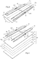
- photovoltaic modules 10 mounted on a supporting structure 30 of the supporting structure type in the open field.
- the structure 30 is adapted to receive the modules 10 with an inclination of each module of angle ⁇ with respect to the horizontal, provided to maximize the solar radiation incident on the module.
- connection and electrical current routing elements have been omitted for better clarity of the drawing.
- the structure 30 is a stainless steel structure comprising a plurality of beams 31, 33, 35 arranged between them so as to form a triangulated frame, on which are fixed cross members 37.
- each photovoltaic module 10 being mounted on the structure 30 by means of a fixing device 1 according to the invention.
- each module 10 is provided on its rear face 10A with two reinforcing profiles 20 and the fixing device 1 comprises, for each module 10, four supports 40 integral with the structure.
- each module 10 of this embodiment is a photovoltaic module without a frame, which comprises a front substrate 11, a rear substrate 12 and one or more photovoltaic cells 13 interposed between the front 11 and rear 12 substrates.
- the front substrate 11, intended to be arranged on the side of incidence of solar radiation on the module 10, is transparent, for example made of an extra-clear transparent glass or of a transparent thermoplastic polymer such as polycarbonate, polyurethane or polymethyl methacrylate.
- the rear substrate 12, intended to be arranged facing the structure 30, is made of any suitable material, transparent or not, in particular of glass.
- the or each photovoltaic cell 13 positioned between the substrates 11 and 12 is formed by a stack of thin layers comprising successively, from the front substrate 11, an electrically conductive transparent layer 14, in particular based on transparent conductive oxide (Transparent Conductive Oxide or TCO), which forms a front electrode of the cell; an absorber layer 15, suitable for converting the energy resulting from the solar radiation incident on the cell into electrical energy, in particular a thin layer based on silicon, amorphous or microcrystalline, or based on cadmium telluride; and an electrically conductive layer 16 which forms a rear electrode of the cell.
- TCO Transparent Conductive Oxide
- the absorber layer 15 of the or each cell 13 can be a thin layer of chalcopyrite compound comprising copper, indium and selenium, called the CIS absorber layer, optionally added with gallium (layer of CIGS absorber), aluminum or sulfur.
- the or each thin-film cell 13 comprises a stack similar to that described above, a polymer lamination spacer not shown being further positioned between the front electrode 14 of the cell and the front substrate 11, in order to to guarantee good cohesion of the module 10 during its assembly.
- the lamination interlayer can in particular consist of polyvinyl butyral (PVB) or ethylene vinyl acetate (EVA).
- the or each cell 13 can be formed from “wafers” or wafers of polycrystalline or monocrystalline silicon forming a p / n junction.
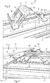
- each module 10 comprises two reinforcing profiles 20 integral with its rear face 10A intended to be opposite the structure 30, which is the face of the rear substrate 12 opposite to the or each photovoltaic cell 13.
- Each reinforcing profile 20 is of elongated shape with a longitudinal axis X 20 and is adapted to cooperate by snap-fastening with a support 40 at each of its ends 20A and 20B.
- the four supports 40 for receiving a module 10 are distributed in pairs on two adjacent crosspieces 37, so that in the snap-in configuration of the two profiles 20 of the module on the four corresponding supports 40, the longitudinal axis X 20 of each profile 20 is oriented transversely with respect to the X axis 37 of the cross members 37.
- each module 10 is arranged on the rear face 10A of the module with their longitudinal axes X 20 parallel to each other and to two opposite peripheral edges 18 of the module, so that, when the module 10 is mounted on the structure 30, the profiles 20 extend perpendicularly to the crosspieces 37.
- each section 20 is internally offset with respect to the corresponding lateral edge 18 of the module 10, so as to reinforce the structure of the module and to improve its mechanical strength.
- each reinforcing profile 20 of a module 10 is made of stainless steel and formed from a single blank cut and folded.
- Each section 20 has a cross section generally in the form of two omega nested one in the other. More precisely, each omega 21-25 or 23-27 comprises two branches, 21, 25 or 23, 27, which frame a central part 22-24 or 24-26 of the omega.
- Each central part 22-24 or 24-26 has a bottom wall and two side walls oblique with respect to the bottom wall, the two omegas being nested so that the bottom 23 or 25 of the central part of an omega forms a branch of the other omega.
- the walls 21, 23, 25 and 27 of the profile 20, which form the bottoms and the branches of the omegas, are substantially flat and intended to come opposite, respectively, the rear face 10A of the module 10, for the walls 23 and 27 , and of the structure 30, for the walls 21 and 25.
- the two reinforcing profiles 20 of each module 10 are secured directly to the rear face 10A of the module by gluing the walls 23 and 27 against the face 10A, by means of an adhesive material.
- the walls 21 and 22 of each section 20 define a notch 20C at a middle portion of the profile with respect to its longitudinal direction. This notch 20C is obtained by cutting the blank constituting the profile 20, before folding this blank.
- the notch 20C of each section 20 creates a material recess allowing the establishment of a connection box 50 on the rear face 10A of the module.
- Each module is thus equipped with two connection boxes 50, each housed at the level of the notch 20C of a section 20.
- the connection boxes 50 of a module 10 are connected to each other and to the outside by means of cables. 52, which allows the electrical connection of the module 10, once mounted on the structure 30, with adjacent modules 10 and devices, not shown, for making electrical current available.
- the two reinforcing profiles 20 of a module 10 are identical to each other and arranged on the rear face 10A of the module symmetrically to each other with respect to a central axis. X 10 of the module.
- the profiles 20 may be made of any material other than steel and suitable for their function, in particular of another metallic material or of a synthetic material, the profile being in the latter case obtained by extrusion of the synthetic material.
- Each support 40 of the fixing device 1 is fixed to the corresponding cross member 37 by means of two screws 39.
- Each support 40 is made of stainless steel and formed from a single folded and cut blank.
- the supports 40 are identical to each other and each have a cross section generally in the shape of an omega, comprising two branches 41 and 45 which frame a central part 42-44 of the omega.
- the central part of the omega has a bottom wall 43 and two side walls 42 and 44 oblique with respect to the bottom wall 43.
- this central part 42-44 of each support 40 is provided with a cross section U-shaped substantially complementary to the U-shaped cross section of part 22-24 of each section 20.
- part 22-24 of each section 20 of the module is capable of simultaneously covering the central part 42-44 with two supports 40 arranged on two adjacent sleepers 37, as shown on the figure 7 .
- the bottom wall 43 of each support 40 is equipped with resilient stops 47, intended to receive the wall 23 of a section 20 covering the support in abutment.
- At least one of the four supports 40 associated with the module is provided with an alignment pin 451 , at its wall 45.
- This pin 451 is intended to cooperate with a complementary orifice 251 provided in the wall 25 of at least one reinforcing profile 20 of the module, in the vicinity of the end 20A or 20B of the profile.
- the cooperation between the alignment pin 451 and the corresponding hole 251, combined with the relative engagement of the U-shaped parts 22-24 of the profiles and 42-44 of the supports, allows reliable indexing of the position of the module on the structure prior to their relative immobilization, which helps to facilitate assembly of the module on the structure.
- the side wall 42 of each support 40 comprises a tongue 48 provided to cooperate by snap-fastening with a notch 28 made in the side wall 22 of each reinforcing profile 20. More precisely, as shown. on the figure 2 , the side wall 22 of each section 20 comprises two notches 28, each arranged in the vicinity of one end 20A, 20B of the section.
- the tongue 48 of each of the two supports 40 is able to snap into the 'one of the two notches 28 of the profile.
- each module 10 on the structure 30 involves the latching of the tabs 48 of four supports 40 in four notches 28, distributed in pairs on the two reinforcing profiles 20 of the module.
- the two reinforcing profiles 20 of the module 10 are immobilized with respect to the four supports 40, so that the module 10 is fixed with respect to to structure 30.
- the side wall 42 of each support 40 also comprises, on either side of the tongue 48, two elastic blades 46 cut from the steel structure of the support 40. Two elastic blades 46 are also cut from the side wall 44 of each. support 40, symmetrically with respect to a median plane of the support.
- the four elastic blades 46 are suitable for exerting, on the walls 22 and 24 of a section 20 covering the support 40, a pushing force on the section 20 away from the support 40, and therefore from the module 10 away from the support. of structure 30, as shown by arrow P of figure 6 .
- the thrust force P exerted by the elastic blades 46 on the reinforcing profile 20 allows locking of the latching means 28 and 48 in their activated state, while maintaining the edge 281 of the notch 28 inside the groove 49.
- each reinforcing profile 20 of a module 10 also comprises two orifices 29, each located in the vicinity of one of the notches 28 so that, in the snap-in configuration of a tongue 48 relative to the notch 28, the orifice 29 is opposite the tongue 48. Thanks to this arrangement, it is possible to deactivate the latching means of a module 10 mounted on the structure 30, c ' that is, to unlock the assembly. As shown on the figure 7 , such unlocking is obtained by applying both a force F 2 pushing the module 10 towards the structure 30, against the elastic thrust P of the blades 46, and a force F 3 pushing each tongue 48 cooperating with a reinforcing profile of the module 10 away from the corresponding notch 28. The thrust force F 3 is exerted through the orifice 29 adjacent to the notch 28, using any suitable tool.
- a method of mounting photovoltaic modules 10 on the structure 30 by means of the fixing device 1 in accordance with the invention comprises steps as described below.
- the module 10 is fitted with its two reinforcing profiles 20, by gluing the walls 23 and 27 of the reinforcing profiles against the face 10A of the module, according to the arrangement shown in FIG. figure 3 .
- Supports 40 are also secured to the structure 30, by screwing by means of screws 39, by arranging the supports 40 on the cross members 37 of the structure with an appropriate spacing, corresponding to the spacing between the notches 28 of the reinforcing profiles 20 .
- each module 10 on the structure 30 then takes place as follows.
- the latching means 28 and 48 are mutually aligned.
- the central U-shaped portion 42-44 of two supports 40 arranged on two adjacent crossbars 37 is engaged inside the U-shaped portion 22-24 corresponding to each of the two reinforcing profiles 20 of the module 10.
- the alignment pin 451, provided on at least one of the four supports 40 associated with the module 10 is also introduced into the The corresponding orifice 251 of at least one reinforcing profile 20 of the module 10.
- the tabs 48 and notches 28 forming latching means are aligned two by two.
- a unidirectional force F 1 is then applied to push the module 10 towards the structure 30, so as to activate the latching means, that is to say to latch the tongue 48 of each of the four supports 40 associated with the module in the notch 28 which is aligned with the tab.
- the step of securing the reinforcing profiles 20 with the modules 10 can be carried out on the manufacturing site of the modules 10, while the following steps are carried out on the assembly site of the modules 10.
- the disassembly of the module 10 is carried out in a particularly simple manner, by simultaneously applying a force F 2 by pushing module 10 in the direction of the structure 30, against the elastic thrust P of the blades 46, and a thrust force F 3 of each tongue 48 cooperating with a reinforcing profile of the module 10 away from the corresponding notch 28, through the orifice 29 adjacent to the notch 28.
- the fixing device allows rapid and easy mounting of solar modules on a structure, such as a supporting structure in the open field, by the application of a force F 1 unidirectional thrust on each module previously positioned on the structure, without requiring special tools.
- This thrust force activates the snap-fastening of the module's reinforcing profiles with respect to supports integral with the structure.
- the positioning of the module on the structure for the prior alignment of the snap-fit means of the supports relative to the reinforcing profiles is also easy, in particular thanks to the complementary shape of certain parts 22-24 and 42-44 of the reinforcing profiles. 20 and supports 40.
- the fixing obtained of the modules on the structure is reliable and robust.
- the constituent elements of the fixing device according to the invention namely the reinforcing profiles 20 and the supports 40, have the advantage of being able to be manufactured in a simple and economical manner, by folding and cutting steel blanks. , so as to define the latching and locking means.
- the assembly of the modules with the structure obtained according to the invention is reversible, thanks to the presence of the unlocking holes 29, which allow individual dismantling of a module relative to the structure, in the event of failure of this module.
- the arrangement according to the invention can bring into play latching members other than tabs and notches, or even a number of notches and tabs different from what has been described above.
- the number and shape of the reinforcement profiles 20 associated with each module can also be different from those described above, the reinforcement profiles being advantageously distributed regularly on the face 10A of the module so as to reinforce the structure of the module.
- the arrangement according to the invention can be implemented for mounting on a structure of modules equipped or not with peripheral frames, the frameless option being however preferred.
- the arrangement according to the invention can also be used for mounting solar modules of any type, on a receiving structure also of any type.
- the photovoltaic solar modules described above can be replaced by thermal or mixed photovoltaic / thermal solar modules, and the receiving structure can equally well be a supporting structure in the open field, a roof or a facade.
Landscapes
- Engineering & Computer Science (AREA)
- Architecture (AREA)
- Civil Engineering (AREA)
- Structural Engineering (AREA)
- Physics & Mathematics (AREA)
- Thermal Sciences (AREA)
- Mechanical Engineering (AREA)
- General Engineering & Computer Science (AREA)
- Combustion & Propulsion (AREA)
- Chemical & Material Sciences (AREA)
- Sustainable Energy (AREA)
- Sustainable Development (AREA)
- Life Sciences & Earth Sciences (AREA)
- Power Engineering (AREA)
- Microelectronics & Electronic Packaging (AREA)
- Manufacturing & Machinery (AREA)
- Computer Hardware Design (AREA)
- General Physics & Mathematics (AREA)
- Condensed Matter Physics & Semiconductors (AREA)
- Electromagnetism (AREA)
- Roof Covering Using Slabs Or Stiff Sheets (AREA)
- Photovoltaic Devices (AREA)
Applications Claiming Priority (2)
| Application Number | Priority Date | Filing Date | Title |
|---|---|---|---|
| FR0953119A FR2945609B1 (fr) | 2009-05-12 | 2009-05-12 | Dispositif de fixation et procede de montage de modules solaires. |
| PCT/FR2010/050922 WO2010130952A2 (fr) | 2009-05-12 | 2010-05-12 | Dispositif de fixation et procede de montage de modules solaires |
Publications (2)
| Publication Number | Publication Date |
|---|---|
| EP2430378A2 EP2430378A2 (fr) | 2012-03-21 |
| EP2430378B1 true EP2430378B1 (fr) | 2021-10-27 |
Family
ID=41426927
Family Applications (1)
| Application Number | Title | Priority Date | Filing Date |
|---|---|---|---|
| EP10728747.6A Active EP2430378B1 (fr) | 2009-05-12 | 2010-05-12 | Arrangement comprenant un dispositif de fixation et procede de montage de cet arrangement |
Country Status (8)
| Country | Link |
|---|---|
| US (1) | US8763346B2 (zh) |
| EP (1) | EP2430378B1 (zh) |
| JP (1) | JP5934091B2 (zh) |
| KR (1) | KR101768728B1 (zh) |
| CN (1) | CN102597655B (zh) |
| ES (1) | ES2904687T3 (zh) |
| FR (1) | FR2945609B1 (zh) |
| WO (1) | WO2010130952A2 (zh) |
Families Citing this family (27)
| Publication number | Priority date | Publication date | Assignee | Title |
|---|---|---|---|---|
| DE202010005576U1 (de) * | 2010-06-07 | 2010-09-02 | SCHÜCO International KG | Wandkonstruktion |
| US20120145848A1 (en) * | 2010-12-10 | 2012-06-14 | David Schuff | Pier cap cleat |
| WO2012115544A1 (en) * | 2011-02-21 | 2012-08-30 | Sapa Profiler Ab | Construction frame and method for mounting of solar modules to a sub-structure |
| US20140196767A1 (en) * | 2011-06-02 | 2014-07-17 | Dow Corning Corporation | Photovoltaic Module Assembly And Method Of Assembling The Same |
| JP6470972B2 (ja) * | 2012-02-24 | 2019-02-13 | ソルベイ スペシャルティ ポリマーズ ユーエスエー, エルエルシー | ソーラーパネルのための骨組構造物 |
| EP2826075A4 (en) * | 2012-03-15 | 2015-06-17 | Magna Int Inc | MOUNTING STRUCTURE FOR SOLAR ENERGY PANELS |
| CN102709353A (zh) * | 2012-05-16 | 2012-10-03 | 李莉 | 一种太阳能电池板支架 |
| US9316417B2 (en) * | 2012-06-29 | 2016-04-19 | Sunpower Corporation | Framing system for mounting solar collecting devices |
| US8936164B2 (en) | 2012-07-06 | 2015-01-20 | Industrial Origami, Inc. | Solar panel rack |
| US10135386B2 (en) | 2012-10-12 | 2018-11-20 | Smash Solar, Inc. | Sensing, interlocking solar module system and installation method |
| JP2014196612A (ja) * | 2013-03-29 | 2014-10-16 | ホリー株式会社 | ソーラーパネル用架台及びその施工方法 |
| JP2014196613A (ja) * | 2013-03-29 | 2014-10-16 | ホリー株式会社 | ソーラーパネル用架台及びその施工方法 |
| FR3005951B1 (fr) * | 2013-05-24 | 2015-05-01 | Saint Gobain Isover | Dispositif pour la fabrication d'un produit fibreux |
| US9166526B2 (en) * | 2013-07-03 | 2015-10-20 | Industrial Origami, Inc. | Solar panel rack |
| US10171027B2 (en) * | 2015-03-02 | 2019-01-01 | Sunpower Corporation | Photovoltaic module mount |
| WO2017027758A2 (en) * | 2015-08-11 | 2017-02-16 | Smash Solar, Inc. | Interlocking, preassembled solar panel module system and installation method |
| EP3182580A1 (en) * | 2015-12-15 | 2017-06-21 | ML SYSTEM Spólka Akcyjna | A photovoltaic module for ventilated facade and a set of inner components of the facade fixing it to face walls of a building and joining the module with the inner structure of the facade |
| CN105834188B (zh) * | 2016-05-13 | 2017-03-22 | 北京中电博顺智能设备技术有限公司 | 一种光伏板清洗设备 |
| US9923513B2 (en) * | 2016-05-13 | 2018-03-20 | Boson Robotics Ltd. | Cleaning mechanism having water spray function and photovoltaic panel cleaning equipment having same |
| JP6542161B2 (ja) * | 2016-06-28 | 2019-07-10 | 株式会社サンレール | 太陽光発電パネル架台 |
| JP6592407B2 (ja) * | 2016-06-28 | 2019-10-16 | 株式会社サンレール | 太陽光発電パネル架台 |
| US11139776B2 (en) | 2016-07-01 | 2021-10-05 | Sunpower Corporation | Photovoltaic panel having a distributed support frame |
| US10490682B2 (en) | 2018-03-14 | 2019-11-26 | National Mechanical Group Corp. | Frame-less encapsulated photo-voltaic solar panel supporting solar cell modules encapsulated within multiple layers of optically-transparent epoxy-resin materials |
| US10602841B2 (en) * | 2018-04-05 | 2020-03-31 | Todd Hawkinson | Video screen holding assembly |
| TWM569526U (zh) * | 2018-07-03 | 2018-11-01 | 景欣有限公司 | 型鋼支撐件 |
| US11725876B2 (en) * | 2019-08-21 | 2023-08-15 | Rasp, Llc | Modular, portable cold room storage system |
| US11938576B1 (en) | 2022-12-20 | 2024-03-26 | Terabase Energy, Inc. | Systems and methods for threading a torque tube through U-bolt and module rail devices |
Family Cites Families (24)
| Publication number | Priority date | Publication date | Assignee | Title |
|---|---|---|---|---|
| US4254813A (en) * | 1979-06-20 | 1981-03-10 | Hunter Douglas International N.V. | Valance bracket for vertical venetian blind |
| JPS61130409U (zh) * | 1985-02-04 | 1986-08-15 | ||
| JPS6219326U (zh) * | 1985-07-19 | 1987-02-05 | ||
| US4677248A (en) * | 1985-09-13 | 1987-06-30 | Lacey Thomas G | Apparatus for mounting solar cells |
| JPH04269261A (ja) * | 1991-02-25 | 1992-09-25 | Inax Corp | 紙貼りタイルユニットの製造に用いる目地板の固定方法 |
| US5876084A (en) * | 1997-07-15 | 1999-03-02 | Prince Corporation | Panel mounting clip |
| AUPP558698A0 (en) * | 1998-08-31 | 1998-09-24 | Pacific Solar Pty Limited | Frame for mounting a panel or the like to a roof |
| IT1310335B1 (it) * | 1999-02-17 | 2002-02-13 | Technogym Srl | Macchina ginnica migliorata per l'esercizio degli arti inferiori. |
| DE19934073B4 (de) * | 1999-07-19 | 2005-08-25 | Regen Energiesysteme Gmbh | Vorrichtung zur Befestigung von Solarmodulen |
| JP3529312B2 (ja) * | 1999-12-24 | 2004-05-24 | ニチハ株式会社 | 建築板の留め付け構造 |
| US6360491B1 (en) * | 2000-01-14 | 2002-03-26 | Stanley A. Ullman | Roof support system for a solar panel |
| US6672018B2 (en) * | 2001-10-12 | 2004-01-06 | Jefferson Shingleton | Solar module mounting method and clip |
| RU2006118325A (ru) * | 2003-10-27 | 2007-12-10 | Астеллас Фарма Инк. (Jp) | Производные пиразина и их фармацевтическое применение |
| US7420177B2 (en) * | 2006-01-20 | 2008-09-02 | Evans & Sutherland Computer Corporation | High-resolution-imaging system for scanned-column projectors |
| DE202006018426U1 (de) * | 2006-12-04 | 2007-02-08 | Ideematec Deutschland Gmbh | Montageschienensystem |
| DE202007003060U1 (de) * | 2007-03-02 | 2008-07-17 | SCHÜCO International KG | Verbindungselement |
| FR2915217B1 (fr) * | 2007-04-20 | 2009-07-10 | Imphy Alloys Sa | Structure pour le montage dans une paroi d'un batiment de batis destines a supporter des panneaux tels que des panneaux photovoltaiques |
| DE102007027997B4 (de) * | 2007-06-14 | 2012-12-06 | Fath Gmbh Kunststoff- Und Stahltechnik | Befestigungseinrichtung für an einem Gestellaufbau anzuordnende flächige rahmenlose Bauteile, insbesondere Solarmodule |
| US8250829B2 (en) * | 2008-05-22 | 2012-08-28 | Mainstream Energy Corporation | Module attachment apparatus |
| DE102008027857A1 (de) | 2008-06-11 | 2009-03-05 | Leichtmetallbau Schletter Gmbh | Montagesystem für PV-Module |
| FR2939162A1 (fr) * | 2008-12-01 | 2010-06-04 | Saint Gobain | Toiture solaire |
| US8240109B2 (en) * | 2009-03-20 | 2012-08-14 | Northern States Metals Company | Support system for solar panels |
| US8191320B2 (en) * | 2009-10-15 | 2012-06-05 | Sunlink Corporation | Photovoltaic panel clamp |
| US8418983B2 (en) * | 2010-07-29 | 2013-04-16 | First Solar, Inc. | Slider clip and photovoltaic structure mounting system |
-
2009
- 2009-05-12 FR FR0953119A patent/FR2945609B1/fr active Active
-
2010
- 2010-05-12 CN CN201080032195.8A patent/CN102597655B/zh active Active
- 2010-05-12 KR KR1020117029476A patent/KR101768728B1/ko active IP Right Grant
- 2010-05-12 ES ES10728747T patent/ES2904687T3/es active Active
- 2010-05-12 US US13/319,894 patent/US8763346B2/en active Active
- 2010-05-12 JP JP2012510346A patent/JP5934091B2/ja active Active
- 2010-05-12 WO PCT/FR2010/050922 patent/WO2010130952A2/fr active Application Filing
- 2010-05-12 EP EP10728747.6A patent/EP2430378B1/fr active Active
Non-Patent Citations (1)
| Title |
|---|
| None * |
Also Published As
| Publication number | Publication date |
|---|---|
| KR101768728B1 (ko) | 2017-08-16 |
| FR2945609A1 (fr) | 2010-11-19 |
| WO2010130952A2 (fr) | 2010-11-18 |
| JP2012526933A (ja) | 2012-11-01 |
| US20120085395A1 (en) | 2012-04-12 |
| US8763346B2 (en) | 2014-07-01 |
| KR20120030085A (ko) | 2012-03-27 |
| ES2904687T3 (es) | 2022-04-05 |
| CN102597655B (zh) | 2015-10-14 |
| WO2010130952A3 (fr) | 2011-12-29 |
| EP2430378A2 (fr) | 2012-03-21 |
| JP5934091B2 (ja) | 2016-06-15 |
| CN102597655A (zh) | 2012-07-18 |
| FR2945609B1 (fr) | 2013-03-29 |
Similar Documents
| Publication | Publication Date | Title |
|---|---|---|
| EP2430378B1 (fr) | Arrangement comprenant un dispositif de fixation et procede de montage de cet arrangement | |
| FR2949494A1 (fr) | Dispositif de fixation et procede de montage de modules solaires | |
| EP2212919B1 (fr) | Perfectionnements apportés à des éléments capables de collecter de la lumière | |
| EP2452369B1 (fr) | Procédé de fabrication de cellules photovoltaiques multi-jonctions et multi-électrodes | |
| FR2651924A1 (fr) | Panneau solaire et procede pour assembler un tel panneau avec ses cellules et elements d'interconnexion. | |
| EP2488802A2 (fr) | Dispositif conformé pour fixer à lui seul un panneau solaire à une seule poutre d'une structure porteuse et installation comprenant un tel dispositif | |
| WO2011006957A2 (fr) | Plaque transparente texturee et procede de fabrication d'une telle plaque | |
| WO2015107293A1 (fr) | Centrale photovoltaïque mettant en œuvre des panneaux photovoltaïques supportés par des moyens flottants mettant en œuvre un ensemble de câbles | |
| EP3340318A1 (fr) | Dispositif photovoltaïque et procede de fabrication associe | |
| FR2952755A1 (fr) | Ensemble photovoltaique | |
| FR2997171A1 (fr) | Dispositif de fixation de tuiles solaires pour une toiture solaire | |
| US10707364B2 (en) | Solar cell with absorber substrate bonded between substrates | |
| WO2020229755A1 (fr) | Panneau photovoltaique | |
| WO2020229756A2 (fr) | Element de montage de panneau photovoltaique en toiture | |
| WO2013004923A1 (fr) | Procédé de réalisation d'une cellule photovoltaïque à homojonction comprenant un film mince de passivation en oxyde cristallin de silicium. | |
| WO2017081400A1 (fr) | Structure électronique sur support en céramique | |
| Schropp et al. | Technology of Solar Cells |
Legal Events
| Date | Code | Title | Description |
|---|---|---|---|
| PUAI | Public reference made under article 153(3) epc to a published international application that has entered the european phase |
Free format text: ORIGINAL CODE: 0009012 |
|
| AK | Designated contracting states |
Kind code of ref document: A2 Designated state(s): AL AT BE BG CH CY CZ DE DK EE ES FI FR GB GR HR HU IE IS IT LI LT LU LV MC MK MT NL NO PL PT RO SE SI SK SM TR |
|
| AX | Request for extension of the european patent |
Extension state: BA ME RS |
|
| 17P | Request for examination filed |
Effective date: 20120629 |
|
| RBV | Designated contracting states (corrected) |
Designated state(s): AL AT BE BG CH CY CZ DE DK EE ES FI FR GB GR HR HU IE IS IT LI LT LU LV MC MK MT NL NO PL PT RO SE SI SK SM TR |
|
| DAX | Request for extension of the european patent (deleted) | ||
| 17Q | First examination report despatched |
Effective date: 20160518 |
|
| STAA | Information on the status of an ep patent application or granted ep patent |
Free format text: STATUS: EXAMINATION IS IN PROGRESS |
|
| RAP1 | Party data changed (applicant data changed or rights of an application transferred) |
Owner name: (CNBM) BENGBU DESIGN & RESEARCH INSTITUTE FOR GLAS |
|
| REG | Reference to a national code |
Ref country code: DE Ref legal event code: R079 Ref document number: 602010067727 Country of ref document: DE Free format text: PREVIOUS MAIN CLASS: F24J0002520000 Ipc: H02S0020230000 |
|
| GRAP | Despatch of communication of intention to grant a patent |
Free format text: ORIGINAL CODE: EPIDOSNIGR1 |
|
| STAA | Information on the status of an ep patent application or granted ep patent |
Free format text: STATUS: GRANT OF PATENT IS INTENDED |
|
| RIC1 | Information provided on ipc code assigned before grant |
Ipc: H02S 20/23 20140101AFI20201102BHEP Ipc: F24S 25/12 20180101ALI20201102BHEP Ipc: H01L 31/18 20060101ALI20201102BHEP Ipc: F24S 25/00 20180101ALI20201102BHEP Ipc: F24S 25/632 20180101ALI20201102BHEP Ipc: F24S 25/65 20180101ALI20201102BHEP Ipc: H02S 20/10 20140101ALI20201102BHEP Ipc: H02S 20/26 20140101ALI20201102BHEP Ipc: F24S 25/60 20180101ALI20201102BHEP |
|
| INTG | Intention to grant announced |
Effective date: 20201204 |
|
| GRAS | Grant fee paid |
Free format text: ORIGINAL CODE: EPIDOSNIGR3 |
|
| GRAA | (expected) grant |
Free format text: ORIGINAL CODE: 0009210 |
|
| STAA | Information on the status of an ep patent application or granted ep patent |
Free format text: STATUS: THE PATENT HAS BEEN GRANTED |
|
| AK | Designated contracting states |
Kind code of ref document: B1 Designated state(s): AL AT BE BG CH CY CZ DE DK EE ES FI FR GB GR HR HU IE IS IT LI LT LU LV MC MK MT NL NO PL PT RO SE SI SK SM TR |
|
| REG | Reference to a national code |
Ref country code: GB Ref legal event code: FG4D Free format text: NOT ENGLISH |
|
| REG | Reference to a national code |
Ref country code: CH Ref legal event code: EP |
|
| REG | Reference to a national code |
Ref country code: AT Ref legal event code: REF Ref document number: 1442756 Country of ref document: AT Kind code of ref document: T Effective date: 20211115 |
|
| REG | Reference to a national code |
Ref country code: DE Ref legal event code: R096 Ref document number: 602010067727 Country of ref document: DE |
|
| REG | Reference to a national code |
Ref country code: IE Ref legal event code: FG4D Free format text: LANGUAGE OF EP DOCUMENT: FRENCH |
|
| REG | Reference to a national code |
Ref country code: LT Ref legal event code: MG9D |
|
| REG | Reference to a national code |
Ref country code: NL Ref legal event code: MP Effective date: 20211027 |
|
| REG | Reference to a national code |
Ref country code: AT Ref legal event code: MK05 Ref document number: 1442756 Country of ref document: AT Kind code of ref document: T Effective date: 20211027 |
|
| REG | Reference to a national code |
Ref country code: ES Ref legal event code: FG2A Ref document number: 2904687 Country of ref document: ES Kind code of ref document: T3 Effective date: 20220405 |
|
| PG25 | Lapsed in a contracting state [announced via postgrant information from national office to epo] |
Ref country code: LT Free format text: LAPSE BECAUSE OF FAILURE TO SUBMIT A TRANSLATION OF THE DESCRIPTION OR TO PAY THE FEE WITHIN THE PRESCRIBED TIME-LIMIT Effective date: 20211027 Ref country code: FI Free format text: LAPSE BECAUSE OF FAILURE TO SUBMIT A TRANSLATION OF THE DESCRIPTION OR TO PAY THE FEE WITHIN THE PRESCRIBED TIME-LIMIT Effective date: 20211027 Ref country code: BG Free format text: LAPSE BECAUSE OF FAILURE TO SUBMIT A TRANSLATION OF THE DESCRIPTION OR TO PAY THE FEE WITHIN THE PRESCRIBED TIME-LIMIT Effective date: 20220127 Ref country code: AT Free format text: LAPSE BECAUSE OF FAILURE TO SUBMIT A TRANSLATION OF THE DESCRIPTION OR TO PAY THE FEE WITHIN THE PRESCRIBED TIME-LIMIT Effective date: 20211027 |
|
| PG25 | Lapsed in a contracting state [announced via postgrant information from national office to epo] |
Ref country code: IS Free format text: LAPSE BECAUSE OF FAILURE TO SUBMIT A TRANSLATION OF THE DESCRIPTION OR TO PAY THE FEE WITHIN THE PRESCRIBED TIME-LIMIT Effective date: 20220227 Ref country code: SE Free format text: LAPSE BECAUSE OF FAILURE TO SUBMIT A TRANSLATION OF THE DESCRIPTION OR TO PAY THE FEE WITHIN THE PRESCRIBED TIME-LIMIT Effective date: 20211027 Ref country code: PT Free format text: LAPSE BECAUSE OF FAILURE TO SUBMIT A TRANSLATION OF THE DESCRIPTION OR TO PAY THE FEE WITHIN THE PRESCRIBED TIME-LIMIT Effective date: 20220228 Ref country code: PL Free format text: LAPSE BECAUSE OF FAILURE TO SUBMIT A TRANSLATION OF THE DESCRIPTION OR TO PAY THE FEE WITHIN THE PRESCRIBED TIME-LIMIT Effective date: 20211027 Ref country code: NO Free format text: LAPSE BECAUSE OF FAILURE TO SUBMIT A TRANSLATION OF THE DESCRIPTION OR TO PAY THE FEE WITHIN THE PRESCRIBED TIME-LIMIT Effective date: 20220127 Ref country code: NL Free format text: LAPSE BECAUSE OF FAILURE TO SUBMIT A TRANSLATION OF THE DESCRIPTION OR TO PAY THE FEE WITHIN THE PRESCRIBED TIME-LIMIT Effective date: 20211027 Ref country code: LV Free format text: LAPSE BECAUSE OF FAILURE TO SUBMIT A TRANSLATION OF THE DESCRIPTION OR TO PAY THE FEE WITHIN THE PRESCRIBED TIME-LIMIT Effective date: 20211027 Ref country code: HR Free format text: LAPSE BECAUSE OF FAILURE TO SUBMIT A TRANSLATION OF THE DESCRIPTION OR TO PAY THE FEE WITHIN THE PRESCRIBED TIME-LIMIT Effective date: 20211027 Ref country code: GR Free format text: LAPSE BECAUSE OF FAILURE TO SUBMIT A TRANSLATION OF THE DESCRIPTION OR TO PAY THE FEE WITHIN THE PRESCRIBED TIME-LIMIT Effective date: 20220128 |
|
| REG | Reference to a national code |
Ref country code: DE Ref legal event code: R097 Ref document number: 602010067727 Country of ref document: DE |
|
| PG25 | Lapsed in a contracting state [announced via postgrant information from national office to epo] |
Ref country code: SM Free format text: LAPSE BECAUSE OF FAILURE TO SUBMIT A TRANSLATION OF THE DESCRIPTION OR TO PAY THE FEE WITHIN THE PRESCRIBED TIME-LIMIT Effective date: 20211027 Ref country code: SK Free format text: LAPSE BECAUSE OF FAILURE TO SUBMIT A TRANSLATION OF THE DESCRIPTION OR TO PAY THE FEE WITHIN THE PRESCRIBED TIME-LIMIT Effective date: 20211027 Ref country code: RO Free format text: LAPSE BECAUSE OF FAILURE TO SUBMIT A TRANSLATION OF THE DESCRIPTION OR TO PAY THE FEE WITHIN THE PRESCRIBED TIME-LIMIT Effective date: 20211027 Ref country code: EE Free format text: LAPSE BECAUSE OF FAILURE TO SUBMIT A TRANSLATION OF THE DESCRIPTION OR TO PAY THE FEE WITHIN THE PRESCRIBED TIME-LIMIT Effective date: 20211027 Ref country code: DK Free format text: LAPSE BECAUSE OF FAILURE TO SUBMIT A TRANSLATION OF THE DESCRIPTION OR TO PAY THE FEE WITHIN THE PRESCRIBED TIME-LIMIT Effective date: 20211027 Ref country code: CZ Free format text: LAPSE BECAUSE OF FAILURE TO SUBMIT A TRANSLATION OF THE DESCRIPTION OR TO PAY THE FEE WITHIN THE PRESCRIBED TIME-LIMIT Effective date: 20211027 |
|
| PLBE | No opposition filed within time limit |
Free format text: ORIGINAL CODE: 0009261 |
|
| STAA | Information on the status of an ep patent application or granted ep patent |
Free format text: STATUS: NO OPPOSITION FILED WITHIN TIME LIMIT |
|
| 26N | No opposition filed |
Effective date: 20220728 |
|
| PG25 | Lapsed in a contracting state [announced via postgrant information from national office to epo] |
Ref country code: AL Free format text: LAPSE BECAUSE OF FAILURE TO SUBMIT A TRANSLATION OF THE DESCRIPTION OR TO PAY THE FEE WITHIN THE PRESCRIBED TIME-LIMIT Effective date: 20211027 |
|
| PG25 | Lapsed in a contracting state [announced via postgrant information from national office to epo] |
Ref country code: SI Free format text: LAPSE BECAUSE OF FAILURE TO SUBMIT A TRANSLATION OF THE DESCRIPTION OR TO PAY THE FEE WITHIN THE PRESCRIBED TIME-LIMIT Effective date: 20211027 |
|
| REG | Reference to a national code |
Ref country code: CH Ref legal event code: PL |
|
| REG | Reference to a national code |
Ref country code: BE Ref legal event code: MM Effective date: 20220531 |
|
| PG25 | Lapsed in a contracting state [announced via postgrant information from national office to epo] |
Ref country code: MC Free format text: LAPSE BECAUSE OF FAILURE TO SUBMIT A TRANSLATION OF THE DESCRIPTION OR TO PAY THE FEE WITHIN THE PRESCRIBED TIME-LIMIT Effective date: 20211027 Ref country code: LU Free format text: LAPSE BECAUSE OF NON-PAYMENT OF DUE FEES Effective date: 20220512 Ref country code: LI Free format text: LAPSE BECAUSE OF NON-PAYMENT OF DUE FEES Effective date: 20220531 Ref country code: CH Free format text: LAPSE BECAUSE OF NON-PAYMENT OF DUE FEES Effective date: 20220531 |
|
| REG | Reference to a national code |
Ref country code: FR Ref legal event code: PLFP Year of fee payment: 14 |
|
| PG25 | Lapsed in a contracting state [announced via postgrant information from national office to epo] |
Ref country code: IE Free format text: LAPSE BECAUSE OF NON-PAYMENT OF DUE FEES Effective date: 20220512 |
|
| PG25 | Lapsed in a contracting state [announced via postgrant information from national office to epo] |
Ref country code: BE Free format text: LAPSE BECAUSE OF NON-PAYMENT OF DUE FEES Effective date: 20220531 |
|
| PGFP | Annual fee paid to national office [announced via postgrant information from national office to epo] |
Ref country code: IT Payment date: 20230413 Year of fee payment: 14 Ref country code: FR Payment date: 20230413 Year of fee payment: 14 Ref country code: ES Payment date: 20230607 Year of fee payment: 14 Ref country code: DE Payment date: 20230413 Year of fee payment: 14 |
|
| PGFP | Annual fee paid to national office [announced via postgrant information from national office to epo] |
Ref country code: GB Payment date: 20230413 Year of fee payment: 14 |
|
| PG25 | Lapsed in a contracting state [announced via postgrant information from national office to epo] |
Ref country code: HU Free format text: LAPSE BECAUSE OF FAILURE TO SUBMIT A TRANSLATION OF THE DESCRIPTION OR TO PAY THE FEE WITHIN THE PRESCRIBED TIME-LIMIT; INVALID AB INITIO Effective date: 20100512 |
|
| PG25 | Lapsed in a contracting state [announced via postgrant information from national office to epo] |
Ref country code: MK Free format text: LAPSE BECAUSE OF FAILURE TO SUBMIT A TRANSLATION OF THE DESCRIPTION OR TO PAY THE FEE WITHIN THE PRESCRIBED TIME-LIMIT Effective date: 20211027 Ref country code: CY Free format text: LAPSE BECAUSE OF FAILURE TO SUBMIT A TRANSLATION OF THE DESCRIPTION OR TO PAY THE FEE WITHIN THE PRESCRIBED TIME-LIMIT Effective date: 20211027 |
|
| PGFP | Annual fee paid to national office [announced via postgrant information from national office to epo] |
Ref country code: GB Payment date: 20240327 Year of fee payment: 15 |