EP2429328B1 - Verbindungselement zum bilden des steckabschnitts einer automatischen befestigungsvorrichtung - Google Patents
Verbindungselement zum bilden des steckabschnitts einer automatischen befestigungsvorrichtung Download PDFInfo
- Publication number
- EP2429328B1 EP2429328B1 EP10723168A EP10723168A EP2429328B1 EP 2429328 B1 EP2429328 B1 EP 2429328B1 EP 10723168 A EP10723168 A EP 10723168A EP 10723168 A EP10723168 A EP 10723168A EP 2429328 B1 EP2429328 B1 EP 2429328B1
- Authority
- EP
- European Patent Office
- Prior art keywords
- sheet
- head
- stem
- interstice
- support
- Prior art date
- Legal status (The legal status is an assumption and is not a legal conclusion. Google has not performed a legal analysis and makes no representation as to the accuracy of the status listed.)
- Active
Links
Images


Classifications
-
- A—HUMAN NECESSITIES
- A44—HABERDASHERY; JEWELLERY
- A44B—BUTTONS, PINS, BUCKLES, SLIDE FASTENERS, OR THE LIKE
- A44B18/00—Fasteners of the touch-and-close type; Making such fasteners
- A44B18/0046—Fasteners made integrally of plastics
- A44B18/0061—Male or hook elements
- A44B18/0065—Male or hook elements of a mushroom type
-
- B—PERFORMING OPERATIONS; TRANSPORTING
- B29—WORKING OF PLASTICS; WORKING OF SUBSTANCES IN A PLASTIC STATE IN GENERAL
- B29C—SHAPING OR JOINING OF PLASTICS; SHAPING OF MATERIAL IN A PLASTIC STATE, NOT OTHERWISE PROVIDED FOR; AFTER-TREATMENT OF THE SHAPED PRODUCTS, e.g. REPAIRING
- B29C43/00—Compression moulding, i.e. applying external pressure to flow the moulding material; Apparatus therefor
- B29C43/22—Compression moulding, i.e. applying external pressure to flow the moulding material; Apparatus therefor of articles of indefinite length
- B29C43/222—Compression moulding, i.e. applying external pressure to flow the moulding material; Apparatus therefor of articles of indefinite length characterised by the shape of the surface
-
- A—HUMAN NECESSITIES
- A44—HABERDASHERY; JEWELLERY
- A44B—BUTTONS, PINS, BUCKLES, SLIDE FASTENERS, OR THE LIKE
- A44B18/00—Fasteners of the touch-and-close type; Making such fasteners
-
- B—PERFORMING OPERATIONS; TRANSPORTING
- B65—CONVEYING; PACKING; STORING; HANDLING THIN OR FILAMENTARY MATERIAL
- B65H—HANDLING THIN OR FILAMENTARY MATERIAL, e.g. SHEETS, WEBS, CABLES
- B65H37/00—Article or web delivery apparatus incorporating devices for performing specified auxiliary operations
-
- B—PERFORMING OPERATIONS; TRANSPORTING
- B29—WORKING OF PLASTICS; WORKING OF SUBSTANCES IN A PLASTIC STATE IN GENERAL
- B29C—SHAPING OR JOINING OF PLASTICS; SHAPING OF MATERIAL IN A PLASTIC STATE, NOT OTHERWISE PROVIDED FOR; AFTER-TREATMENT OF THE SHAPED PRODUCTS, e.g. REPAIRING
- B29C43/00—Compression moulding, i.e. applying external pressure to flow the moulding material; Apparatus therefor
- B29C43/32—Component parts, details or accessories; Auxiliary operations
- B29C43/44—Compression means for making articles of indefinite length
- B29C43/46—Rollers
- B29C2043/461—Rollers the rollers having specific surface features
-
- B—PERFORMING OPERATIONS; TRANSPORTING
- B29—WORKING OF PLASTICS; WORKING OF SUBSTANCES IN A PLASTIC STATE IN GENERAL
- B29C—SHAPING OR JOINING OF PLASTICS; SHAPING OF MATERIAL IN A PLASTIC STATE, NOT OTHERWISE PROVIDED FOR; AFTER-TREATMENT OF THE SHAPED PRODUCTS, e.g. REPAIRING
- B29C43/00—Compression moulding, i.e. applying external pressure to flow the moulding material; Apparatus therefor
- B29C43/32—Component parts, details or accessories; Auxiliary operations
- B29C43/44—Compression means for making articles of indefinite length
- B29C43/48—Endless belts
- B29C2043/483—Endless belts cooperating with a second endless belt, i.e. double band presses
-
- B—PERFORMING OPERATIONS; TRANSPORTING
- B29—WORKING OF PLASTICS; WORKING OF SUBSTANCES IN A PLASTIC STATE IN GENERAL
- B29C—SHAPING OR JOINING OF PLASTICS; SHAPING OF MATERIAL IN A PLASTIC STATE, NOT OTHERWISE PROVIDED FOR; AFTER-TREATMENT OF THE SHAPED PRODUCTS, e.g. REPAIRING
- B29C43/00—Compression moulding, i.e. applying external pressure to flow the moulding material; Apparatus therefor
- B29C43/32—Component parts, details or accessories; Auxiliary operations
- B29C43/44—Compression means for making articles of indefinite length
- B29C43/48—Endless belts
- B29C2043/486—Endless belts cooperating with rollers or drums
-
- B—PERFORMING OPERATIONS; TRANSPORTING
- B29—WORKING OF PLASTICS; WORKING OF SUBSTANCES IN A PLASTIC STATE IN GENERAL
- B29C—SHAPING OR JOINING OF PLASTICS; SHAPING OF MATERIAL IN A PLASTIC STATE, NOT OTHERWISE PROVIDED FOR; AFTER-TREATMENT OF THE SHAPED PRODUCTS, e.g. REPAIRING
- B29C43/00—Compression moulding, i.e. applying external pressure to flow the moulding material; Apparatus therefor
- B29C43/32—Component parts, details or accessories; Auxiliary operations
- B29C43/44—Compression means for making articles of indefinite length
-
- B—PERFORMING OPERATIONS; TRANSPORTING
- B29—WORKING OF PLASTICS; WORKING OF SUBSTANCES IN A PLASTIC STATE IN GENERAL
- B29C—SHAPING OR JOINING OF PLASTICS; SHAPING OF MATERIAL IN A PLASTIC STATE, NOT OTHERWISE PROVIDED FOR; AFTER-TREATMENT OF THE SHAPED PRODUCTS, e.g. REPAIRING
- B29C43/00—Compression moulding, i.e. applying external pressure to flow the moulding material; Apparatus therefor
- B29C43/32—Component parts, details or accessories; Auxiliary operations
- B29C43/44—Compression means for making articles of indefinite length
- B29C43/46—Rollers
-
- B—PERFORMING OPERATIONS; TRANSPORTING
- B29—WORKING OF PLASTICS; WORKING OF SUBSTANCES IN A PLASTIC STATE IN GENERAL
- B29C—SHAPING OR JOINING OF PLASTICS; SHAPING OF MATERIAL IN A PLASTIC STATE, NOT OTHERWISE PROVIDED FOR; AFTER-TREATMENT OF THE SHAPED PRODUCTS, e.g. REPAIRING
- B29C43/00—Compression moulding, i.e. applying external pressure to flow the moulding material; Apparatus therefor
- B29C43/32—Component parts, details or accessories; Auxiliary operations
- B29C43/44—Compression means for making articles of indefinite length
- B29C43/48—Endless belts
-
- B—PERFORMING OPERATIONS; TRANSPORTING
- B29—WORKING OF PLASTICS; WORKING OF SUBSTANCES IN A PLASTIC STATE IN GENERAL
- B29C—SHAPING OR JOINING OF PLASTICS; SHAPING OF MATERIAL IN A PLASTIC STATE, NOT OTHERWISE PROVIDED FOR; AFTER-TREATMENT OF THE SHAPED PRODUCTS, e.g. REPAIRING
- B29C59/00—Surface shaping of articles, e.g. embossing; Apparatus therefor
- B29C59/02—Surface shaping of articles, e.g. embossing; Apparatus therefor by mechanical means, e.g. pressing
-
- B—PERFORMING OPERATIONS; TRANSPORTING
- B29—WORKING OF PLASTICS; WORKING OF SUBSTANCES IN A PLASTIC STATE IN GENERAL
- B29C—SHAPING OR JOINING OF PLASTICS; SHAPING OF MATERIAL IN A PLASTIC STATE, NOT OTHERWISE PROVIDED FOR; AFTER-TREATMENT OF THE SHAPED PRODUCTS, e.g. REPAIRING
- B29C67/00—Shaping techniques not covered by groups B29C39/00 - B29C65/00, B29C70/00 or B29C73/00
- B29C67/0003—Moulding articles between moving mould surfaces, e.g. turning surfaces
-
- B—PERFORMING OPERATIONS; TRANSPORTING
- B29—WORKING OF PLASTICS; WORKING OF SUBSTANCES IN A PLASTIC STATE IN GENERAL
- B29L—INDEXING SCHEME ASSOCIATED WITH SUBCLASS B29C, RELATING TO PARTICULAR ARTICLES
- B29L2007/00—Flat articles, e.g. films or sheets
- B29L2007/001—Flat articles, e.g. films or sheets having irregular or rough surfaces
-
- B—PERFORMING OPERATIONS; TRANSPORTING
- B29—WORKING OF PLASTICS; WORKING OF SUBSTANCES IN A PLASTIC STATE IN GENERAL
- B29L—INDEXING SCHEME ASSOCIATED WITH SUBCLASS B29C, RELATING TO PARTICULAR ARTICLES
- B29L2031/00—Other particular articles
- B29L2031/727—Fastening elements
- B29L2031/729—Hook and loop-type fasteners
-
- B—PERFORMING OPERATIONS; TRANSPORTING
- B65—CONVEYING; PACKING; STORING; HANDLING THIN OR FILAMENTARY MATERIAL
- B65H—HANDLING THIN OR FILAMENTARY MATERIAL, e.g. SHEETS, WEBS, CABLES
- B65H2301/00—Handling processes for sheets or webs
- B65H2301/50—Auxiliary process performed during handling process
- B65H2301/51—Modifying a characteristic of handled material
- B65H2301/511—Processing surface of handled material upon transport or guiding thereof, e.g. cleaning
-
- B—PERFORMING OPERATIONS; TRANSPORTING
- B65—CONVEYING; PACKING; STORING; HANDLING THIN OR FILAMENTARY MATERIAL
- B65H—HANDLING THIN OR FILAMENTARY MATERIAL, e.g. SHEETS, WEBS, CABLES
- B65H2301/00—Handling processes for sheets or webs
- B65H2301/50—Auxiliary process performed during handling process
- B65H2301/51—Modifying a characteristic of handled material
- B65H2301/512—Changing form of handled material
-
- Y—GENERAL TAGGING OF NEW TECHNOLOGICAL DEVELOPMENTS; GENERAL TAGGING OF CROSS-SECTIONAL TECHNOLOGIES SPANNING OVER SEVERAL SECTIONS OF THE IPC; TECHNICAL SUBJECTS COVERED BY FORMER USPC CROSS-REFERENCE ART COLLECTIONS [XRACs] AND DIGESTS
- Y10—TECHNICAL SUBJECTS COVERED BY FORMER USPC
- Y10T—TECHNICAL SUBJECTS COVERED BY FORMER US CLASSIFICATION
- Y10T24/00—Buckles, buttons, clasps, etc.
- Y10T24/27—Buckles, buttons, clasps, etc. including readily dissociable fastener having numerous, protruding, unitary filaments randomly interlocking with, and simultaneously moving towards, mating structure [e.g., hook-loop type fastener]
-
- Y—GENERAL TAGGING OF NEW TECHNOLOGICAL DEVELOPMENTS; GENERAL TAGGING OF CROSS-SECTIONAL TECHNOLOGIES SPANNING OVER SEVERAL SECTIONS OF THE IPC; TECHNICAL SUBJECTS COVERED BY FORMER USPC CROSS-REFERENCE ART COLLECTIONS [XRACs] AND DIGESTS
- Y10—TECHNICAL SUBJECTS COVERED BY FORMER USPC
- Y10T—TECHNICAL SUBJECTS COVERED BY FORMER US CLASSIFICATION
- Y10T24/00—Buckles, buttons, clasps, etc.
- Y10T24/27—Buckles, buttons, clasps, etc. including readily dissociable fastener having numerous, protruding, unitary filaments randomly interlocking with, and simultaneously moving towards, mating structure [e.g., hook-loop type fastener]
- Y10T24/2767—Buckles, buttons, clasps, etc. including readily dissociable fastener having numerous, protruding, unitary filaments randomly interlocking with, and simultaneously moving towards, mating structure [e.g., hook-loop type fastener] having several, repeating, interlocking formations along length of filaments
-
- Y—GENERAL TAGGING OF NEW TECHNOLOGICAL DEVELOPMENTS; GENERAL TAGGING OF CROSS-SECTIONAL TECHNOLOGIES SPANNING OVER SEVERAL SECTIONS OF THE IPC; TECHNICAL SUBJECTS COVERED BY FORMER USPC CROSS-REFERENCE ART COLLECTIONS [XRACs] AND DIGESTS
- Y10—TECHNICAL SUBJECTS COVERED BY FORMER USPC
- Y10T—TECHNICAL SUBJECTS COVERED BY FORMER US CLASSIFICATION
- Y10T24/00—Buckles, buttons, clasps, etc.
- Y10T24/27—Buckles, buttons, clasps, etc. including readily dissociable fastener having numerous, protruding, unitary filaments randomly interlocking with, and simultaneously moving towards, mating structure [e.g., hook-loop type fastener]
- Y10T24/2775—Buckles, buttons, clasps, etc. including readily dissociable fastener having numerous, protruding, unitary filaments randomly interlocking with, and simultaneously moving towards, mating structure [e.g., hook-loop type fastener] having opposed structure formed from distinct filaments of diverse shape to those mating therewith
-
- Y—GENERAL TAGGING OF NEW TECHNOLOGICAL DEVELOPMENTS; GENERAL TAGGING OF CROSS-SECTIONAL TECHNOLOGIES SPANNING OVER SEVERAL SECTIONS OF THE IPC; TECHNICAL SUBJECTS COVERED BY FORMER USPC CROSS-REFERENCE ART COLLECTIONS [XRACs] AND DIGESTS
- Y10—TECHNICAL SUBJECTS COVERED BY FORMER USPC
- Y10T—TECHNICAL SUBJECTS COVERED BY FORMER US CLASSIFICATION
- Y10T24/00—Buckles, buttons, clasps, etc.
- Y10T24/27—Buckles, buttons, clasps, etc. including readily dissociable fastener having numerous, protruding, unitary filaments randomly interlocking with, and simultaneously moving towards, mating structure [e.g., hook-loop type fastener]
- Y10T24/2792—Buckles, buttons, clasps, etc. including readily dissociable fastener having numerous, protruding, unitary filaments randomly interlocking with, and simultaneously moving towards, mating structure [e.g., hook-loop type fastener] having mounting surface and filaments constructed from common piece of material
Definitions
- the present invention relates to a ply with gripping elements intended to form the male part of a hook-and-loop type (hook-and-loop) self-gripping type, which consists of a ply, in particular a thermoplastic material, from which protruding fastening elements having a rod extending transversely, in particular substantially perpendicular to the ply and terminated by a head which projects laterally from the rod.
- a hook-and-loop type hook-and-loop self-gripping type
- the present invention also relates to a method of manufacturing a sheet of this kind and to an installation for manufacturing a sheet of this kind.
- mushroom-shaped hook plies that is to say consisting of a strip of thermoplastic material from which mushroom-shaped attachment elements each consisting of a rod substantially perpendicular to the web and a head portion which protrudes laterally from the rod all around thereof, extruding a thermoplastic material from an extruder to form and convey a web, substantially in a form which will later be called fondue and which, although not liquid, is not completely solid but is partly softened, between a pressing roll and a forming roll, the forming roll having cavities having the complementary form of rods, so that when the sheet is passed between the two rollers, is obtained at the outlet, after solidification of the material, a sheet having substantially cylindrical rods o u conical, which is then deformed by pressing and / or heating the upper part to form a head mushroom shaped hanging.
- hooking elements derived from the web are intended to cooperate with loops of a loop part constituted, for example, of a fabric (knitted or woven) with loops, in particular made on a three-bar loom comprising threads. warp, weft yarns and loop yarns, or a nonwoven forming loops.
- a hook tablecloth is known from
- fastening elements which, when they cooperate with loop parts, have the greatest tensile and / or peel strength possible.
- angle of articulation pronunciation of the curvature of the lower surface of the head in a half-plane of radial longitudinal section (with respect to the median longitudinal axis of the rod, in particular the vertical axis passing through by the center of the rod) given, or angle of attachment left, respectively straight, the angle ⁇ formed in the half plane of radial longitudinal section given between on the one hand the perpendicular axis (typically horizontal) to the longitudinal axis of the rod (conventionally the vertical) and the straight line passing through the two points Ph and Pb of the given radial plane defined as being respectively, for Pb, the point of the head furthest from the rod in this radial half-plane , and Ph, the first point of the lower surface of the head of the fastening element, starting from the stem and going towards the point Pb, where the tangent to this lower surface is the least inclined (in absolute value ) with respect to xe perpendicular (classically horizontal), in particular is parallel to this one
- the hooking angle When the line PhPb is inclined downwards with respect to the perpendicular axis (typically horizontal) to the longitudinal axis of the rod, the hooking angle is positive and when it is inclined upwards the angle is negative.
- a sheet having fastening elements comprising a base strip, in particular made of thermoplastic material, and at least one fastening element coming from the strip, the fastening element consisting of a part of rod and a head portion projecting laterally from the rod, the head having two left and right wings projecting laterally from the rod in a transverse direction, or CD, respectively having a latching angle the largest left and law ; and secondly, radially between the two wings, an advanced rear portion projecting from the rear side rod in a direction MD perpendicular to the direction CD having a rearmost engagement angle, is characterized in that that the two largest hooking angles left and right are greater than the largest rear hooking angle.
- the head has a shape which proves to lead to advantages in terms of cooperation of the fastening element with loops, those which can come along certain "axes of approach” easily hang, and then being better maintained by the larger parts.
- the largest left and right hooking angles are strictly positive while the rearmost hooking angle is zero or less than zero.
- the head on a front part, that is to say the opposite side to the forward portion does not project laterally from the rod.
- the head is also projecting from the rod, so that the head protrudes from the rod 360 °, and the attachment element is then a mushroom.
- the two left and right wings are substantially symmetrical with respect to the central longitudinal plane MD.
- the distance from which each wing projects from a left or right side in the transverse direction increases, as from the front side going in the direction towards the rear side and this up to an intermediate point farthest from the stem.
- the rod has a shape in polygonal cross section, in particular substantially rectangular or square, preferably having a ratio of the greatest dimension in length over the largest dimension in width which is between 1 and 2 strictly, the dimension in length extending from reference in the MD direction.
- the head comprises two rib-shaped protrusions which extend from the edges of the rod formed by its rear corners to the outer edge of the head, in particular to the points of the outer edge where the left and right wings meet each other and the rear part is advanced.
- each rib has a ridge in continuity with the respective edge of the stem from which it extends.
- the delimitation plane between the head and the shank is inclined downward in the rearward direction relative to the plane of the base.
- the upper surface of the head comprises a concave region whose concavity is turned in a direction away from the attachment element, this concave region being delimited at back by a ridge line and forward by the stem-head delineation plane.
- the ridge line has two right and left vertex points which are the two highest points of the head respectively to the right and to the left of the front to back axis of the head passing through the axis of the rod.
- the two vertex points are closer to the leading edge than the trailing edge.
- the present invention also relates to a method for manufacturing a sheet with fastening elements, in particular a sheet with fastening elements according to the invention.
- the support element is a roller and the pressing element has a circular cylindrical surface whose concavity is turned towards the supporting element, the arrangement of the two elements being such that the interstice formed between the two decreases from the entrance to the exit of the gap.
- one of the elements is maintained at ambient temperature, while the other element is heated, in particular at a softening temperature (that is to say beyond the limit of the elastic deformation) between 100 ° C and 165 ° C, especially when the thermoplastic material is a polyolefin, for example a PE (Polyethylene) or a PP (polypropylene) or a copolymer.
- a softening temperature that is to say beyond the limit of the elastic deformation
- the element maintained at ambient temperature is the support element, ie the element on the side of the web opposite the rods, while the heated element is the pressing element.
- the preform consists of a rod and a head projecting from the rod in the direction at the front of the web, and at the exit of the decreasing gap, after deformation of the head by the surface.
- fastening elements as in the invention having a portion advanced in the direction at the rear of the web, that is to say the opposite side with respect to the head of the preform and in particular the opposite side to the direction of travel of the product.
- the preform sheet conveyed in the gap is obtained by conveying a rod ply comprising a base strip and rods protruding transversely, in particular substantially perpendicularly, from the ply, in particular being of cylindrical shape, in particular of a polygonal shape, in particular square or rectangular and / or conical, between a prior support element, in particular a support roller beforehand, and a pre-pressing element, in particular a pre-pressing roll; a preliminary gap being formed between the two prior elements of support and pressing so that the rods are compressed by the pre-pressing element against the prior support element so that at the exit of the pre-gap is obtained said preform sheet comprising a sheet and preforms which have at their end a laterally projecting head portion, the height of the preforms being less than the height of the stems upstream of the pre-gap between the two support elements and prior pressing; the pre-supporting element moving at a first speed (V 1 ) measured in the conveying direction of the web
- the pre-supporting element and the supporting element are formed by the same element, in particular it is a roll of which one section serves as a prior support roller and another section of support roll.
- the two prior support and pressing elements are rollers which have an identical radius and their centers are arranged on a perpendicular to the moving web.
- a return roller before the pre-gap.
- the present invention also relates to an installation for manufacturing a sheet with fastening elements, in particular according to the invention.
- the installation intended to manufacture a sheet with fastening elements comprises a support element, in particular a roller, having a curved or straight support surface and a pressing element having a curved or straight pressing surface, the two support and pressing surfaces being arranged having their concavity turned in the same direction and so as to form a gap between them, and means for conveying a preform sheet to pass it in the gap between the two elements so that the web is supported by its side without preform, the gap extending between an inlet and an outlet, and at least on a section, preferably between the inlet and the outlet, the thickness of the gap is decreasing towards the exit; the support member driving the web at a driving speed while the pressing surface is stationary or moving at a speed less than the driving speed.
- the support element is a roller and the pressing element comprises a curved pressing surface having its concavity turned towards the support roll, this surface being in particular constituted in section by an arc of circle.
- a prior support element in particular a prior support roller
- a pre-pressing element in particular a prior press roller
- a preliminary gap being formed between the two preliminary elements, and the pre-pressing element having a first moving speed V1 at the pre-gap, measured in the conveying direction, and the pre-supporting element at a second moving speed V2 at the prior gap. measured in the conveying direction which is different from the speed V 1 .
- the pre-pressing element is heated to a temperature greater than the temperature of the prior support element, in particular at a softening temperature of between 100 ° and 165 ° in the case where the thermoplastic is a polyolefin, for example a PE or a PP or a copolymer, and the support element is at a substantially ambient temperature, in particular between 20 ° and 40 ° C.
- the pre-supporting member is a roll and the supporting member is the same roll, one sector of the roll forming the prior support member while another sector of the roll forming the support member. .
- the pressing element is brought to a temperature of between 100 ° C and 160 ° C.
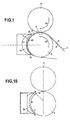
- FIG. 1 schematically shown an installation for manufacturing a sheet with fastening elements.
- a ply 1 with cylindrical rods for example of polygonal cross sections, for example square or rectangular, or elliptical, in particular circular, or similar and / or conical, is conveyed from a not shown rod ply forming device which comprises , conventionally, a forming roll, comprising cavities of complementary shapes of the rods that it is desired to form, and a pressure roller, rollers at a distance from one another to form a gap into which an extrusion is provided by thermoplastic material in the form of a material web neither fully hardened nor liquid to compress the material in the forming cavity, so that at the outlet is obtained by molding in the cavities the web 1 with rods with shaped rods complementary cavities, in particular of cylindrical shape, for example polygonal, in particular square or rectangular, or elliptical, in particular circular, and / or slightly c onic.
- This rod ply 1 is then conveyed (in particular by means of a return roller) into a first gap 2 (pre-gap) formed between a support roll 3 (prior support roll) and a first press roll 4 (pre-pressing roll).
- Both rolls have substantially the same diameter.
- the support roll 3 rotates at a rotation speed counterclockwise, so as to cause the web 1.
- the pressing roll 4 rotates in the opposite direction. It could also turn in the same direction.
- the gap 2 between the two rollers has a thickness constituted by the smallest distance measured between the two rollers along a line passing through their respective centers which is set to be less than the cumulative height of the web 5 of the web and of a rod 6 of the rod ply conveyed upstream of this gap.
- the pre-pressing roll 4 is heated to a temperature above the temperature of the support roll, which is preferably maintained at room temperature.
- the pre-pressing roll 4 is heated to a temperature of between 110 and 165 ° C. This temperature must be lower than the melting temperature of the thermoplastic material which passes between the two rollers and which forms the rod ply.
- the speed of rotation of the pre-pressing roll 4 and the speed of the prior support roll 3 are chosen so that the speed V 1, measured in the conveying direction of the web at the pre-gap, of the pressure roll is different.
- velocity V2 measured in the same conveying direction at the interstice (ie tangentially to the two rollers at the level where they form the gap), of the support roll.
- the speed V1 is greater than V2, in particular 5 to 20% higher, the speed V2 may especially be between 5 and 15m / min.
- the two speeds are directed in opposite directions, they are measured in the direction of V2, V1 then having negative and therefore less than V2.
- the rod ply becomes a ply with fastening elements or preforms comprising a base 5 and fastening elements 6 'consisting of a rod 7 and
- the head 8 protrudes from the rod in the forward direction with respect to the conveying direction.
- the sheet, still supported by the support roller 3, is conveyed into a second gap 10.
- This gap 10 extends along the circular periphery of the roll 3, on a circular arc of a length of 200 mm.
- This gap is formed between on the one hand a section of the outer surface of the support roller 3 and on the other hand a circular curved surface 11 in cross-section (plane of the figure) of a pressing element 12.
- the interstice extends between an entry point E and an exit point D.
- the thickness of the gap that is to say the distance between the two opposite surfaces, namely the surface 11 and the section 30 of the outer surface of the roll 3 decreases from point E to point D, is at to say decreases in the direction in which the band is conveyed.
- the thickness is measured in the radial direction (perpendicular to the tangent) of the outer surface of the roll 3. It is about 1 mm at the entrance and about 0.4 mm at the exit.
- the thickness is greater than the cumulative height of the strip 5 and a preform 6 'coming out of the first interstice.
- the ply enters a second length C whose thickness is equal to and then less than the cumulative height of the strip 5 and of a preform 6 ', so that contact occurs with the surface 11, contact whose pressure increases as one approaches the output D.
- this length C the final shape of the head is achieved.
- the pressing element 12 is fixed (zero displacement speed). It could also be mobile, however always so that its speed is less than V2 when measured in the direction of V2.
- the concavities of the facing surfaces 11 and 30 are turned in the same direction, ie toward the center of the support roller 3. At the limit, one or other of these two surfaces or both surfaces are straight or substantially rectilinear.
- the elements, in particular pressing, are generally made of metal material, especially hard. They can however also be of other materials that can withstand temperatures of the order of 160 ° C.
- the support roll is made of metal. It may, however, also be in any other material with temperatures of the order of 40 ° (rubber, thermoplastic, etc.).
- FIG 2 there is shown a longitudinal sectional view, that is to say in a plane which is both parallel to the MD direction (Machine Direction) and perpendicular to the base plane of the sheet, a preform sheet at the exit of the first interstice between the two rollers 3 and 4 for supporting and pressing beforehand.
- a preform 6 'coming from the base 5 of the ply in the vertical direction or perpendicular to the base consists of a rod 7 whose cross section, that is to say in a plane parallel to the base 5 is substantially constant or strictly decreasing towards its summit and up to its vertex (this is the case shown in the figures).
- This rod 7 is extended at its upper end or vertex by a portion 8 of the head which protrudes laterally from the rod 7.
- the head portion 8 protrudes from the front side (left in the figure) of the machine direction and does not protrude from the back side (or right side to the figure), and especially the back side has no snap capability.
- the part 8 of head has, seen from above as with the figure 3 , an upper surface having substantially an oval or elliptical section. It protrudes from the stem over most of the turn of the stem, with the exception of a back portion that extends over an arc around the stem corresponding to about 25% of the total circumference of the head.
- This percentage may, according to the invention, vary from 15% to 50%. This corresponds, in the case of a circular head with an angular section of between about 50 ° and 170 °, in particular about 90 °.
- the portion of the head that does not protrude is in this embodiment at the rear end, the precompressing roll rotating faster than the support roll.
- the rod may have a rectangular, square, polygonal, circular, oval or the like.
- it is rectangular having a ratio of its length to its width which is preferably between 1 and 2.
- its length is oriented in the direction MD and its width is oriented in the direction CD .
- each fastening element consists of a portion of rod 17 having a cross section (ie perpendicular to the direction in which extends the axis of the rod, which direction in this embodiment is vertical, knowing that it is quite possible within the context of the present invention that this axis of the rod is inclined relative to vertically) which is constant or decreasing.
- a head portion 18 of the hooking member protrudes laterally from the stem portion 17.
- a hook, mushroom or hooking element has two parts, namely a stem portion and a head portion that projects laterally from the rod.
- a stem portion and a head portion that projects laterally from the rod.
- the rear edge and the front edge are the lines with the points of the outer surface of the rod which are the most aft, respectively the most forward of the stem.
- the point M2 is defined as the point of the edge from which, when moving along the rear edge of the bottom of the stem (at the base) towards the high, the line forming the edge begins to have a curved shape, in particular oriented in a direction towards the rear relative to the part of the edge which is under this point M2, knowing that before this point M2 of delimitation , the rear edge is generally vertical (cylindrical rod) or inclined forward (conical rod).
- the point M1 corresponding to the point where the front edge begins to have a curved shape is defined, knowing that before this point the front edge is generally of shape. rectilinear vertical or inclined backward.
- the delimitation plane is then the plane comprising the line M1M2 and perpendicular and parallel to the direction CD.
- the cross section of the rod is rectangular or square and therefore comprises four corners
- two front points and two rear delimiting points of the head are defined on the respective edges of the rod.
- the two points correspond to the place where the front edges start to have a curved shape, after having a vertical rectilinear shape or inclined towards the rear.
- the line M1M2 which is inclined downwards and backwards, in particular at an angle of approximately 10 ° and which is in general between 1 ° and 20 °.
- the points M1 and M2 are double because there are two edges on each side (one edge per corner of the rectangle or square forming the section of the rod).
- a curve is defined corresponding to the lower surface of the head which projects from the rod to the right and to the left of the rod in the plane.
- Each curve on the right and on the left has a highest point Ph and a lowest point Pb respectively to the left or right of the highest point.
- the pronouncement of the hook, mushroom or fastening element in a given radial half-plane is defined as being the angle between the horizontal or the base plane of the web from which the element and the line passing through the two points Pb and Ph.
- the outer peripheral edge of the head is defined as the curve Cb comprising the set of points Pb.
- the largest attachment angle left or right is equal to a and is strictly positive, the straight line PhPb shown being inclined downwards in the radial left half plane of the figure 6 while the largest rear attachment angle b represented at the figure 5 is negative (the right PhPB shown being inclined upwards in the radial aft rear plane of the figure 5 ) and is therefore smaller than the angle a.
- the curve Cb which corresponds to the outer edge of the head, comprises a forward curved segment, a right intermediate segment 40, a left intermediate segment 41, a right lateral curved segment 21, a rear curved segment 22 and a curved segment 23 left lateral.
- the curve Ch (dashed at the figure 9 ) comprises a front curved segment (identical to the front curved segment of the curve Cb, since the head along this section does not project from the rod), a right intermediate segment 46, a right lateral curved segment, a segment 26 curved rear, a left-side curved segment 27 and an intermediate segment 47 left.
- the concavity of the front segment is turned forward.
- the concavity of the rear segment 22 is turned forward.
- the concavities of the segments 21, 22, 23, 25, 26, 27 are turned towards the rod.
- the concavity of the intermediate segments 40 to 47 is turned towards the outside of the element.
- the area delimited by the segments 40 and 42 and 41 and 43 respectively has a concave surface whose concavity is turned towards the outside of the element.
- the concavity of the rear segment 26 is turned forward.
- the concavities of the segments 25 and 27 are facing towards the rod.
- the curvature of the segment 26 is smaller than that of the segment 22 (the radius of curvature of the segment 26 is larger than segment 22).
- the curvature of the segment 21 is greater than that of the segment 25 (the radius of curvature of the segment 21 is smaller than that of the segment 25).
- the curvature of segment 23 is greater than that of segment 27 (the radius of curvature of segment 23 is smaller than that of segment 27).
- the pronounced head is substantially equal to zero.
- the pronouncement of the head is greater than the largest pronounced of the head on the rear segment.
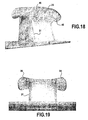
- the fastening element comprises a portion of rod 17 of cross section (parallel to the base strip from which the fastening element is derived) rectangular or square, having four corners.
- rod 17 of cross section parallel to the base strip from which the fastening element is derived
- four ridges 31 extend upwardly from the base substantially to the height from which the head portion 32 of the element extends. hooking.
- the cross section of the rod has a rectangular or square area which decreases from the base to the height where the head portion begins. It could also be constant.
- the head On two opposite sides in the CD direction (axis of view of the figure 12 ) the head has two wings 33, 34, the outer edges of which correspond to segments 21 and 23. On the front side in the MD direction (as shown in figure 12 ) the head does not protrude from the stem. From the back side in the MD direction (left at the figure 12 ) the head comprises an advanced portion whose outer edge corresponds to the section 22.
- the pronunciation of the attachment or angle of attachment of the wings at the furthest point of the rod in the direction CD is greater than all the pronounced latching of the advanced part.
- the upper surface of the head has on the rear side a concave region 36, the concavity is rotated in a direction away from the attachment element, especially upwards.
- This concave region is delimited at the rear by a ridge line 37 and forwardly by the stem, in particular by the section 20.
- the line 37 of peak consists of a right section 42, a central section and a left section 43.
- the two sections 42 and 43 right and left extend from the junction point of section 20 and sections respectively.
- 40 and 41 intermediate right and left up to two points 38 respective right and left vertex between which extends the central section of the crest line.
- This central section has a central point 49 the most rearward.
- two intermediate ridge lines 44 and 45 right and left connect the front ends of the edges or sections 21 and 23 of the right and left wings at the two points vertex 38 right and left respectively.
- the outer surface of the head comprises, in addition to the concave surface 36, two concave concave surface right and left concave surfaces facing outwards and which are delimited respectively by the sections 40, 42, 44 and 41, 43, 45.
- the two points 38 vertex are the two points of the upper surface of the highest attachment element.
- the presence of these two highest points 38 vertex has the advantage that they will guide the loops intended to cooperate with the fastening element, either to the fastening element immediately following forward, or to the wings 33, 34 so that the loops are particularly well attached to the fastening elements and a self gripping male female having excellent tensile and / or peel strength is obtained.
- two ribs 39 extend from the upper ends of the rear edges 31 of the rod to the outer edge (location of points Pb) of the head. These ribs are in the form of a thickening having a ridge line in continuity with the rear edges 31. They extend to the outer edge of the head at two points on the back side in the MD direction, laterally offset from the rod in the CD direction. These two ribs give the fastening element greater tensile and / or peel strength when it cooperates with loops.
- the upper surface of the head is convex with its convexity facing upwards, the region being delimited by the outer rear edge of the projection, by the outer edges of the two wings, by the portion of the ridge line 37 which extends between the two points 38 apex and by the two intermediate sections 44 and 45 peak.
- the two wings 33, 34 have an outer edge (place of the points Pb) which has the shape of a curved curve (it is about the sections 21 and 23) convex whose convexity is turned in the direction which moves away from the fastening element in the CD direction.
- the grip pronunciation angle is increasing from the points Pb below the end points 38 going backward in the MD direction. This growth of the angle of pronunciation takes place to an intermediate point corresponding substantially to the point of the convex curved curve of the edge of the wing which is farthest from the stem. Then, this pronunciation decreases to the ribs 39 where the outer edge ceases to be that of the wings to become that of the appendix which has a substantially zero pronunciation angle.
- the circle Ci written in the head is defined as being the circle whose center O1 is located midway between the end point before P1 in the direction MD in plan view of the attachment element (ie the point of the upper surface of the most forward head in the MD direction) and the rearmost point P2 in the MD direction in top view of the shackle (ie the point of the upper surface of the most rearward head in the direction MD) on the line passing through these two points and whose radius is equal to this mid distance.
- the outer peripheral edges of the left and right wings each extend over a length which corresponds to an arc B of circle on the circle Ci which is equal to the figure 8 at about 100 ° and which can be generally between 60 ° and 140 °.
- the outer peripheral edge of the forward portion extends over a length that corresponds to a circle arc C on the circle Ci which is equal to the figure 8 at about 80 ° and which can be generally between 40 ° and 120 °.
- the outer peripheral edge along which the head does not project from the stem extends over a length which corresponds to an arc A of circle on the circle Ci which is equal to the figure 8 at about 80 ° and which can be generally between 40 ° and 120 °.
Landscapes
- Engineering & Computer Science (AREA)
- Mechanical Engineering (AREA)
- Slide Fasteners, Snap Fasteners, And Hook Fasteners (AREA)
- Extrusion Moulding Of Plastics Or The Like (AREA)
Claims (13)
- Lage mit Befestigungselementen, die eine Basislage (5), insbesondere aus einem thermoplastischen Material, und mindestens ein aus der Lage hervorgehendes Befestigungselement aufweist, wobei das Befestigungselement aus einem Schaftteil (17) und einem Kopfteil (18) das seitlich von dem Schaft vorspringt, besteht, wobei der Kopf zwei Flügel, einen linken und einen rechten, (33, 34) aufweist, die seitlich von dem Kopf in einer Querrichtung, oder CD, vorstehen, wobei sie einen größten linken bzw. rechten Befestigungswinkel (a) aufweisen; und wobei der Kopf andererseits radial zwischen den beiden Flügeln ein hinteres Vorsprungteil (35)aufweist, das von dem Schaft auf der hinteren Seite in einer zur Richtung CD senkrechten Richtung MD vorsteht, wobei es einen größten hinteren Befestigungswinkel (b) aufweist, dadurch gekennzeichnet, dass der größte linke und der größte rechte Befestigungswinkel (a) größer als der größte hintere Befestigungswinkel (b) sind.
- Lage nach Anspruch 1, dadurch gekennzeichnet, dass der Kopf (18) in einem vorderen Teil, d.h. auf der zum Vorsprungteil (35) entgegengesetzten Seite, nicht seitlich von dem Schaft vorsteht.
- Lage nach einem der Ansprüche 1 oder 2, dadurch gekennzeichnet, dass der Schaft (17) eine im Wesentlichen rechteckige Querschnittsform aufweist.
- Lage nach Anspruch 3, dadurch gekennzeichnet, dass der Kopf (18) zwei Auswüchse in Rippenform (39) aufweist, die sich von den Kanten (31) des Schaftes, die durch dessen hintere Keile auf der Seite des Vorsprungteils gebildet werden, bis zum höchsten Punkt desselben erstrecken.
- Lage nach Anspruch 4, dadurch gekennzeichnet, dass jede Rippe (39) einen Kamm in Verbindung mit der jeweiligen Kante (31) des Schafts, von der aus sie sich erstreckt, aufweist.
- Lage nach einem der Ansprüche 3 bis 5, dadurch gekennzeichnet, dass die Abgrenzungsebene (M1M2) zwischen dem Kopf und dem Schaft in der Richtung nach hinten in Bezug auf die Basisebene (5) nach unten geneigt ist.
- Lage nach einem der Ansprüche 1 bis 6, dadurch gekennzeichnet, dass die obere Oberfläche des Kopfs (18) auf der zum Vorsprungteil entgegengesetzten Seite einen konkaven Bereich (36) aufweist, dessen Höhlung in eine Richtung, die sich vom Befestigungselement entfernt, gewandt ist, wobei dieser konkave Bereich nach hinten durch eine Kammlinie (37) und nach vorne durch die Schaft-Kopf-Abgrenzungsebene abgegrenzt ist.
- Lage nach Anspruch 7, dadurch gekennzeichnet, dass die Kammlinie (37) einen rechten und einen linken Gipfelpunkt (38) aufweist, die die beiden höchsten Punkte des Kopfes in Bezug auf rechts und links der Vorder/Hinterachse des Kopfs (18), die durch die Schaftachse (17) geht, sind.
- Lage nach Anspruch 8, dadurch gekennzeichnet, dass die beiden Punkte (38) näher am Vorderrand als am Hinterrand liegen.
- Lage nach einem der Ansprüche 5 bis 9, dadurch gekennzeichnet, dass auf der in Bezug zum konkaven Bereich (36) anderen Seite der Kammlinie (37), d.h. auf der in der MD-Richtung hinteren Seite, die obere Oberfläche des Kopfes konvex ist, wobei deren Wölbung nach oben gewandt ist, wobei der Bereich durch den hinteren Außenrand des Vorsprungs, durch die Außenränder der beiden Flügel, durch den Teil der Kammlinie (37), der sich zwischen den beiden Gipfelpunkten (38) erstreckt, und durch zwei Zwischenkammabschnitte (44) und (45) abgegrenzt ist.
- Verfahren zur Herstellung einer Lage mit Befestigungselementen nach einem der Ansprüche 1 bis 10, das die folgenden Stufen aufweist, wobei:eine Lage mit Vorformen bereitgestellt wird, die eine Basislage (5) und mindestens eine Vorform (6'), die quer, insbesondere im Wesentlichen senkrecht von der Lage vorsteht, aufweist, wobei die mindestens eine Vorform beispielsweise ein oder mehrere rundzylindrische oder konische Schäfte sind; diese Lage mit Vorformen durch einen Zwischenraum (E-D) .hindurchgeführt wird, der zwischen einer gekrümmten oder geraden Trägeroberfläche (11) eines Trägerelements, insbesondere einer Trägerwalze, wobei der Träger derart ist, dass die Lage mit der Trägeroberfläche über deren Seite ohne Vorform in Kontakt ist, und einer gekrümmten oder geraden Pressoberfläche eines Presselements (12) ausgebildet ist, wobei die Höhlung bzw. Wölbung der beiden Oberflächen in die gleiche Richtung gewandt ist, der Zwischenraum eine Eingangsdicke und eine gegenüber der Eingangsdicke geringere Ausgangsdicke aufweist, die Trägeroberfläche die Lage mit Vorformen mit einer Transportgeschwindigkeit transportiert, während die Pressoberfläche fest ist oder sich mit einer geringeren Geschwindigkeit als der Transportgeschwindigkeit verschiebt;die Gesamthöhe, die vom höchsten Punkt der Dicke der Basislage (5) und der Höhe der einzelnen Vorformen (6') gebildet wird, größer als die Dicke an einem zwischen dem Eingang und dem Ausgang gelegenen Punkt, wobei dieser Punkt der Eingang sein kann, ist und die Dicke des Zwischenraums von diesem Punkt in Richtung des Ausgangs, insbesondere bis zum Ausgang, derart abnimmt, dass die Vorformen durch in Richtung des Ausgangs zunehmenden Druck verformt werden, um auf diese Weise eine Lage mit Befestigungselementen zu erhalten.
- Verfahren nach Anspruch 11, dadurch gekennzeichnet, dass die Lage mit Vorformen, die in den Zwischenraum transportiert wird, dadurch erhalten wird, dass eine Lage mit Schäften, die eine Basislage (5) und Schäfte (6), die quer, insbesondere im Wesentlichen senkrecht von der Lage vorspringen, wobei sie insbesondere von zylindrischer Form, insbesondere runder oder konischer Form sind, aufweist, zwischen einem vorhergehenden Trägerelement, insbesondere einer vorgehenden Trägerwalze (3) und einem vorhergehenden Presselement, insbesondere einer vorhergehenden Presswalze (4) transportiert wird;
wobei zwischen den zwei vorhergehenden Träger- und Presselementen ein vorhergehender Zwischenraum (2) derart gebildet wird, dass die Schäfte (6) durch das vorhergehende Presselement gegen den vorhergehenden Träger derart gepresst werden, dass am Ausgang des vorhergehenden Zwischenraums eine Lage mit Vorformen erhalten wird, die eine Lage (5) und .Vorformen (6'), die an deren Ende ein Kopfteil (7), das seitlich vorsteht, aufweisen, aufweist, wobei die Höhe der Vorformen (6') geringer als die Höhe der Schäfte (6) vor dem vorhergehenden Zwischenraum zwischen den beiden vorhergehenden Träger- und Presselementen ist;
wobei sich das vorhergehende Trägerelement mit einer ersten Geschwindigkeit (V1), die in der Transportrichtung der Lage auf der Höhe des vorhergehenden Zwischenraums gemessen wird, verschiebt und das Druckelement sich mit einer zweiten Geschwindigkeit (V2), die in der Transportrichtung der Lage auf der Höhe des vorhergehenden Zwischenraums gemessen wird, verschiebt, wobei die beiden Geschwindigkeiten die gleiche Richtung aufweisen, jedoch voneinander verschieden sind. - Einrichtung zur Herstellung einer Lage mit Befestigungselementen nach einem der Ansprüche 1 bis 10, umfassend ein erstes Trägerelement, insbesondere eine Walze (3), mit einer gekrümmten oder geraden Trägeroberfläche und ein Presselement (12) mit einer gekrümmten oder geraden Pressoberfläche, wobei die beiden Träger- und Pressoberflächen derart angeordnet sind, dass deren Höhlung bzw. Wölbung in die gleiche Richtung gewandt ist und ein Zwischenraum (E-D) zwischen ihnen gebildet wird, und Mittel zum Transportieren einer Lage mit Vorformen, um diese durch den Zwischenraum zwischen den beiden Elementen derart zu führen, dass die Lage auf deren Seite ohne Vorformen getragen wird, wobei sich der Zwischenraum zwischen einem Eingang und einem Ausgang und mindestens über einen Abschnitt, vorzugsweise zwischen dem Eingang und dem Ausgang, erstreckt, wobei die Dicke des Zwischenraums in Richtung des Ausgangs abnimmt; wobei die Trägeroberfläche die Lage mit einer Transportgeschwindigkeit transportiert, während die Pressoberfläche mit der Geschwindigkeit null oder einer geringeren Geschwindigkeit als der Transportgeschwindigkeit verschoben wird.
Priority Applications (1)
| Application Number | Priority Date | Filing Date | Title |
|---|---|---|---|
| PL10723168T PL2429328T3 (pl) | 2009-05-15 | 2010-04-30 | Element do zaczepiania tworzący część obejmowaną elementu samo-przyczepnego |
Applications Claiming Priority (2)
| Application Number | Priority Date | Filing Date | Title |
|---|---|---|---|
| FR0902358A FR2945413B1 (fr) | 2009-05-15 | 2009-05-15 | Element d'accrochage pour former la partie male d'un auto-agrippant |
| PCT/FR2010/000339 WO2010130886A1 (fr) | 2009-05-15 | 2010-04-30 | Element d'accrochage pour former la partie male d'un auto-agrippant |
Publications (2)
| Publication Number | Publication Date |
|---|---|
| EP2429328A1 EP2429328A1 (de) | 2012-03-21 |
| EP2429328B1 true EP2429328B1 (de) | 2013-03-06 |
Family
ID=41365265
Family Applications (1)
| Application Number | Title | Priority Date | Filing Date |
|---|---|---|---|
| EP10723168A Active EP2429328B1 (de) | 2009-05-15 | 2010-04-30 | Verbindungselement zum bilden des steckabschnitts einer automatischen befestigungsvorrichtung |
Country Status (12)
| Country | Link |
|---|---|
| US (3) | US8935836B2 (de) |
| EP (1) | EP2429328B1 (de) |
| JP (1) | JP5619147B2 (de) |
| KR (3) | KR101723696B1 (de) |
| CN (2) | CN102421320B (de) |
| BR (1) | BRPI1010792B1 (de) |
| CA (2) | CA2992752C (de) |
| ES (1) | ES2404888T3 (de) |
| FR (1) | FR2945413B1 (de) |
| MX (1) | MX2011011798A (de) |
| PL (1) | PL2429328T3 (de) |
| WO (1) | WO2010130886A1 (de) |
Families Citing this family (15)
| Publication number | Priority date | Publication date | Assignee | Title |
|---|---|---|---|---|
| US6313664B1 (en) * | 2000-03-20 | 2001-11-06 | Motorola Inc. | Load capacitance compensated buffer, apparatus and method thereof |
| FR2945413B1 (fr) * | 2009-05-15 | 2011-05-06 | Aplix Sa | Element d'accrochage pour former la partie male d'un auto-agrippant |
| JP6192283B2 (ja) * | 2012-10-11 | 2017-09-06 | スリーエム イノベイティブ プロパティズ カンパニー | ファスナ部材 |
| FR2998628B1 (fr) * | 2012-11-28 | 2015-01-16 | Aplix Sa | Elements d accrochage moules et leur procede de fabrication |
| DK177596B1 (en) * | 2012-12-21 | 2013-11-11 | Unidrain As | Shower installation kit and method of installing shower |
| US9609920B2 (en) * | 2013-09-06 | 2017-04-04 | Kimberly-Clark Worldwide, Inc. | Process for modifying a hook profile of a fastening component and a fastening component having hooks with a modified profile |
| US10016022B2 (en) | 2015-10-07 | 2018-07-10 | Ykk Corporation | Hook fastener and methods for manufacturing same |
| TWI555477B (zh) * | 2015-12-03 | 2016-11-01 | Taiwan Paiho Ltd | Mushroom Head Shot Hook and Velcro with the Mushroom Head Shot |
| FR3050620B1 (fr) * | 2016-04-29 | 2019-08-02 | Aplix | Dispositif de retenue ameliore comprenant des elements de retenue renforces |
| WO2017187103A1 (fr) * | 2016-04-29 | 2017-11-02 | Aplix | Appareil de moulage pour la formation d'un dispositif de retenue |
| WO2018150493A1 (ja) * | 2017-02-15 | 2018-08-23 | Ykk株式会社 | 成形面ファスナー及び成形面ファスナーの製造方法、並びに成形装置 |
| KR102459920B1 (ko) | 2018-01-25 | 2022-10-27 | 삼성전자주식회사 | 저전력 에코 제거를 지원하는 애플리케이션 프로세서, 이를 포함하는 전자 장치 및 그 동작 방법 |
| US11819091B2 (en) | 2018-11-16 | 2023-11-21 | Ykk Corporation | Method for manufacturing molded surface fastener and molded surface fastener |
| FR3092518A1 (fr) | 2019-02-07 | 2020-08-14 | Aplix | Procédé de traitement amélioré pour un ruban présentant des éléments agrippant. |
| FR3150935A1 (fr) * | 2023-07-13 | 2025-01-17 | Aplix | Dispositif de retenue amélioré |
Family Cites Families (40)
| Publication number | Priority date | Publication date | Assignee | Title |
|---|---|---|---|---|
| US3708833A (en) * | 1971-03-15 | 1973-01-09 | American Velcro Inc | Separable fastening device |
| US4454183A (en) * | 1982-02-26 | 1984-06-12 | Minnesota Mining And Manufacturing Company | Strip material with heat-formed hooked heads |
| US4894060A (en) * | 1988-01-11 | 1990-01-16 | Minnesota Mining And Manufacturing Company | Disposable diaper with improved hook fastener portion |
| US5339499A (en) * | 1993-02-16 | 1994-08-23 | Velcro Industries B.V. | Hook design for a hook and loop fastener |
| JP2731103B2 (ja) * | 1993-09-08 | 1998-03-25 | ワイケイケイ株式会社 | 一体成形面ファスナー |
| JP3093938B2 (ja) * | 1994-11-01 | 2000-10-03 | ワイケイケイ株式会社 | 一体成形面ファスナーのフック片構造 |
| CN1055654C (zh) * | 1995-11-06 | 2000-08-23 | Ykk株式会社 | 成形表面扣件及其制造方法和设备 |
| JPH09121908A (ja) * | 1995-11-06 | 1997-05-13 | Ykk Corp | 成形面ファスナーとその製造方法及び装置 |
| JP3461662B2 (ja) * | 1996-06-06 | 2003-10-27 | Ykk株式会社 | 一体成形面ファスナー |
| US5900350A (en) * | 1996-06-06 | 1999-05-04 | Velcro Industries B.V. | Molding methods, molds and products |
| JP3494529B2 (ja) * | 1996-06-06 | 2004-02-09 | Ykk株式会社 | 一体成形面ファスナー |
| US6054091A (en) * | 1996-10-03 | 2000-04-25 | Minnesota Mining And Manufacturing Co. | J hook-type hook strip for a mechanical fastener |
| US6039911A (en) * | 1997-01-09 | 2000-03-21 | 3M Innovative Properties Company | Method for capping stem fasteners |
| US6132660A (en) * | 1997-06-19 | 2000-10-17 | 3M Innovative Properties Company | Method for forming headed stem mechanical fasteners |
| US5868987A (en) * | 1997-06-19 | 1999-02-09 | Minnesotamining And Manufacturing | Superimposed embossing of capped stem mechanical fastener structures |
| US6280670B1 (en) * | 1997-08-22 | 2001-08-28 | Velcro Industries B.V. | Post- forming heads on fastener elements |
| JP3901315B2 (ja) * | 1997-12-01 | 2007-04-04 | 花王株式会社 | メカニカルホックのオス側シート材 |
| JP3505074B2 (ja) * | 1998-01-22 | 2004-03-08 | Ykk株式会社 | 成形面ファスナー |
| DE19828856C1 (de) * | 1998-06-29 | 1999-10-07 | Binder Gottlieb Gmbh & Co | Verfahren zur Herstellung eines Haftverschlußteiles |
| US6991843B2 (en) * | 1999-01-15 | 2006-01-31 | Velcro Industries B.V. | Fasteners engageable with loops of nonwoven fabrics and with other open structures, and methods and machines for making fasteners |
| US6248276B1 (en) * | 1999-01-15 | 2001-06-19 | Velcro Industries B.V. | Fasteners and methods of making fasteners |
| JP2000225650A (ja) * | 1999-02-08 | 2000-08-15 | Ykk Corp | 平板状基材表面に起立する合成樹脂製突起物の二次成形装置 |
| US6601631B1 (en) * | 1999-09-07 | 2003-08-05 | Berol Corporation | Dispenser for applying a material to a surface |
| US6592800B1 (en) * | 1999-10-04 | 2003-07-15 | 3M Innovative Properties Company | Apparatus and method for making a mechanical fastener |
| US7794559B2 (en) * | 2000-03-14 | 2010-09-14 | Velcro Industries B.V. | Forming fastening projections on rigid substrates |
| JP3818431B2 (ja) * | 2001-03-08 | 2006-09-06 | Ykk株式会社 | 一体成形面ファスナーとその連続製造方法及び連続製造装置 |
| DE10123205A1 (de) * | 2001-05-12 | 2002-11-28 | Binder Gottlieb Gmbh & Co | Verfahren zur Herstellung eines Haftverschlußteils |
| USRE42475E1 (en) * | 2001-06-04 | 2011-06-21 | Velcro Industries B.V. | Fasteners engageable with loops of nonwoven fabrics and with other open structures, and methods and machines for making fasteners |
| ES2301130T3 (es) * | 2001-06-04 | 2008-06-16 | Velcro Industries B.V. | Componente de gancho y un metodo de fabricacion de un componente de gancho. |
| US6843944B2 (en) * | 2001-11-01 | 2005-01-18 | 3M Innovative Properties Company | Apparatus and method for capping wide web reclosable fasteners |
| US6687962B2 (en) * | 2002-01-16 | 2004-02-10 | Velcro Industries B.V. | Fastener element patterning |
| JP3892372B2 (ja) * | 2002-09-06 | 2007-03-14 | Ykk株式会社 | 一体成形面ファスナーとその製造装置 |
| US20040088835A1 (en) * | 2002-11-08 | 2004-05-13 | Tachauer Ernesto S. | Active fasteners |
| USD516952S1 (en) * | 2003-07-10 | 2006-03-14 | Velcro Industries B.V. | Touch fastener element |
| US7520033B2 (en) * | 2003-10-15 | 2009-04-21 | Velcro Industries B.V. | Multiple-crook male touch fastener elements |
| JP3108746U (ja) * | 2004-11-15 | 2005-04-28 | ▲シン▼遠 柯 | 面ファスナー部材 |
| US7516524B2 (en) * | 2005-03-11 | 2009-04-14 | Velcro Industries B.V. | Hook fastener components and methods of their manufacture |
| US8168103B2 (en) * | 2008-10-23 | 2012-05-01 | Taiwan Paiho Limited | Method for making mushroom-type hook strap and mushroom-type hook strap made thereby |
| FR2945413B1 (fr) * | 2009-05-15 | 2011-05-06 | Aplix Sa | Element d'accrochage pour former la partie male d'un auto-agrippant |
| CN103052331B (zh) * | 2010-07-27 | 2016-02-17 | 可乐丽粘扣带股份有限公司 | 临时固定功能优异的面搭扣件 |
-
2009
- 2009-05-15 FR FR0902358A patent/FR2945413B1/fr active Active
-
2010
- 2010-04-30 CA CA2992752A patent/CA2992752C/fr not_active Expired - Fee Related
- 2010-04-30 KR KR1020117027078A patent/KR101723696B1/ko active Active
- 2010-04-30 CN CN201080021127.1A patent/CN102421320B/zh active Active
- 2010-04-30 JP JP2012510326A patent/JP5619147B2/ja active Active
- 2010-04-30 WO PCT/FR2010/000339 patent/WO2010130886A1/fr not_active Ceased
- 2010-04-30 KR KR1020177008684A patent/KR20170039756A/ko not_active Abandoned
- 2010-04-30 CA CA2757379A patent/CA2757379C/fr not_active Expired - Fee Related
- 2010-04-30 ES ES10723168T patent/ES2404888T3/es active Active
- 2010-04-30 EP EP10723168A patent/EP2429328B1/de active Active
- 2010-04-30 CN CN201510958537.3A patent/CN105538573B/zh active Active
- 2010-04-30 PL PL10723168T patent/PL2429328T3/pl unknown
- 2010-04-30 US US13/318,378 patent/US8935836B2/en active Active
- 2010-04-30 KR KR1020187001362A patent/KR101931068B1/ko active Active
- 2010-04-30 MX MX2011011798A patent/MX2011011798A/es active IP Right Grant
- 2010-04-30 BR BRPI1010792-4A patent/BRPI1010792B1/pt active IP Right Grant
-
2014
- 2014-12-31 US US14/587,030 patent/US9908270B2/en active Active
-
2018
- 2018-02-12 US US15/894,158 patent/US10391685B2/en active Active
Also Published As
| Publication number | Publication date |
|---|---|
| JP5619147B2 (ja) | 2014-11-05 |
| US20120047695A1 (en) | 2012-03-01 |
| US10391685B2 (en) | 2019-08-27 |
| WO2010130886A1 (fr) | 2010-11-18 |
| CA2992752C (fr) | 2020-07-14 |
| ES2404888T3 (es) | 2013-05-29 |
| CN105538573B (zh) | 2017-10-03 |
| US20180162022A1 (en) | 2018-06-14 |
| KR101931068B1 (ko) | 2018-12-19 |
| FR2945413B1 (fr) | 2011-05-06 |
| KR20180009388A (ko) | 2018-01-26 |
| MX2011011798A (es) | 2011-11-29 |
| US8935836B2 (en) | 2015-01-20 |
| US20150151465A1 (en) | 2015-06-04 |
| US9908270B2 (en) | 2018-03-06 |
| KR101723696B1 (ko) | 2017-04-05 |
| CN105538573A (zh) | 2016-05-04 |
| EP2429328A1 (de) | 2012-03-21 |
| JP2012526577A (ja) | 2012-11-01 |
| BRPI1010792A2 (pt) | 2016-03-29 |
| CA2757379A1 (fr) | 2010-11-18 |
| FR2945413A1 (fr) | 2010-11-19 |
| CN102421320B (zh) | 2016-01-20 |
| BRPI1010792B1 (pt) | 2020-02-27 |
| CA2757379C (fr) | 2018-06-19 |
| KR20170039756A (ko) | 2017-04-11 |
| PL2429328T3 (pl) | 2013-08-30 |
| CA2992752A1 (fr) | 2010-11-18 |
| KR20120018322A (ko) | 2012-03-02 |
| CN102421320A (zh) | 2012-04-18 |
Similar Documents
| Publication | Publication Date | Title |
|---|---|---|
| CA2757379C (fr) | Element d'accrochage pour former la partie male d'un auto-agrippant | |
| EP3448194B1 (de) | Verbesserte befestigungsvorrichtung mit verstärkten befestigungselementen | |
| EP2651630B1 (de) | Verfahren und vorrichtung zur herstellung eines reifens unter verwendung einer lage aus zwei kautschukzusammensetzungen | |
| EP1931842B1 (de) | Satz von profilen | |
| EP1493348A1 (de) | Verfahren zur Herstellung eines langlebigen pilzartigen Flächenreissverschlusses und so hergestellter Flächenreissverschluss | |
| WO2025012582A1 (fr) | Dispositif de retenue ameliore | |
| WO2017029445A1 (fr) | Procédé de fabrication d'un cadre de forme annulaire | |
| BE1016764A6 (fr) | Ensemble de profiles. | |
| CA2304400A1 (fr) | Bande oblongue formant partie auto-agrippante male, cylindre a former pour sa fabrication et procede de fabrication d'une bande de ce genre | |
| CA2563591A1 (fr) | Film a filaments individuels ancres. | |
| FR2952791A1 (fr) | Partie femelle a boucles a film et filaments ancres par thermotraction | |
| FR3050622B1 (fr) | Appareillage et procede pour la solidarisation d'un substrat a un ruban plastique | |
| FR3050679A1 (fr) | Appareil de moulage pour la formation d'un dispositif de retenue |
Legal Events
| Date | Code | Title | Description |
|---|---|---|---|
| PUAI | Public reference made under article 153(3) epc to a published international application that has entered the european phase |
Free format text: ORIGINAL CODE: 0009012 |
|
| 17P | Request for examination filed |
Effective date: 20111108 |
|
| AK | Designated contracting states |
Kind code of ref document: A1 Designated state(s): AT BE BG CH CY CZ DE DK EE ES FI FR GB GR HR HU IE IS IT LI LT LU LV MC MK MT NL NO PL PT RO SE SI SK SM TR |
|
| DAX | Request for extension of the european patent (deleted) | ||
| GRAP | Despatch of communication of intention to grant a patent |
Free format text: ORIGINAL CODE: EPIDOSNIGR1 |
|
| GRAS | Grant fee paid |
Free format text: ORIGINAL CODE: EPIDOSNIGR3 |
|
| GRAP | Despatch of communication of intention to grant a patent |
Free format text: ORIGINAL CODE: EPIDOSNIGR1 |
|
| GRAA | (expected) grant |
Free format text: ORIGINAL CODE: 0009210 |
|
| AK | Designated contracting states |
Kind code of ref document: B1 Designated state(s): AT BE BG CH CY CZ DE DK EE ES FI FR GB GR HR HU IE IS IT LI LT LU LV MC MK MT NL NO PL PT RO SE SI SK SM TR |
|
| REG | Reference to a national code |
Ref country code: GB Ref legal event code: FG4D Free format text: NOT ENGLISH |
|
| REG | Reference to a national code |
Ref country code: CH Ref legal event code: EP Ref country code: AT Ref legal event code: REF Ref document number: 599113 Country of ref document: AT Kind code of ref document: T Effective date: 20130315 |
|
| REG | Reference to a national code |
Ref country code: IE Ref legal event code: FG4D Free format text: LANGUAGE OF EP DOCUMENT: FRENCH |
|
| REG | Reference to a national code |
Ref country code: SE Ref legal event code: TRGR |
|
| REG | Reference to a national code |
Ref country code: DE Ref legal event code: R096 Ref document number: 602010005321 Country of ref document: DE Effective date: 20130502 |
|
| REG | Reference to a national code |
Ref country code: ES Ref legal event code: FG2A Ref document number: 2404888 Country of ref document: ES Kind code of ref document: T3 Effective date: 20130529 |
|
| REG | Reference to a national code |
Ref country code: AT Ref legal event code: MK05 Ref document number: 599113 Country of ref document: AT Kind code of ref document: T Effective date: 20130306 |
|
| PG25 | Lapsed in a contracting state [announced via postgrant information from national office to epo] |
Ref country code: AT Free format text: LAPSE BECAUSE OF FAILURE TO SUBMIT A TRANSLATION OF THE DESCRIPTION OR TO PAY THE FEE WITHIN THE PRESCRIBED TIME-LIMIT Effective date: 20130306 Ref country code: NO Free format text: LAPSE BECAUSE OF FAILURE TO SUBMIT A TRANSLATION OF THE DESCRIPTION OR TO PAY THE FEE WITHIN THE PRESCRIBED TIME-LIMIT Effective date: 20130606 Ref country code: LT Free format text: LAPSE BECAUSE OF FAILURE TO SUBMIT A TRANSLATION OF THE DESCRIPTION OR TO PAY THE FEE WITHIN THE PRESCRIBED TIME-LIMIT Effective date: 20130306 Ref country code: BG Free format text: LAPSE BECAUSE OF FAILURE TO SUBMIT A TRANSLATION OF THE DESCRIPTION OR TO PAY THE FEE WITHIN THE PRESCRIBED TIME-LIMIT Effective date: 20130606 |
|
| REG | Reference to a national code |
Ref country code: NL Ref legal event code: VDEP Effective date: 20130306 |
|
| REG | Reference to a national code |
Ref country code: LT Ref legal event code: MG4D |
|
| PG25 | Lapsed in a contracting state [announced via postgrant information from national office to epo] |
Ref country code: FI Free format text: LAPSE BECAUSE OF FAILURE TO SUBMIT A TRANSLATION OF THE DESCRIPTION OR TO PAY THE FEE WITHIN THE PRESCRIBED TIME-LIMIT Effective date: 20130306 Ref country code: SI Free format text: LAPSE BECAUSE OF FAILURE TO SUBMIT A TRANSLATION OF THE DESCRIPTION OR TO PAY THE FEE WITHIN THE PRESCRIBED TIME-LIMIT Effective date: 20130306 Ref country code: LV Free format text: LAPSE BECAUSE OF FAILURE TO SUBMIT A TRANSLATION OF THE DESCRIPTION OR TO PAY THE FEE WITHIN THE PRESCRIBED TIME-LIMIT Effective date: 20130306 Ref country code: GR Free format text: LAPSE BECAUSE OF FAILURE TO SUBMIT A TRANSLATION OF THE DESCRIPTION OR TO PAY THE FEE WITHIN THE PRESCRIBED TIME-LIMIT Effective date: 20130607 |
|
| REG | Reference to a national code |
Ref country code: PL Ref legal event code: T3 |
|
| PG25 | Lapsed in a contracting state [announced via postgrant information from national office to epo] |
Ref country code: HR Free format text: LAPSE BECAUSE OF FAILURE TO SUBMIT A TRANSLATION OF THE DESCRIPTION OR TO PAY THE FEE WITHIN THE PRESCRIBED TIME-LIMIT Effective date: 20130306 |
|
| PG25 | Lapsed in a contracting state [announced via postgrant information from national office to epo] |
Ref country code: PT Free format text: LAPSE BECAUSE OF FAILURE TO SUBMIT A TRANSLATION OF THE DESCRIPTION OR TO PAY THE FEE WITHIN THE PRESCRIBED TIME-LIMIT Effective date: 20130708 Ref country code: SK Free format text: LAPSE BECAUSE OF FAILURE TO SUBMIT A TRANSLATION OF THE DESCRIPTION OR TO PAY THE FEE WITHIN THE PRESCRIBED TIME-LIMIT Effective date: 20130306 Ref country code: NL Free format text: LAPSE BECAUSE OF FAILURE TO SUBMIT A TRANSLATION OF THE DESCRIPTION OR TO PAY THE FEE WITHIN THE PRESCRIBED TIME-LIMIT Effective date: 20130306 Ref country code: IS Free format text: LAPSE BECAUSE OF FAILURE TO SUBMIT A TRANSLATION OF THE DESCRIPTION OR TO PAY THE FEE WITHIN THE PRESCRIBED TIME-LIMIT Effective date: 20130706 Ref country code: EE Free format text: LAPSE BECAUSE OF FAILURE TO SUBMIT A TRANSLATION OF THE DESCRIPTION OR TO PAY THE FEE WITHIN THE PRESCRIBED TIME-LIMIT Effective date: 20130306 Ref country code: RO Free format text: LAPSE BECAUSE OF FAILURE TO SUBMIT A TRANSLATION OF THE DESCRIPTION OR TO PAY THE FEE WITHIN THE PRESCRIBED TIME-LIMIT Effective date: 20130306 |
|
| PG25 | Lapsed in a contracting state [announced via postgrant information from national office to epo] |
Ref country code: MC Free format text: LAPSE BECAUSE OF FAILURE TO SUBMIT A TRANSLATION OF THE DESCRIPTION OR TO PAY THE FEE WITHIN THE PRESCRIBED TIME-LIMIT Effective date: 20130306 |
|
| PLBE | No opposition filed within time limit |
Free format text: ORIGINAL CODE: 0009261 |
|
| STAA | Information on the status of an ep patent application or granted ep patent |
Free format text: STATUS: NO OPPOSITION FILED WITHIN TIME LIMIT |
|
| REG | Reference to a national code |
Ref country code: IE Ref legal event code: MM4A |
|
| PG25 | Lapsed in a contracting state [announced via postgrant information from national office to epo] |
Ref country code: DK Free format text: LAPSE BECAUSE OF FAILURE TO SUBMIT A TRANSLATION OF THE DESCRIPTION OR TO PAY THE FEE WITHIN THE PRESCRIBED TIME-LIMIT Effective date: 20130306 |
|
| 26N | No opposition filed |
Effective date: 20131209 |
|
| REG | Reference to a national code |
Ref country code: DE Ref legal event code: R097 Ref document number: 602010005321 Country of ref document: DE Effective date: 20131209 |
|
| PG25 | Lapsed in a contracting state [announced via postgrant information from national office to epo] |
Ref country code: IE Free format text: LAPSE BECAUSE OF NON-PAYMENT OF DUE FEES Effective date: 20130430 |
|
| REG | Reference to a national code |
Ref country code: CH Ref legal event code: PL |
|
| PG25 | Lapsed in a contracting state [announced via postgrant information from national office to epo] |
Ref country code: LI Free format text: LAPSE BECAUSE OF NON-PAYMENT OF DUE FEES Effective date: 20140430 Ref country code: CH Free format text: LAPSE BECAUSE OF NON-PAYMENT OF DUE FEES Effective date: 20140430 |
|
| PG25 | Lapsed in a contracting state [announced via postgrant information from national office to epo] |
Ref country code: MT Free format text: LAPSE BECAUSE OF FAILURE TO SUBMIT A TRANSLATION OF THE DESCRIPTION OR TO PAY THE FEE WITHIN THE PRESCRIBED TIME-LIMIT Effective date: 20130306 |
|
| PG25 | Lapsed in a contracting state [announced via postgrant information from national office to epo] |
Ref country code: SM Free format text: LAPSE BECAUSE OF FAILURE TO SUBMIT A TRANSLATION OF THE DESCRIPTION OR TO PAY THE FEE WITHIN THE PRESCRIBED TIME-LIMIT Effective date: 20130306 |
|
| PG25 | Lapsed in a contracting state [announced via postgrant information from national office to epo] |
Ref country code: CY Free format text: LAPSE BECAUSE OF FAILURE TO SUBMIT A TRANSLATION OF THE DESCRIPTION OR TO PAY THE FEE WITHIN THE PRESCRIBED TIME-LIMIT Effective date: 20130306 |
|
| PG25 | Lapsed in a contracting state [announced via postgrant information from national office to epo] |
Ref country code: LU Free format text: LAPSE BECAUSE OF NON-PAYMENT OF DUE FEES Effective date: 20130430 Ref country code: MK Free format text: LAPSE BECAUSE OF FAILURE TO SUBMIT A TRANSLATION OF THE DESCRIPTION OR TO PAY THE FEE WITHIN THE PRESCRIBED TIME-LIMIT Effective date: 20130306 Ref country code: HU Free format text: LAPSE BECAUSE OF FAILURE TO SUBMIT A TRANSLATION OF THE DESCRIPTION OR TO PAY THE FEE WITHIN THE PRESCRIBED TIME-LIMIT; INVALID AB INITIO Effective date: 20100430 |
|
| REG | Reference to a national code |
Ref country code: FR Ref legal event code: PLFP Year of fee payment: 7 |
|
| REG | Reference to a national code |
Ref country code: FR Ref legal event code: PLFP Year of fee payment: 8 |
|
| REG | Reference to a national code |
Ref country code: FR Ref legal event code: PLFP Year of fee payment: 9 |
|
| PGFP | Annual fee paid to national office [announced via postgrant information from national office to epo] |
Ref country code: GB Payment date: 20180417 Year of fee payment: 9 |
|
| GBPC | Gb: european patent ceased through non-payment of renewal fee |
Effective date: 20190430 |
|
| PG25 | Lapsed in a contracting state [announced via postgrant information from national office to epo] |
Ref country code: GB Free format text: LAPSE BECAUSE OF NON-PAYMENT OF DUE FEES Effective date: 20190430 |
|
| PGFP | Annual fee paid to national office [announced via postgrant information from national office to epo] |
Ref country code: CZ Payment date: 20210316 Year of fee payment: 12 |
|
| PG25 | Lapsed in a contracting state [announced via postgrant information from national office to epo] |
Ref country code: CZ Free format text: LAPSE BECAUSE OF NON-PAYMENT OF DUE FEES Effective date: 20220430 |
|
| PGFP | Annual fee paid to national office [announced via postgrant information from national office to epo] |
Ref country code: PL Payment date: 20230323 Year of fee payment: 14 |
|
| P01 | Opt-out of the competence of the unified patent court (upc) registered |
Effective date: 20230517 |
|
| PGFP | Annual fee paid to national office [announced via postgrant information from national office to epo] |
Ref country code: SE Payment date: 20240423 Year of fee payment: 15 Ref country code: BE Payment date: 20240415 Year of fee payment: 15 |
|
| PG25 | Lapsed in a contracting state [announced via postgrant information from national office to epo] |
Ref country code: PL Free format text: LAPSE BECAUSE OF NON-PAYMENT OF DUE FEES Effective date: 20240430 |
|
| PGFP | Annual fee paid to national office [announced via postgrant information from national office to epo] |
Ref country code: DE Payment date: 20250411 Year of fee payment: 16 |
|
| PGFP | Annual fee paid to national office [announced via postgrant information from national office to epo] |
Ref country code: ES Payment date: 20250512 Year of fee payment: 16 |
|
| PGFP | Annual fee paid to national office [announced via postgrant information from national office to epo] |
Ref country code: IT Payment date: 20250409 Year of fee payment: 16 |
|
| PGFP | Annual fee paid to national office [announced via postgrant information from national office to epo] |
Ref country code: FR Payment date: 20250422 Year of fee payment: 16 |
|
| REG | Reference to a national code |
Ref country code: BE Ref legal event code: MM Effective date: 20250430 |
|
| PG25 | Lapsed in a contracting state [announced via postgrant information from national office to epo] |
Ref country code: BE Free format text: LAPSE BECAUSE OF NON-PAYMENT OF DUE FEES Effective date: 20250430 |
|
| PG25 | Lapsed in a contracting state [announced via postgrant information from national office to epo] |
Ref country code: SE Free format text: LAPSE BECAUSE OF NON-PAYMENT OF DUE FEES Effective date: 20250501 |
|
| REG | Reference to a national code |
Ref country code: SE Ref legal event code: EUG |
|
| PGFP | Annual fee paid to national office [announced via postgrant information from national office to epo] |
Ref country code: TR Payment date: 20260318 Year of fee payment: 17 |