EP2428780A2 - Integrierte Kaltstellenkompensationsschaltung für Thermoelementverbindungen - Google Patents
Integrierte Kaltstellenkompensationsschaltung für Thermoelementverbindungen Download PDFInfo
- Publication number
- EP2428780A2 EP2428780A2 EP11179575A EP11179575A EP2428780A2 EP 2428780 A2 EP2428780 A2 EP 2428780A2 EP 11179575 A EP11179575 A EP 11179575A EP 11179575 A EP11179575 A EP 11179575A EP 2428780 A2 EP2428780 A2 EP 2428780A2
- Authority
- EP
- European Patent Office
- Prior art keywords
- thermocouple
- temperature
- temperature sensor
- cold junction
- terminal block
- Prior art date
- Legal status (The legal status is an assumption and is not a legal conclusion. Google has not performed a legal analysis and makes no representation as to the accuracy of the status listed.)
- Withdrawn
Links
- 238000004891 communication Methods 0.000 claims description 36
- 239000000758 substrate Substances 0.000 claims description 28
- 239000012080 ambient air Substances 0.000 claims description 4
- 238000002955 isolation Methods 0.000 abstract description 4
- 230000006870 function Effects 0.000 description 9
- 239000002184 metal Substances 0.000 description 9
- 229910052751 metal Inorganic materials 0.000 description 9
- 239000000463 material Substances 0.000 description 7
- 238000003860 storage Methods 0.000 description 7
- 150000002739 metals Chemical class 0.000 description 6
- RYGMFSIKBFXOCR-UHFFFAOYSA-N Copper Chemical compound [Cu] RYGMFSIKBFXOCR-UHFFFAOYSA-N 0.000 description 5
- 229910052802 copper Inorganic materials 0.000 description 5
- 239000010949 copper Substances 0.000 description 5
- 238000000034 method Methods 0.000 description 5
- 238000012545 processing Methods 0.000 description 5
- 229910001006 Constantan Inorganic materials 0.000 description 4
- 238000004364 calculation method Methods 0.000 description 4
- 238000005259 measurement Methods 0.000 description 4
- 230000009471 action Effects 0.000 description 3
- 230000005405 multipole Effects 0.000 description 3
- 230000008569 process Effects 0.000 description 3
- XEEYBQQBJWHFJM-UHFFFAOYSA-N Iron Chemical compound [Fe] XEEYBQQBJWHFJM-UHFFFAOYSA-N 0.000 description 2
- 238000009529 body temperature measurement Methods 0.000 description 2
- 239000004020 conductor Substances 0.000 description 2
- 230000000694 effects Effects 0.000 description 2
- 238000005516 engineering process Methods 0.000 description 2
- 230000007613 environmental effect Effects 0.000 description 2
- 238000000465 moulding Methods 0.000 description 2
- 239000000523 sample Substances 0.000 description 2
- 229910000809 Alumel Inorganic materials 0.000 description 1
- ATJFFYVFTNAWJD-UHFFFAOYSA-N Tin Chemical compound [Sn] ATJFFYVFTNAWJD-UHFFFAOYSA-N 0.000 description 1
- 229910045601 alloy Inorganic materials 0.000 description 1
- 239000000956 alloy Substances 0.000 description 1
- 230000005540 biological transmission Effects 0.000 description 1
- 238000006243 chemical reaction Methods 0.000 description 1
- 238000004590 computer program Methods 0.000 description 1
- 238000013500 data storage Methods 0.000 description 1
- 230000006837 decompression Effects 0.000 description 1
- 238000013461 design Methods 0.000 description 1
- -1 for example Substances 0.000 description 1
- 230000010365 information processing Effects 0.000 description 1
- 238000003780 insertion Methods 0.000 description 1
- 230000037431 insertion Effects 0.000 description 1
- 238000009434 installation Methods 0.000 description 1
- 230000010354 integration Effects 0.000 description 1
- 229910052742 iron Inorganic materials 0.000 description 1
- 238000004519 manufacturing process Methods 0.000 description 1
- 238000012986 modification Methods 0.000 description 1
- 230000004048 modification Effects 0.000 description 1
- 239000003607 modifier Substances 0.000 description 1
- 230000003287 optical effect Effects 0.000 description 1
- 230000037361 pathway Effects 0.000 description 1
- 238000005476 soldering Methods 0.000 description 1
- 229910052718 tin Inorganic materials 0.000 description 1
- 238000013519 translation Methods 0.000 description 1
- 238000003466 welding Methods 0.000 description 1
Images


Classifications
-
- G—PHYSICS
- G01—MEASURING; TESTING
- G01K—MEASURING TEMPERATURE; MEASURING QUANTITY OF HEAT; THERMALLY-SENSITIVE ELEMENTS NOT OTHERWISE PROVIDED FOR
- G01K7/00—Measuring temperature based on the use of electric or magnetic elements directly sensitive to heat ; Power supply therefor, e.g. using thermoelectric elements
- G01K7/02—Measuring temperature based on the use of electric or magnetic elements directly sensitive to heat ; Power supply therefor, e.g. using thermoelectric elements using thermoelectric elements, e.g. thermocouples
- G01K7/10—Arrangements for compensating for auxiliary variables, e.g. length of lead
- G01K7/12—Arrangements with respect to the cold junction, e.g. preventing influence of temperature of surrounding air
- G01K7/13—Circuits for cold-junction compensation
-
- G—PHYSICS
- G01—MEASURING; TESTING
- G01K—MEASURING TEMPERATURE; MEASURING QUANTITY OF HEAT; THERMALLY-SENSITIVE ELEMENTS NOT OTHERWISE PROVIDED FOR
- G01K7/00—Measuring temperature based on the use of electric or magnetic elements directly sensitive to heat ; Power supply therefor, e.g. using thermoelectric elements
- G01K7/02—Measuring temperature based on the use of electric or magnetic elements directly sensitive to heat ; Power supply therefor, e.g. using thermoelectric elements using thermoelectric elements, e.g. thermocouples
- G01K7/023—Measuring temperature based on the use of electric or magnetic elements directly sensitive to heat ; Power supply therefor, e.g. using thermoelectric elements using thermoelectric elements, e.g. thermocouples provided with specially adapted connectors
Definitions
- the disclosure relates generally to temperature measurement devices. More particularly, the invention relates to a cold junction compensation (CJC) circuit for thermocouple connections.
- CJC cold junction compensation
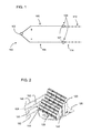
- thermocouple 100 is composed of two different thermocouple wires 102, 104 made of dissimilar metals. Wire 102 is designated positive, and wire 104 is designated negative. The positive and negative designations refer to the Seebeck coefficients of the respective metals of which the wires are made.
- Thermocouple wires 102, 104 are joined at tip 106, e.g., by soldering, welding, or other means. At screw terminals 107, the open ends of wires 102, 104 may electrically connect to wires or traces 112, 114, which may be made of copper or other electrically conductive material.
- a cold junction 108, or reference junction is formed here at the termination of dissimilar material wires, e.g., between wires 102, 112; and between wires 104, 114.
- thermocouples In a closed circuit, current is produced when the hot and cold junctions are maintained at different temperatures. Typically, specific metals and alloys are paired to form the junctions, due to their predictable and repeatable relationship between temperature and voltage.
- Thermocouples may be made from a variety of materials including, for example, iron, constantan, copper, and tin.
- the type and gauge size of the material used for the thermocouple is typically classified by a letter code, such as T (copper-constantan), J (iron-constantan), E (chromel-constantan), and K (chromel-alumel), for example, which have different voltage-temperature characteristics.
- Thermocouples measure the temperature difference between two points, rather than absolute temperature.
- the cold junction temperature In order to determine the temperature at the hot junction, the cold junction temperature must be known. In a simplest case, the cold junction is at 0°C (32°F), e.g., in an ice bath. In such a case, the hot junction temperature is a direct translation of the cold junction temperature, and can be found using lookup tables such as those published by the National Bureau of Standards.
- having a junction of known temperature while useful for laboratory calibration, is inconvenient for most measurement and control applications, particularly in lightweight, hand-held devices and permanent installations in which temperatures at the cold junction vary.
- thermocouple 100 When the cold junction is not at 0°C, the temperature of the cold junction must be found in order to determine the actual hot junction temperature. The output voltage of thermocouple 100 must also be compensated for in order to account for the voltage created by the nonzero cold junction temperature. This process is known as cold junction compensation.
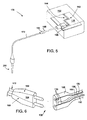
- FIG. 2 which depicts a multi-pole terminal block 120 mounted to printed circuit board 126
- one solution has been to mount external temperature sensors, such as thermistors 122, 124, to printed circuit board 126 at opposite ends of terminal strip 128.
- these thermistors 122, 124 may not be located near enough to cold junction 108, located at the termination of thermocouple extension wires 180, 182 at terminal block 120, to accurately acquire the actual cold junction temperature.
- thermistors 122, 124 may depend on one or a combination of environmental conditions, including temperature gradient across the distance of the terminal strip where cold junction 108 occurs.
- a first aspect of the disclosure provides apparatus comprising a substrate; a terminal block mounted to the substrate; a thermocouple having a thermocouple wire terminating at the terminal block, forming a cold junction; and at least one temperature sensor integrated with a surface of the terminal block.
- the at least one temperature sensor is located proximal to the cold junction, wherein a temperature at the cold junction is substantially equal to a temperature at the at least one temperature sensor.
- the at least one temperature sensor is placed in electrical signal communication with the substrate by a plurality of conductive pins.
- a second aspect of the disclosure provides a cold junction compensation (CJC) system.
- the CJC system comprises a thermocouple having a positive thermocouple wire and a negative thermocouple wire, the thermocouple being in electrical signal communication with a terminal block.
- the thermocouple outputs a voltage to the terminal block, which is mounted to, and in electrical signal communication with, a first tracing on a printed circuit board (PCB).
- PCB printed circuit board
- At least one temperature sensor is integrated with the terminal block, wherein each of the at least one temperature sensors is located proximal to a cold junction of the thermocouple, wherein a temperature at the cold junction is substantially equal to a temperature at the at least one temperature sensor.
- the at least one temperature sensor is in electrical signal communication with a second tracing on the PCB.
- a computing device for calculating a hot junction temperature is also included, the computing device being in electrical signal communication with the first tracing and the second tracing.
- the computing device receives an electrical signal representing an output voltage from the thermocouple via the first tracing pair, and an electrical signal representing the cold junction temperature from the temperature sensor via the second tracing pair.
- a third aspect of the disclosure provides a cold junction compensation system comprising a thermocouple having a first, positive wire and a second, negative wire joined at a first end of each of the first and second wires to form a first, hot junction; a first thermocouple extension wire electrically connected to the first, positive wire; a second thermocouple extension wire electrically connected to the second, negative wire; a male connector body in electrical communication with the first thermocouple extension wire and the second thermocouple extension wire; and a female connector body into which the male connector body is inserted, forming a cold junction.
- the female connector body includes a temperature sensor located proximal to the cold junction, wherein a temperature at the cold junction is substantially equal to a temperature at the temperature sensor.
- the female connector body includes an electrical contact that is made of a dissimilar metal from the first and the second thermocouple extension wire.
- a first temperature sensor wire and a second temperature sensor wire communicate a cold junction reference signal to a connector, and a first extension wire and a second extension wire communicate an output voltage signal to the connector.
- the connector is mounted to a substrate.
- a computing device for carrying out a cold junction compensation calculation is also included, wherein the computing device is in electrical signal communication with the substrate.
- thermocouple cold junction compensation circuit At least one embodiment of the present invention is described below in reference to its application in connection with the operation of a thermocouple cold junction compensation circuit. Although some of the embodiments of the invention are described herein and illustrated relative to a thermocouple in electrical communication with a printed circuit board, it is understood that the teachings are equally applicable to other substrates. Further, at least one embodiment of the present invention is described below in reference to a nominal size and including a set of nominal dimensions. However, it should be apparent to those skilled in the art that the present invention is likewise applicable to any suitable thermocouple cold junction measurement apparatus and/or device. Further, it should be apparent to those skilled in the art that the present invention is likewise applicable to various scales of the nominal size and/or nominal dimensions.
- aspects of the invention provide an apparatus for providing a reference temperature at a thermocouple cold junction 108, shown in FIGS. 3-5 .
- FIG. 3 embodiments of an apparatus 110 for providing a reference temperature at a cold junction 108 of a thermocouple ( FIG. 1 ) are depicted.
- thermocouple such as the one depicted in FIG. 1 , may include thermocouple extension wires 180, 182 ( FIG. 3 ), extending the reach of the thermocouple wires.
- Thermocouple extension wires 180, 182 are made of the same materials as thermocouple wires 102, 104 ( FIG. 1 ) respectively, such that thermocouple wire 180 is positive and thermocouple wire 182 is negative.
- cold junction 108A-B occurs at a junction of dissimilar metals at terminal block 134, where thermocouple extension wires 180, 182 may contact, e.g., a copper conductive wire.
- thermocouple wires 102, 104 may terminate at cold junction 108A-B in an alternative embodiment.
- Thermocouple 100 may output electrical energy at a voltage denoted V TC to terminal block 134.
- terminal block 134 may be physically mounted to a substrate 132, which may be, for example, a printed circuit board (PCB) including first pair of tracings 142 and second pair of tracings 144 thereon made of copper or other conductive material.
- a substrate 132 which may be, for example, a printed circuit board (PCB) including first pair of tracings 142 and second pair of tracings 144 thereon made of copper or other conductive material.
- Terminal block 134 may be in electrical signal communication with substrate 132, via a first tracing pair 142 and conductive pins or feet (not pictured) as is known in the art.
- PCB printed circuit board
- thermocouple extension wires 180, 182 may terminate at a terminal block plug 140.
- a sensor 136B may be integrated with a surface of a terminal block plug 140 in a manner similar to that described above.
- Terminal block plug 140 may plug into terminal block header 135, which may be mounted to substrate 132 in a manner similar to terminal block 134.
- the use of a terminal block 134 or a terminal block plug 140 and terminal block header 135 is a design choice, and depiction of either in various embodiments herein is intended to be non-limiting and merely exemplary.
- Tracings 142 carry output electric force generated by thermocouple 100 at voltage V TC away from terminal block 134.
- at least one temperature sensor 136A is integrated with a surface of terminal block 134 proximal to, or coincidentally with cold junction 108A. Relative to cold junction 108A, proximal placement of temperature sensor 136A may be such that any physical or environmental obstacles to obtaining accurate cold temperature measurements at the cold junction are avoided. Temperature sensor 136A may be positioned near enough to cold junction 108A that the temperature at temperature sensor 136A is substantially equal to the temperature of cold junction 108A.
- terminal block 134 may be a multi-level terminal block having two or more thermocouple wire 180, 182 termination points, forming two or more cold junctions, 108A, 108B.
- two or more temperature sensors 136A-B may be used, each of the two or more temperature sensors 136A-B being located proximal to a cold junction 108A-B, such that the temperature at temperature sensor 136A-B is substantially equal to the temperature of cold junction 108A-B.
- temperature sensors 136A-B may be thermistors, resistive thermal devices (RTDs), or any other appropriate temperature sensor.
- RTDs resistive thermal devices
- the integration of temperature sensors 136A-B with a surface of terminal block 134 or terminal block plug 140 may be accomplished by molding temperature sensor 136 into the body of 134, 140.
- temperature sensor 136 may be integrated with a surface of 134, 140 by providing a cavity in the body of the terminal block 134 or plug 140, and placing temperature sensor 136 in the cavity. At least one surface of the temperature sensor 136A-B may be exposed to ambient air proximal to cold junction 108A-B.
- tracings 142 on substrate 132 may carry an electrical signal from thermocouple extension wires 180, 182 (or thermocouple wires 102, 104) to computing device 150 as depicted in FIG. 3 .
- Temperature sensor 136A-B may further be in electrical signal communication with substrate 132 by a plurality of conductive pins or other means. Temperature sensor 136A-B may further be placed in electrical signal communication with computing device 150 via second pair of tracings 144. Second pair of tracings 144 is in electrical isolation from first pair of tracings 142.
- first pair of tracings 142 and second pair of tracings 144 on substrate 132 form electrically isolated circuit connections with a computing device 150 ( FIG. 3 ) for calculating a hot junction 106 ( FIG. 1 ) temperature, denoted as T(V total ), as discussed further below.
- Computing device 150 may receive an electrical signal representing electrical energy generated by thermocouple 100 at an output voltage V TC via first tracings 142, and an electrical signal representing a temperature of cold junction 108 from a temperature sensor 136, 136A-B, denoted as V CJC , as discussed further below, via second tracings 144.
- computing device 150 includes a processing unit 146, a memory 152, input/output (I/O) interfaces 148 operably connected to one another by pathway 154, which provides a communications link between each of the components in computing device 150. Further, computing device 150 is shown in communication with display 156, external I/O devices/resources 158, and storage unit 160. I/O resources/devices 158 can comprise one or more human I/O devices, such as a mouse, keyboard, joystick, numeric keypad, or alphanumeric keypad or other selection device, which enable a human user to interact with computing device 150 and/or one or more communications devices to enable a device user to communicate with computing device 150 using any type of communications link.
- human I/O devices such as a mouse, keyboard, joystick, numeric keypad, or alphanumeric keypad or other selection device, which enable a human user to interact with computing device 150 and/or one or more communications devices to enable a device user to communicate with computing device 150 using any type of communications link.
- processing unit 146 executes computer program code 162 which provides the functions of computing device 150.
- Modules such as calculator module 164, which is described further herein, are stored in memory 152 and/or storage unit 160, and perform the functions and/or steps of the present invention as described herein.
- Memory 152 and/or storage unit 160 can comprise any combination of various types of computer readable data storage media that reside at one or more physical locations.
- storage unit 160 could include one or more storage devices, such as a magnetic disk drive or an optical disk drive.
- one or more additional components not shown in FIG. 3 can be included in computing device 150.
- one or more external devices 158, display 156, and/or storage unit 160 could be contained within computing device 150, rather than externally as shown, in the form of a computing device 150 which may be portable and/or handheld.
- Computing device 150 can comprise one or more general purpose computing articles of manufacture capable of executing program code, such as program 162, installed thereon.
- program code means any collection of instructions, in any language, code or notation, that cause a computing device having an information processing capability to perform a particular action either directly or after any combination of the following: (a) conversion to another language, code or notation; (b) reproduction in a different material form; and/or (c) decompression.
- program 162 can be embodied as any combination of system software and/or application software.
- program 162 can be implemented using a module such as calculator 164 or set of modules 166.
- calculator 164 can enable computing device 150 to perform a set of tasks used by program 162, and can be separately developed and/or implemented apart from other portions of program 162.
- the term "component” means any configuration of hardware, with or without software, which implements the functionality described in conjunction therewith using any solution
- module means program code that enables a computing device 150 to implement the actions described in conjunction therewith using any solution.
- a module is a substantial portion of a component that implements the actions. Regardless, it is understood that two or more components, modules, and/or systems may share some/all of their respective hardware and/or software. Further, it is understood that some of the functionality discussed herein may not be implemented or additional functionality may be included as part of computing device 150.
- each computing device can have only a portion of program 162 fixed thereon (e.g., one or more modules 164, 166).
- program 162 are only representative of various possible equivalent computer systems that may perform a process described herein.
- the functionality provided by computing device 150 and program 162 can be at least partially implemented by one or more computing devices that include any combination of general and/or specific purpose hardware with or without program code, including but not limited to a handheld measuring device for cold junction compensation.
- the hardware and program code if included, can be created using standard engineering and programming techniques, respectively.
- computing device 150 when computing device 150 includes multiple computing devices, the computing devices can communicate over any type of communications link. Further, while performing a process described herein, computing device 150 can communicate with one or more other computer systems using any type of communications link. In either case, the communications link can comprise any combination of various types of wired and/or wireless links; comprise any combination of one or more types of networks; and/or utilize any combination of various types of transmission techniques and protocols.
- computing device 150 includes a calculator module 164 for analyzing an electrical signal provided by each of tracing pairs 142, 144.
- Calculator module 164 may calculate a temperature of hot junction 106 as follows.
- thermocouple 100 Voltage output by thermocouple 100 and transmitted to computing device via thermocouple wires 102, 104; thermocouple extension wires 180, 182; and tracings 142 is measured, and denoted V TC .
- V CJC Voltage representing the signal from the cold junction compensation circuit, generated by current passing over temperature sensor 136 and transmitted to computing device 150 via tracings 144, is measured and denoted V CJC .
- V CJC is converted to a cold junction compensation temperature (T) using the voltage V CJC and a voltage vs. temperature curve as is known in the art.
- NIST National Institutes of Standards and Technology
- V total V T + V TC
- the cold junction compensated temperature includes compensation for a voltage created at cold junction 108 by a nonzero cold junction 108 temperature, as known in the art.
- FIGS. 5-6 depict an additional embodiment of a cold junction compensation system 170.
- a thermocouple probe 200 containing a thermocouple 100 is operably connected with an insulated cable 172.
- Insulated cable 172 contains thermocouple extension wires 180, 182 in electrical isolation from one another.
- insulated cable 172 which originates at thermocouple probe 200, terminates with male connector body 184, which includes two prongs, one in electrical signal connection with each of thermocouple extension wires 180 and 182.
- Male connector body 184 is shaped and dimensioned for insertion into female connector body 186, and male and female connector bodies 184, 186 include a pair of mated electrical contacts.
- Female connector body 186 further includes extension wires 192, 194, which are in electrical signal communication with thermocouple wires 180, 182 respectively when male connector body 184 is inserted into female connector body 186.
- Extension wires 192, 194 are made of different materials from that of thermocouple wires 102, 104, and thermocouple extension wires 180, 182. Extension wires 192, 194 may be, for example, copper.
- Female connector body 186 also includes temperature sensor wires 188, 190, which are in electrical signal communication with temperature sensors 136, which may be integrated with female connector body 186 as shown in FIG. 6 .
- Each temperature sensor 136 may, in various embodiments, be a thermistor, an RTD, or other temperature sensor device.
- temperature sensor 136 may be molded into female connector body 186.
- a cavity may be molded into female connector body 186 into which a temperature sensor 136 may be placed. In either case, temperature sensor 136 is positioned in female connector body such that it is located proximal to cold junction 108 as described above.
- temperature sensor wires 188, 190 are in electrical signal communication with temperature sensors 136, and are further in electrical signal communication with printed circuit board 126 or other substrate 132 via connector 196, and electrical signal isolation from wires 192, 194.
- Wires 188, 190 communicate a signal representative of the reference temperature at cold junction 108 from temperature sensor 136 to a substrate 132, which may be a printed circuit board 126 as in FIG. 5 , or another substrate, via connector 196.
- This signal representing the temperature at cold junction 108 (V CJC ) is further communicated to computing device 150 via electrically isolated tracings 144 as described above.
- First and second extension wires 192, 194 are further in electrical signal communication with connector 196, and transmit an output voltage signal (V TC ) to connector 196.
- Connector 196 is mounted to substrate 132; and is further in electrical signal communication with substrate 132 and computing device 150 via electrically isolated tracings 142, as described above.
- computing device 150 may be a handheld measuring device for cold junction compensation. Computing device 150 may further function as described above to use a reference temperature at cold junction 108 to determine a temperature at hot junction 106.
- Technical effects of the various embodiments of the present invention may include providing an accurate reference temperature at the location of a cold junction of a thermocouple.
- Other technical effects associated with the various embodiments of the present invention may include the ability to accurately carry out cold junction compensation calculations, and accurately determine a hot junction temperature where the cold junction is at a nonzero (i.e. not 0°C) temperature.
- the terms “first,” “second,” and the like, do not denote any order, quantity, or importance, but rather are used to distinguish one element from another, and the terms “a” and “an” herein do not denote a limitation of quantity, but rather denote the presence of at least one of the referenced item.
- the modifier “about” used in connection with a quantity is inclusive of the stated value and has the meaning dictated by the context (e.g., includes the degree of error associated with measurement of the particular quantity).
- the suffix "(s)” as used herein is intended to include both the singular and the plural of the term that it modifies, thereby including one or more of that term (e.g., the metal(s) includes one or more metals).
Landscapes
- Physics & Mathematics (AREA)
- General Physics & Mathematics (AREA)
- Measuring Temperature Or Quantity Of Heat (AREA)
Applications Claiming Priority (1)
| Application Number | Priority Date | Filing Date | Title |
|---|---|---|---|
| US12/881,757 US20120065923A1 (en) | 2010-09-14 | 2010-09-14 | Integrated cold junction compensation circuit for thermocouple connections |
Publications (2)
| Publication Number | Publication Date |
|---|---|
| EP2428780A2 true EP2428780A2 (de) | 2012-03-14 |
| EP2428780A3 EP2428780A3 (de) | 2014-01-22 |
Family
ID=44773980
Family Applications (1)
| Application Number | Title | Priority Date | Filing Date |
|---|---|---|---|
| EP11179575.3A Withdrawn EP2428780A3 (de) | 2010-09-14 | 2011-08-31 | Integrierte Kaltstellenkompensationsschaltung für Thermoelementverbindungen |
Country Status (4)
| Country | Link |
|---|---|
| US (1) | US20120065923A1 (de) |
| EP (1) | EP2428780A3 (de) |
| JP (1) | JP2012063355A (de) |
| CN (1) | CN102435338A (de) |
Cited By (5)
| Publication number | Priority date | Publication date | Assignee | Title |
|---|---|---|---|---|
| EP2767811A1 (de) * | 2013-02-13 | 2014-08-20 | Unison Industries LLC | Eingebettete Widerstandstemperaturdetektoranordnung |
| EP3037793A1 (de) * | 2014-12-23 | 2016-06-29 | ENDRESS + HAUSER WETZER GmbH + Co. KG | Thermoelementsystem und Verfahren zur Messung einer Prozesstemperatur |
| WO2017029080A1 (de) * | 2015-08-20 | 2017-02-23 | Endress+Hauser Wetzer Gmbh+Co. Kg | Temperaturmessgerät mit vergleichstemperaturbestimmung |
| GB2559987A (en) * | 2017-02-23 | 2018-08-29 | Bae Systems Plc | Temperature measurement |
| US11346725B2 (en) | 2017-02-23 | 2022-05-31 | Bae Systems Plc | Temperature measurement |
Families Citing this family (23)
| Publication number | Priority date | Publication date | Assignee | Title |
|---|---|---|---|---|
| JP2008304425A (ja) * | 2007-06-11 | 2008-12-18 | Yokogawa Electric Corp | 温度測定装置 |
| DE102010052478B4 (de) * | 2010-11-26 | 2013-09-19 | Phoenix Contact Gmbh & Co. Kg | Elektrischer Streckenverbinder für Thermoelemente und Verfahren zu dessen Herstellung |
| US20130168146A1 (en) * | 2011-12-28 | 2013-07-04 | Jin-San Kim | Metal terminal block adapted for surface mounting and method of mounting the same |
| US20140050248A1 (en) * | 2012-08-15 | 2014-02-20 | Bae Systems Controls Inc. | I/o connector incorporating a cold junction |
| US9279731B2 (en) | 2013-03-12 | 2016-03-08 | Lam Research Corporation | Multichannel thermocouple compensation for three dimensional temperature gradient |
| WO2015026898A1 (en) * | 2013-08-21 | 2015-02-26 | Stoneridge Control Devices, Inc. | Thermocouple with local cold junction measurement |
| CN103674308B (zh) * | 2013-12-31 | 2016-08-17 | 大连交通大学 | 精密可调式热电偶冷端温度补偿仪 |
| DE102014116051A1 (de) * | 2014-11-04 | 2016-05-04 | Endress + Hauser Wetzer Gmbh + Co. Kg | Messanordnung umfassend ein erstes und ein zweites Paar von Thermodrähten |
| EP2930475B1 (de) | 2014-12-22 | 2017-11-15 | Sensirion AG | Durchflusssensoranordnung |
| US9995638B2 (en) * | 2015-04-30 | 2018-06-12 | National Instruments Corporation | Cold-junction-compensated input terminal of a thermocouple instrument |
| WO2017044947A1 (en) * | 2015-09-10 | 2017-03-16 | Lermann Jonathan | System and apparatus for sensing temperature to prevent electrical fires |
| US10260960B2 (en) * | 2015-12-17 | 2019-04-16 | Honeywell International Inc. | System and method to mitigate abrupt environment temperature disturbances in cold junction of TC/RTD in control systems |
| US10429249B2 (en) * | 2016-05-12 | 2019-10-01 | Cleveland Electric Laboratories | Thermocouple transition body apparatus |
| DE102017222808A1 (de) * | 2017-12-14 | 2019-06-19 | Phoenix Contact E-Mobility Gmbh | Lastkontaktmodul und Ladestecker |
| US11274973B2 (en) * | 2018-03-29 | 2022-03-15 | Emerson Digital Cold Chain, Inc. | Systems and methods for smart thermocouple temperature probe |
| JP7281273B2 (ja) * | 2018-12-04 | 2023-05-25 | 株式会社アドバンテスト | 導出器収容体 |
| CN112504495B (zh) * | 2020-10-22 | 2025-07-15 | 江西新菲新材料有限公司 | 一种热电偶及电子设备 |
| WO2022154778A1 (en) * | 2021-01-12 | 2022-07-21 | Micro Motion, Inc. | Electrical junction having an improved feedthrough element |
| CN113267265B (zh) * | 2021-05-21 | 2024-08-09 | 中国联合重型燃气轮机技术有限公司 | 燃气轮机的燃气温度测量系统、燃气轮机和温度测量方法 |
| US11946815B2 (en) * | 2021-07-22 | 2024-04-02 | Eurotherm Limited | Removable PCB terminal block cold junction compensation |
| DE102022122563A1 (de) * | 2022-09-06 | 2024-03-07 | Tdk Electronics Ag | Temperatursensor und Sensoranordnung |
| CN116302846B (zh) * | 2023-05-18 | 2023-08-18 | 苏州浪潮智能科技有限公司 | 服务器内部温度控制方法、系统、设备、介质及服务器 |
| US20240393182A1 (en) * | 2023-05-23 | 2024-11-28 | Rockwell Automation Asia Pacific Business Center Pte. Ltd. | Temperature input/output (i/o) module with integrated thermistor for cold junction compensation |
Family Cites Families (7)
| Publication number | Priority date | Publication date | Assignee | Title |
|---|---|---|---|---|
| US4727239A (en) * | 1985-10-17 | 1988-02-23 | Casco Products Corporation | Plug having encapsulated thermal sensor, for engine block heater |
| US5857777A (en) * | 1996-09-25 | 1999-01-12 | Claud S. Gordon Company | Smart temperature sensing device |
| US7084342B2 (en) * | 2003-06-17 | 2006-08-01 | Watlow Electric Manufacturing Co. | Semi-compensated pins for cold junction compensation |
| GB2405476B (en) * | 2003-08-27 | 2006-07-19 | Gen Electric | Method, system and apparatus for measuring temperature with cold junction compensation |
| US7234864B2 (en) * | 2004-09-30 | 2007-06-26 | Rockwell Automation Technologies, Inc. | Measurement of multi-channel cold junction temperature |
| WO2007143191A2 (en) * | 2006-06-03 | 2007-12-13 | Precision Linear Systems, Inc | Temperature-sensing and transmitting assemblies, programmable temperature sensor units, and methods of making and using them |
| GB0815210D0 (en) * | 2008-08-21 | 2008-09-24 | Rolls Royce Plc | Thermocouple connector |
-
2010
- 2010-09-14 US US12/881,757 patent/US20120065923A1/en not_active Abandoned
-
2011
- 2011-08-31 EP EP11179575.3A patent/EP2428780A3/de not_active Withdrawn
- 2011-09-14 JP JP2011200365A patent/JP2012063355A/ja not_active Withdrawn
- 2011-09-14 CN CN2011102841084A patent/CN102435338A/zh active Pending
Non-Patent Citations (1)
| Title |
|---|
| None |
Cited By (6)
| Publication number | Priority date | Publication date | Assignee | Title |
|---|---|---|---|---|
| EP2767811A1 (de) * | 2013-02-13 | 2014-08-20 | Unison Industries LLC | Eingebettete Widerstandstemperaturdetektoranordnung |
| EP3037793A1 (de) * | 2014-12-23 | 2016-06-29 | ENDRESS + HAUSER WETZER GmbH + Co. KG | Thermoelementsystem und Verfahren zur Messung einer Prozesstemperatur |
| WO2017029080A1 (de) * | 2015-08-20 | 2017-02-23 | Endress+Hauser Wetzer Gmbh+Co. Kg | Temperaturmessgerät mit vergleichstemperaturbestimmung |
| GB2559987A (en) * | 2017-02-23 | 2018-08-29 | Bae Systems Plc | Temperature measurement |
| GB2559987B (en) * | 2017-02-23 | 2020-11-04 | Bae Systems Plc | Temperature measurement |
| US11346725B2 (en) | 2017-02-23 | 2022-05-31 | Bae Systems Plc | Temperature measurement |
Also Published As
| Publication number | Publication date |
|---|---|
| EP2428780A3 (de) | 2014-01-22 |
| CN102435338A (zh) | 2012-05-02 |
| JP2012063355A (ja) | 2012-03-29 |
| US20120065923A1 (en) | 2012-03-15 |
Similar Documents
| Publication | Publication Date | Title |
|---|---|---|
| EP2428780A2 (de) | Integrierte Kaltstellenkompensationsschaltung für Thermoelementverbindungen | |
| KR102110616B1 (ko) | 3차원 온도 구배에 대한 다중채널 써모커플 보상 | |
| JP2589283B2 (ja) | 等温コネクタ | |
| US20180238744A1 (en) | Temperature Measuring Device with Reference Temperature Determination | |
| US20040255998A1 (en) | Semi-compensated pins for cold junction compensation | |
| JP2012522247A (ja) | 熱電対アセンブリおよびこれを用いた冷接点補償 | |
| US7234864B2 (en) | Measurement of multi-channel cold junction temperature | |
| JP7128645B2 (ja) | 温度校正装置及び温度計測装置 | |
| EP2157416B1 (de) | Steckverbindung für ein Thermoelement | |
| JP6910471B2 (ja) | 熱電対装置および温度測定方法 | |
| US6942382B2 (en) | Miniature connector with on-board electronics for a thermocouple | |
| US12352635B2 (en) | Removable PCB terminal block cold junction compensation | |
| US7144155B2 (en) | Method, system and apparatus for measuring temperature with cold junction compensation | |
| EP4553466B1 (de) | Schnelles und genaues kompensationsverfahren bei einer thermoelementmessung und eine entsprechende vorrichtung | |
| US20140050248A1 (en) | I/o connector incorporating a cold junction | |
| RU2475712C1 (ru) | Способ измерения температуры термопарами, измерительная информационная система для его осуществления и температурный переходник | |
| CN210442004U (zh) | 一种儿科环臂式体温计 | |
| JPH0921706A (ja) | 熱電対用温度測定器 | |
| RU2095767C1 (ru) | Портативный термометр | |
| Smythe | Heat and Temperature | |
| JP6056441B2 (ja) | 熱電対による温度測定可能な入力モジュール | |
| JP2002340683A (ja) | 放射温度センサとこの放射温度センサを用いた放射温度測定装置 |
Legal Events
| Date | Code | Title | Description |
|---|---|---|---|
| AK | Designated contracting states |
Kind code of ref document: A2 Designated state(s): AL AT BE BG CH CY CZ DE DK EE ES FI FR GB GR HR HU IE IS IT LI LT LU LV MC MK MT NL NO PL PT RO RS SE SI SK SM TR |
|
| AX | Request for extension of the european patent |
Extension state: BA ME |
|
| PUAI | Public reference made under article 153(3) epc to a published international application that has entered the european phase |
Free format text: ORIGINAL CODE: 0009012 |
|
| PUAL | Search report despatched |
Free format text: ORIGINAL CODE: 0009013 |
|
| AK | Designated contracting states |
Kind code of ref document: A3 Designated state(s): AL AT BE BG CH CY CZ DE DK EE ES FI FR GB GR HR HU IE IS IT LI LT LU LV MC MK MT NL NO PL PT RO RS SE SI SK SM TR |
|
| AX | Request for extension of the european patent |
Extension state: BA ME |
|
| RIC1 | Information provided on ipc code assigned before grant |
Ipc: G01K 7/02 20060101ALI20131218BHEP Ipc: G01K 7/13 20060101AFI20131218BHEP |
|
| STAA | Information on the status of an ep patent application or granted ep patent |
Free format text: STATUS: THE APPLICATION IS DEEMED TO BE WITHDRAWN |
|
| 18D | Application deemed to be withdrawn |
Effective date: 20140723 |