EP2428760A2 - Underground storage tank for an energy storage system - Google Patents
Underground storage tank for an energy storage system Download PDFInfo
- Publication number
- EP2428760A2 EP2428760A2 EP11180741A EP11180741A EP2428760A2 EP 2428760 A2 EP2428760 A2 EP 2428760A2 EP 11180741 A EP11180741 A EP 11180741A EP 11180741 A EP11180741 A EP 11180741A EP 2428760 A2 EP2428760 A2 EP 2428760A2
- Authority
- EP
- European Patent Office
- Prior art keywords
- storage tank
- heat exchanger
- housing
- heat
- ground
- Prior art date
- Legal status (The legal status is an assumption and is not a legal conclusion. Google has not performed a legal analysis and makes no representation as to the accuracy of the status listed.)
- Withdrawn
Links
Images

Classifications
-
- F—MECHANICAL ENGINEERING; LIGHTING; HEATING; WEAPONS; BLASTING
- F28—HEAT EXCHANGE IN GENERAL
- F28D—HEAT-EXCHANGE APPARATUS, NOT PROVIDED FOR IN ANOTHER SUBCLASS, IN WHICH THE HEAT-EXCHANGE MEDIA DO NOT COME INTO DIRECT CONTACT
- F28D20/00—Heat storage plants or apparatus in general; Regenerative heat-exchange apparatus not covered by groups F28D17/00 or F28D19/00
- F28D20/0034—Heat storage plants or apparatus in general; Regenerative heat-exchange apparatus not covered by groups F28D17/00 or F28D19/00 using liquid heat storage material
- F28D20/0043—Heat storage plants or apparatus in general; Regenerative heat-exchange apparatus not covered by groups F28D17/00 or F28D19/00 using liquid heat storage material specially adapted for long-term heat storage; Underground tanks; Floating reservoirs; Pools; Ponds
-
- F—MECHANICAL ENGINEERING; LIGHTING; HEATING; WEAPONS; BLASTING
- F28—HEAT EXCHANGE IN GENERAL
- F28D—HEAT-EXCHANGE APPARATUS, NOT PROVIDED FOR IN ANOTHER SUBCLASS, IN WHICH THE HEAT-EXCHANGE MEDIA DO NOT COME INTO DIRECT CONTACT
- F28D20/00—Heat storage plants or apparatus in general; Regenerative heat-exchange apparatus not covered by groups F28D17/00 or F28D19/00
- F28D20/02—Heat storage plants or apparatus in general; Regenerative heat-exchange apparatus not covered by groups F28D17/00 or F28D19/00 using latent heat
- F28D20/021—Heat storage plants or apparatus in general; Regenerative heat-exchange apparatus not covered by groups F28D17/00 or F28D19/00 using latent heat the latent heat storage material and the heat-exchanging means being enclosed in one container
-
- F—MECHANICAL ENGINEERING; LIGHTING; HEATING; WEAPONS; BLASTING
- F28—HEAT EXCHANGE IN GENERAL
- F28D—HEAT-EXCHANGE APPARATUS, NOT PROVIDED FOR IN ANOTHER SUBCLASS, IN WHICH THE HEAT-EXCHANGE MEDIA DO NOT COME INTO DIRECT CONTACT
- F28D20/00—Heat storage plants or apparatus in general; Regenerative heat-exchange apparatus not covered by groups F28D17/00 or F28D19/00
- F28D2020/0065—Details, e.g. particular heat storage tanks, auxiliary members within tanks
- F28D2020/0078—Heat exchanger arrangements
-
- F—MECHANICAL ENGINEERING; LIGHTING; HEATING; WEAPONS; BLASTING
- F28—HEAT EXCHANGE IN GENERAL
- F28D—HEAT-EXCHANGE APPARATUS, NOT PROVIDED FOR IN ANOTHER SUBCLASS, IN WHICH THE HEAT-EXCHANGE MEDIA DO NOT COME INTO DIRECT CONTACT
- F28D7/00—Heat-exchange apparatus having stationary tubular conduit assemblies for both heat-exchange media, the media being in contact with different sides of a conduit wall
- F28D7/02—Heat-exchange apparatus having stationary tubular conduit assemblies for both heat-exchange media, the media being in contact with different sides of a conduit wall the conduits being helically coiled
- F28D7/022—Heat-exchange apparatus having stationary tubular conduit assemblies for both heat-exchange media, the media being in contact with different sides of a conduit wall the conduits being helically coiled the conduits of two or more media in heat-exchange relationship being helically coiled, the coils having a cylindrical configuration
-
- F—MECHANICAL ENGINEERING; LIGHTING; HEATING; WEAPONS; BLASTING
- F28—HEAT EXCHANGE IN GENERAL
- F28D—HEAT-EXCHANGE APPARATUS, NOT PROVIDED FOR IN ANOTHER SUBCLASS, IN WHICH THE HEAT-EXCHANGE MEDIA DO NOT COME INTO DIRECT CONTACT
- F28D7/00—Heat-exchange apparatus having stationary tubular conduit assemblies for both heat-exchange media, the media being in contact with different sides of a conduit wall
- F28D7/04—Heat-exchange apparatus having stationary tubular conduit assemblies for both heat-exchange media, the media being in contact with different sides of a conduit wall the conduits being spirally coiled
-
- F—MECHANICAL ENGINEERING; LIGHTING; HEATING; WEAPONS; BLASTING
- F28—HEAT EXCHANGE IN GENERAL
- F28F—DETAILS OF HEAT-EXCHANGE AND HEAT-TRANSFER APPARATUS, OF GENERAL APPLICATION
- F28F17/00—Removing ice or water from heat-exchange apparatus
- F28F17/005—Means for draining condensates from heat exchangers, e.g. from evaporators
-
- Y—GENERAL TAGGING OF NEW TECHNOLOGICAL DEVELOPMENTS; GENERAL TAGGING OF CROSS-SECTIONAL TECHNOLOGIES SPANNING OVER SEVERAL SECTIONS OF THE IPC; TECHNICAL SUBJECTS COVERED BY FORMER USPC CROSS-REFERENCE ART COLLECTIONS [XRACs] AND DIGESTS
- Y02—TECHNOLOGIES OR APPLICATIONS FOR MITIGATION OR ADAPTATION AGAINST CLIMATE CHANGE
- Y02E—REDUCTION OF GREENHOUSE GAS [GHG] EMISSIONS, RELATED TO ENERGY GENERATION, TRANSMISSION OR DISTRIBUTION
- Y02E60/00—Enabling technologies; Technologies with a potential or indirect contribution to GHG emissions mitigation
- Y02E60/14—Thermal energy storage
Definitions
- the invention relates to a ground storage tank for an energy storage system according to the preamble of patent claim 1.
- a Erd Stammtank for an energy storage system is known, which can be used with high efficiency for heating and cooling of buildings and facilities, especially when using an absorption heat pump for heat extraction in winter and only a fan for cooling in summer economic operation is possible.
- the energy storage system can be used where peak loads are required for cooling in short periods, such as in exhibition halls.
- the underground storage tank is an ice storage whose temperature varies with low variance around the freezing point.
- a storage for thermal energy is known in which the memory is designed to be portable.
- the storage is prefabricated embedded in a pit.
- An object of the invention is to develop a ground storage tank for an energy storage system so that it is economical for smaller units.
- a Erd namedtank with a housing surrounding an interior, wherein the Erd namedtank is provided for installation in the ground, and wherein the interior space for receiving a storage medium and at least a first heat exchanger assembly in contact with the storage medium, is provided, wherein the Erd namedtank for transport, in particular for road transport.
- the storage tank is already prefabricated for transport with at least one heat exchanger assembly within the housing, wherein at least a second heat exchanger assembly for a second heat transfer medium and / or at least a third heat exchanger assembly is provided for a third heat transfer medium, wherein the first heat exchanger assembly of the second and / or third heat exchanger assembly is surrounded at least partially.
- the first heat exchanger arrangement can in particular be arranged centrally and surrounded by the second and third heat exchanger arrangement.
- the Erd Grandeank be delivered ready for connection, which further simplifies installation for the customer. Due to the design of the underground storage tank for heavy-load road transport, ie for transport without heavy goods vehicles, the storage tank can be transported on the back of a conventional truck. The advantage is that there is no need to manufacture the storage tank at the installation site. Usual underground storage tanks are made on site, and must be cast from concrete, for example.
- a favorable capacity of the housing of the underground storage tank is less than 10000 liters, eg between 3000 and 7000 liters, which can be easily transported by weight and size with a standard truck.
- the housing may be in one piece or made from two or more shells that are assembled on site.
- the scalable size and largely variable shape of the Erd umananks makes it conveniently possible, the Erd Grandeank z. B. to bury in the front yard of a family house, without that over it Loss of area as useful area or that the appearance of the environment would be affected. Also z. As garages are built above the Erd Boulevardtanks so that no area is lost by the Erd Boulevardtank.
- the Erd Proftank can be used with appropriate shape and stability at the same time as a foundation or substrate for a garage or other structure.
- the Erd Mrstank is provided for receiving a storage medium, which changes its state of aggregation, releasing or absorbing latent heat, for example, between liquid and solid.
- a storage medium which changes its state of aggregation, releasing or absorbing latent heat, for example, between liquid and solid.
- water is provided as the storage medium.
- other materials are also conceivable, e.g. Paraffin, depending on the desired temperature level of the storage medium.
- the Erd réelletank may optionally be filled during transport with the storage medium.
- the Erd namedtank can be intended in heat exchange with its environment at least temporarily intended so that ambient heat from the soil can be used or the closer storage environment can be used as an extension of the Erd Boulevardtanks.
- the term "heat exchanged with its environment as intended” is intended to mean that the underground storage tank is at least temporarily in heat exchange with its environment for its regular function, ie is not or at least temporarily isolated from heat exchange, which applies to an earth-based storage tank which is buried in the ground and specifically absorbs, for example, heat from the surrounding soil.
- the housing may be designed in the manner of a rainwater cistern, wherein the housing may in particular have a capacity of at most 12 m 3 . Convenient for road transport, if the housing can have an outer diameter of at most 2.5 m. With this Embodiment is provided a meaningful size of a storage tank, which is suitable for an economic energy supply by a corresponding, at least one Erdleanedank comprehensive energy supply system in particular a single-family house.
- the Erd namedtank may have a housing which may be formed in the manner of a prefabricated garage shell, wherein the housing may in particular have a capacity of at most 38 m 3 .
- Convenient for road transport is when the housing may have a length of about 6.5 m, a width of about 2.5 m and a height of about 2.2 m.
- the skilled person will select a suitable size of the underground storage tank.
- the housing can have at least one opening for carrying out a flow and a return for at least one heat transfer medium of at least one heat exchanger arrangement.
- at least one heat exchanger arrangement can be arranged in the housing without great effort or be installed at the installation site and connected to an energy storage system, in particular to conveyance for heat transfer medium, heat sources and consumers.
- the Erd namedtank be formed in the manner of a rainwater cistern, which is cast for example in a concrete plant or made with a plastic shell, or in the form and shape of a prefabricated garage of concrete.
- the underground storage tank can be delivered ready for installation to a user be and must be connected there only with the appropriate connections for the various heat transfer media.
- Particularly advantageous is a use of a rainwater cistern and / or a prefabricated garage shell for a Erdtechnischtank.
- the components need only be provided with appropriate connection options and seals for inlet and return and with holding means for one or more heat exchanger devices, which can be technically easily implemented.
- the first heat exchanger arrangement may comprise axially superimposed planes of concentrically wound heat exchangers.
- the heat exchangers may e.g. Be pipes or hoses. This can be achieved in operation a favorable and homogeneous operation of the underground storage tank.
- the first heat exchanger arrangement is intended to extract heat from the storage tank in a withdrawal period.
- the extracted heat can z. B. are used for heating and / or water heating.
- the temperature level of the first heat transfer medium transporting the extracted heat can be correspondingly raised with a heat pump connected to the first heat exchanger arrangement.
- the first heat transfer medium may preferably be liquid, e.g. Brine or a water-glycol mixture.
- the first heat exchanger assembly is arranged in the housing, that a controlled solidification and thawing of the storage medium can take place, which reduces a blasting or pressure effect on the housing of the storage tank.
- the housing can usefully, alternatively or additionally, have a buffer area which can accommodate a volume increase of the storage medium.
- the storage medium can be regenerated when it is thermally discharged and heat energy otherwise supplied to the storage medium and stored in the Erd Boulevardtank, while the first heat exchanger assembly is provided entirely or at least predominantly for heat removal.
- the second and / or third heat exchanger arrangement can prevent solidifying storage medium from reaching the housing or at least delaying it.
- the second and / or third heat exchanger assembly may consist of several separate heat exchanger assemblies, e.g. can be arranged at different positions in the storage tank.
- the second heat exchanger arrangement have a collecting device for condensate.
- a gas e.g. Air
- Moist air brings an additional energy input via the condensed heat of the water content in the air.
- a coupling device for a conveyor device can be provided in a supply line of the second heat exchanger arrangement.
- a gas e.g. Air are pressed into the heat exchanger assembly and the waste heat of the conveyor to be introduced.
- the second and / or third heat exchanger arrangement can be arranged at least in regions on an inner side of the housing.
- An advantage of the arrangement on the inside of the housing is that the solidifying storage medium does not reach the housing wall.
- the second and / or third heat exchanger device at least partially the surrounded first heat exchanger assembly, whereby the storage medium near the housing wall can remain liquid longer.
- the second and / or third heat exchanger arrangement can be easily molded in this case in the manufacture of the housing.
- the second heat exchanger arrangement can surround the first heat exchanger arrangement at least in regions.
- heat exchangers of the second and / or third heat exchanger arrangement can extend at least partially in the circumferential direction of the housing.
- the heat exchangers may be hoses or pipes, which are provided to guide the respective heat transfer medium, and may be guided at least a distance along the inner wall, or circumnavigate it in a loop completely or even several times.
- the design of the heat exchanger and their installation in the housing can be selected as needed by a professional and adapted to the specific energy storage system and the available heat sources and consumers and the conditions prevailing at the site boundary conditions.
- the housing may have at least one device for securing a transport lock, which facilitates the transport of the underground storage tank and the loading and unloading.
- the storage tank of the energy storage system different forms of energy accumulating intervals can be made available and effectively used, for example, for heating, which is particularly advantageous in connection with heat pumps for heating systems.
- the function as an energy storage system includes that all injected low heat quantities can be removed either immediately or later, as needed.
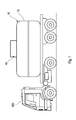
- FIG. 1 schematically shows a Erd Stammtank 10 according to an embodiment of the invention when transported by a road vehicle.
- the ground storage tank 10 can be transported with a normal truck 600 on the roads, ie not as a heavy load transport, so that a delivery of the Erd réelleanks 10 to residential buildings is possible without great effort.
- the Erd Profettidtank 10 has a capacity of conveniently at most 12,000 liters, preferably at most 10,000 liters, z. B. between about 4000 and about 7000 liters.
- Exemplary dimensions may be, for example, an outer diameter of about 2.5 m, a total height of, for example, 3.5 m with a volume of about 10 m 3 to 12 m 3 and an empty weight including heat exchanger devices of about 6 tons.
- the wall thickness can be for example 12 cm.
- the Erdtechnischtank 10 may be formed of concrete and, in the installed state, for. B. be designed as a stationary or horizontal cylinder.
- the wall thickness can be eg 8 mm.
- the ground storage tank 10 may be made of plastic as (in the installed state) standing cylinder.
- favorable dimensions can be length about 6.5 m, width about 2.5 m, height about 2.2 m, empty weight including heat exchanger devices about 12 tons, volume up to 38 m 3 .
- a prefabricated garage cover for a single garage or for a double garage can be adapted with simple means as a housing 12 of the Erd arrivedanks 10.
- the Erdtechnischtank 10 advantageously has in its housing 12, one or more openings 40 for a flow and return of at least one heat exchanger assembly, which is provided for installation in the interior of the housing 12.
- the ground storage tank 10 may be prefabricated with at least one heat exchanger assembly within the housing 12 or delivered empty.
- the ground storage tank 10 with at least one heat exchanger assembly within the housing 12 ready for connection pre-assembled, so that the installation on site is particularly inexpensive.
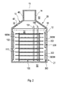
- FIG. 2 1 shows an exemplary embodiment of an underground storage tank 10 in a cutaway view with a favorable arrangement comprising a central first heat exchanger arrangement 100 and two outer heat exchanger arrangements 200 surrounding the first heat exchanger arrangement 100, 300.
- the level line 32 indicates a level height of a storage medium 30, for example, water in the interior of the housing 12 of the Erd Grandeanks 10 at.
- the first heat exchanger arrangement 100 comprises heat exchangers 100W, preferably in the form of pipe or hose windings.
- the heat exchangers 100W may be substantially single-layer or multi-layered and stacked in axially spaced-apart planes 110.
- the material of the heat exchanger 100W may be arbitrary, such as metal or plastic; Polyethylene (PE) is preferably used as inexpensive and durable material.
- the axially spaced-apart planes 110 can advantageously be flowed through in parallel from the heat transfer medium 102 in a fluidic manner via supply pipes 104, 106 (inlet and outlet) acting as distributors or collectors. All levels 110 can be flowed through at the same time.
- only a few selected ones of the planes 110 can be flowed through and further planes 110 can be switched on as needed in order to cover an increased cooling capacity, for example, if the ground storage tank 10 (also) is used for cooling.
- the heat exchangers 100W may preferably be wound in a U-shape as a double spiral per plane 110 on a spoke wheel-like mounting frame with the base of the double spiral centrally located and the two ends of the double spiral located on the outer circumference of the plane 110 and the spoke wheel-like mounting frame, respectively. are led to a valve or line connection outside the storage tank 10.
- the risk of an explosive effect on the housing 12 during freezing of the storage medium 30 can be reduced if the heat exchangers 100 W are wound in each plane 110 such that a lesser distance is set in an inner, central area between the substantially concentric windings than in one peripheral area of the levels 110. Neighboring Spiral arms are respectively flowed through in opposite directions of flow or rotation with the first heat transfer medium, which homogenizes the temperature in the storage medium 30.
- the planes 110 can be arranged analogously from bottom to top in increasing intervals.
- sufficient air space or a height range of storage medium 30 not intended for solidification can be provided so that the storage medium 30 can easily expand upon solidification.
- an overflow 42 is provided in the upper region 20 of the housing 12 above the filling level line 32.
- the housing 12 may be divided and dismountable with one or more mounting joints so as to be able to install individual or even a plurality of heat exchangers 100W in the housing 12 as prefabricated units.
- a removable cover 15 with a large area can be provided on the housing 12, which allows the heat exchanger 100W to be lowered into the housing.
- the second heat exchanger assembly 200 surrounds in this embodiment, the first heat exchanger assembly 100 in its axially upper region coaxial and z. B. at or near an inner side 18 of the housing 12 of the storage tank 10 is arranged.
- the second heat exchanger arrangement 200 consists of axially spaced tubes or hoses, in particular corrugated hoses, which serve as heat exchangers 200W and follow the contour of the inner side 18 of the housing 12. It is favorable to provide a gradient of the heat exchanger 200W between the feed 204 and the return 206 of the second heat exchanger arrangement 200 so that liquid condensing out in the heat transfer medium 202 can be collected and removed.
- a third heat exchanger assembly 300 is disposed which also surrounds the first heat exchanger assembly 100 concentrically with wound and axially spaced hoses or pipes serving as a heat exchanger 300W.
- the second heat exchanger assembly 200 may include, for example, a gaseous heat transfer medium 202.
- the diameters of the heat exchangers 200W typically do not have the same tube diameter or dimensions of the respective heat exchangers 200W as the heat exchanger assemblies 100, 300 operated with liquid heat transfer media 102, 302, but are larger than these.
- the heat exchanger 200W z. B. have a significantly larger diameter than the liquid-carrying heat exchanger 100W, 300W.
- the heat exchangers 300W are preferably in the form of one or more turns of pipe (conveniently gradient) extending along the inside of the housing 18 as a helical curve, as indicated in the figure is.
- the arrangement of the heat exchanger 300W at a distance from an inner wall is preferably such that the individual sections of the heat exchanger 300W have a slope in the same direction.
- a uniform gradient ensures that the simplest possible venting of the heat exchanger 300W during filling with the third heat transfer medium 302 is ensured.
- the second and third heat exchanger assemblies 200 and 300 are each preferably housed in the late or even freezing or solidifying zones of the storage medium 30 in the storage tank 10, but such that as little additional space is consumed. This results in a very compact storage tank 10.
- Each heat exchanger 200W, 300W second and / or third heat exchanger assembly 200 and 300 may be e.g. one or more turns, based on the inner circumference of the housing 12 have. However, individual or all heat exchangers 200W may also have more than one turn (e.g., 2 turns or 2.5 turns) or a fraction of one turn (e.g., 0.5 turns).
- a round or cylindrical housing 12 is also used in a mounting position with horizontal rather than vertical axis as a storage tank 10, wherein the individual heat exchanger assemblies 100, 200 and 300 are then positioned rotated in space accordingly.
- the housing 12 is made of plastic and two semi-cylindrical, larger basic shapes that form a horizontal Operaungsfuge in the mounted state, because then the empty upper half shell of the housing 12 from the top of the lower half-shell, with heat exchanger assemblies 100, 200 and 300 may already be pre-assembled, lowered with a lifting means and can be joined together to form a unit.
- the heat-transferring components of the heat exchanger arrangements 100, 200, 300 installed in the underground storage tank 10 are arranged below the filling level line 32 of the storage medium 30 or within the storage medium 30.
- the second and third heat exchanger assemblies 200 and 300 are located in a space region which is filled with liquid storage medium 30 in the ordinary case of operation.
- the total mass of the solidified storage medium 30 is thus as far as possible surrounded in the normal operating case by an expansion pressure protecting liquid portion 109, at least in the outer wall portion of the housing 12 and below the level line 32nd
- Connecting lines to the heat exchanger assemblies 100, 200, 300 may be routed to any location through one or more openings 40 in the ground storage tank 10. These are expediently arranged in such a way that the lowest possible heat or energy loss results and no thermal short circuits occur between adjacent system components. can be achieved by appropriate distances or insulation.
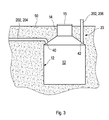
- FIG. 3 shows a side view of an exemplary embodiment of a Erd Grandeanks 10 in a mounting situation in the ground 50.
- the depth of the Erd Grandeanks 10 is low and located close to the ground.
- a cylindrical neck 14 is formed with a smaller diameter, which can be opened eg for maintenance and inspection purposes.
- the housing 12 may be formed as a hollow body of any cross-section, such as a hollow cylinder or a cuboid.
- a hollow body of any cross-section such as a hollow cylinder or a cuboid.
- Conceivable are quite other forms that will select the expert as needed.
- a cheap material for the housing is z. As stone, concrete or plastic. Since the storage tank 10 does not require a large minimum installation depth, the housing 12 may suitably so be designed that it is passable or accessible.
- the size of the housing 12 may be adapted to the respective needs. For this purpose, for larger diameters of the housing 12 for static reasons, a support strut may be arranged to z. B. to be able to carry a vehicle weight.
- the storage tank 10 may be formed in the manner of a rainwater cistern, e.g. poured in a concrete plant or made in a molding press made of plastic.
- Cross-section and shape of the Erd Mrsanks 10 can be chosen arbitrarily, just as needed, such as a cylinder, cuboid, sphere or the like.
- the Erdtechnischtank 10 can be ready for installation including heat exchanger assemblies 100, 200, 300 delivered to the installation site and there must be connected only to the appropriate supply lines for the various heat transfer media, conveyors, heat sources, consumers, etc.
- a type of connection is shown in which the flow 204 of the second heat exchanger device 200 is guided through an opening 40 a distance in the ground 50, while the return 206 is guided through another opening 42 upwards.
- other arrangements of flow 204 and return 206 may be provided, such as a central supply from above through the pipe 14th
- FIGS. 4a and 4b show by way of example and in simplified form other housing forms of a Erd Stammanks 10th
- FIG. 4a shows a cuboid housing 12 with lesser height than width
- FIG. 4b a substantially spherical housing 12 shows.
- the housing 12 may, as in FIG. 4a is indicated, be composed of two or more sub-shells 12a, 12b, such as an upper sub-shell 12a and a lower sub-shell 12b, which can be supplied as a closed housing 12.
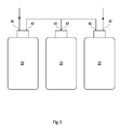
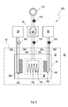
- FIG. 5 illustrates a series connection of supply and supply of at least one heat exchanger arrangement of three ground storage tanks 10 as an example of an increase of the available storage contents.
- more or less Erd Boulevardanks 10 may be provided, and the individual Erd réelleanks 10 may also be connected in parallel.
- Also conceivable is a mixture of parallel connection and series connection
- FIG. 6 schematically shows a schematic diagram of an advantageous embodiment of an energy storage system 500 with a Erd Proftank 10 used in the ground 50 with a first, second and third heat exchanger assembly 100, 200, 300, which are arranged in the housing of the Erd Stammtanks 10.
- An application of the portable Erd Itemss 10 in such an energy storage system 500 is particularly advantageous because here a relatively small storage volume is sufficient, for example, with water as a storage medium 30, for example, to economically provide a single-family house with heat energy.
- the size of the underground storage tank 10 is particularly designed to meet the energy needs of such an object.
- Heat is withdrawn by the first heat exchanger arrangement 100, expediently with a liquid heat transfer medium 102, while energy can be supplied virtually permanently to the ground storage tank 10 by the second heat exchanger arrangement 200, preferably by a gaseous heat transfer medium 202.
- the third heat exchanger arrangement 300 can also be used to supply heat. For example, with a liquid as the third heat transfer medium 302.
- the Erdtechnischtank 10 is at least temporarily with its environment, the soil 50 targeted in the heat exchange, i. At least temporarily, a heat flow from the soil 50 into the ground storage tank 10 (or from this into the ground 50) is desired for the operation of the ground storage tank 10.
- the reference numeral 52 is intended to indicate a system boundary in the soil 50 surrounding the earth storage tank 10 and relates to an area in the soil 50 which may still substantially introduce heat into the ground storage tank 10, i. a typical range of action between the environment of the underground storage tank 10 and the ground storage tank 10 itself, which typically depends on design parameters such as e.g.
- the soil 50 can serve as a source of geothermal energy and, on the other hand, deliver geothermal energy to the virtually uninsulated ground storage tank 10 during the usual withdrawal periods, for example heating periods.
- the surrounding soil 50 can at times even serve as an extension of the storage tank 10.
- the broken line indicates a typical area of action of the first heat exchanger assembly 100 which removes energy from the ground storage tank 10, e.g. B. for operating one or more heat pump 60, which raises the heat removed from the Erdtechnischtank 10 to a higher temperature level.
- the heat transfer medium 102 such as brine or a glycol-water mixture is circulated by a pump 120.
- the heat pump 60 converts the relatively low temperature level of the storage medium 30 of the underground storage tank 10 to a higher temperature level and supplies, e.g. via a pump 112, one or more heat consumers 114, such as a building to be heated.
- a conveyor 220 such as a fan, a blower, a circulation pump or the like, is temporarily in the flow 204 in the energy input arranged the second heat exchanger assembly 200, so that the waste heat of the conveyor 220 can be used with.
- a heat source 70 e.g. in the form of a heat supplying supply means 70 for a gaseous medium, e.g. Ambient air, exhaust gas, exhaust air or the like, connected to the heat input into the storage tank 10.
- a gaseous medium e.g. Ambient air, exhaust gas, exhaust air or the like
- flow 204 and / or the return 206 are partially relocated on the way to the Erd Grandeank 10 or away from the storage tank 10 over several meters in the ground 50 to additionally absorb geothermal heat.
- These areas of flow 204 and / or return 206 may also be switchable or be switched on and off by appropriate louvers or be bypassed by other lines.
- the third heat exchanger arrangement 300 serves for the regeneration of the storage medium and for the supply of heat and has a liquid heat transfer medium 302, e.g. Brine or a glycol-water mixture, which by means of a conveyor 320, e.g. a pump 320 is circulated.
- a liquid heat transfer medium 302 e.g. Brine or a glycol-water mixture
- the third heat exchanger assembly 300 is connected to the heat source 80 via a feed 304 and a return 306, wherein the pump 320 is conveniently located in the flow 304.
- the flow direction can be reversed in certain operating phases, so that supply 304 serves as a return and return 306 as a flow.
Abstract
Description
Die Erfindung betrifft einen Erdspeichertank für ein Energiespeichersystem nach dem Oberbegriff des Patentanspruchs 1.The invention relates to a ground storage tank for an energy storage system according to the preamble of patent claim 1.
Aus der
Dies wird unter anderem durch einen speziellen Erdspeichertank mit Wärmetauscherebenen erreicht, die bei Bedarf zu- oder abschaltbar sind. Durch einen Gradienten der Wärmetauscherschlangen in den Wärmetauscherebenen sowohl in radialer als auch in axialer Richtung sowie einer günstigen Anordnung von Zu- und Rücklauf der Wärmetauscherschlangen innerhalb der einzelnen und zwischen benachbarten Wärmetauscherebenen kann ein über das Speichervolumen sehr homogenes Laden und Entladen des Erdspeichertanks erfolgen. In einer Ausgestaltung ist der Erdspeichertank ein Eisspeicher, dessen Temperatur mit geringer Varianz um den Gefrierpunkt schwankt.This is achieved, among other things, by a special underground storage tank with heat exchanger levels, which can be switched on or off as required. By a gradient of the heat exchanger coils in the heat exchanger levels both in the radial and in the axial direction and a favorable arrangement of supply and return of the heat exchanger coils within the individual and between adjacent heat exchanger levels can be done on the storage volume very homogeneous loading and unloading of the Erdspeichertanks. In one embodiment, the underground storage tank is an ice storage whose temperature varies with low variance around the freezing point.
Aus der
Eine Aufgabe der Erfindung ist es, einen Erdspeichertank für ein Energiespeichersystem so weiterzuentwickeln, dass dieser für kleinere Einheiten wirtschaftlich ist.An object of the invention is to develop a ground storage tank for an energy storage system so that it is economical for smaller units.
Die Aufgabe wird durch die Merkmale des Patentanspruchs 1 gelöst.The object is solved by the features of patent claim 1.
Vorteilhafte Ausgestaltungen der Erfindung sind den weiteren Ansprüchen, der Zeichnung und der Beschreibung zu entnehmen.Advantageous embodiments of the invention are given in the further claims, the drawings and the description.
Es wird ein Erdspeichertank vorgeschlagen mit einem einen Innenraum umgebenden Gehäuse, wobei der Erdspeichertank zum Einbau ins Erdreich vorgesehen ist, und wobei der Innenraum zur Aufnahme eines Speichermediums und wenigstens einer ersten Wärmetauscheranordnung in Kontakt mit dem Speichermedium, vorgesehen ist, wobei der Erdspeichertank zum Transport, insbesondere zum Straßentransport, ausgebildet ist. Der Speichertank ist bereits zum Transport mit wenigstens einer Wärmetauscheranordnung innerhalb des Gehäuses vorkonfektioniert, wobei wenigstens eine zweite Wärmetauscheranordnung für ein zweites Wärmeträgermedium und/oder wenigstens eine dritte Wärmetauscheranordnung für ein drittes Wärmeträgermedium vorgesehen ist, wobei die erste Wärmetauscheranordnung von der zweiten und/oder dritten Wärmetauscheranordnung wenigstens bereichsweise umgeben ist.It is proposed a Erdspeichertank with a housing surrounding an interior, wherein the Erdspeichertank is provided for installation in the ground, and wherein the interior space for receiving a storage medium and at least a first heat exchanger assembly in contact with the storage medium, is provided, wherein the Erdspeichertank for transport, in particular for road transport. The storage tank is already prefabricated for transport with at least one heat exchanger assembly within the housing, wherein at least a second heat exchanger assembly for a second heat transfer medium and / or at least a third heat exchanger assembly is provided for a third heat transfer medium, wherein the first heat exchanger assembly of the second and / or third heat exchanger assembly is surrounded at least partially.
Die erste Wärmetauscheranordnung kann insbesondere zentral angeordnet sein und von der zweiten und dritten Wärmetauscheranordnung umgeben sein. Durch das Vorkonfektionieren mit den Wärmetauscheranordnungen kann der Erdspeichertank anschlussfertig angeliefert werden, was den Einbau für den Kunden weiter vereinfacht. Durch die Ausbildung des Erdspeichertanks zum schwerlastfreien Straßentransport, d.h. zum Transport ohne Schwerlasttransporter, kann der Speichertank auf der Ladefläche eines üblichen Lastkraftwagens transportiert werden. Der Vorteil ist, dass die Notwendigkeit entfällt, den Speichertank erst am Einbauort zu fertigen. Übliche Erdspeichertanks werden vor Ort gefertigt, und müssen z.B. aus Beton gegossen werden. Dies bedeutet einen hohen Aufwand für den Aufbau eines Energiespeichersystems mit einem solchen Erdspeichertank, da nicht nur der Aushub für den Erdspeichertank gemacht werden muss, sondern auch die Infrastruktur für das Gießen des Betongehäuses vor Ort gebracht und der Beton gegossen werden muss und dieser auch aushärten muss. Dies ist einerseits zeitaufwändig und kann andererseits nur bei Außentemperaturen durchgeführt werden, bei denen ein Aushärten des Betons möglich ist, da sonst Schäden am Gehäuse drohen. Ein Kunde kann den erfindungsgemäßen Erdspeichertank einfach beim Händler in Augenschein nehmen und eine geeignete Form und Größe auswählen und anliefern lassen, womit der Aufwand reduziert und die Wetterabhängigkeit des Einbaus des Erdspeichertanks deutlich verringert werden kann. Wird eine größere Speichermenge gewünscht, können zwei oder mehr Erdspeichertanks zusammengeschaltet werden, womit sich ein flexibles Speichervolumen ergibt, das sich bedarfsabhängig vergrößern oder verkleinern lässt. Ein günstiges Fassungsvermögen des Gehäuses des Erdspeichertanks liegt bei unter 10000 Litern, z.B. zwischen 3000 und 7000 Litern, was sich problemlos von Gewicht und Größe her mit einem gängigen Lastkraftwagen transportieren lässt. Das Gehäuse kann einteilig sein oder aus zwei oder mehr Schalen gefertigt sein, die vor Ort zusammengefügt werden.The first heat exchanger arrangement can in particular be arranged centrally and surrounded by the second and third heat exchanger arrangement. By prefabricating with the heat exchanger assemblies, the Erdspeicherank be delivered ready for connection, which further simplifies installation for the customer. Due to the design of the underground storage tank for heavy-load road transport, ie for transport without heavy goods vehicles, the storage tank can be transported on the back of a conventional truck. The advantage is that there is no need to manufacture the storage tank at the installation site. Usual underground storage tanks are made on site, and must be cast from concrete, for example. This means a lot of effort for the construction of an energy storage system with such a Erdspeichertank, since not only the excavation for the Erdspeichertank must be made, but also brought the infrastructure for the casting of the concrete housing on site and the concrete must be poured and this must also harden , On the one hand, this is time-consuming and, on the other hand, can only be carried out at outside temperatures at which hardening of the concrete is possible, since otherwise damage to the housing is imminent. A customer can simply inspect the earth storage tank according to the invention at the dealer and select and deliver a suitable shape and size, whereby the effort can be reduced and the weather dependence of the installation of the Erdspeicheranks can be significantly reduced. If a larger amount of storage is desired, two or more underground storage tanks can be interconnected, resulting in a flexible storage volume that can be increased or decreased as needed. A favorable capacity of the housing of the underground storage tank is less than 10000 liters, eg between 3000 and 7000 liters, which can be easily transported by weight and size with a standard truck. The housing may be in one piece or made from two or more shells that are assembled on site.
Die skalierbare Größe und weitgehend variable Formgestaltung des Erdspeichertanks macht es günstigerweise möglich, den Erdspeichertank z. B. im Vorgarten eines Einfamilienhauses zu vergraben, ohne dass die darüber liegen Flächen als Nutzfläche verloren gehen oder dass die Optik der Umgebung dadurch beeinträchtigt würde. Auch können z. B. Garagen oberhalb des Erdspeichertanks errichtet werden, so dass durch den Erdspeichertank keine Fläche verloren geht. Der Erdspeichertank kann bei entsprechender Formgebung und Stabilität gleichzeitig auch als Fundament oder Untergrund für eine Garage oder ein anderes Bauwerk genutzt werden.The scalable size and largely variable shape of the Erdspeicheranks makes it conveniently possible, the Erdspeicherank z. B. to bury in the front yard of a family house, without that over it Loss of area as useful area or that the appearance of the environment would be affected. Also z. As garages are built above the Erdspeichertanks so that no area is lost by the Erdspeichertank. The Erdspeichertank can be used with appropriate shape and stability at the same time as a foundation or substrate for a garage or other structure.
Bevorzugt ist der Erdspeichertank zur Aufnahme eines Speichermediums vorgesehen, das unter Freisetzung oder Aufnahme latenter Wärme seinen Aggregatzustand ändert, beispielsweise zwischen flüssig und fest. Günstigerweise ist als Speichermedium Wasser vorgesehen. Denkbar sind jedoch auch andere Materialien denkbar, z.B. Paraffin, je nach gewünschtem Temperaturniveau des Speichermediums. Der Erdspeichertank kann gegebenenfalls beim Transport mit dem Speichermedium befüllt sein.Preferably, the Erdspeichertank is provided for receiving a storage medium, which changes its state of aggregation, releasing or absorbing latent heat, for example, between liquid and solid. Conveniently, water is provided as the storage medium. However, other materials are also conceivable, e.g. Paraffin, depending on the desired temperature level of the storage medium. The Erdspeichertank may optionally be filled during transport with the storage medium.
Der Erdspeichertank kann bestimmungsgemäß mit seiner Umgebung wenigstens zeitweise bestimmungsgemäß in Wärmetausch stehen, so dass Umgebungswärme aus dem Erdreich genutzt werden kann oder die nähere Speicherumgebung als Erweiterung des Erdspeichertanks genutzt werden kann. Der Ausdruck ,,bestimmungsgemäß mit seiner Umgebung in Wärmetausch stehend" soll bedeuten, dass der Erdspeichertank für seine reguläre Funktion zumindest zeitweise in Wärmetausch mit seiner Umgebung steht, d.h. nicht oder zumindest zeitweise nicht gegen den Wärmetausch isoliert ist. Dies trifft auf einen erdunterstützten Speichertank zu, der im Erdreich vergraben ist und gezielt z.B. Wärme aus dem umgebenden Erdreich aufnimmt.The Erdspeichertank can be intended in heat exchange with its environment at least temporarily intended so that ambient heat from the soil can be used or the closer storage environment can be used as an extension of the Erdspeichertanks. The term "heat exchanged with its environment as intended" is intended to mean that the underground storage tank is at least temporarily in heat exchange with its environment for its regular function, ie is not or at least temporarily isolated from heat exchange, which applies to an earth-based storage tank which is buried in the ground and specifically absorbs, for example, heat from the surrounding soil.
Vorteilhaft kann das Gehäuse in der Art einer Regenwasserzisterne ausgebildet sein, wobei das Gehäuse insbesondere ein Fassungsvermögen von höchstens 12 m3 aufweisen kann. Günstig für den Straßentransport ist, wenn das Gehäuse einen Außendurchmesser von höchstens 2,5 m aufweisen kann. Mit dieser Ausgestaltung wird eine sinnvolle Größe eines Speichertanks zur Verfügung gestellt, der für eine ökonomische Energieversorgung durch ein entsprechendes, wenigstens einen erfindungsgemäßen Erdspeichertank umfassendes Energieversorgungssystem insbesondere eines Einfamilienhauses geeignet ist.Advantageously, the housing may be designed in the manner of a rainwater cistern, wherein the housing may in particular have a capacity of at most 12 m 3 . Convenient for road transport, if the housing can have an outer diameter of at most 2.5 m. With this Embodiment is provided a meaningful size of a storage tank, which is suitable for an economic energy supply by a corresponding, at least one Erdspeicherank comprehensive energy supply system in particular a single-family house.
Alternativ kann der Erdspeichertank ein Gehäuse aufweisen, das in der Art einer Fertiggaragenhülle ausgebildet sein kann, wobei das Gehäuse insbesondere ein Fassungsvermögen von höchstens 38 m3 aufweisen kann. Günstig für den Straßentransport ist, wenn das Gehäuse eine Länge von etwa 6,5 m, eine Breite von etwa 2,5 m und eine Höhe von etwa 2,2 m aufweisen kann. Mit dieser Ausgestaltung wird eine sinnvolle Größe eines Speichertanks zur Verfügung gestellt, der für eine ökonomische Energieversorgung durch ein entsprechendes, wenigstens einen erfindungsgemäßen Erdspeichertank umfassendes Energieversorgungssystem insbesondere eines Einfamilienhauses geeignet ist.Alternatively, the Erdspeichertank may have a housing which may be formed in the manner of a prefabricated garage shell, wherein the housing may in particular have a capacity of at most 38 m 3 . Convenient for road transport is when the housing may have a length of about 6.5 m, a width of about 2.5 m and a height of about 2.2 m. With this embodiment, a meaningful size of a storage tank is provided, which is suitable for an economic energy supply by a corresponding, at least one Erdspeicherank comprehensive energy supply system in particular a single-family house.
Je nach Energiebedarf und Größe des zu versorgenden Objekts wird der Fachmann eine geeignete Größe des Erdspeichertanks auswählen.Depending on the energy requirement and the size of the object to be supplied, the skilled person will select a suitable size of the underground storage tank.
Gemäß einer günstigen Weiterbildung kann das Gehäuse wenigstens eine Öffnung zur Durchführung eines Vorlaufs und eines Rücklaufs für wenigstens ein Wärmeträgermedium wenigstens einer Wärmetauscheranordnung aufweisen. So können ohne großen Aufwand wenigstens eine Wärmetauscheranordnung im Gehäuse angeordnet sein oder am Einbauort eingebaut werden und an ein Energiespeichersystem, insbesondere an Fördermittel für Wärmeträgermedium, Wärmequellen und Verbraucher, angeschlossen werden.According to a favorable development, the housing can have at least one opening for carrying out a flow and a return for at least one heat transfer medium of at least one heat exchanger arrangement. Thus, at least one heat exchanger arrangement can be arranged in the housing without great effort or be installed at the installation site and connected to an energy storage system, in particular to conveyance for heat transfer medium, heat sources and consumers.
Vorteilhaft kann der Erdspeichertank in der Art einer Regenwasserzisterne ausgebildet sein, die zum Beispiel in einem Betonwerk gegossen oder mit einer Kunststoffschale gefertigt wird, oder auch in der Art und Form einer Fertiggarage aus Beton. Der Erdspeichertank kann einem Anwender einbaufertig geliefert werden und muss dort lediglich mit den entsprechenden Anschlüssen für die verschiedenen Wärmeträgermedien verbunden werden. Besonders vorteilhaft ist eine Verwendung einer Regenwasserzisterne und/oder einer Fertiggaragenhülle für einen Erdspeichertank. Die Bauteile müssen lediglich mit entsprechenden Anschlussmöglichkeiten und Abdichtungen für Zulauf und Rücklauf sowie mit Haltemitteln für ein oder mehrere Wärmetauschereinrichtungen versehen werden, was sich technisch leicht umsetzen lässt.Advantageously, the Erdspeichertank be formed in the manner of a rainwater cistern, which is cast for example in a concrete plant or made with a plastic shell, or in the form and shape of a prefabricated garage of concrete. The underground storage tank can be delivered ready for installation to a user be and must be connected there only with the appropriate connections for the various heat transfer media. Particularly advantageous is a use of a rainwater cistern and / or a prefabricated garage shell for a Erdspeichertank. The components need only be provided with appropriate connection options and seals for inlet and return and with holding means for one or more heat exchanger devices, which can be technically easily implemented.
In einer weiteren Ausgestaltung kann die erste Wärmetauscheranordnung axial übereinander angeordnete Ebenen von konzentrisch gewundenen Wärmeübertragern umfassen. Die Wärmeübertrager können z.B. Rohre oder Schläuche sein. Damit lässt sich im Betrieb eine günstige und homogene Betriebsweise des Erdspeichertanks erreichen.In a further embodiment, the first heat exchanger arrangement may comprise axially superimposed planes of concentrically wound heat exchangers. The heat exchangers may e.g. Be pipes or hoses. This can be achieved in operation a favorable and homogeneous operation of the underground storage tank.
Vorzugsweise ist die erste Wärmetauscheranordnung dafür vorgesehen, dem Speichertank in einer Entzugsperiode Wärme zu entziehen. Die entzogene Wärme kann z. B. zum Heizen und/oder zur Warmwasserbereitung verwendet werden. Dazu kann das Temperaturniveau des die entzogene Wärme transportierenden ersten Wärmeträgermediums mit einer an die erste Wärmetauscheranordnung angeschlossenen Wärmepumpe entsprechend angehoben werden. Das erste Wärmeträgermedium kann vorzugsweise flüssig, z.B. Sole oder ein Wasser-Glykol-Gemisch sein.Preferably, the first heat exchanger arrangement is intended to extract heat from the storage tank in a withdrawal period. The extracted heat can z. B. are used for heating and / or water heating. For this purpose, the temperature level of the first heat transfer medium transporting the extracted heat can be correspondingly raised with a heat pump connected to the first heat exchanger arrangement. The first heat transfer medium may preferably be liquid, e.g. Brine or a water-glycol mixture.
Zweckmäßigerweise ist die erste Wärmetauscheranordnung so in dem Gehäuse angeordnet, dass ein kontrolliertes Erstarren und Auftauen des Speichermediums erfolgen kann, das eine Spreng- oder Druckwirkung auf das Gehäuse des Speichertanks vermindert. Sinnvollerweise kann das Gehäuse alternativ oder zusätzlich einen Pufferbereich aufweisen, der einen Volumenzuwachs des Speichermediums aufnehmen kann.Conveniently, the first heat exchanger assembly is arranged in the housing, that a controlled solidification and thawing of the storage medium can take place, which reduces a blasting or pressure effect on the housing of the storage tank. The housing can usefully, alternatively or additionally, have a buffer area which can accommodate a volume increase of the storage medium.
Mit der zweiten und/oder dritten Wärmetauscheranordnung kann beispielsweise das Speichermedium regeneriert werden, wenn dieses thermisch entladen ist und ansonsten Wärmeenergie dem Speichermedium zugeführt und im Erdspeichertank gespeichert werden, während die erste Wärmetauscheranordnung ganz oder zumindest überwiegend zum Wärmeentzug vorgesehen ist. Die zweite und/oder dritte Wärmetauscheranordnung kann verhindern, dass erstarrendes Speichermedium an das Gehäuse gelangt oder dieses zumindest verzögern. Gegebenenfalls kann die zweite und/oder dritte Wärmetauscheranordnung aus mehreren separaten Wärmetauscheranordnungen bestehen, die z.B. an unterschiedlichen Positionen im Speichertank angeordnet sein können.With the second and / or third heat exchanger arrangement, for example, the storage medium can be regenerated when it is thermally discharged and heat energy otherwise supplied to the storage medium and stored in the Erdspeichertank, while the first heat exchanger assembly is provided entirely or at least predominantly for heat removal. The second and / or third heat exchanger arrangement can prevent solidifying storage medium from reaching the housing or at least delaying it. Optionally, the second and / or third heat exchanger assembly may consist of several separate heat exchanger assemblies, e.g. can be arranged at different positions in the storage tank.
Vorteilhaft kann die zweite Wärmetauscheranordnung gemäß einer weiteren Ausgestaltung eine Auffangvorrichtung für Kondensat aufweisen. Dies ist besonders zweckmäßig, wenn als zweites Wärmeträgermedium ein Gas, z.B. Luft, eingesetzt wird. Feuchte Luft bringt einen zusätzlichen Energieeintrag über die Kondenswärme des Wassergehalts in der Luft.Advantageously, the second heat exchanger arrangement according to another embodiment have a collecting device for condensate. This is particularly useful if, as the second heat transfer medium, a gas, e.g. Air, is used. Moist air brings an additional energy input via the condensed heat of the water content in the air.
In einer weiteren Ausgestaltung kann in einem Vorlauf der zweiten Wärmetauscheranordnung eine Kopplungseinrichtung für eine Fördereinrichtung vorgesehen sein. Mit der Fördereinrichtung kann ein Gas, z.B. Luft in die Wärmetauscheranordnung eingepresst werden und die Abwärme der Fördereinrichtung mit eingebracht werden.In a further embodiment, a coupling device for a conveyor device can be provided in a supply line of the second heat exchanger arrangement. With the conveyor, a gas, e.g. Air are pressed into the heat exchanger assembly and the waste heat of the conveyor to be introduced.
Vorteilhaft kann die zweite und/oder dritte Wärmetauscheranordnung wenigstens bereichsweise an einer Innenseite des Gehäuses angeordnet sein. Ein Vorteil der Anordnung an der Innenseite des Gehäuses besteht darin, dass das erstarrende Speichermedium nicht an die Gehäusewand gelangt. Vorzugsweise kann die zweite und/oder dritte Wärmetauschereinrichtung wenigstens bereichsweise die erste Wärmetauscheranordnung umgeben, wodurch das Speichermedium nahe der Gehäusewand länger flüssig bleiben kann.Advantageously, the second and / or third heat exchanger arrangement can be arranged at least in regions on an inner side of the housing. An advantage of the arrangement on the inside of the housing is that the solidifying storage medium does not reach the housing wall. Preferably, the second and / or third heat exchanger device at least partially the surrounded first heat exchanger assembly, whereby the storage medium near the housing wall can remain liquid longer.
Denkbar ist weiterhin, die zweite und/oder dritte Wärmetauscheranordnung wenigstens bereichsweise innerhalb der Gehäusewand anzuordnen. Die Wärmetauscheranordnung kann in diesem Fall bei der Herstellung des Gehäuses einfach mit eingegossen werden. Zweckmäßigerweise kann die zweite Wärmetauscheranordnung die erste Wärmetauscheranordnung wenigstens bereichsweise umgeben.It is also conceivable to arrange the second and / or third heat exchanger arrangement at least in regions within the housing wall. The heat exchanger assembly can be easily molded in this case in the manufacture of the housing. Advantageously, the second heat exchanger arrangement can surround the first heat exchanger arrangement at least in regions.
In einer günstigen Ausgestaltung können Wärmeübertrager der zweiten und/oder dritten Wärmetauscheranordnung sich wenigstens bereichsweise in Umfangsrichtung des Gehäuses erstrecken. Die Wärmeübertrager können Schläuche oder Rohre sein, welche dazu vorgesehen sind, das jeweilige Wärmeträgermedium führen, und können wenigstens eine Strecke entlang der Innenwand geführt sein, oder diese auch in einer Schleife ganz oder auch mehrfach umrunden. Die Ausgestaltung der Wärmeübertrager und deren Verlegung im Gehäuse kann bedarfsgerecht von einem Fachmann ausgewählt werden und an das konkrete Energiespeichersystem und die verfügbaren Wärmequellen und Verbraucher und die am Einsatzort herrschenden Randbedingungen angepasst werden.In a favorable embodiment, heat exchangers of the second and / or third heat exchanger arrangement can extend at least partially in the circumferential direction of the housing. The heat exchangers may be hoses or pipes, which are provided to guide the respective heat transfer medium, and may be guided at least a distance along the inner wall, or circumnavigate it in a loop completely or even several times. The design of the heat exchanger and their installation in the housing can be selected as needed by a professional and adapted to the specific energy storage system and the available heat sources and consumers and the conditions prevailing at the site boundary conditions.
In einer zweckmäßigen Ausgestaltung kann das Gehäuse wenigstens eine Einrichtung zum Befestigen einer Transportsicherung aufweisen, was den Transport des Erdspeichertanks sowie das Auf- und Abladen erleichtert.In an expedient embodiment, the housing may have at least one device for securing a transport lock, which facilitates the transport of the underground storage tank and the loading and unloading.
Im Speichertank des Energiespeichersystems können unterschiedliche intervallartig anfallende Energieformen verfügbar gemacht und effektiv z.B. zum Heizen genutzt werden, was insbesondere in Verbindung mit Wärmepumpen für Heizungsanlagen vorteilhaft ist. Die Funktion als Energiespeichersystem beinhaltet, dass alle eingespeisten günstigen Wärmemengen entweder sofort oder auch erst später, je nach Bedarf, entnommen werden können.In the storage tank of the energy storage system different forms of energy accumulating intervals can be made available and effectively used, for example, for heating, which is particularly advantageous in connection with heat pumps for heating systems. The function as an energy storage system includes that all injected low heat quantities can be removed either immediately or later, as needed.
Weitere Vorteile ergeben sich aus der folgenden Zeichnungsbeschreibung. In der Zeichnung sind Ausführungsbeispiele der Erfindung dargestellt. Die Zeichnung, die Beschreibung und die Ansprüche enthalten zahlreiche Merkmale in Kombination. Der Fachmann wird die Merkmale zweckmäßigerweise auch einzeln betrachten und zu sinnvollen weiteren Kombinationen zusammenfassen.Further advantages emerge from the following description of the drawing. In the drawings, embodiments of the invention are shown. The drawing, the description and the claims contain numerous features in combination. The person skilled in the art will expediently also consider the features individually and combine them into meaningful further combinations.
Es zeigen in schematischer Darstellung:
- Figur 1
- schematisch einen Speichertank nach einer Ausgestaltung der Erfindung beim Transport;
- Figur 2
- eine Ausgestaltung eines Speichertanks in aufgeschnittener Darstellung mit einer günstigen Anordnung mit einer zentralen ersten Wärmetauscheranordnung und zwei äußeren, die erste Wärmetauscheranordnung umgebende Wärmetauscheranordnungen;
- Figur 3
- in einer Seitenansicht ein Ausführungsbeispiel eines im Erdreich vergrabenen, erdreichgestützten Speichertanks;
- Figur 4a, 4b
- in einer Seitenansicht weitere Ausführungsbeispiele von erdreichgestützten Speichertanks in Quaderform zusammengesetzt aus einer oberen und unteren Schale (
Fig. 4a ) und in Kugelform (Fig. 4b ) - Figur 5
- eine Anordnung von mehreren zusammengeschalteten Speichertanks; und
- Figur 6
- einen Prinzipschaltplan einer Ausgestaltung eines erfindungsgemäßen Energiespeichersystems mit einem Speichertank und drei Wärmetauscheranordnungen;
- FIG. 1
- schematically a storage tank according to an embodiment of the invention during transport;
- FIG. 2
- an embodiment of a storage tank in a cutaway view with a favorable arrangement with a central first heat exchanger assembly and two outer, the first heat exchanger assembly surrounding heat exchanger assemblies;
- FIG. 3
- in a side view an embodiment of a buried in the ground, earthquake-based storage tank;
- Figure 4a, 4b
- in a side view of further embodiments of earth-based storage tanks in cuboid shape composed of an upper and lower shell (
Fig. 4a ) and in spherical form (Fig. 4b ) - FIG. 5
- an array of multiple interconnected storage tanks; and
- FIG. 6
- a schematic diagram of an embodiment of an energy storage system according to the invention with a storage tank and three heat exchanger assemblies;
Im Wesentlichen gleich bleibende Teile sind in den Figuren grundsätzlich mit den gleichen Bezugszeichen beziffert.Essentially identical parts are numbered in the figures basically with the same reference numerals.
Dazu kann günstigerweise vorgesehen sein, dass der Erdspeichertank 10 ein Fassungsvermögen von günstigerweise höchstens 12000 Litern, vorzugsweise höchstens 10000 Litern, z. B. zwischen etwa 4000 und etwa 7000 Litern.For this purpose, it can be conveniently provided that the
Beispielhafte Abmessungen können z.B. ein Außendurchmesser von etwa 2,5 m, eine Gesamthöhe von z.B. 3,5 m mit einem Volumen von etwa 10 m3 bis 12 m3 und einem Leergewicht inklusive Wärmetauschereinrichtungen von etwa 6 Tonnen sein. Die Wandstärke kann beispielsweise 12 cm betragen. Der Erdspeichertank 10 kann aus Beton gebildet sein und, im Einbauzustand, z. B. als stehender oder liegender Zylinder ausgeführt sein.Exemplary dimensions may be, for example, an outer diameter of about 2.5 m, a total height of, for example, 3.5 m with a volume of about 10 m 3 to 12 m 3 and an empty weight including heat exchanger devices of about 6 tons. The wall thickness can be for example 12 cm. The
In einer kleineren Variante können beispielhafte Abmessungen sein: Außendurchmesser von etwa 2 m, Länge z.B. 2,5 m, Volumen von etwa 6,5 m3 und Leergewicht, inklusive Wärmetauschereinrichtungen von etwa 400 kg, unter 6 Tonnen. Die Wandstärke kann z.B. 8 mm sein. Der Erdspeichertank 10 kann aus Kunststoff als (im Einbauzustand) stehender Zylinder ausgeführt sein.In a smaller variant may be exemplary dimensions: outer diameter of about 2 m, length for example 2.5 m, volume of about 6.5 m 3 and curb weight, including heat exchanger facilities of about 400 kg, under 6 tons. The wall thickness can be eg 8 mm. The
In einer weiteren Variante in Form eines rechteckigen Gehäuses aus Beton, insbesondere in der Art einer Fertiggaragenhülle, können günstige Abmessungen sein Länge ca. 6,5 m, Breite ca. 2,5 m, Höhe ca. 2,2 m, Leergewicht inklusive Wärmetauschereinrichtungen etwa 12 Tonnen, Volumen bis zu 38 m3.In a further variant in the form of a rectangular housing made of concrete, in particular in the form of a prefabricated garage shell, favorable dimensions can be length about 6.5 m, width about 2.5 m, height about 2.2 m, empty weight including heat exchanger devices about 12 tons, volume up to 38 m 3 .
Eine Fertiggaragenhülle für eine Einzelgarage oder für eine Doppelgarage lässt sich mit einfachen Mitteln als Gehäuse 12 des Erdspeichertanks 10 anpassen.A prefabricated garage cover for a single garage or for a double garage can be adapted with simple means as a
Die genannten Parameter und Materialien sind lediglich als illustrative Beispiele gedacht. Andere Abmessungen und Ausführungen sind selbstverständlich möglich.The mentioned parameters and materials are intended as illustrative examples only. Other dimensions and designs are of course possible.
Der Erdspeichertank 10 weist vorteilhaft in seinem Gehäuse 12 eine oder mehrere Öffnungen 40 für einen Vorlauf und Rücklauf wenigstens einer Wärmetauscheranordnung auf, die zum Einbau in das Innere des Gehäuses 12 vorgesehen ist. Der Erdspeichertank 10 kann mit wenigstens einer Wärmetauscheranordnung innerhalb des Gehäuses 12 vorkonfektioniert sein oder leer angeliefert werden. Mit Vorteil ist der Erdspeichertank 10 mit wenigstens einer Wärmetauscheranordnung innerhalb des Gehäuses 12 anschlussfertig vorkonfektioniert, so dass der Einbau vor Ort besonders unaufwändig ist.The
Die erste Wärmetauscheranordnung 100 umfasst Wärmeübertrager 100W, vorzugsweise in Form von Rohr- oder Schlauchwicklungen. Die Wärmeübertrager 100W können im Wesentlichen einlagig oder auch mehrlagig ausgebildet und in axial voneinander beabstandeten Ebenen 110 übereinander gestapelt. Das Material der Wärmeübertrager 100W kann beliebig sein, etwa Metall oder Kunststoff; als preiswertes und dauerhaftes Material wird bevorzugt Polyethylen (PE) eingesetzt. Die axial beabstandeten Ebenen 110 können vorteilhaft über als Verteiler oder Sammler wirkende Versorgungsrohre 104, 106 (Zulauf und Ablauf) strömungstechnisch parallel vom Wärmeträgermedium 102 durchströmbar sein. Dabei können alle Ebenen 110 gleichzeitig durchströmt werden. Optional können auch nur einige ausgewählte der Ebenen 110 durchströmt werden und bedarfsweise weitere Ebenen 110 zugeschaltet werden, um etwa eine erhöhte Kühlleistung abzudecken, falls der Erdspeichertank 10 (auch) zur Kühlung eingesetzt wird.The first
Die Wärmeübertrager 100W können vorzugsweise U-förmig als Doppelspirale pro Ebene 110 auf einem speichenradähnlichen Montagegestell aufgewickelt sein, wobei die Basis der Doppelspirale zentral angeordnet ist und die beiden Enden der Doppelspirale sich am äußeren Umfang der Ebene 110 bzw. dem speichenradähnlichen Montagegestell befinden und z.B. zu einem Ventil oder Leitungsanschluss außerhalb des Speichertanks 10 geführt sind.The
Die Gefahr einer Sprengwirkung auf das Gehäuse 12 beim Einfrieren des Speichermediums 30 kann reduziert werden, wenn die Wärmeübertrager 100W in jeder Ebene 110 so gewickelt sind, dass in einem inneren, zentralen Bereich ein geringerer Abstand eingestellt ist zwischen den im Wesentlichen konzentrischen Wicklungen als in einem umfangsnahen Bereich der Ebenen 110. Benachbarte Spiralarme werden jeweils in entgegengesetzten Fließ- bzw. Drehrichtungen mit dem ersten Wärmeträgermedium durchströmt, was die Temperatur im Speichermedium 30 homogenisiert. Vorteilhafterweise können die Ebenen 110 analog von unten nach oben in größer werdenden Abständen angeordnet sein. Zusätzlich kann über der obersten Ebene 110 ein ausreichender Luftraum oder ein nicht zur Erstarrung vorgesehener Höhenbereich von Speichermedium 30 vorgesehen sein, damit sich das Speichermedium 30 beim Erstarren problemlos ausdehnen kann. Ferner ist ein Überlauf 42 im oberen Bereich 20 des Gehäuses 12 oberhalb der Füllstandslinie 32 vorgesehen.The risk of an explosive effect on the
Das Gehäuse 12 kann mit einer oder mehreren Montagefugen geteilt und zerlegbar sein, um einzelne oder auch gleich mehrere Wärmeübertrager 100W in das Gehäuse 12 als vorgefertigte Einheiten einbauen zu können. Alternativ kann zum Einbau der vorgefertigten Wärmeübertrager 100W auch ein abnehmbarer Deckel 15 mit großer Fläche auf dem Gehäuse 12 vorgesehen sein, der ein Absenken der Wärmeübertrager 100W in das Gehäuse gestattet.The
Die zweite Wärmetauscheranordnung 200 umgibt in diesem Ausführungsbeispiel die erste Wärmetauscheranordnung 100 in ihrem axial oberen Bereich koaxial und ist z. B. an oder nahe einer Innenseite 18 des Gehäuses 12 des Speichertanks 10 angeordnet. Die zweite Wärmetauscheranordnung 200 besteht aus axial beabstandeten Rohren oder Schläuchen, insbesondere Wellschläuchen, die als Wärmeübertrager 200W dienen und der Kontur der Innenseite 18 des Gehäuses 12 folgen. Günstig ist, ein Gefälle der Wärmeübertrager 200W zwischen Vorlauf 204 und Rücklauf 206 zweiten Wärmetauscheranordnung 200 vorzusehen, damit im Wärmeträgermedium 202 auskondensierende Flüssigkeit gesammelt und abgeführt werden kann.The second
Im gezeigten Ausführungsbeispiel axial unterhalb der zweiten Wärmetauscheranordnung 200 ist in einem unteren Bereich 21 des Speichertanks 10 eine dritte Wärmetauscheranordnung 300 angeordnet, welche ebenfalls die erste Wärmetauscheranordnung 100 konzentrisch mit als Wärmeübertrager 300W dienenden gewundenen und axial beabstandeten Schläuchen oder Rohren umgibt.In the exemplary embodiment shown, axially below the second
Die zweite Wärmetauscheranordnung 200 kann beispielsweise ein gasförmiges Wärmeträgermedium 202 beinhalten. Die Durchmesser der Wärmeübertrager 200W weisen typischerweise nicht den gleichen Rohrdurchmesser oder die gleichen Abmessungen der jeweiligen Wärmeübertrager 200W auf wie die mit flüssigem Wärmeträgermedien 102, 302 betriebenen Wärmetauscheranordnungen 100, 300, sondern sind größer als diese. Typischerweise können die Wärmeübertrager 200W z. B. einen deutlich größeren Durchmesser als die Flüssigkeit führenden Wärmeübertrager 100W, 300W aufweisen.The second
Bei Gehäusen 12 mit kreisrundem Grundriss, etwa in der Art einer üblichen Regenwasserzisterne, sind die Wärmeübertrager 300W vorzugsweise in Form einer oder mehrerer Rohrwindungen (günstigerweise mit Gefälle) ausgeführt, die nahe der Innenseite 18 des Gehäuses entlang als Schraubenkurve verlaufen, wie in der Figur angedeutet ist. Bei Gehäusen 12 mit eckigem Querschnitt, etwa in der Art einer Fertiggaragenhülle, ist die Anordnung der Wärmeübertrager 300W im Abstand zu einer Innenwand vorzugsweise so, dass die einzelnen Abschnitte der Wärmeübertrager 300W ein Gefälle in die gleiche Richtung aufweisen. Ein gleichmäßiges Gefälle stellt sicher, dass eine möglichst einfache Entlüftung des Wärmeübertragers 300W beim Befüllen mit dem dritten Wärmeträgermedium 302 gewährleistet ist.In
Die zweite und dritte Wärmetauscheranordnung 200 und 300 ist jeweils vorzugsweise in den spät oder gar nicht vereisenden bzw. erstarrenden Zonen des Speichermediums 30 im Speichertank 10 untergebracht, jedoch so, dass möglichst wenig zusätzlicher Platz dafür verbraucht wird. Damit ergibt sich ein sehr kompakter Speichertank 10.The second and third
Jeder Wärmeübertrager 200W, 300W zweiten und/oder dritten Wärmetauscheranordnung 200 und 300 kann z.B. eine oder mehrere Windung, bezogen auf den inneren Umfang des Gehäuses 12 aufweisen. Einzelne oder alle Wärmeübertrager 200W können aber auch mehr als eine Windung aufweisen (z.B. 2 Windungen oder 2,5 Windungen) oder einen Bruchteil von einer Windung (z.B. 0,5 Windungen).Each
Grundsätzlich ist es denkbar (zeichnerisch nicht dargestellt), dass ein rundes oder zylindrisches Gehäuse 12 auch in einer Einbaulage mit liegender statt vertikaler Achse als Speichertank 10 verwendet wird, wobei die einzelnen Wärmetauscheranordnungen 100, 200 und 300 dann entsprechend im Raum gedreht positioniert sind. Dies ist dann sinnvoll, wenn das Gehäuse 12 aus Kunststoff und aus zwei halbzylinderähnlichen, größeren Grundformen besteht, die im montierten Zustand eine horizontale Teilungsfuge bilden, weil dann die leere obere Halbschale des Gehäuses 12 von oben auf die untere Halbschale, die mit Wärmetauscheranordnungen 100, 200 und 300 schon vormontiert sein kann, mit einem Hebemittel herabgelassen und mit ihr zu einer Einheit zusammengefügt werden kann.In principle, it is conceivable (not shown in the drawing) that a round or
Die in den Erdspeichertank 10 eingebauten wärmeübertragenden Bauelemente der Wärmetauscheranordnungen 100, 200, 300 sind unterhalb der Füllstandslinie 32 des Speichermediums 30 bzw. innerhalb des Speichermediums 30 angeordnet.The heat-transferring components of the
Durch die günstige Anordnung der Wärmetauscheranordnungen 100, 200, 300 wird weitgehend sichergestellt, dass das bei thermischer Entladung des Erdspeichertanks 10 anwachsende Volumen des erstarrten Speichermediums 30 sich in seiner Gesamtheit möglichst innerhalb bestimmter maximaler räumlicher Grenzen befindet. Bevorzugt befinden sich die zweite und die dritte Wärmetauscheranordnung 200 und 300 in einem Raumbereich, der im gewöhnlichen Betriebsfall von flüssigem Speichermedium 30 angefüllt ist. Die Gesamtmasse des erstarrten Speichermediums 30 wird somit im normalen Betriebsfall soweit wie möglich von einem vor Ausdehnungsdruck schützenden Flüssigkeitsbereich 109 umgeben, zumindest im Außenwandbereich des Gehäuses 12 und unterhalb der Füllstandslinie 32.The favorable arrangement of the
Anschlussleitungen zu den Wärmetauscheranordnungen 100, 200, 300 können an sich an beliebiger Stelle durch eine oder mehrere Öffnungen 40 in den Erdspeichertank 10 geführt sein. Diese werden zweckmäßigerweise so angeordnet, dass sich ein möglichst geringer Wärme- bzw. Energieverlust ergibt und keine thermischen Kurzschlüsse zwischen benachbarten Systemkomponenten auftreten, was sich z.B. durch entsprechende Abstände oder Isolierungen erreichen lässt.Connecting lines to the
Das Gehäuse 12 kann als Hohlkörper beliebigen Querschnitts, etwa eines Hohlzylinders oder eines Quaders, ausgebildet sein. Damit wird eine besonders einfache und zuverlässige Montage der Wärmetauscheranordnungen 100, 200, 300 ermöglicht. Denkbar sind jedoch durchaus auch andere Formen, die der Fachmann nach Bedarf auswählen wird. Ein günstiges Material für das Gehäuse ist z. B. Stein, Beton oder auch Kunststoff. Da der Speichertank 10 keine große Mindesteinbautiefe benötigt, kann das Gehäuse 12 zweckmäßigerweise so ausgestaltet sein, dass es befahrbar oder begehbar ist. Die Größe des Gehäuses 12 kann an den jeweiligen Bedarf angepasst sein. Dazu kann bei größeren Durchmessern des Gehäuses 12 aus statischen Gründen auch eine Stützstrebe angeordnet sein, um z. B. ein Fahrzeuggewicht tragen zu können.The
Der Speichertank 10 kann in der Art einer Regenwasserzisterne ausgebildet sein, die z.B. in einem Betonwerk gegossen oder in einer Formpresse aus Kunststoff hergestellt wird. Querschnitt und Form des Erdspeichertanks 10 können beliebig gewählt werden, wie gerade benötigt, etwa als Zylinder, Quader, Kugel oder dergleichen.The
Der Erdspeichertank 10 kann einbaufertig samt Wärmetauscheranordnungen 100, 200, 300 zum Einbauort geliefert werden und muss dort lediglich mit den entsprechenden Versorgungsleitungen für die verschiedenen Wärmeträgermedien, Fördereinrichtungen, Wärmequellen, Verbrauchern etc. verbunden werden. Beispielhaft ist eine Anschlussart dargestellt, bei der der Vorlauf 204 der zweiten Wärmetauschereinrichtung 200 durch eine Öffnung 40 eine Strecke im Erdreich 50 geführt ist, während der Rücklauf 206 durch eine andere Öffnung 42 nach oben geführt ist. Selbstverständlich können auch andere Anordnungen von Vorlauf 204 und Rücklauf 206 vorgesehen sein, etwa eine zentrale Zuführung von oben durch den Stutzen 14.The
Die
Ein Einsatz des transportablen Erdspeichers 10 in einem solchen Energiespeichersystem 500 ist besonders vorteilhaft, da hier ein relativ kleines Speichervolumen ausreichend ist, beispielsweise mit Wasser als Speichermedium 30, um z.B. ein Einfamilienhaus ökonomisch mit Wärmeenergie zu versorgen. Die Größe des Erdspeichertanks 10 ist besonders dafür ausgelegt, um den Energiebedarf eines solchen Objekts zu decken.
Durch die erste Wärmetauscheranordnung 100 wird Wärme entzogen, zweckmäßigerweise mit einem flüssigen Wärmeträgermedium 102, während durch die zweite Wärmetauscheranordnung 200 dem Erdspeichertank 10 praktisch permanent Energie zugeführt werden kann, vorzugsweise durch ein gasförmiges Wärmeträgermedium 202. Auch die dritte Wärmetauscheranordnung 300 kann zur Wärmezufuhr genutzt werden, beispielsweise mit einer Flüssigkeit als drittes Wärmeträgermedium 302.An application of the
Heat is withdrawn by the first
Der Erdspeichertank 10 steht zumindest zeitweise mit seiner Umgebung, dem Erdreich 50 gezielt im Wärmetausch, d.h. zumindest ist zeitweise ein Wärmefluss vom Erdreich 50 in den Erdspeichertank 10 (oder aus diesem in das Erdreich 50) für die Funktion des Erdspeichertanks 10 erwünscht. Das Bezugszeichen 52 soll eine Systemgrenze im den Erdspeichertank 10 umgebenden Erdreich 50 andeuten und betrifft einen Bereich im Erdreich 50, der noch wesentlich Wärme in den Erdspeichertank 10 eintragen kann, d.h. einen typischen Wirkungsbereich zwischen der Umgebung des Erdspeichertanks 10 und dem Erdspeichertank 10 selbst, der typischerweise abhängig ist von Auslegungs-Parametern wie z.B. der Größe des Erdspeichertanks 10. Das Erdreich 50 kann einerseits als Geothermie-Quelle dienen und andererseits in den üblichen Entzugsperioden, beispielsweise Heizperioden, Erdwärme an den praktisch unisolierten Erdspeichertank 10 liefern. Darüber hinaus kann das umliegende Erdreich 50 aufgrund seiner Masse und Wärmespeicherfähigkeit zeitweise sogar als Erweiterung des Speichertanks 10 dienen.The
Innerhalb des Erdspeichertanks 10 deutet die unterbrochene Linie einen typischen Wirkungsbereich der ersten Wärmetauscheranordnung 100 an, mit der Energie aus dem Erdspeichertank 10 entzogen wird, z. B. zum Betrieb einer oder mehrerer Wärmepumpe 60, welche die entnommene Wärme aus dem Erdspeichertank 10 auf ein höheres Temperaturniveau hebt. Das Wärmeträgermedium 102, etwa Sole oder ein Glykol-Wasser-Gemisch, wird mit einer Pumpe 120 umgewälzt.Within the
Die Wärmepumpe 60 setzt das relativ niedrige Temperaturniveau des Speichermediums 30 des Erdspeichertanks 10 auf ein höheres Temperaturniveau um und versorgt, z.B. über eine Pumpe 112, einen oder mehrere Wärmeverbraucher 114, etwa ein zu beheizendes Gebäude.The
Eine Fördereinrichtung 220, etwa ein Ventilator, ein Gebläse, eine Umwälzpumpe oder dergleichen, ist beim Energieeintragenzweckmäßigerweise im Vorlauf 204 der zweiten Wärmetauscheranordnung 200 angeordnet, so dass die Abwärme der Fördereinrichtung 220 mit genutzt werden kann.A
An den Vorlauf 204 der zweiten Wärmetauscheranordnung 200 ist eine Wärmequelle 70 z.B. in Form einer Wärme liefernden Versorgungseinrichtung 70 für ein gasförmiges Medium, z.B. Umgebungsluft, Abgas, Abluft oder dergleichen, zum Wärmeeintrag in den Speichertank 10 angeschlossen.To the
Es ist möglich, dass der Vorlauf 204 und/oder der Rücklauf 206 bereichsweise auf dem Weg zum Erdspeichertank 10 hin bzw. vom Speichertank 10 weg über mehrere Meter im Erdreich 50 verlegt sind, um zusätzlich Erdwärme aufzunehmen. Diese Bereiche von Vorlauf 204 und/oder Rücklauf 206 können auch umschaltbar sein oder durch entsprechende Luftklappen ein- und abgeschaltet werden bzw. durch andere Leitungen umgangen werden.It is possible that the
Die dritte Wärmetauscheranordnung 300 dient wie die zweite Wärmetauscheranordnung 200 zur Regeneration des Speichermediums und zur Wärmezufuhr und weist ein flüssiges Wärmeträgermedium 302, z.B. Sole oder ein Glykol-Wasser-Gemisch auf, welches mittels einer Fördereinrichtung 320, z.B. einer Pumpe 320 umgewälzt wird. Hier wird beispielsweise Wärmeenergie von einer oder mehreren Wärmequellen 80 eingetragen. Die dritte Wärmetauscheranordnung 300 ist über einen Vorlauf 304 und einen Rücklauf 306 mit der Wärmequelle 80 verbunden, wobei die Pumpe 320 günstigerweise im Vorlauf 304 angeordnet ist. Gegebenenfalls kann die Strömungsrichtung in bestimmten Betriebsphasen umgekehrt werden, so dass Vorlauf 304 als Rücklauf und Rücklauf 306 als Vorlauf dient.The third
Claims (15)
Applications Claiming Priority (1)
| Application Number | Priority Date | Filing Date | Title |
|---|---|---|---|
| DE102010037477A DE102010037477A1 (en) | 2010-09-10 | 2010-09-10 | Earth storage tank for an energy storage system |
Publications (2)
| Publication Number | Publication Date |
|---|---|
| EP2428760A2 true EP2428760A2 (en) | 2012-03-14 |
| EP2428760A3 EP2428760A3 (en) | 2013-10-09 |
Family
ID=44677686
Family Applications (1)
| Application Number | Title | Priority Date | Filing Date |
|---|---|---|---|
| EP11180741.8A Withdrawn EP2428760A3 (en) | 2010-09-10 | 2011-09-09 | Underground storage tank for an energy storage system |
Country Status (2)
| Country | Link |
|---|---|
| EP (1) | EP2428760A3 (en) |
| DE (1) | DE102010037477A1 (en) |
Cited By (5)
| Publication number | Priority date | Publication date | Assignee | Title |
|---|---|---|---|---|
| DE102012018577A1 (en) | 2012-09-20 | 2014-03-20 | H2Q Systems GmbH | Temperature control device used in building, has first and third heat exchangers that are directly adjoined with one another, to allow the independent heat transfer of the temperature storage fluid stored in temperature storage |
| CN105115322A (en) * | 2015-09-02 | 2015-12-02 | 上海瀚显空调节能技术有限公司 | Flue gas heat recovery device high in safety |
| WO2017144537A1 (en) * | 2016-02-26 | 2017-08-31 | Viessmann Werke Gmbh & Co. Kg | Energy store |
| WO2018224465A1 (en) * | 2017-06-06 | 2018-12-13 | Viessmann Werke Gmbh & Co. Kg | Latent heat storage system having a latent heat storage device and method for operating a latent heat storage system |
| WO2021140244A1 (en) * | 2020-01-10 | 2021-07-15 | Institut Für Nachhaltigkeit - Förderverein Für Weiterbildung, Wissenschaft Und Forschung Für Kreative Nachhaltigkeit | Energy-absorbing shell and also building fitted out therewith |
Families Citing this family (1)
| Publication number | Priority date | Publication date | Assignee | Title |
|---|---|---|---|---|
| DE102019111173A1 (en) * | 2019-02-26 | 2020-08-27 | caldoa GmbH | Cold heating network with booster heat pump |
Citations (2)
| Publication number | Priority date | Publication date | Assignee | Title |
|---|---|---|---|---|
| EP1807672B1 (en) | 2004-10-26 | 2008-10-01 | von Rohr Alex | Energy accumulator, heat exchanger system for an energy accumulator, energy storage system and corresponding method |
| DE102007026149A1 (en) | 2007-06-04 | 2008-12-11 | Gärtner, Jürgen | Buffer storage device for storing thermal energy in heat storage system has connecting ports arranged on top and storage container arranged so top bounds on shaft space |
Family Cites Families (11)
| Publication number | Priority date | Publication date | Assignee | Title |
|---|---|---|---|---|
| DE2642789A1 (en) * | 1976-09-23 | 1978-03-30 | Thyssen Industrie | Single-wall, heat-insulated, steel water-tank - lined with polyurethane or polystyrene foam which is coated with plastics aluminium plastics laminate |
| DE3103877C2 (en) * | 1981-02-05 | 1982-10-21 | Baustoffwerke Rasselstein Gmbh, 5450 Neuwied | Building with a heat recovery system |
| DE3224854A1 (en) * | 1982-07-02 | 1984-01-05 | Corbelia GmbH, 5412 Puch | Heat store |
| DE3314491A1 (en) * | 1983-04-21 | 1984-10-25 | Franz Grötz GmbH & Co KG Bauunternehmung, 7560 Gaggenau | Heat store comprising a container having a heat-storing liquid |
| DE8520976U1 (en) * | 1985-07-20 | 1985-10-10 | Betonbau GmbH, 6833 Waghäusel | Transportable garage |
| DE8603440U1 (en) * | 1986-02-08 | 1986-08-28 | Beton-Bau GmbH, 6833 Waghäusel | Parking space for a motor vehicle |
| DE9014596U1 (en) * | 1990-10-22 | 1991-02-28 | Fabritz, Gerhard, 4150 Krefeld, De | |
| DE4409396C1 (en) * | 1994-03-18 | 1995-08-10 | Zapf Werner Kg | Ready=made structure of steel concrete or replacement material |
| DE202006005592U1 (en) * | 2006-04-04 | 2007-08-16 | Schröder, Ulrich | Water storage and heat pump system |
| US20100025008A1 (en) * | 2008-07-31 | 2010-02-04 | Walford Technologies, Inc. | Geothermal Heating, Ventilating and Cooling System |
| DE102008041715A1 (en) * | 2008-08-29 | 2010-03-04 | Lüumel GmbH | Heat and hot water supply, for a building, uses a solar energy installation with at least one storage buried in the ground |
-
2010
- 2010-09-10 DE DE102010037477A patent/DE102010037477A1/en not_active Ceased
-
2011
- 2011-09-09 EP EP11180741.8A patent/EP2428760A3/en not_active Withdrawn
Patent Citations (2)
| Publication number | Priority date | Publication date | Assignee | Title |
|---|---|---|---|---|
| EP1807672B1 (en) | 2004-10-26 | 2008-10-01 | von Rohr Alex | Energy accumulator, heat exchanger system for an energy accumulator, energy storage system and corresponding method |
| DE102007026149A1 (en) | 2007-06-04 | 2008-12-11 | Gärtner, Jürgen | Buffer storage device for storing thermal energy in heat storage system has connecting ports arranged on top and storage container arranged so top bounds on shaft space |
Cited By (7)
| Publication number | Priority date | Publication date | Assignee | Title |
|---|---|---|---|---|
| DE102012018577A1 (en) | 2012-09-20 | 2014-03-20 | H2Q Systems GmbH | Temperature control device used in building, has first and third heat exchangers that are directly adjoined with one another, to allow the independent heat transfer of the temperature storage fluid stored in temperature storage |
| CN105115322A (en) * | 2015-09-02 | 2015-12-02 | 上海瀚显空调节能技术有限公司 | Flue gas heat recovery device high in safety |
| CN105115322B (en) * | 2015-09-02 | 2017-03-08 | 上海瀚显空调节能技术有限公司 | A kind of high security flue gas heat-recovering device |
| WO2017144537A1 (en) * | 2016-02-26 | 2017-08-31 | Viessmann Werke Gmbh & Co. Kg | Energy store |
| US10663233B2 (en) | 2016-02-26 | 2020-05-26 | Viessmann Werke Gmbh & Co. Kg | Energy store |
| WO2018224465A1 (en) * | 2017-06-06 | 2018-12-13 | Viessmann Werke Gmbh & Co. Kg | Latent heat storage system having a latent heat storage device and method for operating a latent heat storage system |
| WO2021140244A1 (en) * | 2020-01-10 | 2021-07-15 | Institut Für Nachhaltigkeit - Förderverein Für Weiterbildung, Wissenschaft Und Forschung Für Kreative Nachhaltigkeit | Energy-absorbing shell and also building fitted out therewith |
Also Published As
| Publication number | Publication date |
|---|---|
| EP2428760A3 (en) | 2013-10-09 |
| DE102010037477A1 (en) | 2012-03-15 |
Similar Documents
| Publication | Publication Date | Title |
|---|---|---|
| EP2614330B1 (en) | Storage tank device for an energy storage system, and energy storage system having a storage tank device | |
| EP1807672B1 (en) | Energy accumulator, heat exchanger system for an energy accumulator, energy storage system and corresponding method | |
| EP2428760A2 (en) | Underground storage tank for an energy storage system | |
| DE102011000655A1 (en) | Heat transporting method, involves changing volume of chambers, so that total capacity of chambers is constant, and connecting chambers with connection pieces, such that filling and draining of chambers takes place temporarily at same time | |
| EP3193117B1 (en) | Heat exchange device | |
| DE202006019801U1 (en) | Ground heat exchanger for ground heat producing arrangement, has tube-like line composed of plastically deformable material, which allows displacement of distance of helical coils in axial direction from each other | |
| DE102010055997A1 (en) | Method for storing thermal energy in form of high temperature heat in solar-thermal power plant, involves partially filling ambient air with granular and/or porous storage medium, where ambient air is utilized as heat carrier medium | |
| WO2021004937A1 (en) | Device for energy transfer and for energy storage in a liquid reservoir | |
| DE60200183T2 (en) | Geothermal pile with a cavity for the flow of a fluid | |
| DE102010005992A1 (en) | Memory for temperature-layered storage of warm liquids of different temperatures | |
| DE3600230C2 (en) | ||
| DE102010032851A1 (en) | Method for operating geothermal probe field for production of heat and for storage of cold in probe field, involves controlling extraction and storage of heat within geothermal probe field between geothermal probes | |
| WO2014000852A1 (en) | Heat management system | |
| DE102012105539A1 (en) | Heat utilization system for utilizing residual heat from waste water systems of house installation, has sewer line in heat exchange region formed from cast iron pipe, and fluid reservoir forming annular space around cast iron pipe | |
| DE102019135681B4 (en) | energy storage | |
| DE3314491A1 (en) | Heat store comprising a container having a heat-storing liquid | |
| DE202012013215U1 (en) | Energy pile for geothermal use | |
| CH636429A5 (en) | AIR CONDITIONING FOR RESIDENTIAL HOUSES. | |
| DE202009000409U1 (en) | Liquid heat accumulator with horizontal temperature stratification | |
| EP4073451B1 (en) | Assembly and method for installing an energy store, which is at least partially sunk in the ground | |
| DE19752813B4 (en) | A layered hot water storage | |
| DE3024031A1 (en) | Underground water reservoir for heat pump - has foam insulating layer inside concrete layer with embedded heat exchange coil | |
| DE3140120C2 (en) | Multi-purpose underground shelter | |
| EP1783441A2 (en) | Ground heat exchanger and assembly of ground heat exchangers | |
| DE102019133712B3 (en) | Arrangement and method for installing an energy storage device that is at least partially sunk in the ground |
Legal Events
| Date | Code | Title | Description |
|---|---|---|---|
| AK | Designated contracting states |
Kind code of ref document: A2 Designated state(s): AL AT BE BG CH CY CZ DE DK EE ES FI FR GB GR HR HU IE IS IT LI LT LU LV MC MK MT NL NO PL PT RO RS SE SI SK SM TR |
|
| AX | Request for extension of the european patent |
Extension state: BA ME |
|
| PUAI | Public reference made under article 153(3) epc to a published international application that has entered the european phase |
Free format text: ORIGINAL CODE: 0009012 |
|
| RIC1 | Information provided on ipc code assigned before grant |
Ipc: E04H 6/02 20060101ALI20130514BHEP Ipc: F28D 20/02 20060101ALI20130514BHEP Ipc: F28F 17/00 20060101ALN20130514BHEP Ipc: F28D 7/02 20060101ALN20130514BHEP Ipc: E03B 3/03 20060101ALI20130514BHEP Ipc: F28D 20/00 20060101AFI20130514BHEP Ipc: F28D 7/04 20060101ALN20130514BHEP |
|
| PUAL | Search report despatched |
Free format text: ORIGINAL CODE: 0009013 |
|
| AK | Designated contracting states |
Kind code of ref document: A3 Designated state(s): AL AT BE BG CH CY CZ DE DK EE ES FI FR GB GR HR HU IE IS IT LI LT LU LV MC MK MT NL NO PL PT RO RS SE SI SK SM TR |
|
| AX | Request for extension of the european patent |
Extension state: BA ME |
|
| RIC1 | Information provided on ipc code assigned before grant |
Ipc: F28D 7/02 20060101ALN20130830BHEP Ipc: E03B 3/03 20060101ALI20130830BHEP Ipc: E04H 6/02 20060101ALI20130830BHEP Ipc: F28D 20/00 20060101AFI20130830BHEP Ipc: F28F 17/00 20060101ALN20130830BHEP Ipc: F28D 20/02 20060101ALI20130830BHEP Ipc: F28D 7/04 20060101ALN20130830BHEP |
|
| STAA | Information on the status of an ep patent application or granted ep patent |
Free format text: STATUS: THE APPLICATION IS DEEMED TO BE WITHDRAWN |
|
| 18D | Application deemed to be withdrawn |
Effective date: 20140410 |