EP2428620A1 - Working machine - Google Patents
Working machine Download PDFInfo
- Publication number
- EP2428620A1 EP2428620A1 EP11180602A EP11180602A EP2428620A1 EP 2428620 A1 EP2428620 A1 EP 2428620A1 EP 11180602 A EP11180602 A EP 11180602A EP 11180602 A EP11180602 A EP 11180602A EP 2428620 A1 EP2428620 A1 EP 2428620A1
- Authority
- EP
- European Patent Office
- Prior art keywords
- exhaust
- counterweight
- tailpipe
- pipe
- exhaust pipe
- Prior art date
- Legal status (The legal status is an assumption and is not a legal conclusion. Google has not performed a legal analysis and makes no representation as to the accuracy of the status listed.)
- Granted
Links
Images




Classifications
-
- E—FIXED CONSTRUCTIONS
- E02—HYDRAULIC ENGINEERING; FOUNDATIONS; SOIL SHIFTING
- E02F—DREDGING; SOIL-SHIFTING
- E02F9/00—Component parts of dredgers or soil-shifting machines, not restricted to one of the kinds covered by groups E02F3/00 - E02F7/00
- E02F9/18—Counterweights
-
- E—FIXED CONSTRUCTIONS
- E02—HYDRAULIC ENGINEERING; FOUNDATIONS; SOIL SHIFTING
- E02F—DREDGING; SOIL-SHIFTING
- E02F9/00—Component parts of dredgers or soil-shifting machines, not restricted to one of the kinds covered by groups E02F3/00 - E02F7/00
- E02F9/08—Superstructures; Supports for superstructures
- E02F9/0858—Arrangement of component parts installed on superstructures not otherwise provided for, e.g. electric components, fenders, air-conditioning units
- E02F9/0866—Engine compartment, e.g. heat exchangers, exhaust filters, cooling devices, silencers, mufflers, position of hydraulic pumps in the engine compartment
-
- F—MECHANICAL ENGINEERING; LIGHTING; HEATING; WEAPONS; BLASTING
- F01—MACHINES OR ENGINES IN GENERAL; ENGINE PLANTS IN GENERAL; STEAM ENGINES
- F01N—GAS-FLOW SILENCERS OR EXHAUST APPARATUS FOR MACHINES OR ENGINES IN GENERAL; GAS-FLOW SILENCERS OR EXHAUST APPARATUS FOR INTERNAL-COMBUSTION ENGINES
- F01N13/00—Exhaust or silencing apparatus characterised by constructional features
- F01N13/08—Other arrangements or adaptations of exhaust conduits
- F01N13/082—Other arrangements or adaptations of exhaust conduits of tailpipe, e.g. with means for mixing air with exhaust for exhaust cooling, dilution or evacuation
-
- F—MECHANICAL ENGINEERING; LIGHTING; HEATING; WEAPONS; BLASTING
- F01—MACHINES OR ENGINES IN GENERAL; ENGINE PLANTS IN GENERAL; STEAM ENGINES
- F01N—GAS-FLOW SILENCERS OR EXHAUST APPARATUS FOR MACHINES OR ENGINES IN GENERAL; GAS-FLOW SILENCERS OR EXHAUST APPARATUS FOR INTERNAL-COMBUSTION ENGINES
- F01N2590/00—Exhaust or silencing apparatus adapted to particular use, e.g. for military applications, airplanes, submarines
- F01N2590/08—Exhaust or silencing apparatus adapted to particular use, e.g. for military applications, airplanes, submarines for heavy duty applications, e.g. trucks, buses, tractors, locomotives
Definitions
- the present invention relates to a working machine such as a compact excavator, which is provided with an exhaust path for releasing exhaust gas, which has been discharged from a muffler, to an outer side of a revolving upperstructure and makes use of a counterweight for the formation of the exhaust path.
- JP-A-2002-70077 As a conventional technology of this kind, there is the technology disclosed in JP-A-2002-70077 .
- This conventional technology is applied to a hydraulic excavator provided with a travel base, a revolving upper structure mounted on the travel base, and working equipment attached pivotally in up and down directions to the revolving upperstructure and including a boom, an arm, and a bucket or the like.
- an exhaust gas silencer for silencing exhaust gas discharged from an engine that is, a muffler is accommodated in a recess formed in a counterweight.
- An exhaust pipe connected to the muffler, specifically a tailpipe is formed of a straight pipe extending in a vertical direction.
- An upper end portion of the tailpipe is inserted with a predetermined clearance in a guide pipe, in other words, an exhaust pipe that releases exhaust gas, which has been discharged from the tailpipe, to an outer side of the revolving upperstructure.
- the exhaust pipe in which the upper end portion of the tailpipe is inserted is provided in a vicinity of a lower end thereof with a flange, and this flange is fixed by bolts on a cover plate fixedly secured on the counterweight such that the above-mentioned recess of the counterweight is covered up.
- Exhaust gas from the engine is guided via the muffler and tailpipe into the exhaust pipe in which the tailpipe is inserted, and is then released from the exhaust pipe to an outer side of the revolving upperstructure.
- the conventional technology According to the above-described conventional technology, intense heat of exhaust gas is transferred to the counterweight via the exhaust pipe in which the upper end portion of the tailpipe is inserted and also via the cover plate on which the exhaust pipe is fixed.
- the conventional technology therefore, contributes to lowering the temperature of exhaust gas which is to be released to the outer side of the revolving upper structure.
- the conventional technology involves a problem in that sufficient heat transfer effect can be hardly obtained by the counterweight because the intense heat of the exhaust gas is conducted to the counterweight by way of the exhaust pipe and cover plate.
- the intense heat of the exhaust gas guided to the exhaust pipe via the tailpipe is conducted to the cover plate that holds the exhaust pipe in place, and the thickness dimension of the cover plate is set small.
- the cover plate may undergo a deflection under the intense heat. If such a deflection occurs, a problem may arise in that the exhaust pipe held in place by the cover plate may lean to change the releasing direction of exhaust gas.
- the present invention has as an object thereof the provision of a working machine which can more efficiently lower the temperature of exhaust gas to be released from an exhaust pipe to an outside of a revolving upperstructure.
- the present invention provides, in one aspect thereof, a working machine provided with a revolving upperstructure, working equipment attached to the revolving upperstructure, an engine compartment arranged on the revolving upperstructure, a counterweight disposed behind the engine compartment, a muffler for silencing exhaust gas discharged from an engine accommodated in the engine compartment, and an exhaust path for releasing exhaust gas, which has been discharged from the muffler, to an outer side of the revolving upperstructure, said exhaust path including a tailpipe connected to the muffler and an exhaust pipe for releasing exhaust gas, which has been discharged from the tailpipe, to the outer side of the revolving upperstructure, and said counterweight being utilized for the formation of the exhaust path, wherein the exhaust path comprises a passage formed in the counterweight and accommodating an upper end portion of the tailpipe inserted therein with a predetermined clearance formed around the upper end portion such that the exhaust gas discharged from the tailpipe can be guided to the exhaust pipe.
- the exhaust gas from the engine passes through the passage formed in the counterweight while being guided to the exhaust pipe via the muffler and tailpipe.
- intense heat of the exhaust gas can thus be transferred to the counterweight.
- the temperature of the exhaust gas to be released from the exhaust pipe to the outside of the revolving upperstructure can be lowered more efficiently.
- the passage formed in the counterweight may comprise a restricted passage having a diameter dimension that progressively decreases toward an upper end thereof; and the exhaust pipe may have a flange for securing the exhaust pipe on an upper surface of the counterweight such that the restricted passage is maintained in communication with the exhaust pipe.
- the intense heat of the exhaust gas guided to the restricted passage can be transferred to the counterweight, and owing to this restricted passage, the flow rate of the exhaust gas is increased so that the exhaust gas can be vigorously released from the exhaust pipe.
- the flange of the exhaust pipe is secured on the upper surface of the counterweight, the intense heat of the exhaust gas that passes through the exhaust pipe can be conducted to the counterweight via the flange.
- the temperature of the exhaust gas can be also lowered.
- the exhaust pipe can be always maintained in a stable upright position, because the exhaust pipe is held via the flange on the counterweight which has a thickness sufficient to form the restricted passage and is at low risk of thermal deformation.
- the tailpipe may comprise a straight pipe extending in a vertical direction
- the restricted passage may have a vertical cross-section in a trapezoidal shape formed by vertically cutting a truncated circular cone.
- the tailpipe and the restricted passage formed in the counterweight can be formed in relatively simple shapes.
- the tailpipe may comprise a vertical section connected to the muffler and extending in a vertical direction, and an inclined section arranged in conjunction with the vertical section, progressively extending rearward toward an upper end thereof and having an upper end portion inserted in the restricted pas sage formed in the counterweight; and the restricted passage may comprise an inclined path having an inclination such that the restricted passage progressively extends rearward toward an upper end thereof.
- the angle between the vertical section and inclined section of the tailpipe and the length dimensions of the vertical section and inclined section can be set depending on the layout and position of the muffler.
- the working machine may be further provided with an exhaust-pipe holding member fixed on the counterweight and holding the exhaust pipe in place;
- the passage formed in the counterweight may comprise an exhaust passage set at a same diameter dimension over an entire length thereof;
- the exhaust-pipe holding member may be provided with a restricted passage communicating to the exhaust passage and having a diameter dimension that progressively decreases toward an upper end thereof;
- the exhaust pipe may have a flange for securing the exhaust pipe on an upper surface of the exhaust-pipe holding member such that the restricted passage of the exhaust-pipe holding member is maintained in communication with the exhaust pipe.
- the intense heat of the exhaust gas can be transferred to the counterweight, whereby the temperature of the exhaust gas can be lowered. Further, heat can also be transferred to the counterweight via the restricted passage of the exhaust-pipe holding member arranged integrally with the counterweight, and through this restricted passage of the exhaust-pipe holding member, the flow rate of the exhaust gas is increased so that the exhaust gas can be vigorously released from the exhaust pipe.
- the heat of the exhaust gas, which has been conducted from the flange of the exhaust pipe can also be transferred to the counterweight.
- the fabrication of the counterweight is easy as the exhaust passage formed in the counterweight is set at the same diameter dimension over the entire length thereof. Furthermore, the exhaust pipe can be always maintained in a stable upright position, because the exhaust pipe is held via the flange on the counterweight which has a thickness sufficient to form the restricted passage and is at low risk of thermal deformation.
- the exhaust path for releasing exhaust gas, which has been discharged from the muffler, to the outer side of the revolving upperstructure includes the passage formed in the counterweight and accommodating the upper end portion of the tailpipe inserted therein with the predetermined clearance formed around the upper end portion such that the exhaust gas discharged from the tailpipe can be guided to the exhaust pipe.
- the intense heat of the exhaust gas can thus be transferred to the counterweight so that the temperature of the exhaust gas can be lowered more efficiently. Compared with before, it is hence possible to lessen the adverse effects which the heat of exhaust gas released to the outer side of the revolving upperstructure gives to the surrounding environment.
- FIG. 1 is a side view of a compact excavator as one example of a working machine to which the present invention can be applied.
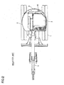
- FIG. 2 is a plan view of the compact excavator.
- FIG. 3 is a fragmentary front view of a counterweight disposed on a compact excavator according to a first embodiment of the present invention and its associated members as viewed from a side of an engine compartment.
- FIG. 4 is a cross-sectional view taken in the direction of arrow IV of FIG. 3 .
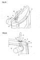
- FIG. 5 is a fragmentary perspective view of the counterweight disposed on the compact excavator according to the first embodiment and its associated members as viewed from a side of a rear wall of the counterweight.
- FIG. 6 is a fragmentary perspective view of the counterweight disposed on the compact excavator according to the first embodiment and its associated members as viewed from the side of the engine compartment.
- FIG. 7 is a fragmentary front view of a counterweight disposed on a compact excavator according to a second embodiment of the present invention and its associated members as viewed from a side of an engine compartment.
- FIG. 8 is a cross-sectional view taken in the direction of arrow VIII of FIG. 7 .
- FIG. 9 is a plan view of FIG. 7 .
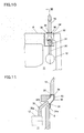
- FIG. 10 is a fragmentary front view of a counterweight disposed on a compact excavator according to a third embodiment of the present invention and its associated members as viewed from a side of an engine compartment.
- FIG. 11 is a cross-sectional view taken in the direction of arrow XI of FIG. 10 .
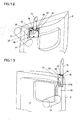
- FIG. 12 is a fragmentary perspective view of the counterweight disposed on the compact excavator according to the third embodiment and its associated members as viewed from a side of a rear wall of the counterweight.
- FIG. 13 is a fragmentary perspective view of the counterweight disposed on the compact excavator according to the third embodiment and its associated members as viewed from the side of the engine compartment.
- the working machine to which the present invention can be applied is, for example, a compact excavator as a small machine.
- This compact excavator is provided with a travel base 1, a revolving upperstructure mounted on the travel base 1, and working equipment 3 attached pivotally in up and down directions to the revolving upperstructure 2 and including a boom, an arm, and a bucket or the like to perform digging work of earth or sand or like work.
- a seat 4 is arranged on the revolving upperstructure 2.
- control devices 5 are arranged to operate the working equipment 3 and revolving upperstructure 2, respectively.
- a travel lever 6 is arranged to operate the travel base 1.
- a space above the seat 4 is covered by a canopy 7. Behind the seat 4, a cast counterweight 8 is disposed to assure a static balance. Between the seat 4 and the counterweight 2, an engine compartment is arranged to accommodate an engine, hydraulic pumps and the like none of which are shown in the drawings.
- the compact excavator as the first embodiment is provided with a muffler 12 for silencing exhaust gas discharged from the unillustrated engine accommodated in the engine compartment 11.
- This compact excavator is also provided with an exhaust path for releasing exhaust gas, which has been discharged from the muffler 12, to an outer side of the revolving upperstructure 2.
- This exhaust path includes a tailpipe 13 connected to the muffler 12 and an exhaust pipe 15 for releasing exhaust gas, which has been discharged from the tailpipe 13, to the outer side of the revolving upperstructure 2.
- the exhaust path also includes a passage 14 formed in an upper part of the counterweight 8 and accommodating an upper end portion of the tailpipe 13 inserted therein with a predetermined clearance 14a formed around the upper end portion such that the exhaust gas discharged from the tailpipe 13 can be guided to the exhaust pipe 15, for example, a restricted passage 14 having a diameter dimension that progressively decreases toward an upper end thereof.
- the exhaust pipe 15 has a flange 16 for securing the exhaust pipe 15 on an upper surface 9 of the counterweight 8 such that the restricted passage 14 is maintained in communication with the exhaust pipe 15.
- the flange 16 of the exhaust pipe 15 is formed, for example, in a rectangular shape, and is fixed by plural bolts 17 on the upper surface 9 of the counterweight 8.
- the tailpipe 13 is formed, for example, of a straight pipe extending in a vertical direction.
- the restricted passage 14 of the counterweight 8 has a vertical cross-section, for example, in a trapezoidal shape formed by vertically cutting a truncated circular cone.
- the exhaust gas from the engine is silenced in the muffler 12, is guided to the restricted passage 14 of the counter weight 8 from the tailpipe 13 connected to the muffler 12, is guided further to the exhaust pipe 15, and is then released to the outer side of the revolving upperstructure 2.
- vibrations of a vibration system which includes the muffler 12 arranged integrally with the unillustrated engine and the tailpipe 13, and those of another vibration system, which includes the counterweight 8 and exhaust pipe 15, are allowed in the clearance 14a between the tailpipe 13 and the restricted passage 14 of the counterweight 8, and therefore, these vibration systems can be maintained independent fromeach other without restraining each other.
- vibrations of the another vibration system including the counterweight 8 and exhaust pipe 15 are not transmitted to mounting parts for the unillustrated engine and the muffler 12 so that the mounting parts for these unillustrated engine and muffler 12 can be protected.
- the exhaust gas from the unillustrated engine passes through the restricted passage 14 formed in the counterweight 8 while being guided to the exhaust pipe 15 via the muffler 12 and tailpipe 13.
- the intense heat of the exhaust gas can hence be transferred to the counterweight 8.
- the temperature of exhaust gas to be released from the exhaust pipe 15 to the outer side of the revolving upperstructure 2 can be lowered more efficiently.
- the flow rate of the exhaust gas is increased so that the exhaust gas can be vigorously released from the exhaust pipe 15. As a consequence, excellent releasing performance can be assured for exhaust gas.
- the exhaust pipe 15 can be always maintained in a stable upright position, because the exhaust pipe 15 is held via the flange 16 on the counterweight 8 which has a thickness sufficient to form the restricted passage 14 and is at low risk of thermal deformation.
- a highly-reliable holding structure has been realized for the exhaust pipe 15.
- the length dimension of the exhaust pipe 15 can be increased to realize an enlargement of the exhaust pipe 15.
- the position of an exhaust-gas release port of the exhaust pipe 15 tends to be located close to the ground plane, it is especially effective to increase the length dimension of the exhaust pipe 15 as described above.
- the tailpipe 13 and the restricted passage 14 formed in the counterweight 8 can be formed in relatively simple shapes. Accordingly, the first embodiment is easy to manufacture, and has high practical utility.
- FIGS. 7 through 9 a compact excavator as a second embodiment of the present invention will be described hereinafter.
- the working machine according to this second embodiment is also a similar compact excavator as in the above-described first embodiment.
- a tailpipe 20 connected to the muffler 12 is formed of a vertical section 20a and an inclined section 20b.
- the vertical section 20a is connected to the muffler 12 and extends in a vertical direction.
- the inclined section 20b is arranged in conjunction with the vertical section 20a, progressively extends rearward toward an upper end thereof, and has an upper end portion inserted in a restricted passage 21 formed in the counterweight 8.
- the upper end portion 20b of the tailpipe 20 is inserted with a predetermined clearance 21a formed around the upper end portion such that the exhaust gas discharged from the tailpipe 20 can be guided to the exhaust pipe 15.
- the restricted passage 21 is formed of an inclined path having an inclination such that the inclined path progressively extends rearward toward an upper end thereof.
- a flange 22 of the exhaust pipe 15 is formed, for example, in a substantially oval shape in view of the shape of an upper edge portion of the counterweight 8.
- the flange 22 is fixed by bolts 23 on the upper surface 9 of the counterweight 8 to hold the exhaust pipe 15 on the counterweight 8.
- the remaining construction is equal to the corresponding construction in the above-described first embodiment.
- the counterweight 8 is also provided with the restricted passage 21 in which the upper end portion of the inclined section 20b of the tailpipe 20 is inserted. Similar to the above-described first embodiment, the intense heat of exhaust gas can therefore be transferred to the counterweight 8 at the restricted passage 21. Further, the flange 22 of the exhaust pipe 15 is fixed on the upper surface 9 of the counterweight 8 so that the heat of exhaust gas guided to the exhaust pipe 15 can be transferred to the counterweight 8 via the flange 22.
- the second embodiment can, therefore, bring about similar advantageous effects as the first embodiment.
- the exhaust pipe 15 can be always maintained in a stable upright position on the upper surface 9 of the counterweight 8 via the flange 22.
- the second embodiment can bring about similar advantageous effects as the first embodiment.
- the angle between the vertical section 20a and inclined section 20b of the tailpipe 20 and the length dimensions of the vertical section 20a and inclined section 20b can be set depending on the layout and position of the muffler 12. A higher degree of freedom or tolerance can, therefore, be enjoyed as to the layout designing of the muffler 12.
- the working machine according to this third embodiment is also a similar compact excavator as in the above-described first embodiment.
- the compact excavator as the third embodiment is provided with an exhaust-pipe holding member 32 which is fixed on the counterweight 8 and holds the exhaust pipe 15 in place.
- This exhaust-pipe holding member 32 is made of a similar cast iron as the counterweight 8.
- a tailpipe 30 connected to the muffler 12 is formed of a vertical section 30a connected to the muffler 12 and an inclined section 30b arranged in conjunction with the vertical section 30a. Further, an exhaust passage 31 is formed in the counterweight 8.
- This exhaust passage 31 an upper end portion of the inclined section 30b of the tailpipe 30 is inserted with a predetermined clearance 31a such that the exhaust gas discharged from the tailpipe 30 can be guided to the exhaust pipe 15.
- This exhaust passage 31 is set at the same diameter dimension along the entire length thereof.
- the exhaust-pipe holding member 32 is provided with a restricted passage 33 formed such that the restricted passage 33 is maintained in communication with the exhaust passage 31 and has a diameter dimension progressively decreasing toward an upper end thereof.
- the exhaust pipe 15 has a flange 35 via which the exhaust pipe 15 is fixed on an upper surface 34 of the exhaust-pipe holding member 32 such that the restricted passage 33 of the exhaust-pipe holding member 32 is maintained in communication with the exhaust pipe 15.
- This flange 35 is fixed by plural bolts 36 on the upper surface 34 of the exhaust-pipe holding member 32.
- the exhaust-pipe holding member 32 is fixed by plural bolts 37 on an upper part of a rear wall of the counterweight 8. The remaining construction is equal to the corresponding construction in the above-described first embodiment.
- the counterweight 8 is also provided with the exhaust passage 31 in which the upper end portion of the inclined section 30b of the tailpipe 30 is inserted. Similar to the above-described first embodiment, the intense heat of exhaust gas can therefore be transferred at the exhaust passage 31 to the counterweight 8 via the exhaust-pipe holding member 32. Further, the heat of exhaust gas guided to the exhaust pipe 15 can be transferred to the counterweight 8 via the flange 35 of the exhaust pipe 15 and the exhaust-pipe holding member 32.
- the second embodiment can, therefore, bring about similar advantageous effects as the first embodiment.
- the angle between the vertical section 30a and inclined section 30b of the tailpipe 30 and the length dimensions of the vertical section 30a and inclined section 30b can be set depending on the layout and position of the muffler 12. Similar to the second embodiment, a higher degree of freedom or tolerance can, therefore, be enjoyed as to the layout designing of the muffler 12.
- the exhaust passage 31 formed in the counterweight 8 is set at the same diameter dimension over the entire length thereof. Therefore, the manufacture of the counterweight 8 is easy, and the manufacturing cost of the counterweight 8 can be limited low.
- the exhaust pipe 15 can be always maintained in a stable upright position, because the exhaust pipe 15 is held via the flange 35 on the exhaust-pipe holding member 32 which has a thickness sufficient to form the restricted passage 33 and is at low risk of thermal deformation.
- the second embodiment can bring about similar advantageous effects as the first embodiment.
- this third embodiment is effective especially in the case of a small compact excavator in which the thickness dimension of the counterweight 8 has to be set relatively small or a small compact excavator in which a layout space can be hardly found for the exhaust pipe 15 on the upper surface of the counterweight 8.
Landscapes
- Engineering & Computer Science (AREA)
- General Engineering & Computer Science (AREA)
- Mining & Mineral Resources (AREA)
- Civil Engineering (AREA)
- Structural Engineering (AREA)
- Chemical & Material Sciences (AREA)
- Combustion & Propulsion (AREA)
- Mechanical Engineering (AREA)
- Cooling, Air Intake And Gas Exhaust, And Fuel Tank Arrangements In Propulsion Units (AREA)
- Component Parts Of Construction Machinery (AREA)
- Exhaust Silencers (AREA)
Abstract
Description
- This application claims the priority of Japanese Patent Application
2010-203461 filed September 10, 2010 - The present invention relates to a working machine such as a compact excavator, which is provided with an exhaust path for releasing exhaust gas, which has been discharged from a muffler, to an outer side of a revolving upperstructure and makes use of a counterweight for the formation of the exhaust path.
- As a conventional technology of this kind, there is the technology disclosed in
JP-A-2002-70077 - According to the above-described conventional technology, intense heat of exhaust gas is transferred to the counterweight via the exhaust pipe in which the upper end portion of the tailpipe is inserted and also via the cover plate on which the exhaust pipe is fixed. The conventional technology, therefore, contributes to lowering the temperature of exhaust gas which is to be released to the outer side of the revolving upper structure. However, the conventional technology involves a problem in that sufficient heat transfer effect can be hardly obtained by the counterweight because the intense heat of the exhaust gas is conducted to the counterweight by way of the exhaust pipe and cover plate.
- In this conventional technology, the intense heat of the exhaust gas guided to the exhaust pipe via the tailpipe is conducted to the cover plate that holds the exhaust pipe in place, and the thickness dimension of the cover plate is set small. There is, accordingly, a potential problem that the cover plate may undergo a deflection under the intense heat. If such a deflection occurs, a problem may arise in that the exhaust pipe held in place by the cover plate may lean to change the releasing direction of exhaust gas.
- With the above-described circumstances of the conventional technology in view, the present invention has as an object thereof the provision of a working machine which can more efficiently lower the temperature of exhaust gas to be released from an exhaust pipe to an outside of a revolving upperstructure.
- To achieve the above-described object, the present invention provides, in one aspect thereof, a working machine provided with a revolving upperstructure, working equipment attached to the revolving upperstructure, an engine compartment arranged on the revolving upperstructure, a counterweight disposed behind the engine compartment, a muffler for silencing exhaust gas discharged from an engine accommodated in the engine compartment, and an exhaust path for releasing exhaust gas, which has been discharged from the muffler, to an outer side of the revolving upperstructure, said exhaust path including a tailpipe connected to the muffler and an exhaust pipe for releasing exhaust gas, which has been discharged from the tailpipe, to the outer side of the revolving upperstructure, and said counterweight being utilized for the formation of the exhaust path, wherein the exhaust path comprises a passage formed in the counterweight and accommodating an upper end portion of the tailpipe inserted therein with a predetermined clearance formed around the upper end portion such that the exhaust gas discharged from the tailpipe can be guided to the exhaust pipe.
- According to the present invention constructed as described above, the exhaust gas from the engine passes through the passage formed in the counterweight while being guided to the exhaust pipe via the muffler and tailpipe. In this passage, intense heat of the exhaust gas can thus be transferred to the counterweight. As a result, the temperature of the exhaust gas to be released from the exhaust pipe to the outside of the revolving upperstructure can be lowered more efficiently.
- Preferably, the passage formed in the counterweight may comprise a restricted passage having a diameter dimension that progressively decreases toward an upper end thereof; and the exhaust pipe may have a flange for securing the exhaust pipe on an upper surface of the counterweight such that the restricted passage is maintained in communication with the exhaust pipe.
- According to the present invention constructed as described immediately above, in the restricted passage formed in the counterweight, the intense heat of the exhaust gas guided to the restricted passage can be transferred to the counterweight, and owing to this restricted passage, the flow rate of the exhaust gas is increased so that the exhaust gas can be vigorously released from the exhaust pipe. As the flange of the exhaust pipe is secured on the upper surface of the counterweight, the intense heat of the exhaust gas that passes through the exhaust pipe can be conducted to the counterweight via the flange. By this conduction, the temperature of the exhaust gas can be also lowered. Further, the exhaust pipe can be always maintained in a stable upright position, because the exhaust pipe is held via the flange on the counterweight which has a thickness sufficient to form the restricted passage and is at low risk of thermal deformation.
- Preferably, the tailpipe may comprise a straight pipe extending in a vertical direction, and the restricted passage may have a vertical cross-section in a trapezoidal shape formed by vertically cutting a truncated circular cone.
- According to the present invention constructed as described immediately above, the tailpipe and the restricted passage formed in the counterweight can be formed in relatively simple shapes.
- Preferably, the tailpipe may comprise a vertical section connected to the muffler and extending in a vertical direction, and an inclined section arranged in conjunction with the vertical section, progressively extending rearward toward an upper end thereof and having an upper end portion inserted in the restricted pas sage formed in the counterweight; and the restricted passage may comprise an inclined path having an inclination such that the restricted passage progressively extends rearward toward an upper end thereof.
- According to the present invention constructed as described immediately above, the angle between the vertical section and inclined section of the tailpipe and the length dimensions of the vertical section and inclined section can be set depending on the layout and position of the muffler.
- Preferably, the working machine may be further provided with an exhaust-pipe holding member fixed on the counterweight and holding the exhaust pipe in place; the passage formed in the counterweight may comprise an exhaust passage set at a same diameter dimension over an entire length thereof; the exhaust-pipe holding member may be provided with a restricted passage communicating to the exhaust passage and having a diameter dimension that progressively decreases toward an upper end thereof; and the exhaust pipe may have a flange for securing the exhaust pipe on an upper surface of the exhaust-pipe holding member such that the restricted passage of the exhaust-pipe holding member is maintained in communication with the exhaust pipe.
- According to the present invention constructed as described immediately above, at the exhaust passage formed in the counterweight, the intense heat of the exhaust gas can be transferred to the counterweight, whereby the temperature of the exhaust gas can be lowered. Further, heat can also be transferred to the counterweight via the restricted passage of the exhaust-pipe holding member arranged integrally with the counterweight, and through this restricted passage of the exhaust-pipe holding member, the flow rate of the exhaust gas is increased so that the exhaust gas can be vigorously released from the exhaust pipe. The heat of the exhaust gas, which has been conducted from the flange of the exhaust pipe, can also be transferred to the counterweight. Further, the fabrication of the counterweight is easy as the exhaust passage formed in the counterweight is set at the same diameter dimension over the entire length thereof. Furthermore, the exhaust pipe can be always maintained in a stable upright position, because the exhaust pipe is held via the flange on the counterweight which has a thickness sufficient to form the restricted passage and is at low risk of thermal deformation.
- As the exhaust path for releasing exhaust gas, which has been discharged from the muffler, to the outer side of the revolving upperstructure includes the passage formed in the counterweight and accommodating the upper end portion of the tailpipe inserted therein with the predetermined clearance formed around the upper end portion such that the exhaust gas discharged from the tailpipe can be guided to the exhaust pipe. At this passage, the intense heat of the exhaust gas can thus be transferred to the counterweight so that the temperature of the exhaust gas can be lowered more efficiently. Compared with before, it is hence possible to lessen the adverse effects which the heat of exhaust gas released to the outer side of the revolving upperstructure gives to the surrounding environment.
-
FIG. 1 is a side view of a compact excavator as one example of a working machine to which the present invention can be applied. -
FIG. 2 is a plan view of the compact excavator. -
FIG. 3 is a fragmentary front view of a counterweight disposed on a compact excavator according to a first embodiment of the present invention and its associated members as viewed from a side of an engine compartment. -
FIG. 4 is a cross-sectional view taken in the direction of arrow IV ofFIG. 3 . -
FIG. 5 is a fragmentary perspective view of the counterweight disposed on the compact excavator according to the first embodiment and its associated members as viewed from a side of a rear wall of the counterweight. -
FIG. 6 is a fragmentary perspective view of the counterweight disposed on the compact excavator according to the first embodiment and its associated members as viewed from the side of the engine compartment. -
FIG. 7 is a fragmentary front view of a counterweight disposed on a compact excavator according to a second embodiment of the present invention and its associated members as viewed from a side of an engine compartment. -
FIG. 8 is a cross-sectional view taken in the direction of arrow VIII ofFIG. 7 . -
FIG. 9 is a plan view ofFIG. 7 . -
FIG. 10 is a fragmentary front view of a counterweight disposed on a compact excavator according to a third embodiment of the present invention and its associated members as viewed from a side of an engine compartment. -
FIG. 11 is a cross-sectional view taken in the direction of arrow XI ofFIG. 10 . -
FIG. 12 is a fragmentary perspective view of the counterweight disposed on the compact excavator according to the third embodiment and its associated members as viewed from a side of a rear wall of the counterweight. -
FIG. 13 is a fragmentary perspective view of the counterweight disposed on the compact excavator according to the third embodiment and its associated members as viewed from the side of the engine compartment. - The embodiments of the working machine according to the present invention will hereinafter be described with reference to the accompanying drawings.
- Referring first to
FIGS. 1 and2 , the working machine to which the present invention can be applied is, for example, a compact excavator as a small machine. This compact excavator is provided with atravel base 1, a revolving upperstructure mounted on thetravel base 1, and workingequipment 3 attached pivotally in up and down directions to the revolvingupperstructure 2 and including a boom, an arm, and a bucket or the like to perform digging work of earth or sand or like work. On the revolvingupperstructure 2, a seat 4 is arranged. Laterally to the seat 4, control devices 5 are arranged to operate theworking equipment 3 and revolvingupperstructure 2, respectively. In front of the seat 4, atravel lever 6 is arranged to operate thetravel base 1. A space above the seat 4 is covered by acanopy 7. Behind the seat 4, acast counterweight 8 is disposed to assure a static balance. Between the seat 4 and thecounterweight 2, an engine compartment is arranged to accommodate an engine, hydraulic pumps and the like none of which are shown in the drawings. - With reference to
FIGS. 3 through 6 , a description will next be made of a compact excavator as the first embodiment of the working machine according to the present invention. The compact excavator as the first embodiment is provided with amuffler 12 for silencing exhaust gas discharged from the unillustrated engine accommodated in theengine compartment 11. This compact excavator is also provided with an exhaust path for releasing exhaust gas, which has been discharged from themuffler 12, to an outer side of the revolvingupperstructure 2. This exhaust path includes atailpipe 13 connected to themuffler 12 and anexhaust pipe 15 for releasing exhaust gas, which has been discharged from thetailpipe 13, to the outer side of the revolvingupperstructure 2. - The exhaust path also includes a
passage 14 formed in an upper part of thecounterweight 8 and accommodating an upper end portion of thetailpipe 13 inserted therein with apredetermined clearance 14a formed around the upper end portion such that the exhaust gas discharged from thetailpipe 13 can be guided to theexhaust pipe 15, for example, a restrictedpassage 14 having a diameter dimension that progressively decreases toward an upper end thereof. - The
exhaust pipe 15 has aflange 16 for securing theexhaust pipe 15 on anupper surface 9 of thecounterweight 8 such that the restrictedpassage 14 is maintained in communication with theexhaust pipe 15. Theflange 16 of theexhaust pipe 15 is formed, for example, in a rectangular shape, and is fixed byplural bolts 17 on theupper surface 9 of thecounterweight 8. - The
tailpipe 13 is formed, for example, of a straight pipe extending in a vertical direction. The restrictedpassage 14 of thecounterweight 8 has a vertical cross-section, for example, in a trapezoidal shape formed by vertically cutting a truncated circular cone. - According to the compact excavator as the first embodiment, the exhaust gas from the engine is silenced in the
muffler 12, is guided to the restrictedpassage 14 of thecounter weight 8 from thetailpipe 13 connected to themuffler 12, is guided further to theexhaust pipe 15, and is then released to the outer side of the revolvingupperstructure 2. - Along the
muffler 12 and the exhaust path, vibrations of a vibration system, which includes themuffler 12 arranged integrally with the unillustrated engine and thetailpipe 13, and those of another vibration system, which includes thecounterweight 8 andexhaust pipe 15, are allowed in theclearance 14a between thetailpipe 13 and the restrictedpassage 14 of thecounterweight 8, and therefore, these vibration systems can be maintained independent fromeach other without restraining each other. Owing to this feature, vibrations of the another vibration system including thecounterweight 8 andexhaust pipe 15 are not transmitted to mounting parts for the unillustrated engine and themuffler 12 so that the mounting parts for these unillustrated engine andmuffler 12 can be protected. - When the exhaust gas is guided from the
tailpipe 13 to the restrictedpassage 14 of thecounterweight 8, an air stream around thetailpipe 13 is drawn into the restrictedpassage 14 through theclearance 14a. By this air stream, the intense heat of the exhaust gas is cooled. - According to the compact excavator constructed as the first embodiment as described above, the exhaust gas from the unillustrated engine passes through the restricted
passage 14 formed in thecounterweight 8 while being guided to theexhaust pipe 15 via themuffler 12 andtailpipe 13. At this restricted passage, the intense heat of the exhaust gas can hence be transferred to thecounterweight 8. As a consequence, the temperature of exhaust gas to be released from theexhaust pipe 15 to the outer side of the revolvingupperstructure 2 can be lowered more efficiently. - As the
flange 16 of theexhaust pipe 15 is secured on theupper surface 9 of thecounterweight 8, the heat of the exhaust gas that passes through theexhaust pipe 15 can be conducted to thecounterweight 8 via theflange 16. These transfer and conduction of heat can lessen the adverse effects which the heat of exhaust gas released to the outer side of the revolving upperstructure gives to the surrounding environment. - Owing to the restricted
passage 14 formed in thecounterweight 8, the flow rate of the exhaust gas is increased so that the exhaust gas can be vigorously released from theexhaust pipe 15. As a consequence, excellent releasing performance can be assured for exhaust gas. - Further, the
exhaust pipe 15 can be always maintained in a stable upright position, because theexhaust pipe 15 is held via theflange 16 on thecounterweight 8 which has a thickness sufficient to form the restrictedpassage 14 and is at low risk of thermal deformation. As a consequence, a highly-reliable holding structure has been realized for theexhaust pipe 15. As theexhaust pipe 15 can be stably held, the length dimension of theexhaust pipe 15 can be increased to realize an enlargement of theexhaust pipe 15. For the compact excavator that the position of an exhaust-gas release port of theexhaust pipe 15 tends to be located close to the ground plane, it is especially effective to increase the length dimension of theexhaust pipe 15 as described above. When designed to release exhaust gas at as high a position as possible, it is possible to realize the protection of plants of relatively low height, which are planted around the compact excavator, from the intense heat of exhaust gas. - According to this first embodiment, the
tailpipe 13 and the restrictedpassage 14 formed in thecounterweight 8 can be formed in relatively simple shapes. Accordingly, the first embodiment is easy to manufacture, and has high practical utility. - Referring next to
FIGS. 7 through 9 , a compact excavator as a second embodiment of the present invention will be described hereinafter. - The working machine according to this second embodiment is also a similar compact excavator as in the above-described first embodiment. In the compact excavator as the second embodiment, a
tailpipe 20 connected to themuffler 12 is formed of avertical section 20a and aninclined section 20b. Thevertical section 20a is connected to themuffler 12 and extends in a vertical direction. Theinclined section 20b is arranged in conjunction with thevertical section 20a, progressively extends rearward toward an upper end thereof, and has an upper end portion inserted in a restrictedpassage 21 formed in thecounterweight 8. - In this restricted
passage 21, theupper end portion 20b of thetailpipe 20 is inserted with apredetermined clearance 21a formed around the upper end portion such that the exhaust gas discharged from thetailpipe 20 can be guided to theexhaust pipe 15. As depicted inFIG. 8 , the restrictedpassage 21 is formed of an inclined path having an inclination such that the inclined path progressively extends rearward toward an upper end thereof. As illustrated inFIG. 9 , aflange 22 of theexhaust pipe 15 is formed, for example, in a substantially oval shape in view of the shape of an upper edge portion of thecounterweight 8. Theflange 22 is fixed bybolts 23 on theupper surface 9 of thecounterweight 8 to hold theexhaust pipe 15 on thecounterweight 8. The remaining construction is equal to the corresponding construction in the above-described first embodiment. - In this compact excavator as the second embodiment, the
counterweight 8 is also provided with the restrictedpassage 21 in which the upper end portion of theinclined section 20b of thetailpipe 20 is inserted. Similar to the above-described first embodiment, the intense heat of exhaust gas can therefore be transferred to thecounterweight 8 at the restrictedpassage 21. Further, theflange 22 of theexhaust pipe 15 is fixed on theupper surface 9 of thecounterweight 8 so that the heat of exhaust gas guided to theexhaust pipe 15 can be transferred to thecounterweight 8 via theflange 22. The second embodiment can, therefore, bring about similar advantageous effects as the first embodiment. - Owing to the restricted
passage 21 formed in thecounterweight 8, excellent releasing performance can be obtained for exhaust gas as in the first embodiment. - Further, the
exhaust pipe 15 can be always maintained in a stable upright position on theupper surface 9 of thecounterweight 8 via theflange 22. In this respect too, the second embodiment can bring about similar advantageous effects as the first embodiment. - In the compact excavator as the second embodiment, the angle between the
vertical section 20a andinclined section 20b of thetailpipe 20 and the length dimensions of thevertical section 20a andinclined section 20b can be set depending on the layout and position of themuffler 12. A higher degree of freedom or tolerance can, therefore, be enjoyed as to the layout designing of themuffler 12. - With reference to
FIGS. 10 through 13 , a description will next be made of a compact excavator as a third embodiment of the present invention. - The working machine according to this third embodiment is also a similar compact excavator as in the above-described first embodiment. The compact excavator as the third embodiment is provided with an exhaust-
pipe holding member 32 which is fixed on thecounterweight 8 and holds theexhaust pipe 15 in place. This exhaust-pipe holding member 32 is made of a similar cast iron as thecounterweight 8. Similar to the second embodiment, atailpipe 30 connected to themuffler 12 is formed of avertical section 30a connected to themuffler 12 and aninclined section 30b arranged in conjunction with thevertical section 30a. Further, anexhaust passage 31 is formed in thecounterweight 8. In thisexhaust passage 31, an upper end portion of theinclined section 30b of thetailpipe 30 is inserted with apredetermined clearance 31a such that the exhaust gas discharged from thetailpipe 30 can be guided to theexhaust pipe 15. Thisexhaust passage 31 is set at the same diameter dimension along the entire length thereof. - The exhaust-
pipe holding member 32 is provided with a restrictedpassage 33 formed such that the restrictedpassage 33 is maintained in communication with theexhaust passage 31 and has a diameter dimension progressively decreasing toward an upper end thereof. Further, theexhaust pipe 15 has aflange 35 via which theexhaust pipe 15 is fixed on anupper surface 34 of the exhaust-pipe holding member 32 such that the restrictedpassage 33 of the exhaust-pipe holding member 32 is maintained in communication with theexhaust pipe 15. Thisflange 35 is fixed byplural bolts 36 on theupper surface 34 of the exhaust-pipe holding member 32. As depicted inFIG. 12 , the exhaust-pipe holding member 32 is fixed byplural bolts 37 on an upper part of a rear wall of thecounterweight 8. The remaining construction is equal to the corresponding construction in the above-described first embodiment. - In this compact excavator as the third embodiment, the
counterweight 8 is also provided with theexhaust passage 31 in which the upper end portion of theinclined section 30b of thetailpipe 30 is inserted. Similar to the above-described first embodiment, the intense heat of exhaust gas can therefore be transferred at theexhaust passage 31 to thecounterweight 8 via the exhaust-pipe holding member 32. Further, the heat of exhaust gas guided to theexhaust pipe 15 can be transferred to thecounterweight 8 via theflange 35 of theexhaust pipe 15 and the exhaust-pipe holding member 32. The second embodiment can, therefore, bring about similar advantageous effects as the first embodiment. - Owing to the restricted
passage 33 formed in the exhaust-pipe holding member 32, excellent releasing performance can be obtained for exhaust gas as in the first embodiment. - The angle between the
vertical section 30a andinclined section 30b of thetailpipe 30 and the length dimensions of thevertical section 30a andinclined section 30b can be set depending on the layout and position of themuffler 12. Similar to the second embodiment, a higher degree of freedom or tolerance can, therefore, be enjoyed as to the layout designing of themuffler 12. - The
exhaust passage 31 formed in thecounterweight 8 is set at the same diameter dimension over the entire length thereof. Therefore, the manufacture of thecounterweight 8 is easy, and the manufacturing cost of thecounterweight 8 can be limited low. - Further, the
exhaust pipe 15 can be always maintained in a stable upright position, because theexhaust pipe 15 is held via theflange 35 on the exhaust-pipe holding member 32 which has a thickness sufficient to form the restrictedpassage 33 and is at low risk of thermal deformation. In this respect too, the second embodiment can bring about similar advantageous effects as the first embodiment. - It is to be noted that despite the formation of the
exhaust passage 31 in thecounterweight 8, this third embodiment is effective especially in the case of a small compact excavator in which the thickness dimension of thecounterweight 8 has to be set relatively small or a small compact excavator in which a layout space can be hardly found for theexhaust pipe 15 on the upper surface of thecounterweight 8.
Claims (5)
- A working machine provided with a revolving upperstructure, working equipment attached to the revolving upperstructure, an engine compartment arranged on the revolving upperstructure, a counterweight disposed behind the engine compartment, a muffler for silencing exhaust gas discharged from an engine accommodated in the engine compartment, and an exhaust path for releasing exhaust gas, which has been discharged from the muffler, to an outer side of the revolving upperstructure, said exhaust path including a tailpipe connected to the muffler and an exhaust pipe for releasing exhaust gas, which has been discharged from the tailpipe, to the outer side of the revolving upperstructure, and said counterweight being utilized for the formation of the exhaust path, wherein:the exhaust path comprises a passage formed in the counterweight and accommodating an upper end portion of the tailpipe inserted therein with a predetermined clearance formed around the upper end portion such that the exhaust gas discharged from the tailpipe can be guided to the exhaust pipe.
- The working machine according to claim 1, wherein:the passage formed in the counterweight comprises a restricted passage having a diameter dimension that progressively decreases toward an upper end thereof; andthe exhaust pipe has a flange for securing the exhaust pipe on an upper surface of the counterweight such that the restricted passage is maintained in communication with the exhaust pipe.
- The working machine according to claim 2, wherein:the tailpipe comprises a straight pipe extending in a vertical direction; andthe restricted passage has a vertical cross-section in a trapezoidal shape formed by vertically cutting a truncated circular cone.
- The working machine according to claim 2, wherein:the tailpipe comprises a vertical section connected to the muffler and extending in a vertical direction, and an inclined section arranged in conjunction with the vertical section, progressively extending rearward toward an upper end thereof and having an upper end portion inserted in the restricted passage formed in the counterweight; andthe restricted passage comprises an inclined path having an inclination such that the restricted passage progressively extends rearward toward an upper end thereof.
- The working machine according to claim 1, wherein:the working machine is further provided with an exhaust-pipe holding member fixed on the counterweight and holding the exhaust pipe in place;the passage formed in the counterweight comprises an exhaust passage set at a same diameter dimension over an entire length thereof;the exhaust-pipe holding member is provided with a restricted passage communicating to the exhaust passage and having a diameter dimension that progressively decreases toward an upper end thereof; andthe exhaust pipe has a flange for securing the exhaust pipe on an upper surface of the exhaust-pipe holding member such that the restricted passage of the exhaust-pipe holding member is maintained in communication with the exhaust pipe.
Applications Claiming Priority (1)
| Application Number | Priority Date | Filing Date | Title |
|---|---|---|---|
| JP2010203461A JP5368398B2 (en) | 2010-09-10 | 2010-09-10 | Work machine |
Publications (2)
| Publication Number | Publication Date |
|---|---|
| EP2428620A1 true EP2428620A1 (en) | 2012-03-14 |
| EP2428620B1 EP2428620B1 (en) | 2013-10-23 |
Family
ID=44677669
Family Applications (1)
| Application Number | Title | Priority Date | Filing Date |
|---|---|---|---|
| EP11180602.2A Not-in-force EP2428620B1 (en) | 2010-09-10 | 2011-09-08 | Working machine |
Country Status (3)
| Country | Link |
|---|---|
| US (1) | US8443932B2 (en) |
| EP (1) | EP2428620B1 (en) |
| JP (1) | JP5368398B2 (en) |
Cited By (1)
| Publication number | Priority date | Publication date | Assignee | Title |
|---|---|---|---|---|
| GB2489333A (en) * | 2010-04-12 | 2012-09-26 | Nexen Lift Trucks Ltd | A Counterweight |
Families Citing this family (9)
| Publication number | Priority date | Publication date | Assignee | Title |
|---|---|---|---|---|
| JP2012106836A (en) * | 2010-11-17 | 2012-06-07 | Tcm Corp | Diesel particulate filter mounting structure for industrial vehicle |
| JP5883324B2 (en) * | 2012-03-27 | 2016-03-15 | 日立建機株式会社 | Work machine |
| JP5759408B2 (en) * | 2012-03-27 | 2015-08-05 | 日立建機株式会社 | Mini excavator |
| JP5806636B2 (en) * | 2012-04-02 | 2015-11-10 | 日立建機株式会社 | Work machine |
| JP5839695B2 (en) * | 2012-04-02 | 2016-01-06 | 日立建機株式会社 | Work machine |
| JP5955667B2 (en) * | 2012-07-02 | 2016-07-20 | 住友建機株式会社 | Exhaust device for construction machine and construction machine provided with exhaust device |
| JP6411973B2 (en) * | 2015-08-27 | 2018-10-24 | 株式会社日立建機ティエラ | Small excavator |
| JP7142505B2 (en) * | 2018-07-13 | 2022-09-27 | 株式会社小松製作所 | work vehicle |
| US11732633B2 (en) * | 2022-01-04 | 2023-08-22 | Caterpillar Inc. | Exhaust discharge system |
Citations (8)
| Publication number | Priority date | Publication date | Assignee | Title |
|---|---|---|---|---|
| JPS508701U (en) * | 1973-05-22 | 1975-01-29 | ||
| DE2543683A1 (en) * | 1975-09-30 | 1977-04-07 | Linde Ag | Ballast for forklifts or counterweights of other machines - produced from particulate waste material and resinous binder |
| JPH1182010A (en) * | 1997-09-03 | 1999-03-26 | Sumitomo Constr Mach Co Ltd | Exhaust system for construction machinery |
| JP2002070077A (en) | 2000-09-04 | 2002-03-08 | Shin Caterpillar Mitsubishi Ltd | Exhaust silencer with built-in counterweight of construction equipment |
| DE102004026587A1 (en) * | 2004-06-01 | 2005-12-22 | Linde Ag | Industrial truck, especially fork lift stacker, has cooling medium circuit contained within counterweight and is constructed with gravity force circulating of cooling medium |
| JP2006070844A (en) * | 2004-09-03 | 2006-03-16 | Toyota Industries Corp | Exhaust structure in industrial vehicles |
| JP2007321392A (en) * | 2006-05-31 | 2007-12-13 | Shin Caterpillar Mitsubishi Ltd | Counter weight for work machine |
| JP2010203461A (en) | 2009-02-27 | 2010-09-16 | Yazaki Corp | Locking tool mounting structure to panel and locking tool |
Family Cites Families (13)
| Publication number | Priority date | Publication date | Assignee | Title |
|---|---|---|---|---|
| US2242494A (en) * | 1932-04-07 | 1941-05-20 | Austin M Wolf | Ventilating and cooling system for motor vehicles |
| US2850314A (en) * | 1952-11-17 | 1958-09-02 | Gen Motors Corp | Bumper exhaust |
| US3792722A (en) * | 1972-01-12 | 1974-02-19 | Waterloo Foundry Co Inc | Exhaust pipe attachment |
| US4388804A (en) * | 1981-08-17 | 1983-06-21 | J. I. Case Company | Exhaust assembly for tractors |
| JPH0738650Y2 (en) * | 1989-05-12 | 1995-09-06 | 株式会社クボタ | Earthmoving machine engine exhaust structure |
| JPH10266853A (en) * | 1997-03-25 | 1998-10-06 | Sumitomo Constr Mach Co Ltd | Engine exhaust structure of construction machinery |
| US6220387B1 (en) * | 1999-10-21 | 2001-04-24 | Mathew S. Hoppes | Exhaust muffler |
| JP4380670B2 (en) * | 2006-08-10 | 2009-12-09 | トヨタ自動車株式会社 | Car rear structure |
| US7779961B2 (en) * | 2006-11-20 | 2010-08-24 | Matte Francois | Exhaust gas diffuser |
| US7971432B2 (en) * | 2007-07-13 | 2011-07-05 | Paccar Inc | Flow diffuser for exhaust pipe |
| JP5101324B2 (en) * | 2008-02-07 | 2012-12-19 | 日立建機株式会社 | Arrangement structure of NOx reduction device for construction machinery |
| JP5401944B2 (en) * | 2008-11-25 | 2014-01-29 | コベルコ建機株式会社 | Muffler mounting device for construction machinery |
| US7958966B2 (en) * | 2009-03-31 | 2011-06-14 | Paccar Inc | Exhaust stack fairing |
-
2010
- 2010-09-10 JP JP2010203461A patent/JP5368398B2/en not_active Expired - Fee Related
-
2011
- 2011-09-08 US US13/228,004 patent/US8443932B2/en not_active Expired - Fee Related
- 2011-09-08 EP EP11180602.2A patent/EP2428620B1/en not_active Not-in-force
Patent Citations (8)
| Publication number | Priority date | Publication date | Assignee | Title |
|---|---|---|---|---|
| JPS508701U (en) * | 1973-05-22 | 1975-01-29 | ||
| DE2543683A1 (en) * | 1975-09-30 | 1977-04-07 | Linde Ag | Ballast for forklifts or counterweights of other machines - produced from particulate waste material and resinous binder |
| JPH1182010A (en) * | 1997-09-03 | 1999-03-26 | Sumitomo Constr Mach Co Ltd | Exhaust system for construction machinery |
| JP2002070077A (en) | 2000-09-04 | 2002-03-08 | Shin Caterpillar Mitsubishi Ltd | Exhaust silencer with built-in counterweight of construction equipment |
| DE102004026587A1 (en) * | 2004-06-01 | 2005-12-22 | Linde Ag | Industrial truck, especially fork lift stacker, has cooling medium circuit contained within counterweight and is constructed with gravity force circulating of cooling medium |
| JP2006070844A (en) * | 2004-09-03 | 2006-03-16 | Toyota Industries Corp | Exhaust structure in industrial vehicles |
| JP2007321392A (en) * | 2006-05-31 | 2007-12-13 | Shin Caterpillar Mitsubishi Ltd | Counter weight for work machine |
| JP2010203461A (en) | 2009-02-27 | 2010-09-16 | Yazaki Corp | Locking tool mounting structure to panel and locking tool |
Cited By (2)
| Publication number | Priority date | Publication date | Assignee | Title |
|---|---|---|---|---|
| GB2489333A (en) * | 2010-04-12 | 2012-09-26 | Nexen Lift Trucks Ltd | A Counterweight |
| GB2489333B (en) * | 2010-04-12 | 2013-05-22 | Nexen Lift Trucks Ltd | A coupling |
Also Published As
| Publication number | Publication date |
|---|---|
| US8443932B2 (en) | 2013-05-21 |
| US20120061177A1 (en) | 2012-03-15 |
| EP2428620B1 (en) | 2013-10-23 |
| JP2012057414A (en) | 2012-03-22 |
| JP5368398B2 (en) | 2013-12-18 |
Similar Documents
| Publication | Publication Date | Title |
|---|---|---|
| US8443932B2 (en) | Working machine | |
| EP2735712B1 (en) | Construction machine | |
| CN104185708B (en) | Bulldozer | |
| WO2002040782A1 (en) | Construction machine | |
| EP1091048A2 (en) | Construction machine | |
| JP5543673B1 (en) | Exhaust treatment unit | |
| JP2015098726A (en) | Construction machine | |
| JP4953191B2 (en) | Construction machinery | |
| US9347350B2 (en) | Engine unit | |
| JP6298743B2 (en) | Construction machinery | |
| US10060094B2 (en) | Arrangement structure for a reducing agent tank for a construction machine | |
| EP2863029B1 (en) | Exhaust gas discharge apparatus for construction machine | |
| EP2366836A2 (en) | Construction machine | |
| JP2017036538A (en) | Air discharge structure of construction machine | |
| JP6754351B2 (en) | Construction machinery | |
| WO2015059982A1 (en) | Hydraulic shovel | |
| WO2019187571A1 (en) | Work machine | |
| JP5320348B2 (en) | Work vehicle | |
| JP5731426B2 (en) | Work machine | |
| JP2017160639A (en) | Exhaust device for work machine | |
| JP5839695B2 (en) | Work machine | |
| JP4278581B2 (en) | Tractor front guard | |
| JP5883324B2 (en) | Work machine | |
| JP5806636B2 (en) | Work machine | |
| JP2013181323A (en) | Construction machine |
Legal Events
| Date | Code | Title | Description |
|---|---|---|---|
| 17P | Request for examination filed |
Effective date: 20110908 |
|
| AK | Designated contracting states |
Kind code of ref document: A1 Designated state(s): AL AT BE BG CH CY CZ DE DK EE ES FI FR GB GR HR HU IE IS IT LI LT LU LV MC MK MT NL NO PL PT RO RS SE SI SK SM TR |
|
| AX | Request for extension of the european patent |
Extension state: BA ME |
|
| PUAI | Public reference made under article 153(3) epc to a published international application that has entered the european phase |
Free format text: ORIGINAL CODE: 0009012 |
|
| REG | Reference to a national code |
Ref country code: DE Ref legal event code: R079 Ref document number: 602011003454 Country of ref document: DE Free format text: PREVIOUS MAIN CLASS: E02F0009180000 Ipc: E02F0009080000 |
|
| GRAP | Despatch of communication of intention to grant a patent |
Free format text: ORIGINAL CODE: EPIDOSNIGR1 |
|
| RIC1 | Information provided on ipc code assigned before grant |
Ipc: F01N 13/08 20100101ALI20130423BHEP Ipc: E02F 9/18 20060101ALI20130423BHEP Ipc: E02F 9/08 20060101AFI20130423BHEP |
|
| INTG | Intention to grant announced |
Effective date: 20130508 |
|
| GRAS | Grant fee paid |
Free format text: ORIGINAL CODE: EPIDOSNIGR3 |
|
| GRAA | (expected) grant |
Free format text: ORIGINAL CODE: 0009210 |
|
| AK | Designated contracting states |
Kind code of ref document: B1 Designated state(s): AL AT BE BG CH CY CZ DE DK EE ES FI FR GB GR HR HU IE IS IT LI LT LU LV MC MK MT NL NO PL PT RO RS SE SI SK SM TR |
|
| REG | Reference to a national code |
Ref country code: GB Ref legal event code: FG4D |
|
| REG | Reference to a national code |
Ref country code: CH Ref legal event code: EP |
|
| REG | Reference to a national code |
Ref country code: AT Ref legal event code: REF Ref document number: 637696 Country of ref document: AT Kind code of ref document: T Effective date: 20131115 |
|
| REG | Reference to a national code |
Ref country code: IE Ref legal event code: FG4D |
|
| REG | Reference to a national code |
Ref country code: DE Ref legal event code: R096 Ref document number: 602011003454 Country of ref document: DE Effective date: 20131219 |
|
| REG | Reference to a national code |
Ref country code: NL Ref legal event code: T3 |
|
| REG | Reference to a national code |
Ref country code: NL Ref legal event code: T3 |
|
| REG | Reference to a national code |
Ref country code: AT Ref legal event code: MK05 Ref document number: 637696 Country of ref document: AT Kind code of ref document: T Effective date: 20131023 |
|
| REG | Reference to a national code |
Ref country code: LT Ref legal event code: MG4D |
|
| PG25 | Lapsed in a contracting state [announced via postgrant information from national office to epo] |
Ref country code: HR Free format text: LAPSE BECAUSE OF FAILURE TO SUBMIT A TRANSLATION OF THE DESCRIPTION OR TO PAY THE FEE WITHIN THE PRESCRIBED TIME-LIMIT Effective date: 20131023 Ref country code: FI Free format text: LAPSE BECAUSE OF FAILURE TO SUBMIT A TRANSLATION OF THE DESCRIPTION OR TO PAY THE FEE WITHIN THE PRESCRIBED TIME-LIMIT Effective date: 20131023 Ref country code: NO Free format text: LAPSE BECAUSE OF FAILURE TO SUBMIT A TRANSLATION OF THE DESCRIPTION OR TO PAY THE FEE WITHIN THE PRESCRIBED TIME-LIMIT Effective date: 20140123 Ref country code: BE Free format text: LAPSE BECAUSE OF FAILURE TO SUBMIT A TRANSLATION OF THE DESCRIPTION OR TO PAY THE FEE WITHIN THE PRESCRIBED TIME-LIMIT Effective date: 20131023 Ref country code: IS Free format text: LAPSE BECAUSE OF FAILURE TO SUBMIT A TRANSLATION OF THE DESCRIPTION OR TO PAY THE FEE WITHIN THE PRESCRIBED TIME-LIMIT Effective date: 20140223 Ref country code: LT Free format text: LAPSE BECAUSE OF FAILURE TO SUBMIT A TRANSLATION OF THE DESCRIPTION OR TO PAY THE FEE WITHIN THE PRESCRIBED TIME-LIMIT Effective date: 20131023 Ref country code: SE Free format text: LAPSE BECAUSE OF FAILURE TO SUBMIT A TRANSLATION OF THE DESCRIPTION OR TO PAY THE FEE WITHIN THE PRESCRIBED TIME-LIMIT Effective date: 20131023 |
|
| PG25 | Lapsed in a contracting state [announced via postgrant information from national office to epo] |
Ref country code: ES Free format text: LAPSE BECAUSE OF FAILURE TO SUBMIT A TRANSLATION OF THE DESCRIPTION OR TO PAY THE FEE WITHIN THE PRESCRIBED TIME-LIMIT Effective date: 20131023 Ref country code: RS Free format text: LAPSE BECAUSE OF FAILURE TO SUBMIT A TRANSLATION OF THE DESCRIPTION OR TO PAY THE FEE WITHIN THE PRESCRIBED TIME-LIMIT Effective date: 20131023 Ref country code: CY Free format text: LAPSE BECAUSE OF FAILURE TO SUBMIT A TRANSLATION OF THE DESCRIPTION OR TO PAY THE FEE WITHIN THE PRESCRIBED TIME-LIMIT Effective date: 20131023 Ref country code: AT Free format text: LAPSE BECAUSE OF FAILURE TO SUBMIT A TRANSLATION OF THE DESCRIPTION OR TO PAY THE FEE WITHIN THE PRESCRIBED TIME-LIMIT Effective date: 20131023 Ref country code: LV Free format text: LAPSE BECAUSE OF FAILURE TO SUBMIT A TRANSLATION OF THE DESCRIPTION OR TO PAY THE FEE WITHIN THE PRESCRIBED TIME-LIMIT Effective date: 20131023 |
|
| PG25 | Lapsed in a contracting state [announced via postgrant information from national office to epo] |
Ref country code: PT Free format text: LAPSE BECAUSE OF FAILURE TO SUBMIT A TRANSLATION OF THE DESCRIPTION OR TO PAY THE FEE WITHIN THE PRESCRIBED TIME-LIMIT Effective date: 20140224 |
|
| REG | Reference to a national code |
Ref country code: DE Ref legal event code: R097 Ref document number: 602011003454 Country of ref document: DE |
|
| PG25 | Lapsed in a contracting state [announced via postgrant information from national office to epo] |
Ref country code: EE Free format text: LAPSE BECAUSE OF FAILURE TO SUBMIT A TRANSLATION OF THE DESCRIPTION OR TO PAY THE FEE WITHIN THE PRESCRIBED TIME-LIMIT Effective date: 20131023 |
|
| PG25 | Lapsed in a contracting state [announced via postgrant information from national office to epo] |
Ref country code: PL Free format text: LAPSE BECAUSE OF FAILURE TO SUBMIT A TRANSLATION OF THE DESCRIPTION OR TO PAY THE FEE WITHIN THE PRESCRIBED TIME-LIMIT Effective date: 20131023 Ref country code: RO Free format text: LAPSE BECAUSE OF FAILURE TO SUBMIT A TRANSLATION OF THE DESCRIPTION OR TO PAY THE FEE WITHIN THE PRESCRIBED TIME-LIMIT Effective date: 20131023 Ref country code: CZ Free format text: LAPSE BECAUSE OF FAILURE TO SUBMIT A TRANSLATION OF THE DESCRIPTION OR TO PAY THE FEE WITHIN THE PRESCRIBED TIME-LIMIT Effective date: 20131023 Ref country code: SK Free format text: LAPSE BECAUSE OF FAILURE TO SUBMIT A TRANSLATION OF THE DESCRIPTION OR TO PAY THE FEE WITHIN THE PRESCRIBED TIME-LIMIT Effective date: 20131023 |
|
| PLBE | No opposition filed within time limit |
Free format text: ORIGINAL CODE: 0009261 |
|
| STAA | Information on the status of an ep patent application or granted ep patent |
Free format text: STATUS: NO OPPOSITION FILED WITHIN TIME LIMIT |
|
| PG25 | Lapsed in a contracting state [announced via postgrant information from national office to epo] |
Ref country code: DK Free format text: LAPSE BECAUSE OF FAILURE TO SUBMIT A TRANSLATION OF THE DESCRIPTION OR TO PAY THE FEE WITHIN THE PRESCRIBED TIME-LIMIT Effective date: 20131023 |
|
| 26N | No opposition filed |
Effective date: 20140724 |
|
| REG | Reference to a national code |
Ref country code: DE Ref legal event code: R097 Ref document number: 602011003454 Country of ref document: DE Effective date: 20140724 |
|
| PG25 | Lapsed in a contracting state [announced via postgrant information from national office to epo] |
Ref country code: SI Free format text: LAPSE BECAUSE OF FAILURE TO SUBMIT A TRANSLATION OF THE DESCRIPTION OR TO PAY THE FEE WITHIN THE PRESCRIBED TIME-LIMIT Effective date: 20131023 |
|
| PG25 | Lapsed in a contracting state [announced via postgrant information from national office to epo] |
Ref country code: LU Free format text: LAPSE BECAUSE OF FAILURE TO SUBMIT A TRANSLATION OF THE DESCRIPTION OR TO PAY THE FEE WITHIN THE PRESCRIBED TIME-LIMIT Effective date: 20140908 Ref country code: MC Free format text: LAPSE BECAUSE OF FAILURE TO SUBMIT A TRANSLATION OF THE DESCRIPTION OR TO PAY THE FEE WITHIN THE PRESCRIBED TIME-LIMIT Effective date: 20131023 |
|
| REG | Reference to a national code |
Ref country code: CH Ref legal event code: PL |
|
| REG | Reference to a national code |
Ref country code: IE Ref legal event code: MM4A |
|
| PG25 | Lapsed in a contracting state [announced via postgrant information from national office to epo] |
Ref country code: LI Free format text: LAPSE BECAUSE OF NON-PAYMENT OF DUE FEES Effective date: 20140930 Ref country code: CH Free format text: LAPSE BECAUSE OF NON-PAYMENT OF DUE FEES Effective date: 20140930 |
|
| PG25 | Lapsed in a contracting state [announced via postgrant information from national office to epo] |
Ref country code: IE Free format text: LAPSE BECAUSE OF NON-PAYMENT OF DUE FEES Effective date: 20140908 |
|
| PG25 | Lapsed in a contracting state [announced via postgrant information from national office to epo] |
Ref country code: SM Free format text: LAPSE BECAUSE OF FAILURE TO SUBMIT A TRANSLATION OF THE DESCRIPTION OR TO PAY THE FEE WITHIN THE PRESCRIBED TIME-LIMIT Effective date: 20131023 |
|
| PG25 | Lapsed in a contracting state [announced via postgrant information from national office to epo] |
Ref country code: BG Free format text: LAPSE BECAUSE OF FAILURE TO SUBMIT A TRANSLATION OF THE DESCRIPTION OR TO PAY THE FEE WITHIN THE PRESCRIBED TIME-LIMIT Effective date: 20131023 Ref country code: MT Free format text: LAPSE BECAUSE OF FAILURE TO SUBMIT A TRANSLATION OF THE DESCRIPTION OR TO PAY THE FEE WITHIN THE PRESCRIBED TIME-LIMIT Effective date: 20131023 Ref country code: GR Free format text: LAPSE BECAUSE OF FAILURE TO SUBMIT A TRANSLATION OF THE DESCRIPTION OR TO PAY THE FEE WITHIN THE PRESCRIBED TIME-LIMIT Effective date: 20140124 |
|
| PG25 | Lapsed in a contracting state [announced via postgrant information from national office to epo] |
Ref country code: TR Free format text: LAPSE BECAUSE OF FAILURE TO SUBMIT A TRANSLATION OF THE DESCRIPTION OR TO PAY THE FEE WITHIN THE PRESCRIBED TIME-LIMIT Effective date: 20131023 Ref country code: HU Free format text: LAPSE BECAUSE OF FAILURE TO SUBMIT A TRANSLATION OF THE DESCRIPTION OR TO PAY THE FEE WITHIN THE PRESCRIBED TIME-LIMIT; INVALID AB INITIO Effective date: 20110908 |
|
| REG | Reference to a national code |
Ref country code: FR Ref legal event code: PLFP Year of fee payment: 6 |
|
| REG | Reference to a national code |
Ref country code: DE Ref legal event code: R081 Ref document number: 602011003454 Country of ref document: DE Owner name: HITACHI CONSTRUCTION MACHINERY TIERRA CO., LTD, JP Free format text: FORMER OWNER: HITACHI CONSTRUCTION MACHINERY CO., LTD., TOKYO, JP |
|
| REG | Reference to a national code |
Ref country code: NL Ref legal event code: PD Owner name: HITACHI CONSTRUCTION MACHINERY TIERRA CO., LTD.; J Free format text: DETAILS ASSIGNMENT: CHANGE OF OWNER(S), ASSIGNMENT; FORMER OWNER NAME: HITACHI CONSTRUCTION MACHINERY CO., LTD. Effective date: 20170327 |
|
| REG | Reference to a national code |
Ref country code: FR Ref legal event code: PLFP Year of fee payment: 7 |
|
| REG | Reference to a national code |
Ref country code: GB Ref legal event code: 732E Free format text: REGISTERED BETWEEN 20170817 AND 20170823 |
|
| REG | Reference to a national code |
Ref country code: FR Ref legal event code: CA Effective date: 20170929 Ref country code: FR Ref legal event code: TP Owner name: HITACHI CONSTRUCTION MACHINERY TIERRA CO., LTD, JP Effective date: 20170929 |
|
| PG25 | Lapsed in a contracting state [announced via postgrant information from national office to epo] |
Ref country code: MK Free format text: LAPSE BECAUSE OF FAILURE TO SUBMIT A TRANSLATION OF THE DESCRIPTION OR TO PAY THE FEE WITHIN THE PRESCRIBED TIME-LIMIT Effective date: 20131023 |
|
| REG | Reference to a national code |
Ref country code: FR Ref legal event code: PLFP Year of fee payment: 8 |
|
| PG25 | Lapsed in a contracting state [announced via postgrant information from national office to epo] |
Ref country code: AL Free format text: LAPSE BECAUSE OF FAILURE TO SUBMIT A TRANSLATION OF THE DESCRIPTION OR TO PAY THE FEE WITHIN THE PRESCRIBED TIME-LIMIT Effective date: 20131023 |
|
| PGFP | Annual fee paid to national office [announced via postgrant information from national office to epo] |
Ref country code: FR Payment date: 20180813 Year of fee payment: 8 Ref country code: NL Payment date: 20180815 Year of fee payment: 8 Ref country code: IT Payment date: 20180919 Year of fee payment: 8 Ref country code: DE Payment date: 20180828 Year of fee payment: 8 |
|
| PGFP | Annual fee paid to national office [announced via postgrant information from national office to epo] |
Ref country code: GB Payment date: 20180905 Year of fee payment: 8 |
|
| REG | Reference to a national code |
Ref country code: DE Ref legal event code: R119 Ref document number: 602011003454 Country of ref document: DE |
|
| REG | Reference to a national code |
Ref country code: NL Ref legal event code: MM Effective date: 20191001 |
|
| PG25 | Lapsed in a contracting state [announced via postgrant information from national office to epo] |
Ref country code: DE Free format text: LAPSE BECAUSE OF NON-PAYMENT OF DUE FEES Effective date: 20200401 Ref country code: NL Free format text: LAPSE BECAUSE OF NON-PAYMENT OF DUE FEES Effective date: 20191001 |
|
| PG25 | Lapsed in a contracting state [announced via postgrant information from national office to epo] |
Ref country code: IT Free format text: LAPSE BECAUSE OF NON-PAYMENT OF DUE FEES Effective date: 20190908 |
|
| GBPC | Gb: european patent ceased through non-payment of renewal fee |
Effective date: 20190908 |
|
| PG25 | Lapsed in a contracting state [announced via postgrant information from national office to epo] |
Ref country code: FR Free format text: LAPSE BECAUSE OF NON-PAYMENT OF DUE FEES Effective date: 20190930 Ref country code: GB Free format text: LAPSE BECAUSE OF NON-PAYMENT OF DUE FEES Effective date: 20190908 |