EP2428162B1 - Verfahren zur Datenerfassung zur dreidimensionalen Abbildung der Mundhöle - Google Patents
Verfahren zur Datenerfassung zur dreidimensionalen Abbildung der Mundhöle Download PDFInfo
- Publication number
- EP2428162B1 EP2428162B1 EP11179796.5A EP11179796A EP2428162B1 EP 2428162 B1 EP2428162 B1 EP 2428162B1 EP 11179796 A EP11179796 A EP 11179796A EP 2428162 B1 EP2428162 B1 EP 2428162B1
- Authority
- EP
- European Patent Office
- Prior art keywords
- data
- view
- handheld
- measurement
- measurement device
- Prior art date
- Legal status (The legal status is an assumption and is not a legal conclusion. Google has not performed a legal analysis and makes no representation as to the accuracy of the status listed.)
- Active
Links
Images




Classifications
-
- A—HUMAN NECESSITIES
- A61—MEDICAL OR VETERINARY SCIENCE; HYGIENE
- A61B—DIAGNOSIS; SURGERY; IDENTIFICATION
- A61B5/00—Measuring for diagnostic purposes; Identification of persons
- A61B5/0059—Measuring for diagnostic purposes; Identification of persons using light, e.g. diagnosis by transillumination, diascopy, fluorescence
- A61B5/0082—Measuring for diagnostic purposes; Identification of persons using light, e.g. diagnosis by transillumination, diascopy, fluorescence adapted for particular medical purposes
- A61B5/0088—Measuring for diagnostic purposes; Identification of persons using light, e.g. diagnosis by transillumination, diascopy, fluorescence adapted for particular medical purposes for oral or dental tissue
-
- A—HUMAN NECESSITIES
- A61—MEDICAL OR VETERINARY SCIENCE; HYGIENE
- A61B—DIAGNOSIS; SURGERY; IDENTIFICATION
- A61B5/00—Measuring for diagnostic purposes; Identification of persons
- A61B5/0059—Measuring for diagnostic purposes; Identification of persons using light, e.g. diagnosis by transillumination, diascopy, fluorescence
- A61B5/0062—Arrangements for scanning
-
- A—HUMAN NECESSITIES
- A61—MEDICAL OR VETERINARY SCIENCE; HYGIENE
- A61B—DIAGNOSIS; SURGERY; IDENTIFICATION
- A61B5/00—Measuring for diagnostic purposes; Identification of persons
- A61B5/103—Measuring devices for testing the shape, pattern, colour, size or movement of the body or parts thereof, for diagnostic purposes
- A61B5/107—Measuring physical dimensions, e.g. size of the entire body or parts thereof
- A61B5/1077—Measuring of profiles
-
- A—HUMAN NECESSITIES
- A61—MEDICAL OR VETERINARY SCIENCE; HYGIENE
- A61C—DENTISTRY; APPARATUS OR METHODS FOR ORAL OR DENTAL HYGIENE
- A61C9/00—Impression cups, i.e. impression trays; Impression methods
- A61C9/004—Means or methods for taking digitized impressions
- A61C9/0046—Data acquisition means or methods
- A61C9/0053—Optical means or methods, e.g. scanning the teeth by a laser or light beam
- A61C9/006—Optical means or methods, e.g. scanning the teeth by a laser or light beam projecting one or more stripes or patterns on the teeth
-
- G—PHYSICS
- G01—MEASURING; TESTING
- G01B—MEASURING LENGTH, THICKNESS OR SIMILAR LINEAR DIMENSIONS; MEASURING ANGLES; MEASURING AREAS; MEASURING IRREGULARITIES OF SURFACES OR CONTOURS
- G01B11/00—Measuring arrangements characterised by the use of optical techniques
- G01B11/24—Measuring arrangements characterised by the use of optical techniques for measuring contours or curvatures
- G01B11/25—Measuring arrangements characterised by the use of optical techniques for measuring contours or curvatures by projecting a pattern, e.g. one or more lines, moiré fringes on the object
- G01B11/2518—Projection by scanning of the object
- G01B11/2527—Projection by scanning of the object with phase change by in-plane movement of the patern
-
- G—PHYSICS
- G03—PHOTOGRAPHY; CINEMATOGRAPHY; ANALOGOUS TECHNIQUES USING WAVES OTHER THAN OPTICAL WAVES; ELECTROGRAPHY; HOLOGRAPHY
- G03B—APPARATUS OR ARRANGEMENTS FOR TAKING PHOTOGRAPHS OR FOR PROJECTING OR VIEWING THEM; APPARATUS OR ARRANGEMENTS EMPLOYING ANALOGOUS TECHNIQUES USING WAVES OTHER THAN OPTICAL WAVES; ACCESSORIES THEREFOR
- G03B35/00—Stereoscopic photography
- G03B35/08—Stereoscopic photography by simultaneous recording
- G03B35/10—Stereoscopic photography by simultaneous recording having single camera with stereoscopic-base-defining system
-
- G—PHYSICS
- G03—PHOTOGRAPHY; CINEMATOGRAPHY; ANALOGOUS TECHNIQUES USING WAVES OTHER THAN OPTICAL WAVES; ELECTROGRAPHY; HOLOGRAPHY
- G03B—APPARATUS OR ARRANGEMENTS FOR TAKING PHOTOGRAPHS OR FOR PROJECTING OR VIEWING THEM; APPARATUS OR ARRANGEMENTS EMPLOYING ANALOGOUS TECHNIQUES USING WAVES OTHER THAN OPTICAL WAVES; ACCESSORIES THEREFOR
- G03B37/00—Panoramic or wide-screen photography; Photographing extended surfaces, e.g. for surveying; Photographing internal surfaces, e.g. of pipe
- G03B37/02—Panoramic or wide-screen photography; Photographing extended surfaces, e.g. for surveying; Photographing internal surfaces, e.g. of pipe with scanning movement of lens or cameras
-
- H—ELECTRICITY
- H04—ELECTRIC COMMUNICATION TECHNIQUE
- H04N—PICTORIAL COMMUNICATION, e.g. TELEVISION
- H04N13/00—Stereoscopic video systems; Multi-view video systems; Details thereof
- H04N13/20—Image signal generators
- H04N13/204—Image signal generators using stereoscopic image cameras
- H04N13/207—Image signal generators using stereoscopic image cameras using a single two-dimensional [2D] image sensor
-
- H—ELECTRICITY
- H04—ELECTRIC COMMUNICATION TECHNIQUE
- H04N—PICTORIAL COMMUNICATION, e.g. TELEVISION
- H04N13/00—Stereoscopic video systems; Multi-view video systems; Details thereof
- H04N13/20—Image signal generators
- H04N13/296—Synchronisation thereof; Control thereof
Definitions
- the invention relates generally to three-dimensional (3D) imaging of the intra-oral cavity. More particularly, the invention relates to a method of acquiring 3D image data of an object scene using a plurality of 3D measurement scans and generating a complete 3D image from the scans.
- a series of two-dimensional (2D) intensity images of one or more object surfaces in an object scene is acquired where the illumination for each image may vary.
- structured light patterns are projected onto the surface and detected in each 2D intensity image.
- the projected light pattern can be generated by projecting a pair of coherent optical beams onto the object surface and the resulting fringe pattern varied between successive 2D images.
- the projected light pattern may be a series of projected parallel lines generated using an intensity mask and the projected pattern shifted in position between successive 2D images.
- techniques such as confocal imaging are employed.
- a series of 3D data sets is acquired while the camera or scanner is in motion relative to the object scene.
- the imaging system can be a wand or other handheld device that a user manually positions relative to the object scene.
- multiple objects surfaces are measured by moving the device relative to the objects so that surfaces obscured from view of the device in one position are observable by the device in another position.
- a processing unit registers the overlapped region of all acquired 3D data to obtain a full 3D data set representation of all surfaces observed during the measurement procedure.
- US-A-2002/064752 discloses systems and methods for optically imaging a dental structure within an oral cavity by: directing air at a tooth-gum interface of the dental structure through at least one air nozzle movably coupled to an intra-oral track; coating the dental structure with a substance to enhance the image quality; and capturing one or more images of the dental structure through at least one image aperture, the image aperture movably coupled to the intra-oral track.
- WO-A-2007/030340 discloses a system for scanning 3D images which applies sensor fusion of a passive triangulation sensor in combination with an active triangulation sensor to obtain high resolution 3D surface models from objects undergoing arbitrary motion during the data acquisition time.
- the methods of the present invention may include any of the described embodiments or combinations of the described embodiments in an operable manner.
- embodiments of the methods of the invention enable an accurate 3D measurement of one or more object surfaces.
- the methods relate to the acquisition of 3D data during a 3D measurement procedure.
- the methods are described with respect to measurements of an oral cavity, such as a measurement made by a clinician in a dental application in which measured surfaces may include the enamel surface of teeth, the dentin substructure of teeth, gum tissue and various dental structures (e.g., posts, inserts and fillings). It will be appreciated that the methods can also be applied in medical applications and other applications in which 3D measurement data are acquired with 3D scanning devices under direct manipulation by an operator or otherwise maneuvered by a control system.
- 3D measurement systems use structured illumination patterns generated by interferometric fringe projection or other techniques.
- Imaging components acquire 2D images used to determine positional information of points on the surface of objects based on the structured illumination of the objects.
- AFI Accordion Fringe Interferometry
- AFI-based 3D measurement systems typically employ two closely-spaced coherent optical sources to project the interferometric fringe pattern onto the surface of the object. Images of the fringe pattern are acquired for at least three spatial phases of the fringe pattern.
- FIG. 1 illustrates an AFI-based 3D measurement system 10 used to obtain 3D images of one or more objects 22.
- Two coherent optical beams 14A and 14B generated by a fringe projector 18 are used to illuminate the surface of the object 22 with a pattern of interference fringes 26.
- An image of the fringe pattern at the object 22 is formed by an imaging system or lens 30 onto an imager that includes an array of photodetectors 34.
- the detector array 34 can be a two-dimensional charge coupled device (CCD) imaging array.
- An output signal generated by the detector array 34 is provided to a processor 38.
- the output signal includes information on the intensity of the light received at each photodetector in the array 34.
- An optional polarizer 42 is oriented to coincide with the main polarization component of the scattered light.
- a control module 46 controls parameters of the two coherent optical beams 14 emitted from the fringe projector 18.
- the control module 46 includes a phase shift controller 50 to adjust the phase difference of the two beams 14 and a spatial frequency controller 54 to adjust the pitch, or separation, of the interference fringes 26 at the object 22.
- the spatial frequency of the fringe pattern is determined by the separation of two virtual sources of coherent optical radiation in the fringe projector 18, the distance from the virtual sources to the object 22, and the wavelength of the radiation.
- the virtual sources are points from which optical radiation appears to originate although the actual sources of the optical radiation may be located elsewhere.
- the processor 38 and control module 46 communicate to coordinate the processing of signals from the photodetector array 34 with respect to changes in phase difference and spatial frequency, and the processor 38 determines 3D information for the object surface according to the fringe pattern images.
- the processor 38 calculates the distance from the imaging system 30 and detector array 34 to the object surface for each pixel based on the intensity values for the pixel in the series of 2D images generated after successive phase shifts of the fringe patterns. Thus the processor creates a set of 3D coordinates that can be displayed as a point cloud or a surface map that represents the object surface.
- the processor 38 communicates with a memory module 58 for storage of 3D data generated during a measurement procedure.
- a user interface 62 includes an input device and a display to enable an operator such as a clinician to provide operator commands and to observe the acquired 3D information in a near real-time manner. For example, the operator can observe a display of the growth of a graphical representation of the point cloud or surface map as different regions of the surface of the object 22 are measured and additional 3D measurement data are acquired.
- FIG. 2 illustrates a handheld 3D measurement device in the form of a maneuverable wand 66 that can be used to obtain 3D measurement data for an intra-oral cavity.
- the wand 66 includes a body section 70 that is coupled through a flexible cable 74 to a processor and other system components (not shown).
- the wand 66 generates a structured light pattern 78 that is projected from near the projection end 82 to illuminate a surface to be measured.
- the structured light pattern 78 can be an interferometric fringe pattern based on the principles of an AFI measurement system as described above for FIG. 1 .
- the wand 66 can be used to obtain 3D data for a portion of a dental arch.
- the wand 66 is maneuvered within the intra-oral cavity by a clinician so that 3D data are obtained for all surfaces that can be illuminated by the structured light pattern 78.
- FIG. 3 illustrates an intra-oral application in which an upper dental arch is measured using a handheld 3D measurement device such as the wand 66 of FIG. 2 .
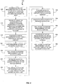
- FIG. 4 presents a flowchart representation of an embodiment of a method 100 of obtaining 3D surface data for a dental arch.
- the measurement results in a complete 3D data set that accurately represents the full arch of a patient, i.e., from the back molar on one side of the arch to the back molar on the opposite side of the arch.
- stitching errors and motion-induced errors can degrade the measurement results.
- a 3D measurement device that includes a 2D imager with a small measurement field of view (FOV) (e.g., 13 mm x 10 mm) relative to the full arch
- hundreds of 3D data sets may be stitched together to obtain the complete 3D data set for the arch.
- FOV field of view
- the method 100 numerous overlapping 3D data sets are stitched together in a common coordinate reference.
- the 3D data are obtained in a preferred manner or sequence so that the "finial" 3D data set resulting from all the 3D data more accurately represents the dental arch.
- a backbone 3D data set is first generated and additional sequences of 3D data are subsequently joined to the backbone 3D data set.
- Individual scan segments are used to acquire subsets of 3D data for the final point cloud. Limited motion of the wand during the 3D data acquisition for each scan segment results in reduced measurement error and increased measurement accuracy.
- a clinician performs the 3D measurement method 100 by positioning (step 105) the wand so that the structured light pattern illuminates a portion of an occlusal surface of the dental arch at a starting location, for example, at one end of the dental arch.
- 3D data are acquired for the illuminated portion of the occlusal surface.
- data acquisition starts by acquiring data from within a measurement field of view 86A at the patient's left back molar 90 of the upper dental arch as shown in FIG. 3 .
- the wand is then moved (step 110) from the patient's left back molar 90 along the arch to the right back molar while maintaining a substantially occlusal view.
- the motion of the wand is substantially in a direction parallel to the stripes or fringes of the structured light pattern.
- the primary motion of the wand during the occlusal scan is restricted substantially to a single plane.
- the occlusal view includes features having substantially higher spatial frequency content than other views.
- the occlusal view more readily shows rapidly varying structure (e.g., gaps between teeth) that improve the accuracy for stitching of 3D data relative to other scan views (i.e., buccal and lingual).
- the 3D data corresponding to the occlusal scan defines a backbone that can be used for attachment by other 3D data sets obtained during other directional scan views as necessary to obtain a complete set of 3D data for the arch.
- the clinician positions (step 115) the wand so that the structured light pattern illuminates a portion of the occlusal surface, for example, near or at one end of the arch, and 3D data are acquired that overlap a portion of the backbone 3D data set.
- the 3D measurement system provides an affirmative visual or audible indication to the clinician when the new 3D data for the real-time position of the structured light pattern "locks on" to the display of a point cloud for the backbone 3D data set.
- the newly-acquired 3D data are then registered or joined (step 120) to the backbone 3D data and serve as the start of a buccal scan segment for the arch.
- the wand is then rotated about its primary axis and moved (step 125) so that a portion of the buccal surface of the arch is illuminated with the structured light pattern and 3D data are acquired.
- the wand is then maneuvered (step 130) by the clinician so that the structured light pattern moves along a segment of the buccal surface.
- the wand may be moved so that the structured light pattern is scanned in time from the patient's back left molars to just beyond the midpoint of the buccal surface.
- FIGS. 6B show an occlusal view and a buccal view, respectively, of the position of the projection end 82 of the wand and the corresponding location of the measurement field of view (and structured light pattern) part way through this scan segment of the buccal surface.
- the clinician can rotate (step 135) the wand so that the structured light pattern illuminates the midpoint of the occlusal surface.
- the structured light pattern is used to acquire 3D data in an occlusal view that overlay data in the backbone 3D data set to more accurately "register" to the existing 3D data in the common coordinate reference system.
- a complementary buccal scan segment can now be performed.
- the clinician positions (step 140) the wand so that the structured light pattern illuminates a portion of the occlusal surface at the opposite end of the arch and 3D data are acquired that overlap a portion of the backbone 3D data set.
- the 3D data at this location are joined (step 145) to the 3D backbone data set and serve as the start of a complementary buccal scan segment for the arch.
- the wand is then rotated about its primary axis (step 150) so that a portion of remainder of the buccal surface of the arch is illuminated with the structured light pattern and 3D data are acquired.
- the wand is maneuvered (step 155) by the clinician so that the structured light pattern moves along the remainder of the buccal surface segment.
- the wand may be moved so that the structured light pattern is moved in time from the patient's back right molars to just beyond the midpoint of the buccal surface.
- the clinician can rotate (step 160) the wand so that the structured light pattern illuminates the midpoint region of the occlusal surface and 3D data are acquired in an occlusal view that overlay the data in the backbone 3D data set.
- the 3D data for this buccal segment are accurately registered in the common reference system of the backbone 3D data set.
- the clinician obtains 3D data for the lingual surface of the dental arch in a manner similar to that used for obtaining 3D data for the buccal surface. More specifically, steps 125 to steps 160 are performed by replacing all references to the buccal surface with references to the lingual surface. In total, five scan segments are performed to obtain a full set of 3D data for the final 3D data set for the dental arch.
- the steps of joining 3D data to the backbone 3D data set allows sequences of individual 3D images to be attached by referring to a subset of the chronologically ordered 3D images in the backbone 3D data set.
- This joining technique "primes the stitcher" so that the subsequent scan is properly registered to the backbone 3D data set and accurately shares the same global coordinate system.
- the order of scan segments can differ. For example, acquisition of the 3D data for the two lingual segments can precede acquisition of the 3D data for the buccal segments.
- the clinician can use a greater number of buccal and lingual scan segments and the extent of each segment can be smaller.
- the measurement system displays various portions of the backbone 3D data set to allow joining the backbone 3D data set at other locations.
- the structured light pattern and measurement field of view used for 3D data acquisition are moved along various surfaces of a dental arch and repositioned by manipulating the position and rotation of a wand.
- the method can be adapted for other types of 3D measurement systems.
- the method can be performed using a measurement field of view of a wand or maneuverable 3D measurement device that can be translated, rotated and positioned in a similar manner to the structured light pattern such that 3D data initially generated during the procedure can be used to generate a backbone 3D data set and subsequent 3D data can be joined to the backbone 3D data set to obtain a high accuracy 3D data representation of an object scene.
- the method preferably obtains 3D measurement data first for a directional view that substantially requires only two dimensional translation of the measurement field of view and in which high spatial frequency content is observable to create the backbone 3D data set and subsequent directional views are used to generate additional 3D data that can be attached to the backbone 3D data set.
Landscapes
- Health & Medical Sciences (AREA)
- Life Sciences & Earth Sciences (AREA)
- Physics & Mathematics (AREA)
- Engineering & Computer Science (AREA)
- General Physics & Mathematics (AREA)
- Veterinary Medicine (AREA)
- Public Health (AREA)
- General Health & Medical Sciences (AREA)
- Animal Behavior & Ethology (AREA)
- Medical Informatics (AREA)
- Pathology (AREA)
- Biomedical Technology (AREA)
- Heart & Thoracic Surgery (AREA)
- Oral & Maxillofacial Surgery (AREA)
- Molecular Biology (AREA)
- Surgery (AREA)
- Dentistry (AREA)
- Biophysics (AREA)
- Computer Vision & Pattern Recognition (AREA)
- Signal Processing (AREA)
- Multimedia (AREA)
- Audiology, Speech & Language Pathology (AREA)
- Optics & Photonics (AREA)
- Epidemiology (AREA)
- Nuclear Medicine, Radiotherapy & Molecular Imaging (AREA)
- Radiology & Medical Imaging (AREA)
- Dental Tools And Instruments Or Auxiliary Dental Instruments (AREA)
- Measurement Of The Respiration, Hearing Ability, Form, And Blood Characteristics Of Living Organisms (AREA)
- Endoscopes (AREA)
Claims (14)
- Verfahren zum Erlangen von dreidimensionalen (3D) Oberflächendaten einer Objektszene, wobei das Verfahren umfasst:Positionieren einer tragbaren 3D-Messvorrichtung (66) derart, dass ein Messungs-Sichtfeld einen ersten Abschnitt einer gerichteten Ansicht einer Objektszene an einem Anfangspunkt in der Objektszene aufweist, und Erfassen von 3D-Daten für das Messungs-Sichtfeld;Verschieben der tragbaren 3D-Messvorrichtung (66) während die gerichtete Ansicht einer Objektszene aufrecht erhalten wird, sodass das Messungs-Sichtfeld sich über eine verbleibende gerichtete Ansicht der Objektszene verschiebt, und die tragbare 3D-Messvorrichtung (66) 3D-Daten für das sich verschiebende Messungs-Sichtfeld erfasst, die mit den 3D-Daten für den Anfangspunkt in der Objektszene registriert werden, wobei die 3D-Daten für das positionierte und das verschobene Messungs-Sichtfeld einen Grundgerüst-3D-Datensatz definieren;Positionieren der tragbaren 3D-Messvorrichtung (66) derart, dass das Messungs-Sichtfeld einen zweiten Abschnitt der gerichteten Ansicht der Objektszene aufweist und die tragbare 3D-Messvorrichtung (66) 3D-Daten für das Messungs-Sichtfeld erfasst, die einen Teil des Grundgerüst-3D-Datensatzes überlappen;Verbinden der 3D-Daten, die den Teil des Grundgerüst-3D-Datensatzes überlappen mit dem Grundgerüst-3D-Datensatz; undManövrieren der tragbaren 3D-Messvorrichtung (66) derart, dass das Messungs-Sichtfeld einen Abschnitt einer orthogonal gerichteten Ansicht der Objektszene aufweist und die tragbare 3D-Messvorrichtung (66) 3D-Daten für das Messungs-Sichtfeld erfasst, die mit dem Grundgerüst-3D-Datensatz registriert werden.
- Verfahren nach Anspruch 1, weiter umfassend Manövrieren der tragbaren 3D-Messvorrichtung (66) derart, dass das Messungs-Sichtfeld über ein Segment der orthogonal gerichteten Ansicht der Objektszene abtastet und die tragbare 3D-Messvorrichtung (66) 3D-Daten für das Messungs-Sichtfeld erfasst, die mit dem Grundgerüst-3D-Datensatz registriert werden.
- Verfahren nach Anspruch 1, weiter umfassend Anzeigen der erfassten 3D-Daten zur Beobachtung.
- Verfahren nach Anspruch 3, wobei die erfassten 3D-Daten als eine 3D-Punktwolke angezeigt werden.
- Verfahren nach Anspruch 3, wobei die erfassten 3D-Daten als eine oder mehrere Objektoberflächen angezeigt werden.
- Verfahren nach Anspruch 1, wobei die Objektszene zumindest einen Abschnitt eines intraoralen Hohlraums umfasst.
- Verfahren nach Anspruch 1, wobei die tragbare 3D-Messvorrichtung (66) ein strukturiertes Lichtmuster (78) in die Objektszene projiziert, innerhalb des Messungs-Sichtfeldes.
- Verfahren nach Anspruch 7, wobei das strukturierte Lichtmuster (78) ein gestreiftes Muster umfasst.
- Verfahren nach Anspruch 7, wobei das strukturierte Lichtmuster (78) ein interferometrisches Intensitätsmuster umfasst.
- Verfahren nach Anspruch 7, wobei die gerichtete Ansicht der Objektszene eine okklusale Oberfläche eines Zahnbogens umfasst und wobei die orthogonal gerichtete Ansicht der Objektszene eine bukkale Oberfläche oder eine linguale Oberfläche des Zahnbogens umfasst.
- Verfahren nach Anspruch 1, wobei die die tragbare 3D-Messvorrichtung (66) sich während der Verschiebung der tragbaren 3D-Messvorrichtung (66) im Wesentlichen nicht dreht.
- Verfahren nach Anspruch 10, weiter umfassend Bewegen der tragbaren 3D-Messvorrichtung (66) derart, dass die Projektion des strukturierten Lichtmusters (78) über ein Segment der bukkalen oder der lingualen Oberfläche bewegt wird, um dadurch 3D-Daten für das Segment zu erfassen.
- Verfahren nach Anspruch 10, weiter umfassend Drehen der tragbaren 3D-Messvorrichtung (66) derart, dass die Projektion des strukturierten Lichtmusters (78) auf einen Abschnitt der okklusalen Oberfläche auftrifft, um dadurch 3D-Daten zu erfassen, die mit dem Grundgerüst-3D-Datensatz überlappen.
- Verfahren zum Erlangen von dreidimensionalen (3D) Oberflächendaten einer Objektszene nach Anspruch 1, bei dem die Objektszene ein intraoraler Hohlraum ist, und umfassend:Positionieren der tragbaren 3D-Messvorrichtung (66) in einem intraoralen Hohlraum derart, dass ein Messungs-Sichtfeld der tragbaren 3D-Messvorrichtung (66) einen Abschnitt einer okklusalen Oberfläche eines Zahnbogens an einem Anfangspunkt aufweist und Erfassen von 3D-Daten für das Messungs-Sichtfeld;wobei das Verschieben der tragbaren 3D-Messvorrichtung (66) derart erfolgt, dass das Messungs-Sichtfeld eine verbleibende okklusale Oberfläche des Zahnbogens aufweist und 3D-Daten, die für das sich verschiebende Messungs-Sichtfeld erfasst werden, mit den 3D-Daten für den Abschnitt der okklusalen Oberfläche registriert werden, wobei die 3D-Daten für den Abschnitt und die verbleibende okklusale Oberfläche einen Grundgerüst-3D-Datensatz für den Zahnbogen definieren;Positionieren der tragbaren 3D-Messvorrichtung (66) derart, dass das Messungs-Sichtfeld einen Abschnitt der okklusalen Oberfläche aufweist, um dadurch 3D-Daten zu erfassen, die einen Abschnitt des Grundgerüst-3D-Datensatzes überlappen;Verbinden der 3D-Daten, die einen Abschnitt des Grundgerüst-3D-Datensatzes überlappen mit dem Grundgerüst-3D-Datensatz; undwobei das Bewegen der tragbaren 3D-Messvorrichtung (66) derart erfolgt, dass das Messungs-Sichtfeld einen Abschnitt eines intraoralen Hohlraums aufweist, der von der okklusalen Oberfläche des Zahnbogens getrennt ist, um dadurch 3D-Daten für den Abschnitt des intraoralen Hohlraums zu erfassen, die mit dem Grundgerüst-3D-Datensatz registriert werden.
Applications Claiming Priority (2)
| Application Number | Priority Date | Filing Date | Title |
|---|---|---|---|
| US38173110P | 2010-09-10 | 2010-09-10 | |
| US13/217,595 US9157733B2 (en) | 2010-09-10 | 2011-08-25 | Method of data acquisition for three-dimensional imaging |
Publications (2)
| Publication Number | Publication Date |
|---|---|
| EP2428162A1 EP2428162A1 (de) | 2012-03-14 |
| EP2428162B1 true EP2428162B1 (de) | 2017-08-23 |
Family
ID=45093312
Family Applications (1)
| Application Number | Title | Priority Date | Filing Date |
|---|---|---|---|
| EP11179796.5A Active EP2428162B1 (de) | 2010-09-10 | 2011-09-02 | Verfahren zur Datenerfassung zur dreidimensionalen Abbildung der Mundhöle |
Country Status (4)
| Country | Link |
|---|---|
| US (2) | US9157733B2 (de) |
| EP (1) | EP2428162B1 (de) |
| JP (1) | JP5564477B2 (de) |
| CN (1) | CN102397113B (de) |
Cited By (15)
| Publication number | Priority date | Publication date | Assignee | Title |
|---|---|---|---|---|
| US11311252B2 (en) | 2018-08-09 | 2022-04-26 | Covidien Lp | Video-based patient monitoring systems and associated methods for detecting and monitoring breathing |
| US11484208B2 (en) | 2020-01-31 | 2022-11-01 | Covidien Lp | Attached sensor activation of additionally-streamed physiological parameters from non-contact monitoring systems and associated devices, systems, and methods |
| US11684287B2 (en) | 2016-02-19 | 2023-06-27 | Covidien Lp | System and methods for video-based monitoring of vital signs |
| US11776146B2 (en) | 2019-01-28 | 2023-10-03 | Covidien Lp | Edge handling methods for associated depth sensing camera devices, systems, and methods |
| US12121342B2 (en) | 2018-12-14 | 2024-10-22 | Covidien Lp | Depth sensing visualization modes for non-contact monitoring |
| US12156724B2 (en) | 2018-06-15 | 2024-12-03 | Covidien Lp | Systems and methods for video-based patient monitoring during surgery |
| US12303235B2 (en) | 2017-11-13 | 2025-05-20 | Covidien Lp | Systems and methods for video-based monitoring of a patient |
| US12329511B2 (en) | 2018-01-08 | 2025-06-17 | Covidien Lp | Systems and methods for video-based non-contact tidal volume monitoring |
| US12357194B2 (en) | 2020-07-09 | 2025-07-15 | Covidien Lp | Informative display for non-contact patient monitoring |
| US12374128B2 (en) | 2021-12-21 | 2025-07-29 | Covidien Lp | Non-contact depth sensing monitoring in vehicles |
| US12390124B2 (en) | 2021-01-27 | 2025-08-19 | Covidien Lp | Systems and methods for non-contact respiratory monitoring |
| US12482557B2 (en) | 2021-12-09 | 2025-11-25 | Covidien Lp | Systems and methods for improved non-contact patient monitoring of incubated neonates |
| US12490904B2 (en) | 2021-10-08 | 2025-12-09 | Covidien Lp | Enhanced image for non-contact monitoring |
| US12514468B2 (en) | 2020-12-02 | 2026-01-06 | Covidien Lp | Patient position monitoring methods and systems |
| US12635938B2 (en) | 2022-12-07 | 2026-05-26 | Covidien Lp | Monitoring for sleep apnea using non-contact monitoring system and pulse oximetry system |
Families Citing this family (33)
| Publication number | Priority date | Publication date | Assignee | Title |
|---|---|---|---|---|
| US20130323671A1 (en) * | 2012-05-30 | 2013-12-05 | Ormco Corporation | Spectral filter for an intra-oral imaging system |
| DE102012214467B4 (de) * | 2012-08-14 | 2019-08-08 | Sirona Dental Systems Gmbh | Verfahren zur Registrierung von einzelnen dreidimensionalen optischen Aufnahmen eines dentalen Objekts |
| JP6198857B2 (ja) * | 2013-03-11 | 2017-09-20 | ケアストリーム ヘルス インク | 3次元の画像形成を行うための方法及びシステム |
| US10278584B2 (en) | 2013-03-11 | 2019-05-07 | Carestream Dental Technology Topco Limited | Method and system for three-dimensional imaging |
| US9355454B2 (en) * | 2013-03-28 | 2016-05-31 | General Electric Company | Automatic estimation of anatomical extents |
| US9984502B2 (en) | 2013-08-27 | 2018-05-29 | International Business Machines Corporation | Creating three dimensional models with acceleration data |
| DE102014207667A1 (de) | 2014-04-23 | 2015-10-29 | Sirona Dental Systems Gmbh | Verfahren zur Durchführung einer optischen dreidimensionalen Aufnahme |
| JP6366546B2 (ja) * | 2015-07-13 | 2018-08-01 | 株式会社モリタ製作所 | 口腔内三次元計測装置、口腔内三次元計測方法及び口腔内三次元計測結果の表示方法 |
| JP6847404B2 (ja) * | 2015-12-24 | 2021-03-24 | 株式会社モリタ製作所 | 三次元計測方法及び三次元計測装置 |
| US10410430B2 (en) * | 2016-02-12 | 2019-09-10 | 3M Innovative Properties Company | Synchronization and animation of views showing digital 3D models of teeth |
| WO2017144934A1 (en) * | 2016-02-26 | 2017-08-31 | Trophy | Guided surgery apparatus and method |
| CN105996961B (zh) * | 2016-04-27 | 2018-05-11 | 安翰光电技术(武汉)有限公司 | 基于结构光的3d立体成像胶囊内窥镜系统及方法 |
| US10842383B2 (en) * | 2016-05-10 | 2020-11-24 | Masaki KAMBARA | Dental health assessment assisting apparatus and dental health assessment assisting system |
| CN106910213B (zh) * | 2017-01-23 | 2019-09-03 | 四川大学 | 一种基于计算成像的光学不可视场景三维信息获取方法 |
| US20200197136A1 (en) * | 2017-08-17 | 2020-06-25 | Trophy | Stencil for intraoral surface scanning |
| US10855973B1 (en) * | 2017-12-21 | 2020-12-01 | Facebook Technologies, Llc | Depth mapping using fringe interferometry |
| CN108303708B (zh) * | 2018-01-03 | 2022-07-29 | 京东方科技集团股份有限公司 | 三维重建系统及方法、移动设备、护眼方法、ar设备 |
| ES3037621T3 (en) | 2018-07-19 | 2025-10-03 | Activ Surgical Inc | Systems and methods for multi-modal sensing of depth in vision systems for automated surgical robots |
| CN109009510A (zh) * | 2018-08-15 | 2018-12-18 | 大连交通大学 | 牙齿咬合应力分布显示装置及方法 |
| US12121964B2 (en) | 2018-11-07 | 2024-10-22 | James J. Myrick | Processes, compositions and systems for 2D and 3D printing |
| TWI704907B (zh) * | 2018-11-29 | 2020-09-21 | 財團法人金屬工業研究發展中心 | 牙體建模裝置以及牙體建模方法 |
| EP3903165A4 (de) | 2018-12-28 | 2023-01-25 | Activ Surgical, Inc. | Systeme und verfahren zur optimierung der erreichbarkeit, des arbeitsplatzes und der geschicklichkeit in der minimalinvasiven chirurgie |
| CA3125166A1 (en) | 2018-12-28 | 2020-07-02 | Activ Surgical, Inc. | User interface elements for orientation of remote camera during surgery |
| US12292564B2 (en) | 2019-04-08 | 2025-05-06 | Activ Surgical, Inc. | Systems and methods for medical imaging |
| CN113950279B (zh) | 2019-04-08 | 2023-04-14 | 艾科缇弗外科公司 | 用于医疗成像的系统和方法 |
| WO2020214821A1 (en) | 2019-04-19 | 2020-10-22 | Activ Surgical, Inc. | Systems and methods for trocar kinematics |
| CN110251260B (zh) * | 2019-06-28 | 2022-05-17 | 苏州佳世达光电有限公司 | 口腔扫描机 |
| KR102161452B1 (ko) * | 2019-07-24 | 2020-10-05 | (주)칼리온 | 스캐너 움직임에 따른 모션 유효성 검출 장치 및 그 방법 |
| CN114599263A (zh) | 2019-08-21 | 2022-06-07 | 艾科缇弗外科公司 | 用于医疗成像的系统和方法 |
| US12076200B2 (en) * | 2019-11-12 | 2024-09-03 | Align Technology, Inc. | Digital 3D models of dental arches with accurate arch width |
| CN111947601B (zh) * | 2020-08-12 | 2021-11-12 | 上海科技大学 | 一种灰度伪随机编码结构光条纹的投影解算方法 |
| CN112932696B (zh) * | 2021-01-21 | 2023-04-07 | 上海埃蒙迪材料科技股份有限公司 | 牙齿特征点的计算方法、装置及电子设备 |
| CN118304025B (zh) * | 2024-06-06 | 2025-04-29 | 先临三维科技股份有限公司 | 一种扫描杆的扫描方法、系统及存储介质 |
Family Cites Families (21)
| Publication number | Priority date | Publication date | Assignee | Title |
|---|---|---|---|---|
| DE59008269D1 (de) * | 1990-03-13 | 1995-02-23 | Comdent Gmbh | Verfahren zur ausmessung eines raumes, insbesondere eines mundinnenraums sowie vorrichtung zur durchführung eines solchen verfahrens. |
| US5545039A (en) | 1990-04-10 | 1996-08-13 | Mushabac; David R. | Method and apparatus for preparing tooth or modifying dental restoration |
| US5870191A (en) | 1996-02-12 | 1999-02-09 | Massachusetts Institute Of Technology | Apparatus and methods for surface contour measurement |
| US6217334B1 (en) | 1997-01-28 | 2001-04-17 | Iris Development Corporation | Dental scanning method and apparatus |
| US6532299B1 (en) * | 2000-04-28 | 2003-03-11 | Orametrix, Inc. | System and method for mapping a surface |
| US6648640B2 (en) * | 1999-11-30 | 2003-11-18 | Ora Metrix, Inc. | Interactive orthodontic care system based on intra-oral scanning of teeth |
| AU2607301A (en) * | 1999-12-29 | 2001-07-09 | Ormco Corporation | Custom orthodontic appliance forming method and apparatus |
| US6386867B1 (en) | 2000-11-30 | 2002-05-14 | Duane Milford Durbin | Method and system for imaging and modeling dental structures |
| US6925198B2 (en) * | 2002-05-24 | 2005-08-02 | Ronald S. Scharlack | Method and system for three-dimensional modeling of object fields |
| US6821116B2 (en) | 2001-09-12 | 2004-11-23 | Ivoclar Vivadent, Inc. | System for scanning oral environment |
| US6993177B1 (en) * | 2001-11-02 | 2006-01-31 | Cognex Technology And Investment Corporation | Gauging based on global alignment and sub-models |
| EP1663046A4 (de) * | 2003-09-17 | 2011-10-05 | D4D Technologies Llc | Dreidimensionale hochgeschwindigkeits-multileitungs-digitalisierung |
| US7698068B2 (en) * | 2004-06-17 | 2010-04-13 | Cadent Ltd. | Method for providing data associated with the intraoral cavity |
| US7494338B2 (en) * | 2005-01-11 | 2009-02-24 | Duane Durbin | 3D dental scanner |
| JP5154955B2 (ja) * | 2005-03-03 | 2013-02-27 | カデント・リミテツド | 口腔スキャニング用システムおよび方法 |
| US7672504B2 (en) | 2005-09-01 | 2010-03-02 | Childers Edwin M C | Method and system for obtaining high resolution 3-D images of moving objects by use of sensor fusion |
| JP2008194108A (ja) | 2007-02-09 | 2008-08-28 | Shiyoufuu:Kk | 位置方向検出機能付き3次元上特性測定・表示装置 |
| DE102007060263A1 (de) | 2007-08-16 | 2009-02-26 | Steinbichler Optotechnik Gmbh | Vorrichtung zur Ermittlung der 3D-Koordinaten eines Objekts, insbesondere eines Zahns |
| EP2240115B1 (de) | 2007-12-21 | 2019-05-29 | 3M Innovative Properties Company | Auf verkleinerten bildern basierende überwachung kieferorthopädischer behandlungen |
| US8922780B2 (en) * | 2009-05-14 | 2014-12-30 | Andover Photonics, Inc. | Shape measurement using microchip based fringe projection |
| EP2312268A1 (de) | 2009-10-16 | 2011-04-20 | Straumann Holding AG | Abtastgerät zum Abtasten von dentalen Objekten und Verfahren zum Abtasten von dentalen Objekten |
-
2011
- 2011-08-25 US US13/217,595 patent/US9157733B2/en active Active
- 2011-09-02 EP EP11179796.5A patent/EP2428162B1/de active Active
- 2011-09-08 JP JP2011195641A patent/JP5564477B2/ja active Active
- 2011-09-09 CN CN201110273932.XA patent/CN102397113B/zh active Active
-
2015
- 2015-08-31 US US14/840,445 patent/US9955872B2/en active Active
Non-Patent Citations (1)
| Title |
|---|
| None * |
Cited By (22)
| Publication number | Priority date | Publication date | Assignee | Title |
|---|---|---|---|---|
| US12207916B2 (en) | 2016-02-19 | 2025-01-28 | Covidien Lp | System and methods for video-based monitoring of vital signs |
| US12502097B2 (en) | 2016-02-19 | 2025-12-23 | Covidien Lp | Systems and methods for video-based monitoring of vital signs |
| US11684287B2 (en) | 2016-02-19 | 2023-06-27 | Covidien Lp | System and methods for video-based monitoring of vital signs |
| US12016674B2 (en) | 2016-02-19 | 2024-06-25 | Covidien Lp | Systems and methods for video-based monitoring of vital signs |
| US12303235B2 (en) | 2017-11-13 | 2025-05-20 | Covidien Lp | Systems and methods for video-based monitoring of a patient |
| US12329511B2 (en) | 2018-01-08 | 2025-06-17 | Covidien Lp | Systems and methods for video-based non-contact tidal volume monitoring |
| US12207909B2 (en) | 2018-06-15 | 2025-01-28 | Covidien Lp | Systems and methods for video-based patient monitoring during surgery |
| US12156724B2 (en) | 2018-06-15 | 2024-12-03 | Covidien Lp | Systems and methods for video-based patient monitoring during surgery |
| US12016655B2 (en) | 2018-08-09 | 2024-06-25 | Covidien Lp | Video-based patient monitoring systems and associated methods for detecting and monitoring breathing |
| US11311252B2 (en) | 2018-08-09 | 2022-04-26 | Covidien Lp | Video-based patient monitoring systems and associated methods for detecting and monitoring breathing |
| US12678051B2 (en) | 2018-08-09 | 2026-07-14 | Covidien Lp | Video-based patient monitoring systems and associated methods for detecting and monitoring breathing |
| US12121342B2 (en) | 2018-12-14 | 2024-10-22 | Covidien Lp | Depth sensing visualization modes for non-contact monitoring |
| US11776146B2 (en) | 2019-01-28 | 2023-10-03 | Covidien Lp | Edge handling methods for associated depth sensing camera devices, systems, and methods |
| US12541867B2 (en) | 2019-01-28 | 2026-02-03 | Covidien Lp | Edge handling methods for associated depth sensing camera devices, systems, and methods |
| US11484208B2 (en) | 2020-01-31 | 2022-11-01 | Covidien Lp | Attached sensor activation of additionally-streamed physiological parameters from non-contact monitoring systems and associated devices, systems, and methods |
| US12357194B2 (en) | 2020-07-09 | 2025-07-15 | Covidien Lp | Informative display for non-contact patient monitoring |
| US12514468B2 (en) | 2020-12-02 | 2026-01-06 | Covidien Lp | Patient position monitoring methods and systems |
| US12390124B2 (en) | 2021-01-27 | 2025-08-19 | Covidien Lp | Systems and methods for non-contact respiratory monitoring |
| US12490904B2 (en) | 2021-10-08 | 2025-12-09 | Covidien Lp | Enhanced image for non-contact monitoring |
| US12482557B2 (en) | 2021-12-09 | 2025-11-25 | Covidien Lp | Systems and methods for improved non-contact patient monitoring of incubated neonates |
| US12374128B2 (en) | 2021-12-21 | 2025-07-29 | Covidien Lp | Non-contact depth sensing monitoring in vehicles |
| US12635938B2 (en) | 2022-12-07 | 2026-05-26 | Covidien Lp | Monitoring for sleep apnea using non-contact monitoring system and pulse oximetry system |
Also Published As
| Publication number | Publication date |
|---|---|
| JP2012066072A (ja) | 2012-04-05 |
| CN102397113A (zh) | 2012-04-04 |
| US20150366457A1 (en) | 2015-12-24 |
| EP2428162A1 (de) | 2012-03-14 |
| US9955872B2 (en) | 2018-05-01 |
| JP5564477B2 (ja) | 2014-07-30 |
| US20120062701A1 (en) | 2012-03-15 |
| CN102397113B (zh) | 2015-09-02 |
| US9157733B2 (en) | 2015-10-13 |
Similar Documents
| Publication | Publication Date | Title |
|---|---|---|
| US9157733B2 (en) | Method of data acquisition for three-dimensional imaging | |
| US11105616B2 (en) | Intraoral scanner with diagonal focal plane | |
| US7573583B2 (en) | Laser digitizer system for dental applications | |
| EP2428764A1 (de) | Systeme und Verfahren zur Verarbeitung und Anzeige intraoraler Messdaten | |
| EP2428913B1 (de) | Objektklassifizierung für gemessene dreidimensionale Objektszenen | |
| JP5583761B2 (ja) | 動的基準フレームを用いた3次元表面検出方法及び装置 | |
| EP2732434B1 (de) | Erkennung eines beweglichen objekts bei der 3d-abtastung eines starren körpers | |
| JP6293122B2 (ja) | 歯の状況の測定方法 | |
| JP2002022424A (ja) | 3次元測定装置 | |
| DK2428162T3 (en) | Method of recording data for three-dimensional imaging of intra-oral cavities | |
| CN111787827A (zh) | 用于口内表面扫描的模版 | |
| HK1164090A (en) | Method of data acquisition for three-dimensional imaging of the intra-oral cavity | |
| HK1164432A (en) | System and method for processing and displaying intra-oral measurement data | |
| HK1164507A (en) | Object classification for measured three-dimensional object scenes |
Legal Events
| Date | Code | Title | Description |
|---|---|---|---|
| AK | Designated contracting states |
Kind code of ref document: A1 Designated state(s): AL AT BE BG CH CY CZ DE DK EE ES FI FR GB GR HR HU IE IS IT LI LT LU LV MC MK MT NL NO PL PT RO RS SE SI SK SM TR |
|
| AX | Request for extension of the european patent |
Extension state: BA ME |
|
| PUAI | Public reference made under article 153(3) epc to a published international application that has entered the european phase |
Free format text: ORIGINAL CODE: 0009012 |
|
| REG | Reference to a national code |
Ref country code: HK Ref legal event code: DE Ref document number: 1164090 Country of ref document: HK |
|
| 17P | Request for examination filed |
Effective date: 20120911 |
|
| REG | Reference to a national code |
Ref country code: DE Ref legal event code: R079 Ref document number: 602011040789 Country of ref document: DE Free format text: PREVIOUS MAIN CLASS: A61B0005107000 Ipc: G03B0035100000 |
|
| RIC1 | Information provided on ipc code assigned before grant |
Ipc: A61B 5/107 20060101ALI20170215BHEP Ipc: G03B 37/02 20060101ALI20170215BHEP Ipc: G01B 11/24 20060101ALI20170215BHEP Ipc: A61C 9/00 20060101ALI20170215BHEP Ipc: A61B 5/00 20060101ALI20170215BHEP Ipc: G01B 11/25 20060101ALI20170215BHEP Ipc: H04N 13/02 20060101ALI20170215BHEP Ipc: G03B 35/10 20060101AFI20170215BHEP |
|
| GRAP | Despatch of communication of intention to grant a patent |
Free format text: ORIGINAL CODE: EPIDOSNIGR1 |
|
| STAA | Information on the status of an ep patent application or granted ep patent |
Free format text: STATUS: GRANT OF PATENT IS INTENDED |
|
| INTG | Intention to grant announced |
Effective date: 20170324 |
|
| GRAS | Grant fee paid |
Free format text: ORIGINAL CODE: EPIDOSNIGR3 |
|
| GRAA | (expected) grant |
Free format text: ORIGINAL CODE: 0009210 |
|
| STAA | Information on the status of an ep patent application or granted ep patent |
Free format text: STATUS: THE PATENT HAS BEEN GRANTED |
|
| AK | Designated contracting states |
Kind code of ref document: B1 Designated state(s): AL AT BE BG CH CY CZ DE DK EE ES FI FR GB GR HR HU IE IS IT LI LT LU LV MC MK MT NL NO PL PT RO RS SE SI SK SM TR |
|
| REG | Reference to a national code |
Ref country code: GB Ref legal event code: FG4D |
|
| REG | Reference to a national code |
Ref country code: CH Ref legal event code: EP |
|
| REG | Reference to a national code |
Ref country code: AT Ref legal event code: REF Ref document number: 921978 Country of ref document: AT Kind code of ref document: T Effective date: 20170915 |
|
| REG | Reference to a national code |
Ref country code: IE Ref legal event code: FG4D |
|
| REG | Reference to a national code |
Ref country code: FR Ref legal event code: PLFP Year of fee payment: 7 |
|
| REG | Reference to a national code |
Ref country code: DK Ref legal event code: T3 Effective date: 20170928 |
|
| REG | Reference to a national code |
Ref country code: DE Ref legal event code: R096 Ref document number: 602011040789 Country of ref document: DE |
|
| REG | Reference to a national code |
Ref country code: NL Ref legal event code: MP Effective date: 20170823 |
|
| REG | Reference to a national code |
Ref country code: LT Ref legal event code: MG4D |
|
| REG | Reference to a national code |
Ref country code: AT Ref legal event code: MK05 Ref document number: 921978 Country of ref document: AT Kind code of ref document: T Effective date: 20170823 |
|
| PG25 | Lapsed in a contracting state [announced via postgrant information from national office to epo] |
Ref country code: NO Free format text: LAPSE BECAUSE OF FAILURE TO SUBMIT A TRANSLATION OF THE DESCRIPTION OR TO PAY THE FEE WITHIN THE PRESCRIBED TIME-LIMIT Effective date: 20171123 Ref country code: HR Free format text: LAPSE BECAUSE OF FAILURE TO SUBMIT A TRANSLATION OF THE DESCRIPTION OR TO PAY THE FEE WITHIN THE PRESCRIBED TIME-LIMIT Effective date: 20170823 Ref country code: FI Free format text: LAPSE BECAUSE OF FAILURE TO SUBMIT A TRANSLATION OF THE DESCRIPTION OR TO PAY THE FEE WITHIN THE PRESCRIBED TIME-LIMIT Effective date: 20170823 Ref country code: AT Free format text: LAPSE BECAUSE OF FAILURE TO SUBMIT A TRANSLATION OF THE DESCRIPTION OR TO PAY THE FEE WITHIN THE PRESCRIBED TIME-LIMIT Effective date: 20170823 Ref country code: SE Free format text: LAPSE BECAUSE OF FAILURE TO SUBMIT A TRANSLATION OF THE DESCRIPTION OR TO PAY THE FEE WITHIN THE PRESCRIBED TIME-LIMIT Effective date: 20170823 Ref country code: NL Free format text: LAPSE BECAUSE OF FAILURE TO SUBMIT A TRANSLATION OF THE DESCRIPTION OR TO PAY THE FEE WITHIN THE PRESCRIBED TIME-LIMIT Effective date: 20170823 Ref country code: LT Free format text: LAPSE BECAUSE OF FAILURE TO SUBMIT A TRANSLATION OF THE DESCRIPTION OR TO PAY THE FEE WITHIN THE PRESCRIBED TIME-LIMIT Effective date: 20170823 |
|
| PG25 | Lapsed in a contracting state [announced via postgrant information from national office to epo] |
Ref country code: ES Free format text: LAPSE BECAUSE OF FAILURE TO SUBMIT A TRANSLATION OF THE DESCRIPTION OR TO PAY THE FEE WITHIN THE PRESCRIBED TIME-LIMIT Effective date: 20170823 Ref country code: LV Free format text: LAPSE BECAUSE OF FAILURE TO SUBMIT A TRANSLATION OF THE DESCRIPTION OR TO PAY THE FEE WITHIN THE PRESCRIBED TIME-LIMIT Effective date: 20170823 Ref country code: BG Free format text: LAPSE BECAUSE OF FAILURE TO SUBMIT A TRANSLATION OF THE DESCRIPTION OR TO PAY THE FEE WITHIN THE PRESCRIBED TIME-LIMIT Effective date: 20171123 Ref country code: IS Free format text: LAPSE BECAUSE OF FAILURE TO SUBMIT A TRANSLATION OF THE DESCRIPTION OR TO PAY THE FEE WITHIN THE PRESCRIBED TIME-LIMIT Effective date: 20171223 Ref country code: PL Free format text: LAPSE BECAUSE OF FAILURE TO SUBMIT A TRANSLATION OF THE DESCRIPTION OR TO PAY THE FEE WITHIN THE PRESCRIBED TIME-LIMIT Effective date: 20170823 Ref country code: RS Free format text: LAPSE BECAUSE OF FAILURE TO SUBMIT A TRANSLATION OF THE DESCRIPTION OR TO PAY THE FEE WITHIN THE PRESCRIBED TIME-LIMIT Effective date: 20170823 Ref country code: GR Free format text: LAPSE BECAUSE OF FAILURE TO SUBMIT A TRANSLATION OF THE DESCRIPTION OR TO PAY THE FEE WITHIN THE PRESCRIBED TIME-LIMIT Effective date: 20171124 |
|
| PG25 | Lapsed in a contracting state [announced via postgrant information from national office to epo] |
Ref country code: CZ Free format text: LAPSE BECAUSE OF FAILURE TO SUBMIT A TRANSLATION OF THE DESCRIPTION OR TO PAY THE FEE WITHIN THE PRESCRIBED TIME-LIMIT Effective date: 20170823 Ref country code: RO Free format text: LAPSE BECAUSE OF FAILURE TO SUBMIT A TRANSLATION OF THE DESCRIPTION OR TO PAY THE FEE WITHIN THE PRESCRIBED TIME-LIMIT Effective date: 20170823 |
|
| REG | Reference to a national code |
Ref country code: CH Ref legal event code: PL |
|
| RAP2 | Party data changed (patent owner data changed or rights of a patent transferred) |
Owner name: DENTAL IMAGING TECHNOLOGIES CORPORATION |
|
| REG | Reference to a national code |
Ref country code: DE Ref legal event code: R097 Ref document number: 602011040789 Country of ref document: DE |
|
| PG25 | Lapsed in a contracting state [announced via postgrant information from national office to epo] |
Ref country code: SK Free format text: LAPSE BECAUSE OF FAILURE TO SUBMIT A TRANSLATION OF THE DESCRIPTION OR TO PAY THE FEE WITHIN THE PRESCRIBED TIME-LIMIT Effective date: 20170823 Ref country code: SM Free format text: LAPSE BECAUSE OF FAILURE TO SUBMIT A TRANSLATION OF THE DESCRIPTION OR TO PAY THE FEE WITHIN THE PRESCRIBED TIME-LIMIT Effective date: 20170823 Ref country code: EE Free format text: LAPSE BECAUSE OF FAILURE TO SUBMIT A TRANSLATION OF THE DESCRIPTION OR TO PAY THE FEE WITHIN THE PRESCRIBED TIME-LIMIT Effective date: 20170823 Ref country code: MC Free format text: LAPSE BECAUSE OF FAILURE TO SUBMIT A TRANSLATION OF THE DESCRIPTION OR TO PAY THE FEE WITHIN THE PRESCRIBED TIME-LIMIT Effective date: 20170823 |
|
| REG | Reference to a national code |
Ref country code: IE Ref legal event code: MM4A |
|
| REG | Reference to a national code |
Ref country code: BE Ref legal event code: MM Effective date: 20170930 |
|
| PG25 | Lapsed in a contracting state [announced via postgrant information from national office to epo] |
Ref country code: LU Free format text: LAPSE BECAUSE OF NON-PAYMENT OF DUE FEES Effective date: 20170902 |
|
| PLBE | No opposition filed within time limit |
Free format text: ORIGINAL CODE: 0009261 |
|
| STAA | Information on the status of an ep patent application or granted ep patent |
Free format text: STATUS: NO OPPOSITION FILED WITHIN TIME LIMIT |
|
| RAP2 | Party data changed (patent owner data changed or rights of a patent transferred) |
Owner name: DENTAL IMAGING TECHNOLOGIES CORPORATION |
|
| GBPC | Gb: european patent ceased through non-payment of renewal fee |
Effective date: 20171123 |
|
| PG25 | Lapsed in a contracting state [announced via postgrant information from national office to epo] |
Ref country code: CH Free format text: LAPSE BECAUSE OF NON-PAYMENT OF DUE FEES Effective date: 20170930 Ref country code: LI Free format text: LAPSE BECAUSE OF NON-PAYMENT OF DUE FEES Effective date: 20170930 Ref country code: IE Free format text: LAPSE BECAUSE OF NON-PAYMENT OF DUE FEES Effective date: 20170902 |
|
| 26N | No opposition filed |
Effective date: 20180524 |
|
| PG25 | Lapsed in a contracting state [announced via postgrant information from national office to epo] |
Ref country code: SI Free format text: LAPSE BECAUSE OF FAILURE TO SUBMIT A TRANSLATION OF THE DESCRIPTION OR TO PAY THE FEE WITHIN THE PRESCRIBED TIME-LIMIT Effective date: 20170823 Ref country code: BE Free format text: LAPSE BECAUSE OF NON-PAYMENT OF DUE FEES Effective date: 20170930 |
|
| REG | Reference to a national code |
Ref country code: FR Ref legal event code: PLFP Year of fee payment: 8 |
|
| PG25 | Lapsed in a contracting state [announced via postgrant information from national office to epo] |
Ref country code: MT Free format text: LAPSE BECAUSE OF NON-PAYMENT OF DUE FEES Effective date: 20170902 |
|
| PG25 | Lapsed in a contracting state [announced via postgrant information from national office to epo] |
Ref country code: GB Free format text: LAPSE BECAUSE OF NON-PAYMENT OF DUE FEES Effective date: 20171123 |
|
| PG25 | Lapsed in a contracting state [announced via postgrant information from national office to epo] |
Ref country code: HU Free format text: LAPSE BECAUSE OF FAILURE TO SUBMIT A TRANSLATION OF THE DESCRIPTION OR TO PAY THE FEE WITHIN THE PRESCRIBED TIME-LIMIT; INVALID AB INITIO Effective date: 20110902 |
|
| PG25 | Lapsed in a contracting state [announced via postgrant information from national office to epo] |
Ref country code: CY Free format text: LAPSE BECAUSE OF NON-PAYMENT OF DUE FEES Effective date: 20170823 |
|
| PG25 | Lapsed in a contracting state [announced via postgrant information from national office to epo] |
Ref country code: MK Free format text: LAPSE BECAUSE OF FAILURE TO SUBMIT A TRANSLATION OF THE DESCRIPTION OR TO PAY THE FEE WITHIN THE PRESCRIBED TIME-LIMIT Effective date: 20170823 |
|
| PG25 | Lapsed in a contracting state [announced via postgrant information from national office to epo] |
Ref country code: TR Free format text: LAPSE BECAUSE OF FAILURE TO SUBMIT A TRANSLATION OF THE DESCRIPTION OR TO PAY THE FEE WITHIN THE PRESCRIBED TIME-LIMIT Effective date: 20170823 |
|
| PG25 | Lapsed in a contracting state [announced via postgrant information from national office to epo] |
Ref country code: PT Free format text: LAPSE BECAUSE OF FAILURE TO SUBMIT A TRANSLATION OF THE DESCRIPTION OR TO PAY THE FEE WITHIN THE PRESCRIBED TIME-LIMIT Effective date: 20170823 |
|
| PG25 | Lapsed in a contracting state [announced via postgrant information from national office to epo] |
Ref country code: AL Free format text: LAPSE BECAUSE OF FAILURE TO SUBMIT A TRANSLATION OF THE DESCRIPTION OR TO PAY THE FEE WITHIN THE PRESCRIBED TIME-LIMIT Effective date: 20170823 |
|
| P01 | Opt-out of the competence of the unified patent court (upc) registered |
Effective date: 20230525 |
|
| REG | Reference to a national code |
Ref country code: HK Ref legal event code: WD Ref document number: 1164090 Country of ref document: HK |
|
| PGFP | Annual fee paid to national office [announced via postgrant information from national office to epo] |
Ref country code: DK Payment date: 20250911 Year of fee payment: 15 Ref country code: DE Payment date: 20250702 Year of fee payment: 15 |
|
| PGFP | Annual fee paid to national office [announced via postgrant information from national office to epo] |
Ref country code: IT Payment date: 20250825 Year of fee payment: 15 |
|
| PGFP | Annual fee paid to national office [announced via postgrant information from national office to epo] |
Ref country code: FR Payment date: 20250703 Year of fee payment: 15 |