EP2425956B1 - Boîtier moulé par injection doté d'un motif d'antenne et son procédé de fabrication - Google Patents
Boîtier moulé par injection doté d'un motif d'antenne et son procédé de fabrication Download PDFInfo
- Publication number
- EP2425956B1 EP2425956B1 EP11179761.9A EP11179761A EP2425956B1 EP 2425956 B1 EP2425956 B1 EP 2425956B1 EP 11179761 A EP11179761 A EP 11179761A EP 2425956 B1 EP2425956 B1 EP 2425956B1
- Authority
- EP
- European Patent Office
- Prior art keywords
- antenna patterns
- injection
- fixing holes
- molded case
- antenna
- Prior art date
- Legal status (The legal status is an assumption and is not a legal conclusion. Google has not performed a legal analysis and makes no representation as to the accuracy of the status listed.)
- Not-in-force
Links
Images


Classifications
-
- B—PERFORMING OPERATIONS; TRANSPORTING
- B29—WORKING OF PLASTICS; WORKING OF SUBSTANCES IN A PLASTIC STATE IN GENERAL
- B29C—SHAPING OR JOINING OF PLASTICS; SHAPING OF MATERIAL IN A PLASTIC STATE, NOT OTHERWISE PROVIDED FOR; AFTER-TREATMENT OF THE SHAPED PRODUCTS, e.g. REPAIRING
- B29C45/00—Injection moulding, i.e. forcing the required volume of moulding material through a nozzle into a closed mould; Apparatus therefor
- B29C45/14—Injection moulding, i.e. forcing the required volume of moulding material through a nozzle into a closed mould; Apparatus therefor incorporating preformed parts or layers, e.g. injection moulding around inserts or for coating articles
- B29C45/14639—Injection moulding, i.e. forcing the required volume of moulding material through a nozzle into a closed mould; Apparatus therefor incorporating preformed parts or layers, e.g. injection moulding around inserts or for coating articles for obtaining an insulating effect, e.g. for electrical components
-
- B—PERFORMING OPERATIONS; TRANSPORTING
- B29—WORKING OF PLASTICS; WORKING OF SUBSTANCES IN A PLASTIC STATE IN GENERAL
- B29C—SHAPING OR JOINING OF PLASTICS; SHAPING OF MATERIAL IN A PLASTIC STATE, NOT OTHERWISE PROVIDED FOR; AFTER-TREATMENT OF THE SHAPED PRODUCTS, e.g. REPAIRING
- B29C45/00—Injection moulding, i.e. forcing the required volume of moulding material through a nozzle into a closed mould; Apparatus therefor
- B29C45/14—Injection moulding, i.e. forcing the required volume of moulding material through a nozzle into a closed mould; Apparatus therefor incorporating preformed parts or layers, e.g. injection moulding around inserts or for coating articles
- B29C45/14065—Positioning or centering articles in the mould
-
- H—ELECTRICITY
- H01—ELECTRIC ELEMENTS
- H01Q—ANTENNAS, i.e. RADIO AERIALS
- H01Q1/00—Details of, or arrangements associated with, antennas
- H01Q1/12—Supports; Mounting means
- H01Q1/22—Supports; Mounting means by structural association with other equipment or articles
- H01Q1/24—Supports; Mounting means by structural association with other equipment or articles with receiving set
- H01Q1/241—Supports; Mounting means by structural association with other equipment or articles with receiving set used in mobile communications, e.g. GSM
- H01Q1/242—Supports; Mounting means by structural association with other equipment or articles with receiving set used in mobile communications, e.g. GSM specially adapted for hand-held use
- H01Q1/243—Supports; Mounting means by structural association with other equipment or articles with receiving set used in mobile communications, e.g. GSM specially adapted for hand-held use with built-in antennas
-
- B—PERFORMING OPERATIONS; TRANSPORTING
- B29—WORKING OF PLASTICS; WORKING OF SUBSTANCES IN A PLASTIC STATE IN GENERAL
- B29C—SHAPING OR JOINING OF PLASTICS; SHAPING OF MATERIAL IN A PLASTIC STATE, NOT OTHERWISE PROVIDED FOR; AFTER-TREATMENT OF THE SHAPED PRODUCTS, e.g. REPAIRING
- B29C45/00—Injection moulding, i.e. forcing the required volume of moulding material through a nozzle into a closed mould; Apparatus therefor
- B29C45/14—Injection moulding, i.e. forcing the required volume of moulding material through a nozzle into a closed mould; Apparatus therefor incorporating preformed parts or layers, e.g. injection moulding around inserts or for coating articles
- B29C45/14311—Injection moulding, i.e. forcing the required volume of moulding material through a nozzle into a closed mould; Apparatus therefor incorporating preformed parts or layers, e.g. injection moulding around inserts or for coating articles using means for bonding the coating to the articles
- B29C2045/14327—Injection moulding, i.e. forcing the required volume of moulding material through a nozzle into a closed mould; Apparatus therefor incorporating preformed parts or layers, e.g. injection moulding around inserts or for coating articles using means for bonding the coating to the articles anchoring by forcing the material to pass through a hole in the article
-
- B—PERFORMING OPERATIONS; TRANSPORTING
- B29—WORKING OF PLASTICS; WORKING OF SUBSTANCES IN A PLASTIC STATE IN GENERAL
- B29C—SHAPING OR JOINING OF PLASTICS; SHAPING OF MATERIAL IN A PLASTIC STATE, NOT OTHERWISE PROVIDED FOR; AFTER-TREATMENT OF THE SHAPED PRODUCTS, e.g. REPAIRING
- B29C45/00—Injection moulding, i.e. forcing the required volume of moulding material through a nozzle into a closed mould; Apparatus therefor
- B29C45/0053—Injection moulding, i.e. forcing the required volume of moulding material through a nozzle into a closed mould; Apparatus therefor combined with a final operation, e.g. shaping
- B29C45/006—Joining parts moulded in separate cavities
-
- B—PERFORMING OPERATIONS; TRANSPORTING
- B29—WORKING OF PLASTICS; WORKING OF SUBSTANCES IN A PLASTIC STATE IN GENERAL
- B29C—SHAPING OR JOINING OF PLASTICS; SHAPING OF MATERIAL IN A PLASTIC STATE, NOT OTHERWISE PROVIDED FOR; AFTER-TREATMENT OF THE SHAPED PRODUCTS, e.g. REPAIRING
- B29C45/00—Injection moulding, i.e. forcing the required volume of moulding material through a nozzle into a closed mould; Apparatus therefor
- B29C45/14—Injection moulding, i.e. forcing the required volume of moulding material through a nozzle into a closed mould; Apparatus therefor incorporating preformed parts or layers, e.g. injection moulding around inserts or for coating articles
- B29C45/14311—Injection moulding, i.e. forcing the required volume of moulding material through a nozzle into a closed mould; Apparatus therefor incorporating preformed parts or layers, e.g. injection moulding around inserts or for coating articles using means for bonding the coating to the articles
-
- B—PERFORMING OPERATIONS; TRANSPORTING
- B29—WORKING OF PLASTICS; WORKING OF SUBSTANCES IN A PLASTIC STATE IN GENERAL
- B29C—SHAPING OR JOINING OF PLASTICS; SHAPING OF MATERIAL IN A PLASTIC STATE, NOT OTHERWISE PROVIDED FOR; AFTER-TREATMENT OF THE SHAPED PRODUCTS, e.g. REPAIRING
- B29C45/00—Injection moulding, i.e. forcing the required volume of moulding material through a nozzle into a closed mould; Apparatus therefor
- B29C45/14—Injection moulding, i.e. forcing the required volume of moulding material through a nozzle into a closed mould; Apparatus therefor incorporating preformed parts or layers, e.g. injection moulding around inserts or for coating articles
- B29C45/14778—Injection moulding, i.e. forcing the required volume of moulding material through a nozzle into a closed mould; Apparatus therefor incorporating preformed parts or layers, e.g. injection moulding around inserts or for coating articles the article consisting of a material with particular properties, e.g. porous, brittle
-
- B—PERFORMING OPERATIONS; TRANSPORTING
- B29—WORKING OF PLASTICS; WORKING OF SUBSTANCES IN A PLASTIC STATE IN GENERAL
- B29K—INDEXING SCHEME ASSOCIATED WITH SUBCLASSES B29B, B29C OR B29D, RELATING TO MOULDING MATERIALS OR TO MATERIALS FOR MOULDS, REINFORCEMENTS, FILLERS OR PREFORMED PARTS, e.g. INSERTS
- B29K2705/00—Use of metals, their alloys or their compounds, for preformed parts, e.g. for inserts
-
- B—PERFORMING OPERATIONS; TRANSPORTING
- B29—WORKING OF PLASTICS; WORKING OF SUBSTANCES IN A PLASTIC STATE IN GENERAL
- B29L—INDEXING SCHEME ASSOCIATED WITH SUBCLASS B29C, RELATING TO PARTICULAR ARTICLES
- B29L2031/00—Other particular articles
- B29L2031/34—Electrical apparatus, e.g. sparking plugs or parts thereof
- B29L2031/3431—Telephones, Earphones
-
- B—PERFORMING OPERATIONS; TRANSPORTING
- B29—WORKING OF PLASTICS; WORKING OF SUBSTANCES IN A PLASTIC STATE IN GENERAL
- B29L—INDEXING SCHEME ASSOCIATED WITH SUBCLASS B29C, RELATING TO PARTICULAR ARTICLES
- B29L2031/00—Other particular articles
- B29L2031/34—Electrical apparatus, e.g. sparking plugs or parts thereof
- B29L2031/3456—Antennas, e.g. radomes
-
- B—PERFORMING OPERATIONS; TRANSPORTING
- B29—WORKING OF PLASTICS; WORKING OF SUBSTANCES IN A PLASTIC STATE IN GENERAL
- B29L—INDEXING SCHEME ASSOCIATED WITH SUBCLASS B29C, RELATING TO PARTICULAR ARTICLES
- B29L2031/00—Other particular articles
- B29L2031/34—Electrical apparatus, e.g. sparking plugs or parts thereof
- B29L2031/3481—Housings or casings incorporating or embedding electric or electronic elements
Definitions
- the present invention relates to an injection-molded case and a manufacturing method thereof. More particularly, the present invention relates to an injection molded case and manufacturing method in which antenna patterns are formed in the injection-molded case.
- a portable communication device refers to a device with which a user performs wireless communications with another party.
- a portable communication device generally includes an HHP, a CT-2 cellular phone, a digital phone, a PCS phone, a PDA, etc., and can be further classified into various types of devices according to the appearance.
- a wireless terminal is classified into one of a bar-type, flip-type, folder-type, and slide-type of wireless terminals according to appearance.
- the above enumerated conventional portable communication devices are necessarily provided with an antenna device, a data input/output device, and a data transmitting/receiving device.
- the data input device a keypad through which data can be input mainly by a fmger-pressing operation is generally used.
- Portable communication devices have become smaller and lighter with each generation of devices. Accordingly, an antenna device applied to the portable communication device also has become smaller, and an internal antenna which can be embedded in the communication device has become the typical antenna used in such devices, whereas a few years back users had antennas physically extending from the portable communication device.
- a metallic sheet is cut by a press process to fabricate an antenna pattern 2a, and then as shown in FIG. 2 , the antenna pattern 2a is integratedly mounted in an injection-molded article 2b by a first-insert injection molding process.
- the injection-molded article 2b mounted with the antenna pattern 2a is integratedly mounted in the battery cover part 1 of the portable communication device by a second insert injection molding process.
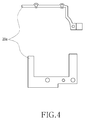
- a metallic sheet is cut by a press process in accordance with the shape of the portable communication device so as to fabricate an antenna pattern 20a, and then as shown in FIG. 5 , the antenna pattern 20a is integratedly mounted in an injection-molded article 20b by a first insert injection molding process.
- the injection-molded article 20b mounted with the antenna pattern 20a is integratedly mounted in the rear case 10 of the portable communication device by a second insert injection molding process.
- the mounting process is divided into two steps. In other words, the process is carried out by first and second insert injection molding processes.
- a conventional internal antenna device has a problem in that a manufacturing cost of a product is increased due to a complicated manufacturing process and an increase of a manufacturing time because an antenna pattern is fabricated by a press process and then is formed in an injection-molded article, a battery cover part, or a rear case of a communication device through first and second insert injection molding processes.
- US-2010/039347-A1 discloses a housing according to the preamble of claim 1, functioning as an antenna including an antenna base including two protruding flanges.
- the housing is formed by injection molding a molten plastic material over and around the antenna base, whereby the antenna base is embedded in the housing, and the protruding flanges are exposed out of the housing. A method for fabricating the housing is also described.
- US-2009/322629-A1 discloses a cover adapted to a communication device, a communication device including the same and a method for manufacturing the same.
- the cover according to the invention includes a cover body and an antenna.
- the cover body has a bottom surface.
- the antenna is fixed at a predetermined position on the bottom surface by an insert molding process.
- Embodiments of the present invention provide an injection-molded case having antenna patterns and the manufacturing method thereof, in which antenna patterns are formed in the injection-molded case by only one (i.e. single) insert injection molding process, unlike a conventional technology where antenna patterns are formed in an injection-molded case by first insert and second insert injection molding processes. Since an additional insert injection molding process is not required, the present invention reduces a manufacturing process and a manufacturing time of a product. Also, since it is not required to manufacture an additional (i.e. second) mold, it is possible to reduce a manufacturing cost of a product.
- an injection-molded case having one or more antenna patterns
- the injection-molded case comprising: one or more antenna patterns fabricated by a press process; and an injection-molded case having the antenna patterns provided therewithin, in which the injection molded case is fabricated by fixing the antenna patterns on an injection mold and performing single insert injection molding process; wherein each antenna pattern comprises one or more first fixing holes formed in the antenna pattern an arranged to fixedly couple with at least one of ribs or fixing protrusions formed on an injections mold, one or more second fixing holds formed at positions adjacent to the first fixing holes in the antenna patterns, in which the one or more second fixing holds are arranged to fixedly couple with ribs or fixing protrusions formed on the injection-molded case after the single insert injection molding process, and one or more third fixing holes formed with jaws arranged to receive an injected resin inserted into the jaws during the single insert injection molding process such that the resin rises in and over the jaws of the third fixing holes so as to fix the
- a method according to claim 5 for manufacturing an injection-molded case having one or more antenna patterns comprising the steps of: fabricating one or more antenna patterns fabricated by a press process; and fabricating an injection-molded case having the antenna patterns provided therewithin by fixing the antenna patterns on an injection mold and performing a single insert injection molding process; wherein in step each antenna pattern is formed with one or more first fixing holes for being fixedly coupled with ribs or fixing protrusions formed on the injection mold, one or more second fixing holes formed for being fixedly coupled with ribs or fixing protrusions formed on the injection-molded case part after the insert injection molding process, and one or more third fixing holes, which are formed with jaws and in step the resin of the injection is received in the jaws such that the resin rises in and over the jaws of the third fixing holes so as to fix the antenna patterns.
- an injection-molded case 100 provided with antenna patterns preferably includes one or more antenna patterns 110, and an injection-molded case 120 (shown in FIG. 8 ).
- the antenna patterns 110 are fabricated by a press process, and the injection-molded case 120 is provided with the antenna patterns 110 therewithin, in which the antenna patterns 110 are fixed on an injection mold 130 ( FIG. 11 ) and subjected to an insert injection molding process.
- the antenna patterns 110 preferably include one or more first fixing holes 111, one or more second fixing holes 112, and one or more third fixing holes 113.
- the first fixing holes 111 are formed in the antenna pattern 110 such that they can be fixedly coupled with ribs 132 or fixing protrusions formed on the injection mold 130 (FIG. 132).
- the second fixing holes 112 are formed preferably at positions adjacent to the first fixing holes 111 in such that they can be fixedly coupled with ribs 121 ( FIG. 8 ) or fixing protrusions formed on the injection-molded case 120 after the insert injection molding process.
- the third fixing holes 113 are formed with jaws 113a, and are formed preferably at positions adjacent to the first and second fixing holes 111 and 112 in such a manner that an injected resin A1 can be inserted into the jaws 113a after the single insert injection molding process.
- the guide rail 131 preferably includes a guide groove.
- the injection-molded case 120 includes a battery cover portion 123. Also, the injection-molded case 120 may include another cover portion beside the battery cover portion (e.g., a terminal cover portion, an earphone cover portion, etc.).
- the sheet portion 122 is made of a poly carbonate (PC), and may be made of another material than the PC (e.g., a silicon material, etc.)
- PC poly carbonate
- the injection-molded case includes a rear case 200 of a portable communication device. Also, the injection-molded case may include another case portion beside the rear case 200 (e.g., an upper case, etc.).
- the injection-molded case 120 and 200 provided with the antenna patterns 110 and 210 representatively include the battery cover portion 123 and the rear case 200 of a portable communication device.
- the injection-molded case 120, 200 according to the present invention is not limited to the battery cover 123 and the rear case 200, and may be applied to various types of battery covers and rear cases (e.g., a bar-type portable communication device, a folder-type portable communication device, a sliding-type portable communication device, a swing-type portable communication device, etc.).
- Examples of a portable communication device may include not only all mobile communication terminals which operate in accordance with communication protocols corresponding to various communication systems, but also all information communication devices and multimedia devices (such as a portable multimedia player (PMP), an MP3 player, a navigation device, a game device, a notebook computer, an advertisement panel, a TV, a digital broadcast player, a personal digital assistant (PDA), a smart phone, a waterproof phone), and their application devices, just to name some non-limiting examples.
- the injection-molded case 100 includes one or more antenna patterns 110, and the injection-molded case 120.
- the first fixing holes 111 of the antenna patterns 110 are used to fix the antenna patterns with the injection mold 130. Also, when the resin A1 comes into the injection mold 130, the magnetic force of the magnetic parts 140 provided in the injection mold 130 fix the antenna patterns 110 while preventing them from escaping. Also, the antenna patterns 100 are fixed with and seated on the fixing ribs 133 formed on the injection mold 130.
- the guide rail 131 prevents the antenna patterns 110 from becoming loosened by the injected resin A1, while guiding the resin A1 in such a manner that the resin R can cover the antenna patterns 110.
- the ribs 121 formed on the injection-molded case 120 are fixedly coupled with the second fixing holes 112 of the antenna patterns 110.
- the resin A1 is inserted into the jaws 113a of the third fixing holes 113 of the antenna patterns 110 and rises while fixing the antenna patterns 110.
- the resin A1 rises in the jaws 113a of the third fixing holes 113, thereby forming a "T" shape.
- the injection-molded case 120 includes a battery cover of a portable communication device.
- the sheet part 122 is attached.
- the injection-molded case preferably includes the rear case 200 of a portable communication device. Also, in the upper and lower portions of the rear case 200, the antenna patterns 210 are provided.
- the antenna patterns 210 are preferably fabricated by a press process.
- one or more first fixing holes 211 are formed, which are to be fixedly coupled with the fixing protrusions 301 formed on an injection mold 300.
- one or more second fixing holes 212 are formed, which are to be fixedly coupled with fixing protrusions 202 formed on the rear case 200 after the single insert injection molding process.
- the first fixing holes 211 of the antenna patterns 210 are used to fix the antenna patterns with the injection mold 300.
- the magnetic force of magnetic parts (not shown) provided in the injection mold 300 fix the antenna patterns 210 while preventing them from movement.
- the rear case 200 is fabricated and the antenna patterns 210 are provided in the upper and lower portions at the inner side of the rear case 200.
- the fixing protrusions 202 formed on the rear case 200 are fixedly coupled with the second fixing holes 212 of the antenna patterns 210, and the resin A1 rises and covers the surface of the second fixing holes 212.
- the seating ribs 201 formed on the rear case 200 seat the antenna patterns 210 while avoiding interference with another component (not shown) of a portable communication device.
- antenna patterns 110 are preferably fabricated by a press process in step S1.
- first fixing holes 111 are designed to be fixedly coupled with the ribs 132 formed on the injection mold 130.
- the second fixing holes 112 are designed to be fixedly coupled with the ribs 121 formed on the injection-molded case 120 after the single insert injection molding process.
- the third fixing holes 113 are formed with the jaws 113a in such that the injected resin A1 (shown in FIG. 10 ) of injection can be inserted into the jaws 113a after the single insert injection molding process.
- the first fixing holes 111 of the antenna patterns 110 from S1 are used to fix the antenna patterns with the injection mold 130. Also, when the resin A1 comes into the injection mold 130, the magnetic force of the magnetic parts 140 provided in the injection mold 130 fix the antenna patterns 110 while preventing them from escaping. Also, the antenna patterns 100 are fixed with and seated on the fixing ribs 133 formed on the injection mold 130.
- the injection-molded case 120 is fabricated and the antenna patterns 110 are provided at the inner side of the injection-molded case 120, in step S2.
- the injected resin A1 comes into the injection mold 130 along the guide rail 131 formed in the injection mold 130.
- the guide rail 131 prevents the antenna patterns 110 from becoming loosened by the injected resin A1, while guiding the resin A1 such that the resin A1 can cover the antenna patterns 110.
- the resin A1 is inserted into the jaws 113a of the third fixing holes 113 of the antenna patterns 110 and rises while fixing the antenna patterns 110.
- the resin A1 rises in/over the jaws 113a of the third fixing holes 113, thereby forming a "T" shape.
- the injection-molded case part includes the rear case 200 of a portable communication device. Also, in the upper and lower portions of the rear case 200, the antenna patterns 210 are provided.
- the first fixing holes 211 of the antenna patterns 210 from step S1 are used to fix the antenna patterns with the injection mold 300.
- the seating ribs 201 formed on the rear case 200 seat the antenna patterns 210 while avoiding interference with another component (not shown) of a portable communication device.
- antenna patterns are formed on an injection-molded case part by only one (i.e. single) insert injection molding process whereas in a conventional technology, antenna patterns are formed on an injection-molded case part by first insert and second insert injection molding processes.
- an additional insert injection molding process is not required, it is possible to reduce a manufacturing process and a manufacturing time.
- the present invention does not require the additional manufacture of a mold, it is possible to reduce a manufacturing cost of a product.
Landscapes
- Engineering & Computer Science (AREA)
- Manufacturing & Machinery (AREA)
- Mechanical Engineering (AREA)
- Computer Networks & Wireless Communication (AREA)
- Telephone Set Structure (AREA)
- Injection Moulding Of Plastics Or The Like (AREA)
- Details Of Aerials (AREA)
- Support Of Aerials (AREA)
Claims (9)
- Boîtier moulé par injection possédant un ou plusieurs motifs d'antenne, le boîtier moulé par injection (100) comprenant :un ou plusieurs motifs d'antenne (110) fabriqués par un processus à presse ; etun boîtier moulé par injection (120) dont les motifs d'antenne sont prévus à l'intérieur de celui-ci, dans lequel le boîtier moulé par injection est fabriqué en fixant les motifs d'antenne sur un moule d'injection (130) et en réalisant un processus unique de moulage par injection sur prisonnier ;cas dans lequel chaque motif d'antenne (110) comprend :un ou plusieurs premiers trous de fixation (111) formés dans le motif d'antenne et agencés pour assurer un couplage fixe avec au moins un des postes, soit des nervures (132) soit des saillies de fixation formées sur un moule d'injection (130) ;un ou plusieurs deuxièmes trous de fixation (112) formés au niveau de positions adjacentes aux premiers trous de fixation dans les motifs d'antenne, dans lesquelles lesdits un ou plusieurs deuxièmes trous de fixation sont agencés pour assurer un couplage fixe avec des nervures (121) ou des saillies de fixation formées sur le boîtier moulé par injection (120) après le processus unique de moulage par injection sur prisonnier ; etun ou plusieurs troisièmes trous de fixation (113) formés au niveau de positions adjacentes aux premiers et deuxièmes trous de fixation dans les motifs d'antenne,caractérisé en ce que les troisièmes trous de fixation (113) sont formés avec des mâchoires (113a) agencées de façon à :recevoir une résine injectée (A1) insérée dans les mâchoires (113a) au cours du processus unique de moulage par injection sur prisonnier de sorte que la résine (A1) monte dans les mâchoires, et au-dessus de celles-ci, des troisièmes trous de fixation (113) permettant ainsi de former une forme en « T » de sorte à fixer les motifs d'antenne en place à l'intérieur du boîtier moulé par injection.
- Boîtier moulé par injection selon la revendication 1, la partie du boîtier moulé par injection (120) comprenant un couvercle de batterie (123) ou un boîtier arrière (200) d'un dispositif de communication portable.
- Boîtier moulé par injection selon la revendication 2, des nervures d'assise (201) pour asseoir les motifs d'antenne (210) étant formées dans le boîtier arrière.
- Boîtier moulé par injection selon la revendication 2, une partie en feuille (122) étant attachée à une surface exposée vers l'extérieur des motifs d'antenne prévus dans le couvercle de batterie, cas dans lequel la partie en feuille est réalisée en un polycarbonate (PC).
- Procédé de fabrication d'un boîtier moulé par injection possédant un ou plusieurs motifs d'antenne, le procédé comprenant les étapes consistant à :(S1) fabriquer un ou plusieurs motifs d'antenne (110) fabriqués par un processus à presse ; et(S2) fabriquer un boîtier moulé par injection (120) dont les motifs d'antenne sont prévus à l'intérieur de celui-ci grâce à la fixation des motifs d'antenne sur un moule d'injection (130) et à la réalisation d'un processus unique de moulage par injection sur prisonnier ;cas dans lequel, lors de l'étape (S1), chaque motif d'antenne est formé avec :un ou plusieurs premiers trous de fixation (111) afin d'être couplés de façon fixe avec des nervures (132) ou des saillies de fixation formées sur le moule d'injection (130) ;un ou plusieurs deuxièmes trous de fixation (112) sont formés afin d'être couplés de façon fixe avec des nervures (121) ou des saillies de fixation formées sur la partie du boîtier moulé par injection (120) après le processus de moulage par injection sur prisonnier ; etun ou plusieurs troisièmes trous de fixation (113) formés au niveau de positions adjacentes aux premiers et deuxièmes trous de fixation dans les motifs d'antenne, lesquels sont formés avec des mâchoires (113a)et dans l'étape (S2), la résine (A1) de l'injection est reçue dans les mâchoires (113a) de sorte que la résine (A1) monte dans les mâchoires, et au-dessus de celles-ci, des troisièmes trous de fixation (113), permettant ainsi de former une forme en « T » de sorte à fixer les motifs d'antenne.
- Procédé selon la revendication 5, dans l'étape (S2) est formé un rail de guidage (131) dans le moule d'injection, lequel fixe les motifs d'antenne, et pendant le processus unique de moulage par injection sur prisonnier, empêche un relâchement des motifs d'antenne par la résine tout en guidant la résine d'une manière telle que la résine recouvre les motifs d'antenne ;
cas dans lequel, une ou plusieurs parties magnétiques (140) sont prévues dans le moule d'injection lesquelles fixent les motifs d'antenne en vertu d'une force magnétique pendant le processus de moulage par injection sur prisonnier ; et
cas dans lequel le rail de guidage (131) comprend une rainure de guidage. - Procédé selon la revendication 5, dans l'étape (S2), la partie du boîtier moulé par injection (120) comprenant une partie à couvercle de batterie (123) ou un boîtier arrière (200) d'un dispositif de communication portable.
- Procédé selon la revendication 7, des nervures d'assise (201) pour asseoir les motifs d'antenne (210) étant formées dans le boîtier arrière.
- Procédé selon la revendication 7, dans l'étape (S2) une partie en feuille (122) étant attachée sur une surface exposée vers l'extérieur des motifs d'antenne prévus dans la partie à couvercle de batterie, cas dans lequel la partie en feuille est réalisée en un polycarbonate.
Applications Claiming Priority (1)
| Application Number | Priority Date | Filing Date | Title |
|---|---|---|---|
| KR1020100087421A KR101687025B1 (ko) | 2010-09-07 | 2010-09-07 | 안테나 패턴부를 구비하는 사출 케이스 및 그 제조방법 |
Publications (2)
| Publication Number | Publication Date |
|---|---|
| EP2425956A1 EP2425956A1 (fr) | 2012-03-07 |
| EP2425956B1 true EP2425956B1 (fr) | 2016-06-29 |
Family
ID=44785307
Family Applications (1)
| Application Number | Title | Priority Date | Filing Date |
|---|---|---|---|
| EP11179761.9A Not-in-force EP2425956B1 (fr) | 2010-09-07 | 2011-09-01 | Boîtier moulé par injection doté d'un motif d'antenne et son procédé de fabrication |
Country Status (4)
| Country | Link |
|---|---|
| US (1) | US9199397B2 (fr) |
| EP (1) | EP2425956B1 (fr) |
| KR (1) | KR101687025B1 (fr) |
| CN (1) | CN202111950U (fr) |
Families Citing this family (11)
| Publication number | Priority date | Publication date | Assignee | Title |
|---|---|---|---|---|
| KR101687025B1 (ko) * | 2010-09-07 | 2016-12-16 | 삼성전자주식회사 | 안테나 패턴부를 구비하는 사출 케이스 및 그 제조방법 |
| JP5666399B2 (ja) * | 2011-08-12 | 2015-02-12 | シャープ株式会社 | 構造物の製造方法 |
| US10109908B2 (en) * | 2014-04-04 | 2018-10-23 | Samsung Electronics Co., Ltd. | Antenna module and electronic devices comprising the same |
| KR101532379B1 (ko) * | 2014-09-11 | 2015-06-30 | 주식회사 마이크로알에프 | 안테나를 내장한 전자 장치의 케이스 및 그 제조 방법 |
| KR102411372B1 (ko) * | 2015-01-30 | 2022-06-22 | 삼성전자주식회사 | 하우징, 하우징 제조 방법 및 그것을 포함하는 전자 장치 |
| KR20160107592A (ko) * | 2015-03-04 | 2016-09-19 | 삼성전기주식회사 | 안테나 패턴 프레임, 이를 포함하는 전자장치 및 그 제조 방법 |
| CN105048088A (zh) * | 2015-07-08 | 2015-11-11 | 深圳市共进电子股份有限公司 | 天线本体的保护方法及天线 |
| CN105024140A (zh) * | 2015-07-08 | 2015-11-04 | 深圳市共进电子股份有限公司 | 天线模块的制作方法及天线 |
| KR102456890B1 (ko) * | 2018-03-26 | 2022-10-21 | 엘지전자 주식회사 | 내부프레임을 포함하는 이동 단말기 및 내부프레임의 제조 방법 |
| CN108511878B (zh) * | 2018-04-02 | 2020-08-04 | Oppo广东移动通信有限公司 | 天线组件的制作方法、天线组件及电子设备 |
| CN108448231B (zh) * | 2018-04-02 | 2020-10-09 | Oppo广东移动通信有限公司 | 天线组件的制作方法、天线组件及电子设备 |
Family Cites Families (8)
| Publication number | Priority date | Publication date | Assignee | Title |
|---|---|---|---|---|
| US7080787B2 (en) | 2003-07-03 | 2006-07-25 | Symbol Technologies, Inc. | Insert molded antenna |
| JP2006268090A (ja) * | 2005-03-22 | 2006-10-05 | Fujitsu Ltd | Rfidタグ |
| KR101483304B1 (ko) * | 2008-06-02 | 2015-01-15 | 주식회사 케이티 | 안테나가 일체형으로 구비된 착탈 가능한 커버 및 이를포함하는 휴대 단말기 |
| TWI384931B (zh) * | 2008-06-27 | 2013-02-01 | Asustek Comp Inc | 應用於通訊裝置之外蓋以及製造該外蓋之方法 |
| CN101652040A (zh) | 2008-08-15 | 2010-02-17 | 深圳富泰宏精密工业有限公司 | 内置天线的壳体组件及其制造方法 |
| KR100932079B1 (ko) * | 2009-03-31 | 2009-12-15 | 마상영 | 휴대 단말기용 인서트 안테나모듈 및 그 제조방법 |
| KR20100080039A (ko) * | 2008-12-31 | 2010-07-08 | 엘지전자 주식회사 | 휴대 단말기 |
| KR101687025B1 (ko) * | 2010-09-07 | 2016-12-16 | 삼성전자주식회사 | 안테나 패턴부를 구비하는 사출 케이스 및 그 제조방법 |
-
2010
- 2010-09-07 KR KR1020100087421A patent/KR101687025B1/ko active IP Right Grant
-
2011
- 2011-05-25 CN CN2011201765271U patent/CN202111950U/zh not_active Expired - Lifetime
- 2011-07-15 US US13/183,747 patent/US9199397B2/en active Active
- 2011-09-01 EP EP11179761.9A patent/EP2425956B1/fr not_active Not-in-force
Also Published As
| Publication number | Publication date |
|---|---|
| US9199397B2 (en) | 2015-12-01 |
| EP2425956A1 (fr) | 2012-03-07 |
| US20120056798A1 (en) | 2012-03-08 |
| CN202111950U (zh) | 2012-01-11 |
| KR20120025192A (ko) | 2012-03-15 |
| KR101687025B1 (ko) | 2016-12-16 |
Similar Documents
| Publication | Publication Date | Title |
|---|---|---|
| EP2425956B1 (fr) | Boîtier moulé par injection doté d'un motif d'antenne et son procédé de fabrication | |
| US7551735B2 (en) | Housing for an electronic device, and method for making the same | |
| US8203491B2 (en) | Housing, wireless communication device using the housing, and manufacturing method thereof | |
| US20130222193A1 (en) | Method of manufacturing case for mobile communications terminal, case for mobile communications terminal and mobile communications terminal having the same | |
| KR100690766B1 (ko) | 피에조 스피커를 구비한 슬라이드 타입 이동통신 단말기 | |
| US6809660B2 (en) | Keypad and electronic device | |
| US20090152083A1 (en) | Keypad assembly for electronic device | |
| US20090189817A1 (en) | Housing, wireless communication device using the housing, and manufacturing method thereof | |
| CN102544688A (zh) | 天线的制作方法 | |
| KR101103124B1 (ko) | 고분자 화합물을 이용한 케이스 삽입형 안테나 및 그 제조방법 | |
| US20090158793A1 (en) | Key mechanism for electronic device | |
| US20120223071A1 (en) | Housing for portable electronic device | |
| US20140017434A1 (en) | Injection-molded product and mold for fabricating the same | |
| KR20130051054A (ko) | 안테나 모듈이 내장되는 무선통신기기 케이스 및 이의 제조방법 | |
| US20080310089A1 (en) | Housing assembly for portable electronic device | |
| US20130114233A1 (en) | Keypad coupling device for portable terminal | |
| US20120193206A1 (en) | Keypad apparatus for portable communication device | |
| KR101126380B1 (ko) | 휴대 단말기의 키패드 장치 | |
| US8344273B2 (en) | Keyboard structure and electronic device using the same | |
| US8227717B2 (en) | Key mechanism and electronic device using the same | |
| KR101085757B1 (ko) | 휴대 단말기의 키패드 장치 | |
| EP2395530B1 (fr) | Renfort pour clavier et procédé de fabrication | |
| KR200256011Y1 (ko) | 휴대용 단말기 | |
| KR20100105327A (ko) | 이동통신 단말기 케이스 제조금형 | |
| US8583196B2 (en) | Slide-type portable terminal |
Legal Events
| Date | Code | Title | Description |
|---|---|---|---|
| AK | Designated contracting states |
Kind code of ref document: A1 Designated state(s): AL AT BE BG CH CY CZ DE DK EE ES FI FR GB GR HR HU IE IS IT LI LT LU LV MC MK MT NL NO PL PT RO RS SE SI SK SM TR |
|
| AX | Request for extension of the european patent |
Extension state: BA ME |
|
| PUAI | Public reference made under article 153(3) epc to a published international application that has entered the european phase |
Free format text: ORIGINAL CODE: 0009012 |
|
| RAP1 | Party data changed (applicant data changed or rights of an application transferred) |
Owner name: SAMSUNG ELECTRONICS CO., LTD. |
|
| 17P | Request for examination filed |
Effective date: 20120907 |
|
| 17Q | First examination report despatched |
Effective date: 20150410 |
|
| GRAP | Despatch of communication of intention to grant a patent |
Free format text: ORIGINAL CODE: EPIDOSNIGR1 |
|
| INTG | Intention to grant announced |
Effective date: 20160208 |
|
| GRAS | Grant fee paid |
Free format text: ORIGINAL CODE: EPIDOSNIGR3 |
|
| GRAA | (expected) grant |
Free format text: ORIGINAL CODE: 0009210 |
|
| AK | Designated contracting states |
Kind code of ref document: B1 Designated state(s): AL AT BE BG CH CY CZ DE DK EE ES FI FR GB GR HR HU IE IS IT LI LT LU LV MC MK MT NL NO PL PT RO RS SE SI SK SM TR |
|
| REG | Reference to a national code |
Ref country code: GB Ref legal event code: FG4D |
|
| REG | Reference to a national code |
Ref country code: CH Ref legal event code: EP |
|
| REG | Reference to a national code |
Ref country code: AT Ref legal event code: REF Ref document number: 808728 Country of ref document: AT Kind code of ref document: T Effective date: 20160715 |
|
| REG | Reference to a national code |
Ref country code: IE Ref legal event code: FG4D |
|
| REG | Reference to a national code |
Ref country code: DE Ref legal event code: R096 Ref document number: 602011027702 Country of ref document: DE |
|
| REG | Reference to a national code |
Ref country code: LT Ref legal event code: MG4D |
|
| PG25 | Lapsed in a contracting state [announced via postgrant information from national office to epo] |
Ref country code: FI Free format text: LAPSE BECAUSE OF FAILURE TO SUBMIT A TRANSLATION OF THE DESCRIPTION OR TO PAY THE FEE WITHIN THE PRESCRIBED TIME-LIMIT Effective date: 20160629 Ref country code: LT Free format text: LAPSE BECAUSE OF FAILURE TO SUBMIT A TRANSLATION OF THE DESCRIPTION OR TO PAY THE FEE WITHIN THE PRESCRIBED TIME-LIMIT Effective date: 20160629 Ref country code: NO Free format text: LAPSE BECAUSE OF FAILURE TO SUBMIT A TRANSLATION OF THE DESCRIPTION OR TO PAY THE FEE WITHIN THE PRESCRIBED TIME-LIMIT Effective date: 20160929 |
|
| REG | Reference to a national code |
Ref country code: NL Ref legal event code: MP Effective date: 20160629 |
|
| PG25 | Lapsed in a contracting state [announced via postgrant information from national office to epo] |
Ref country code: RS Free format text: LAPSE BECAUSE OF FAILURE TO SUBMIT A TRANSLATION OF THE DESCRIPTION OR TO PAY THE FEE WITHIN THE PRESCRIBED TIME-LIMIT Effective date: 20160629 Ref country code: SE Free format text: LAPSE BECAUSE OF FAILURE TO SUBMIT A TRANSLATION OF THE DESCRIPTION OR TO PAY THE FEE WITHIN THE PRESCRIBED TIME-LIMIT Effective date: 20160629 Ref country code: NL Free format text: LAPSE BECAUSE OF FAILURE TO SUBMIT A TRANSLATION OF THE DESCRIPTION OR TO PAY THE FEE WITHIN THE PRESCRIBED TIME-LIMIT Effective date: 20160629 Ref country code: GR Free format text: LAPSE BECAUSE OF FAILURE TO SUBMIT A TRANSLATION OF THE DESCRIPTION OR TO PAY THE FEE WITHIN THE PRESCRIBED TIME-LIMIT Effective date: 20160930 Ref country code: LV Free format text: LAPSE BECAUSE OF FAILURE TO SUBMIT A TRANSLATION OF THE DESCRIPTION OR TO PAY THE FEE WITHIN THE PRESCRIBED TIME-LIMIT Effective date: 20160629 Ref country code: HR Free format text: LAPSE BECAUSE OF FAILURE TO SUBMIT A TRANSLATION OF THE DESCRIPTION OR TO PAY THE FEE WITHIN THE PRESCRIBED TIME-LIMIT Effective date: 20160629 |
|
| REG | Reference to a national code |
Ref country code: AT Ref legal event code: MK05 Ref document number: 808728 Country of ref document: AT Kind code of ref document: T Effective date: 20160629 |
|
| PG25 | Lapsed in a contracting state [announced via postgrant information from national office to epo] |
Ref country code: IT Free format text: LAPSE BECAUSE OF FAILURE TO SUBMIT A TRANSLATION OF THE DESCRIPTION OR TO PAY THE FEE WITHIN THE PRESCRIBED TIME-LIMIT Effective date: 20160629 Ref country code: IS Free format text: LAPSE BECAUSE OF FAILURE TO SUBMIT A TRANSLATION OF THE DESCRIPTION OR TO PAY THE FEE WITHIN THE PRESCRIBED TIME-LIMIT Effective date: 20161029 Ref country code: CZ Free format text: LAPSE BECAUSE OF FAILURE TO SUBMIT A TRANSLATION OF THE DESCRIPTION OR TO PAY THE FEE WITHIN THE PRESCRIBED TIME-LIMIT Effective date: 20160629 Ref country code: EE Free format text: LAPSE BECAUSE OF FAILURE TO SUBMIT A TRANSLATION OF THE DESCRIPTION OR TO PAY THE FEE WITHIN THE PRESCRIBED TIME-LIMIT Effective date: 20160629 Ref country code: RO Free format text: LAPSE BECAUSE OF FAILURE TO SUBMIT A TRANSLATION OF THE DESCRIPTION OR TO PAY THE FEE WITHIN THE PRESCRIBED TIME-LIMIT Effective date: 20160629 Ref country code: SK Free format text: LAPSE BECAUSE OF FAILURE TO SUBMIT A TRANSLATION OF THE DESCRIPTION OR TO PAY THE FEE WITHIN THE PRESCRIBED TIME-LIMIT Effective date: 20160629 |
|
| PG25 | Lapsed in a contracting state [announced via postgrant information from national office to epo] |
Ref country code: BE Free format text: LAPSE BECAUSE OF NON-PAYMENT OF DUE FEES Effective date: 20160629 Ref country code: ES Free format text: LAPSE BECAUSE OF FAILURE TO SUBMIT A TRANSLATION OF THE DESCRIPTION OR TO PAY THE FEE WITHIN THE PRESCRIBED TIME-LIMIT Effective date: 20160629 Ref country code: AT Free format text: LAPSE BECAUSE OF FAILURE TO SUBMIT A TRANSLATION OF THE DESCRIPTION OR TO PAY THE FEE WITHIN THE PRESCRIBED TIME-LIMIT Effective date: 20160629 Ref country code: PL Free format text: LAPSE BECAUSE OF FAILURE TO SUBMIT A TRANSLATION OF THE DESCRIPTION OR TO PAY THE FEE WITHIN THE PRESCRIBED TIME-LIMIT Effective date: 20160629 Ref country code: PT Free format text: LAPSE BECAUSE OF FAILURE TO SUBMIT A TRANSLATION OF THE DESCRIPTION OR TO PAY THE FEE WITHIN THE PRESCRIBED TIME-LIMIT Effective date: 20161031 Ref country code: SM Free format text: LAPSE BECAUSE OF FAILURE TO SUBMIT A TRANSLATION OF THE DESCRIPTION OR TO PAY THE FEE WITHIN THE PRESCRIBED TIME-LIMIT Effective date: 20160629 |
|
| REG | Reference to a national code |
Ref country code: DE Ref legal event code: R097 Ref document number: 602011027702 Country of ref document: DE |
|
| PG25 | Lapsed in a contracting state [announced via postgrant information from national office to epo] |
Ref country code: MC Free format text: LAPSE BECAUSE OF FAILURE TO SUBMIT A TRANSLATION OF THE DESCRIPTION OR TO PAY THE FEE WITHIN THE PRESCRIBED TIME-LIMIT Effective date: 20160629 |
|
| REG | Reference to a national code |
Ref country code: CH Ref legal event code: PL |
|
| PLBE | No opposition filed within time limit |
Free format text: ORIGINAL CODE: 0009261 |
|
| STAA | Information on the status of an ep patent application or granted ep patent |
Free format text: STATUS: NO OPPOSITION FILED WITHIN TIME LIMIT |
|
| PG25 | Lapsed in a contracting state [announced via postgrant information from national office to epo] |
Ref country code: DK Free format text: LAPSE BECAUSE OF FAILURE TO SUBMIT A TRANSLATION OF THE DESCRIPTION OR TO PAY THE FEE WITHIN THE PRESCRIBED TIME-LIMIT Effective date: 20160629 |
|
| 26N | No opposition filed |
Effective date: 20170330 |
|
| STAA | Information on the status of an ep patent application or granted ep patent |
Free format text: STATUS: NO OPPOSITION FILED WITHIN TIME LIMIT |
|
| REG | Reference to a national code |
Ref country code: IE Ref legal event code: MM4A |
|
| REG | Reference to a national code |
Ref country code: FR Ref legal event code: ST Effective date: 20170531 |
|
| PG25 | Lapsed in a contracting state [announced via postgrant information from national office to epo] |
Ref country code: CH Free format text: LAPSE BECAUSE OF NON-PAYMENT OF DUE FEES Effective date: 20160930 Ref country code: FR Free format text: LAPSE BECAUSE OF NON-PAYMENT OF DUE FEES Effective date: 20160930 Ref country code: IE Free format text: LAPSE BECAUSE OF NON-PAYMENT OF DUE FEES Effective date: 20160901 Ref country code: LI Free format text: LAPSE BECAUSE OF NON-PAYMENT OF DUE FEES Effective date: 20160930 |
|
| PG25 | Lapsed in a contracting state [announced via postgrant information from national office to epo] |
Ref country code: LU Free format text: LAPSE BECAUSE OF NON-PAYMENT OF DUE FEES Effective date: 20160901 Ref country code: BG Free format text: LAPSE BECAUSE OF FAILURE TO SUBMIT A TRANSLATION OF THE DESCRIPTION OR TO PAY THE FEE WITHIN THE PRESCRIBED TIME-LIMIT Effective date: 20160929 Ref country code: SI Free format text: LAPSE BECAUSE OF FAILURE TO SUBMIT A TRANSLATION OF THE DESCRIPTION OR TO PAY THE FEE WITHIN THE PRESCRIBED TIME-LIMIT Effective date: 20160629 |
|
| PG25 | Lapsed in a contracting state [announced via postgrant information from national office to epo] |
Ref country code: CY Free format text: LAPSE BECAUSE OF FAILURE TO SUBMIT A TRANSLATION OF THE DESCRIPTION OR TO PAY THE FEE WITHIN THE PRESCRIBED TIME-LIMIT Effective date: 20160629 Ref country code: HU Free format text: LAPSE BECAUSE OF FAILURE TO SUBMIT A TRANSLATION OF THE DESCRIPTION OR TO PAY THE FEE WITHIN THE PRESCRIBED TIME-LIMIT; INVALID AB INITIO Effective date: 20110901 |
|
| PG25 | Lapsed in a contracting state [announced via postgrant information from national office to epo] |
Ref country code: MT Free format text: LAPSE BECAUSE OF NON-PAYMENT OF DUE FEES Effective date: 20160930 Ref country code: TR Free format text: LAPSE BECAUSE OF FAILURE TO SUBMIT A TRANSLATION OF THE DESCRIPTION OR TO PAY THE FEE WITHIN THE PRESCRIBED TIME-LIMIT Effective date: 20160629 Ref country code: MK Free format text: LAPSE BECAUSE OF FAILURE TO SUBMIT A TRANSLATION OF THE DESCRIPTION OR TO PAY THE FEE WITHIN THE PRESCRIBED TIME-LIMIT Effective date: 20160629 |
|
| PG25 | Lapsed in a contracting state [announced via postgrant information from national office to epo] |
Ref country code: AL Free format text: LAPSE BECAUSE OF FAILURE TO SUBMIT A TRANSLATION OF THE DESCRIPTION OR TO PAY THE FEE WITHIN THE PRESCRIBED TIME-LIMIT Effective date: 20160629 |
|
| PGFP | Annual fee paid to national office [announced via postgrant information from national office to epo] |
Ref country code: DE Payment date: 20200820 Year of fee payment: 10 Ref country code: GB Payment date: 20200824 Year of fee payment: 10 |
|
| REG | Reference to a national code |
Ref country code: DE Ref legal event code: R119 Ref document number: 602011027702 Country of ref document: DE |
|
| GBPC | Gb: european patent ceased through non-payment of renewal fee |
Effective date: 20210901 |
|
| PG25 | Lapsed in a contracting state [announced via postgrant information from national office to epo] |
Ref country code: GB Free format text: LAPSE BECAUSE OF NON-PAYMENT OF DUE FEES Effective date: 20210901 Ref country code: DE Free format text: LAPSE BECAUSE OF NON-PAYMENT OF DUE FEES Effective date: 20220401 |