EP2425951A1 - Système de support de remplacement pour un couteau - Google Patents
Système de support de remplacement pour un couteau Download PDFInfo
- Publication number
- EP2425951A1 EP2425951A1 EP11007139A EP11007139A EP2425951A1 EP 2425951 A1 EP2425951 A1 EP 2425951A1 EP 11007139 A EP11007139 A EP 11007139A EP 11007139 A EP11007139 A EP 11007139A EP 2425951 A1 EP2425951 A1 EP 2425951A1
- Authority
- EP
- European Patent Office
- Prior art keywords
- holder
- change
- base part
- base
- interchangeable
- Prior art date
- Legal status (The legal status is an assumption and is not a legal conclusion. Google has not performed a legal analysis and makes no representation as to the accuracy of the status listed.)
- Granted
Links
Images


Classifications
-
- B—PERFORMING OPERATIONS; TRANSPORTING
- B28—WORKING CEMENT, CLAY, OR STONE
- B28D—WORKING STONE OR STONE-LIKE MATERIALS
- B28D1/00—Working stone or stone-like materials, e.g. brick, concrete or glass, not provided for elsewhere; Machines, devices, tools therefor
- B28D1/18—Working stone or stone-like materials, e.g. brick, concrete or glass, not provided for elsewhere; Machines, devices, tools therefor by milling, e.g. channelling by means of milling tools
- B28D1/186—Tools therefor, e.g. having exchangeable cutter bits
- B28D1/188—Tools therefor, e.g. having exchangeable cutter bits with exchangeable cutter bits or cutter segments
-
- E—FIXED CONSTRUCTIONS
- E21—EARTH OR ROCK DRILLING; MINING
- E21C—MINING OR QUARRYING
- E21C35/00—Details of, or accessories for, machines for slitting or completely freeing the mineral from the seam, not provided for in groups E21C25/00 - E21C33/00, E21C37/00 or E21C39/00
- E21C35/18—Mining picks; Holders therefor
- E21C35/19—Means for fixing picks or holders
- E21C35/191—Means for fixing picks or holders for fixing holders
Definitions
- the invention relates to an exchangeable holder system comprising a base part and a removable holder designed to be received in the base part with a bit receptacle for receiving and supporting a chisel, in particular a round shank chisel.
- a common field of application of generic swap-holder systems is their use in machines for soil cultivation, especially in road and road construction. These are often machines with a driven and rotatable about a horizontal axis roller on which a variety of tillage tools, in particular chisels and especially round shank bits are arranged. Such machines are, for example, stabilizers, recyclers and road milling, in particular cold milling.
- the chisel holder worn or destroyed during chisel breakage, chisel loss and chisel wear In order to be able to renew the worn or destroyed components of the bit holder easily and quickly, the use of so-called exchangeable holder systems has become established.
- the essential components of such a swap-holder system are a base part and a change holder connected to the base part, which is designed to receive a tool for soil preparation, for example a chisel, in particular a round shank chisel.
- the base part is firmly attached to the cylindrical outer surface of the milling drum, which is usually mounted horizontally and perpendicular to the working direction of a corresponding construction machine, for example by firmly welding the base part to the roller body.
- the base part thus represents the Anknüpfungselement the interchangeable holder system to the roller body.
- the base also serves to support the interchangeable holder or is designed to support the interchangeable holder.
- a change-holder holder is provided in the base part, which can be, for example, a suitable receiving bore in the usually compact base part.
- the change-over holder is also a comparatively compact element.
- the changeover holder can be reversibly mounted on the base part and has for this reason, for example, corresponding thread, Spannux- and / or Verschraubungsbohrept, etc. on. A defective change holder can therefore be quickly replaced without the base part must be separated from the roll body.
- the change holder is further adapted to receive the bit, in particular round shank chisel, and for this purpose has a corresponding tool holder, for example a chisel holder in the form of a cylindrical receiving channel, which is provided for receiving and supporting the chisel.
- Round shank bits are often mounted rotatably about their cylinder axis in the removable holder and are secured by suitable clamping means, such as a clamping sleeve, against axial displacement.
- the advantage of the interchangeable-holder system is basically that, in the case of a defective tool, it is possible to selectively replace the tool and / or the interchangeable holder, without the complex connection of the base part to the roller body having to be effortlessly solved and subsequently restored.
- the object of the invention is thus to provide a change-holder system which allows a facilitated replacement of the change-holder on the base part and at the same time has an increased resistance.
- an exchangeable holder system comprises a base part with a change holder receptacle and a support projection and a change holder with a chisel receptacle designed for insertion into the changer receptacle, wherein the change holder has a bearing body and a radially projecting in the base part in respect of the insertion direction of the replaceable holder has in the insertion direction protruding Basisumgriff, in the retracted state, the support projection on the base part engages around.
- This embodiment and the developments going back to her are also referred to below as "plug-in variant”.
- the changeover holder is thus inserted in the insertion variant in the base part and is held by the base part. It is advantageous if the change holder in the base part of obliquely above or coarse in the direction can be inserted into the later takes place the load of the bit in the working mode.
- the insertion direction of the change holder in the change holder receptacle of the base part is thus preferably roughly opposite to that direction in which the inserted into the bit holder chisel protrudes in the direction of its longitudinal axis on the change holder to the outside.
- the bearing body usually has a shape elongated along a longitudinal axis. At least the inserted into the base part of the bearing body may for example be cylindrical or conical.
- the longitudinal axis of the bearing body then corresponds to the cone or the cylinder axis of this area.
- the insertion movement is preferably a substantially linear movement with which the change holder is inserted into the base part in its end position.
- the changeover holder and the base part are designed in such a way to one another that the changeover holder can be inserted into the base part.
- the changeover holder In the retracted state, the changeover holder is held by the base part and protrudes with a fitting region of the bearing body in the direction of insertion at least partially into the correspondingly formed change holder receptacle of the base part. At least with the fitting area of the changeover holder is thus on the base part in the inserted state.
- the bearing body of the change holder also serves to receive and support the bit.
- the bit holder is therefore also part of the bearing body.
- the bit holder is preferably designed as a hollow cylindrical bore in which a round shank bit can be rotatably mounted.
- the cylinder axis of this bit holder is in the base part inserted state of the swivel holder preferably coaxial with the longitudinal axis of the change holder holder in the base part.
- the base gripping fulfills a support function on the one hand and a protective function on the other.
- the Basisumgriff is basically designed in such a way that it overlaps in the insertion direction, a part of the base part and surrounds. The encompassing takes place in such a way that the base gripping engages behind the support projection from the perspective of the longitudinal axis of the change holder like a hook. In this area, the changeover holder with its base handle further covers the base part coming from the insertion direction of the change holder and protects it from the outside.
- the base wrapper allows the change holder, at least in the heavily loaded condition, in addition to the base part supported and relieved in this way, for example, the bearing body of the change holder.
- the Basisumgriff thus enables a particularly advantageous power consumption by the change-holder system with a force load of the change-holder system, for example, in working mode.
- the base grip is a component projecting from the bearing body.
- the base grip projects, in particular in the radial direction, over the bearing body, preferably to the underside of the base part with which the base part is fastened to the roller.
- the base gripping can be an independent component which is connected to the bearing body, for example via a screwed or welded connection.
- the change holder it is preferred to manufacture the change holder as a solid component, in particular as a forged or cast part, so that the bearing body and the base handle of the change holder are integrally formed. With the help of the Basisumgriffs it is possible that the change-holder is additionally secured in the inserted into the base part state in its position relative to the base part and a more favorable power consumption is obtained.
- the Basisumgriff allows relief in particular of the bearing body of the change holder. Due to the fact that the base grasp when inserting the replaceable holder into the replaceable holder receptacle of the base part ("insertion direction") engages or engages around the support projection, a type of positive guidance is also obtained by the base gripping and the supporting projection with which the relative positioning of the exchangeable holder is secured to the base part.
- the counterpart to the Basisumgriff on the base part forms the support projection, which is part of the base part.
- the support projection is preferably formed solid with the rest of the base part, but in principle can also be present as an independent component.
- the support projection is also on the outside of the base part, so that the inserted base handle of the removable holder can embrace it in the inserted state and, at least in the heavily loaded state, can be supported on this with the base gripping.
- Envelope herein refers to a pertinent configuration of the base gripping the interchangeable holder that the Basisumgriff is slipped over the support projection in that it shields the Basisumgriff in, relative to the longitudinal axis of the bearing body, radial direction to both sides and against the insertion direction and, as below will be explained in more detail, at least partially and in particular completely comes with this area to the plant.
- the base grip thus has, for example, an approximately U-shaped profile with a protruding encircling leg. Conversely, encompassing therefore does not mean that the wrap completely engages around the support projection.
- the base gripping surrounds the support projection in such a way that the Basisumgriff by embracing the support projection allows a support of the change holder on the base part at loads in the insertion direction and / or in the radial direction to the insertion direction and / or obliquely to these directions.
- the Basisumgriff is further formed in such a way that it is at least partially open to the direction of insertion and can be inserted during installation in its the supporting projection encompassing position.
- the support projection is to be formed on the base part in such a way that the base cover can be pushed over it in the direction of insertion in order to allow the support projection to engage around the base cover.
- the support projection is also preferably arranged on the base part below the changeover holder receptacle or in the region between the mounting area or bottom of the base part and the input of the change holder receptacle into which the change holder is inserted.
- a base gripping and a supporting projection whose contact surfaces are not coaxial to a possible axis of rotation of the exchangeable holder relative to the base part, for example about the longitudinal axis and / or the axis along the direction of insertion of the swap holder in the base part (hereinafter also referred to as insertion axis).
- corresponding stops which have a one-sided or two-sided action in the direction of rotation, to be present, which are preferably arranged in the base grasp or with the corresponding opposite side in the support projection.
- locking elements such as locking lugs, etc., which protrude in the respective opposite component in the inserted state of the change holder into the base part in corresponding recesses etc.
- the base grip can embrace the support projection, that the base grip can be inserted into this encompassing position, and that the base grip in the inserted state on the support projection, at least on the chisel in the working operation obliquely acting forces can support.
- the Basisumgriff has an angled profile.
- the profile designates a sectional plane through the base grasp along the insertion axis and in the direction of the board of the base grasp. In an angled profile thus meet at least two lines to each other, as is the case for example in a rectangle.
- Such a profile is obtained, for example, when the Basisumgriff is a wind skew to the insertion axis of the change holder arranged stop bar.
- the support projection should essentially provide a possibility for gripping the base gripping and at the same time be suitable for absorbing force as soon as the change holder is supported by the base gripping on the support projection.
- the supporting projection may in concrete terms be an area of the base part protruding counter to the insertion direction. This may for example be part of a groove introduced in the base part, wherein the base gripping protrudes in this embodiment in the inserted state into the groove.
- this side of the support projection and the longitudinal axis of the removable holder thus approach each other and intersect in their respective extension at an angle greater than 0 °, in particular in the range of greater than 0 ° to 15 °, especially from 2 ° to 10 °.
- the angle is determined in the plane in which lies the longitudinal axis of the change holder receptacle and in which the base protrudes in the radial direction or it corresponds to the angle in the plane which is perpendicular to the axis of rotation of a milling drum with such a change holder system.
- the angle specification thus relates to a side-sectional plane through the interchangeable-holder system at the level of the longitudinal axis of the interchangeable holder receptacle, so that the longitudinal axis lies in the sectional plane.
- the contact or abutment surface of the base grip thus lies obliquely to the longitudinal axis of the bit receptacle or to the axis of rotation of the bit and intersects this longitudinal axis in a region lying in the axial direction behind the base gripping area.
- This angled design succeeds particularly well when the bearing body of the change holder is conical at least in the area in which it is surrounded by the changeover holder receptacle and the change-holder holder also has a conical profile.
- the changer holder can be inserted
- the insertion bevel or insertion edge on which the changeover holder is pushed into the change holder receptacle in the base part to ideally run rectilinearly in this section parallel to the side of the support projection facing away from the change holder receptacle.
- this edge thus extends obliquely to the longitudinal axis and, preferably, parallel to the radial direction (radial direction, unless otherwise stated, refers to the longitudinal axis of the bit holder in the changeover holder) outer side of the support projection.
- the cone of the interchangeable holder can be inserted into the interchangeable holder receptacle so that it slides with its lying on the side of the Basisumgriffs wall portion on the side of the side projection lying wall surface in the interior of the changeover holder along and pushed in this way in its final position becomes.
- the change holder can not be introduced with its cone longitudinal axis on the longitudinal axis of the change holder receptacle in the base part in this embodiment, however, because then abuts the Basisumgriff against the support projection before it has reached its Umgriffposition.
- the interchangeable-holder system of this embodiment also comprises a base part with a change-holder holder and a change-holder holder with a chisel holder designed to be received in the change-holder holder.
- the change-over holder which likewise has a bearing body and a base grip projecting from the bearing body, can be brought into engagement with a support projection arranged on the base part by means of a combined insertion and rotational movement.
- the assembly of the swivel holder in the base part is thus carried out by means of a combined movement sequence with a, in particular linear, insertion portion and a, in particular about the longitudinal axis of the change holder holder, rotational rotary component.
- the rotational movement preferably takes place about the longitudinal axis of the bit receptacle and / or about the longitudinal axis of the change holder receptacle in the base part.
- this embodiment it is possible to secure the changeover holder in the longitudinal direction even better on the base part, as will be explained in more detail below.
- the difference from the previous embodiment is thus that the change holder is just about a slide-in movement alone in the base part can not be introduced, but requires a combined rotation and insertion movement.
- the base part and the changeover holder are formed in such a way to each other that the change holder is to be introduced with a movement in the base part, in which the insertion movement, the rotational movement superimposed at least in phases superimposed.
- the insertion movement and the rotational movement take place in succession, in particular in such a way that when inserting the swivel holder into the base first the insertion movement and then the Einfrance up to the final position of the swap holder on the base part.
- the peculiarity of this embodiment lies in the fact that the contact surface of the base grip is not formed flat, but bent around an axis, for example a shape of a surface section of a cone.
- this contact surface also intersects the longitudinal axis of the bit receptacle of the replaceable holder or the longitudinal / rotational axis of the round shank bit mounted in the replaceable holder, in particular at an angle> 0 °, especially in the range greater than 0 ° to 15 °, especially 2 ° to 10 ° °.
- this contact surface also intersects the longitudinal axis of the bit receptacle of the replaceable holder or the longitudinal / rotational axis of the round shank bit mounted in the replaceable holder, in particular at an angle> 0 °, especially in the range greater than 0 ° to 15 °, especially 2 ° to 10 ° °.
- the changeover holder and the base part are thus connected to each other in the manner of a bayonet closure.
- the base gripping and the supporting projection are formed in such a manner that for inserting the exchangeable holder into the base part, the rotational movement takes place after the insertion movement (and for removing in the reverse order).
- the embracing of the support projection by the base gripping is thus achieved in particular by a screwing of the exchangeable holder relative to the base part, preferably with a rotary movement of less than 60 °, especially less than 50 ° and in particular less than 45 °.
- the changeover holder can thus no longer be removed from the base part in a linearly directed movement and is thus additionally secured in the base part.
- the support projection may be formed in this variant, for example, as a circular arc-shaped groove segment into which the Basisumgriff is screwed.
- the base grip can be designed in the form of a bolt.
- the base gripping is designed in the form of a bent beam, which engages in a planar manner, for example in the above-mentioned arcuate groove segment.
- the mounting of the change holder in the base part is greatly facilitated if a rotation stop is present, which limits the rotational movement of the change holder relative to the base part in the screwing.
- the fitter must thus turn the changeover holder against the rotation stop in this embodiment. Then it is ensured for him that the change holder has assumed its correct seating position.
- a rotation stop in the opposite direction may be present. This facilitates the disassembly insofar as that the change holder must first be rotated to release from the base part to the counter-stop and then pulled out of the base part.
- the supporting projection has an insertion stop which is designed in such a way that it limits the insertion movement of the interchangeable holder into the base part in the direction of insertion.
- the insertion stop depending on the embodiment, for example, be obtained by the conical shape of the bearing mounted in the base portion of the swap holder. As soon as the cone rests or strikes with its side wall in the change-holder holder in the base part, it does not slide further, at least unloaded, into the change-holder holder.
- the bearing body has an outer stop and in the radial direction projecting stop, in particular ring stop or the bearing body annular circumferential stop, which abuts against the front end of the change holder receptacle.
- the front end of the change holder holder for example, is formed as a hollow cylindrical projection which projects beyond the remaining body of the base member against the insertion direction.
- the support projection is further preferably integrated in this projection in this embodiment, and the base handle is further preferably formed as part of this ring stop.
- the base grip on the support projection strike in such a way that it limits the extent of the insertion movement of the change holder into the base part.
- the Basisumgriff proposes this either with its protruding in the direction of insertion end face at the bottom of the support projection and / or with its rearwardly offset in the insertion direction inner surface on the head portion of the support projection, ie the counter to the insertion projecting part of.
- any tensile and compressive loads occurring in or against the direction of insertion of the swap holder into the base part do not act on the anti-loss device, so that it is relieved of load.
- the anti-loss device makes it possible to hold the change-over holder in the base part without the need for an interference fit. This facilitates the assembly and disassembly of the swap holder on and from the base part.
- the bearing body is preferably cone-shaped or cylindrical.
- the cone tapers in the insertion direction of the change holder in the base part.
- a cone-shaped bearing body has the advantage that it is ideally held by the base part in the region of the entire conical surface lying in the change-holder holder. This results in a particularly stable positioning of the change holder in the base part.
- the cylindrical design is advantageous in that as being relatively easy to manufacture and ideal for producing a resilient interference fit. Both forms are also advantageous in that they allow a uniform rotation of the exchange holder relative to the base part about the cylinder axis or cone axis.
- the interchangeable holder system has an access opening located in the rear region of the base part in order to allow access to the interchangeable holder from the rear side or against the direction of insertion. It is further preferred that a corresponding access opening is also present in the exchangeable holder, so that also the bit receptacle is accessible from the rear region of the base part. In this way, for example, a chisel stuck in the bit receptacle can be expelled from the back of the replaceable holder system, for example with a suitable expelling tool, without the disassembly of the replaceable holder system being required for this purpose.
- the access opening in the removable holder and the access opening in the base part are therefore preferably superimposed in these embodiments so that they form a common passage from the outside into the chisel holder.
- This access opening is further preferably formed in such a way that it faces outward with respect to the base surface or mounting surface of the base part.
- Both the base part and the changeover holder are preferably made solid, for example as a forged or cast part.
- a separate sealing of the fitting region can for example by means of a suitable O-rings can be achieved, which is arranged in particular at the height of the inlet region of the change holder in the change holder receptacle of the base part.
- the seal seals the fit region in other words on the insertion side of the change-holder holder from or at the "front" end of the change-holder holder.
- the "front" end of the change-holder holder corresponds to the input of the change-holder holder closer to the base gripper in the base part.
- a seal of the fit region can be provided at the "rear" end.
- a seal at the front end alone is particularly suitable for a conically shaped fitting area and a seal on both sides, in particular for a cylindrically shaped fitting area.
- the change holder and the base part are configured in such a way that the change holder with its base grip in the state mounted in the base part is in direct contact with the support projection of the base part, in particular in the radial direction with respect to the longitudinal axis of the change holder receptacle.
- this requires a very precise work, especially in the manufacture and installation of the change holder in the base part ahead.
- the gap is dimensioned so small that already relatively small deformations of the swivel holder against the radial direction press the Basisumgriff against the support projection and thus the Basisumgriff to rest on the support projection, which early in the load case relief of the swap holder is guaranteed.
- surfaces between the base handle and the support projection may be formed in principle parallel to each other.
- surfaces between the base handle and the support projection may be formed in principle parallel to each other.
- the inner surface of the Basisumgriffs but is pressed obliquely in the loading case on the outside and in the radial direction opposite surface of the support projection, which ultimately has a punctual or linear contact and thus a high load of the contact area result .
- these opposing surfaces are at an angle to each other in the unloaded state, wherein the angle is preferably dimensioned such that the base grip in the load case with its facing in the radial direction of the support projection contact surface areally comes to rest against the corresponding contact surface on the support projection to allow an ideal relief of the change holder.
- FIGS. 1 to 5 and 11 relate to embodiments for the insertion variant of the invention and are marked with 100 reference numerals.
- FIGS. 6 to 10 and 12 relate to embodiments for the combined insertion and Einwindstep of the invention and are marked with 200 reference numerals.
- Functionally and or structurally identical components are given with corresponding in one and two-digit area reference numerals and will not be listed individually for each embodiment for the sake of clarity.
- the reference numeral 110 (base part) of the insertion variant thus corresponds to reference numeral 210 (base part) of the insertion and Einpassstep, etc .. Repeating components are also not marked separately in each figure.
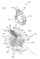
- Fig. 1 relates to a change-over holder system 100 with a base part 110 and a change-over holder 120.
- a chisel 130 which is designed as a so-called round shank chisel exists.
- a plurality of such swap-holder systems 100 are applied to a cylindrical roller for use and brought into rotation in working direction AR during use.
- the FIGS. 1 to 4 and 11 illustrate the structure and operation of the interchangeable holder system 100 and will be explained together in more detail below.
- the chisel 130 comprises a cylindrical bearing shaft 131 and a chisel head 132 with a contact surface 133 facing the changeover holder 120 and a chisel tip 134 facing away from the changeover holder 120.
- the chisel 130 is arranged in the changer holder 120 and is held by the latter.
- the change holder 120 has a cylindrical bit receptacle 121 which extends linearly along the longitudinal axis A1 of the exchangeable holder 120 from the bit insert or the annular bit stop surface 122.
- the longitudinal axis A1 of the interchangeable holder 120 is thus defined defined by the longitudinal axis of the bit holder 121 or by the coaxially extending axis of rotation A1 of the recorded in the bit holder 121 round shank chisel 130.
- the bit 130 is braced with a clamping sleeve 135 with the inner wall of the bit receptacle 121.
- the bit receptacle 121 leads to the rear into an outlet opening 122, which is open to the outside of the exchangeable holder system 100 and establishes a connection from the rear of the bit 130 mounted in the bit receptacle 121 to the outside environment of the exchangeable holder system 100. Through the exit bore, access to the front end of the bit 130 received in the bit receptacle 121 is possible, for example, for disassembly purposes.
- the bit receptacle 121 is part of a bearing body 123 of the exchangeable holder 120 which, in the axial direction of the longitudinal axis A1 of the bit receptacle 121, initially has a cone-shaped rear region mounted in the base part 110 and a projecting front region.
- the bearing body 123 is thus formed longitudinally along the axis A1.
- the cylinder axis of the bit 130 and the longitudinal axis A1 of the bit receptacle 121 are coaxial.
- the changeover holder 120 comprises a Basisumgriff 126, with respect to the axis A1 in Radially protrudes outward and has a web portion 127 and a Umgriffarm 128.
- the base gripping 126 thus protrudes outward in the radial direction with respect to the longitudinal axis A1 of the bearing part 123 and has in its end region a cranked over or protruding gripping arm 128 bent over in the insertion direction.
- a receiving space is formed between the wraparound arm 128 and the outer wall of the bearing part 123 opposite thereto, into which a support projection 111 of the base part 110 is received when inserting the exchangeable holder 120 into the base part 110.
- This area is thus generally U-shaped on average, wherein the Umgriffarm 128 forms a leg of this U-profile and has on its inner side a bearing surface 180.
- the base part 110 further has an assembly area 113 located on the underside with fastening feet, via which the base part 110 is welded onto, for example, a cylindrical body of a milling drum.
- the Basisumgriff 126 is relative to the axes A1, A2, or A3 in the radial direction in the direction of the mounting portion 113 and the Umgriffarm 128 is bent in the direction of insertion.
- a change holder receptacle 114 is also provided, which is designed to receive the rear region 124 of the bearing body 123.
- the change-holder receptacle 124 is also substantially (hollow) conical or complementary to the conical region of the replaceable holder 120 and forms in this region a receptacle into which the bearing body 123 partially or completely comes into abutment in the inserted state.
- an outlet opening 115 is also present, coming from the outside into the outlet hole 122 in the removable holder 120, so that the back of the inserted into the bit holder 121 bit 130 from the outside through the outlet opening 115th and the exit port 122 is accessible.
- the changeover holder 120 in the insertion direction B As shown in Fig. 2 shown is inserted.
- the Basisumgriff 126 is thereby pushed onto the base part 110 and engages around the support projection 111 in the radial direction to the longitudinal axis A1 of the Kirhalterfact 114.
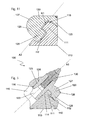
- Envelope here means thus that the Basisumgriff 126 and the corresponding region of the bearing body 123 on both sides of the support projection 111 [at the two in the radial direction opposite sides 111a (radially outer side of the support projection 111) and 111b (radially inner side of the support projection)] and sandwich the support projection 111 in this area.
- the radially outer side of the support projection 111a extends in the axial direction further obliquely to the longitudinal axis A1 of the bit holder in the changeover holder.
- This side is designed as a plane contact surface for the base grip 128 or for the contact surface 180.
- In the longitudinal section plane in Fig. 4 are the longitudinal axis A1 and the longitudinal axis A2 of the wall 111a and parallel thereto extending inner edge 124a of the rear portion of the bearing body 123 with the axis A3 (corresponding to the insertion axis) at the angle ⁇ to each other.
- This special design has the advantage that the support projection 126 is not formed at right angles but undercut relative to the outer side wall 111a in the direction of insertion C and thus represents a hook-like security in the longitudinal direction A1 of the bit holder.
- the changeover holder 120 is inserted into abutment against the mounting edge A3 in the direction B in the base part 110.
- the changeover holder 120 is also fixed against rotation on the base part 110.
- the rotation is also ensured by the retracted in the state with its Basisumgriff 126 the support projection 111 encompassing Umgriffarm 128 in the inserted state relative to the cone axis A1 or longitudinal axis of the change holder 120 in the radial direction, comparable to one, based on the circular in the radial plane Chisel holder 121, Passante, which is in a positive connection with the base handle 126.
- the rotational movement is blocked in this plane and the changeover holder 120 mounted against rotation about the axis A1 against the base part 110.
- the extent of the insertion movement is limited by abutment of the cone outer surface of the rear region 124 of the bearing body 123 on the cone inner wall of the base part 110 in the removable holder receptacle 114. This space is also sealed to the outside by a seal, specifically the O-ring seal 116.
- the change holder 120 comes in the direction of insertion neither with its base handle 126 nor with the front end of the bearing body 123 for direct contact with the base part 110, so that in the direction of insertion B quite still settlements can occur in the working mode. For this reason, the free spaces H1 and H2 are present in the insertion direction in these areas between the base part 110 and the changeover holder 120.
- a screw 150 is present, which is screwed through a suitable bore in the base part 110 in an internally threaded portion 151 in the removable holder 120 from the rear.
- the longitudinal axis of the screw lies coaxially with the longitudinal axis A1.
- the screw connection with the screw 150 is further cushioned by a spring washer 152, so that possibly occurring in the insertion direction B or in the axial direction C settlements are compensated during operation.
- sloping wedge surfaces which effect a better guidance of the milled material, are disposed in each case symmetrically with respect to the mounting region 113.
- This arrangement is also referred to collectively as Materialleit Scheme comprising a changeover-side part 129 and a base part-side part 119.
- An essential advantage of the interchangeable holder system 110 is first that the mounting of the interchangeable holder 120 on the base part 110 is particularly simple, since the interchangeable holder 120 can be pushed accurately on the base part 110.
- a guarantee of the correct positioning is achieved in particular by the relative to the base 110 rotatably mounted changeover holder 120 by means of the support projection 111 encompassing base handle 126, which thus corresponds to a total positive guidance of the change holder 120 in the base part 110.
- a further advantage lies in the fact that a force relief of the forces acting on the changeover holder forces is caused by the wrap. Usually act in the working mode applied to the bit 130 counterforce by the substrate to be processed in the direction of arrow F on the chisel 130. This force is transmitted to the changeover holder 120.
- Fig. 5 shows the longitudinal section of an alternative embodiment of the exchange system 100 from the FIGS. 1 to 4 , Wherein structurally identical or functionally identical components are provided with the same reference numerals.
- the main difference of the exchange system 100 from Fig. 5 consists in the manner of performing the fixation of the change holder 120 on the base part 110, which in contrast to the embodiment according to the FIGS. 1 to 4 in Fig. 5 is achieved by a cylindrical seat, specifically a press fit.
- An additional backup of the change holder 120 in the base part 110 for example by a fixing screw, is therefore not required.
- In the longitudinal direction two further with respect to the axis A1 in the axial direction one behind the other O-ring seals are also available.
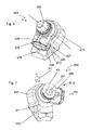
- FIGS. 6, 7 . 8 and 9 show different views of a further embodiment of a change-holder system 200, which corresponds in its basic structure to the aforementioned change-holder system.
- a change-holder system 200 which corresponds in its basic structure to the aforementioned change-holder system.
- the essential difference between the interchangeable-holder system 200 and the interchangeable-holder system 100 is the design of the base part 210 and the interchangeable holder 220 in such a way that the interchangeable holder 220 can be introduced into the base part 210 in a combined insertion and rotation movement.
- the embracing of the support projection 211 by the Basisumgriff 226 succeeds in this embodiment, not only by inserting the change holder into the base part or pushing the Basisumgriffs on the support projection, but by a combined insertion and Einfusement.
- Basisumgriff 226 is undercut and thus in the installed state against the insertion direction B forms a hook member which secures the change holder 220 with respect to its axial displacement against the insertion direction B relative to the base part 210.
- This is particularly clear from a comparison of the position of the longitudinal axis A1 and the parallel cylindrical wall in the change holder receptacle 214 A2 or the thus in contact cylindrical region of the change holder 220 with the axis A3 extending obliquely thereto.
- the axis A3 extends along the contact surface between the facing to the changeover holder 220 portion of the Umgriffarms 228 of the base handle 226 and the radially outwardly facing portion of the support projection 211.
- the existing there on the changeover holder 220 contact surface 280 corresponds to a curved axis about the longitudinal axis A1, the in their training corresponds to a surface section of a cone.
- these axes converge at an angle ⁇ and intersect. It is thus not possible to withdraw the changeover holder 220 in its installed and screwed state from the base part 210 against the insertion direction B. Rather, this is prevented by the gripping arm 228 of the base gripping 226 engaging behind the supporting projection 211.
- the change holder 220 or the base handle thus forms a kind of bayonet closure with the base part 110 or its support projection.
- the changeover holder 220 relative to the base part 210, at least in the area between the state behind the support projection 211 and the adoptedgerehten insertion state pivotally relative to the base part 210.
- pivot limitations for example in the groove 212 or the support projection 211 is possible, that is in the FIGS. 6 to 9 illustrated embodiment formed in such a way that the changeover holder 220 in the inserted into the base member 210 state by 360 ° about the rotation axis D (which is coaxial with the axis A1, is rotatable.
- an anti-twist device is also provided in the exchangeable holder system 200. Specifically, this is obtained by a securing screw 250, which screws the change holder 220 to the base part 210 perpendicular to the longitudinal axis or axis of rotation.
- the screw 250 is therefore almost completely decoupled with respect to the change holder acting, transmitted by the bit forces (except possibly occurring torsional forces of the round shank bit 230) and therefore has a very long life.
- To disassemble the screw 250 must first be removed and removed (arrow P1) and then the changeover holder 220 from the position in Fig. 6 rotated in the direction of arrow P2 from the engagement of the Basisumgriffs 126 on the support projection 111 out and then pulled against the insertion direction B from the base part 210 out (for mounting in accordance with the opposite order). This will be explained in more detail below.
- the base part 210 and the interchangeable holder 220 are rearward, i. pointing away from the tip of the bit 230 pointing generously open in both the axial and perpendicular to the axial direction outward and thus allows, for example, access to the back of the bit in the bit receptacle 221.
- This opening also facilitates cleaning and cooling of the entire system, as the Chisel 230 and the change holder 220 are directly accessible from behind.
- the bit receptacle 221 is also rectilinear and the changeover holder formed completely continuous.
- the Kirhalterability 214 is also straight and the base member 210 formed completely continuous and arranged with respect to its longitudinal axis coaxial with the bit 230 and coaxial with the longitudinal axis of the bit holder 221.
- FIG. 7 illustrates the essential characteristic of the embodiment of the interchangeable holder system 200 with the manner of a bayonet closure connection manner between the base part 210 and the changeover holder 220.
- FIG. 7 indicates thereby starting from the state in FIG. 6 the dismantling steps again. Accordingly, the mounting purposes for installing the exchangeable holder 220 into the base part 210 are in reverse order. First, the fastening screw 250 is released, whereby the achieved with the screw 250 against rotation of the removable holder 220 relative to the base part 210 is repealed. Therefore, the changeover holder 220 can be rotated in a next step about the rotation axis D in the direction of arrow P2 from the bayonet mount.
- the base handle 226 must be rotated so far that it comes out of engagement with the formed in the support projection 211 undercut. Then the Change holder 220 in the direction of arrow P3 or opposite to the insertion direction of the change holder 220 in the base part 210 are pulled out of the base part 210.
- this embodiment also enables the force relief already mentioned above for working example 100 in working mode. In this case, the force F is introduced in the direction of arrow F in the round shank chisel 230 and the entire changeover holder 220 thus pushed in the direction of arrow F, which can lead to significant material loads.
- Basisumgriff 226 relief takes place in such a manner that the contact surface 280 abuts against the inner surface of the U-leg of the Basisumgriffs 226 on the counter surface 211 a and in this area allows a force transmission of the loading force F.
- Fig. 12 clarifies the investment conditions of the embodiment of the FIGS. 6 to 9 with respect to the base gripping 226 on the support projection 211.
- the base gripping 226 also abuts with its web region 227 in the direction of insertion against the abutment surface 260 of the support projection 211.
- the parallel surface in the end region of the wraparound arm 228 in the insertion direction is spaced from the bottom of the groove 212 (free space FR).
- FIG. 10 a longitudinal sectional view of a further variant of the interchangeable-holder system 200 is concerned, in which case the positioning of the anti-rotation device has been varied.
- a top-mounted clamping pin 270 is also inserted transversely to the axis of rotation in a superimposed bore 261 in the base part 210 and the removable holder 220 and thus prevents the rotational capability of the removable holder 220 relative to the base part 210.
Landscapes
- Engineering & Computer Science (AREA)
- Mining & Mineral Resources (AREA)
- Mechanical Engineering (AREA)
- Drilling And Exploitation, And Mining Machines And Methods (AREA)
- Jigs For Machine Tools (AREA)
- Cutting Tools, Boring Holders, And Turrets (AREA)
Priority Applications (1)
| Application Number | Priority Date | Filing Date | Title |
|---|---|---|---|
| PL11007139T PL2425951T3 (pl) | 2010-09-07 | 2011-09-02 | System imaka wymiennego dla dłuta |
Applications Claiming Priority (1)
| Application Number | Priority Date | Filing Date | Title |
|---|---|---|---|
| DE102010044649A DE102010044649A1 (de) | 2010-09-07 | 2010-09-07 | Wechselhaltersystem für einen Meißel |
Publications (2)
| Publication Number | Publication Date |
|---|---|
| EP2425951A1 true EP2425951A1 (fr) | 2012-03-07 |
| EP2425951B1 EP2425951B1 (fr) | 2015-06-10 |
Family
ID=44587612
Family Applications (1)
| Application Number | Title | Priority Date | Filing Date |
|---|---|---|---|
| EP11007139.6A Active EP2425951B1 (fr) | 2010-09-07 | 2011-09-02 | Système de support de remplacement pour un couteau |
Country Status (6)
| Country | Link |
|---|---|
| US (1) | US9004610B2 (fr) |
| EP (1) | EP2425951B1 (fr) |
| CN (1) | CN102535320B (fr) |
| DE (1) | DE102010044649A1 (fr) |
| DK (1) | DK2425951T3 (fr) |
| PL (1) | PL2425951T3 (fr) |
Cited By (2)
| Publication number | Priority date | Publication date | Assignee | Title |
|---|---|---|---|---|
| CN109944144A (zh) * | 2019-04-08 | 2019-06-28 | 苏州五元素机械制造有限公司 | 一种快换工具保持架系统 |
| DE102021112757A1 (de) | 2021-05-17 | 2022-11-17 | Bomag Gmbh | WECHSELHALTER, MEIßELWECHSELHALTERSYSTEM, FRÄSWALZE FÜR EINE STRAßENFRÄSMASCHINE UND STRAßENFRÄSMASCHINE |
Families Citing this family (58)
| Publication number | Priority date | Publication date | Assignee | Title |
|---|---|---|---|---|
| US11261731B1 (en) | 2014-04-23 | 2022-03-01 | The Sollami Company | Bit holder and unitary bit/holder for use in shortened depth base blocks |
| US10598013B2 (en) | 2010-08-27 | 2020-03-24 | The Sollami Company | Bit holder with shortened nose portion |
| US10072501B2 (en) | 2010-08-27 | 2018-09-11 | The Sollami Company | Bit holder |
| US9879531B2 (en) | 2014-02-26 | 2018-01-30 | The Sollami Company | Bit holder shank and differential interference between the shank distal portion and the bit holder block bore |
| US10385689B1 (en) | 2010-08-27 | 2019-08-20 | The Sollami Company | Bit holder |
| US10370966B1 (en) * | 2014-04-23 | 2019-08-06 | The Sollami Company | Rear of base block |
| US10337324B2 (en) | 2015-01-07 | 2019-07-02 | The Sollami Company | Various bit holders and unitary bit/holders for use with shortened depth bit holder blocks |
| AU2011253666B8 (en) | 2010-11-30 | 2014-09-25 | Joy Global Surface Mining Inc | Pick Assembly |
| USD720375S1 (en) * | 2011-11-30 | 2014-12-30 | Harnischfeger Technologies, Inc. | Pick holder |
| USD709112S1 (en) * | 2011-11-30 | 2014-07-15 | Harnischfeger Technologies, Inc. | Pick holder |
| US20130169023A1 (en) * | 2011-12-28 | 2013-07-04 | Sandvik Intellectual Property Ab | Bit Sleeve with Compression Band Retainers |
| USD693390S1 (en) * | 2012-04-16 | 2013-11-12 | Bomag Gmbh | Cone quick-change tool holder |
| US10260342B1 (en) | 2012-10-19 | 2019-04-16 | The Sollami Company | Combination polycrystalline diamond bit and bit holder |
| US10180065B1 (en) | 2015-10-05 | 2019-01-15 | The Sollami Company | Material removing tool for road milling mining and trenching operations |
| US9909416B1 (en) | 2013-09-18 | 2018-03-06 | The Sollami Company | Diamond tipped unitary holder/bit |
| US10107097B1 (en) | 2012-10-19 | 2018-10-23 | The Sollami Company | Combination polycrystalline diamond bit and bit holder |
| US9988903B2 (en) | 2012-10-19 | 2018-06-05 | The Sollami Company | Combination polycrystalline diamond bit and bit holder |
| US10323515B1 (en) | 2012-10-19 | 2019-06-18 | The Sollami Company | Tool with steel sleeve member |
| US10105870B1 (en) | 2012-10-19 | 2018-10-23 | The Sollami Company | Combination polycrystalline diamond bit and bit holder |
| DE102014001921B4 (de) | 2013-02-22 | 2024-08-22 | Bomag Gmbh | Fräswalze mit einer, insbesondere austauschbaren, Materialleiteinrichtung |
| DE102013005594A1 (de) | 2013-04-03 | 2014-10-09 | Bomag Gmbh | Bodenfräsmaschine und Verfahren zum Austauschen der Fräswalze einer Bodenfräsmaschine |
| US10794181B2 (en) | 2014-04-02 | 2020-10-06 | The Sollami Company | Bit/holder with enlarged ballistic tip insert |
| US10633971B2 (en) | 2016-03-07 | 2020-04-28 | The Sollami Company | Bit holder with enlarged tire portion and narrowed bit holder block |
| US10995613B1 (en) | 2013-09-18 | 2021-05-04 | The Sollami Company | Diamond tipped unitary holder/bit |
| US10876402B2 (en) | 2014-04-02 | 2020-12-29 | The Sollami Company | Bit tip insert |
| US10947844B1 (en) * | 2013-09-18 | 2021-03-16 | The Sollami Company | Diamond Tipped Unitary Holder/Bit |
| US9976418B2 (en) | 2014-04-02 | 2018-05-22 | The Sollami Company | Bit/holder with enlarged ballistic tip insert |
| US10415386B1 (en) | 2013-09-18 | 2019-09-17 | The Sollami Company | Insertion-removal tool for holder/bit |
| US10767478B2 (en) | 2013-09-18 | 2020-09-08 | The Sollami Company | Diamond tipped unitary holder/bit |
| US10577931B2 (en) | 2016-03-05 | 2020-03-03 | The Sollami Company | Bit holder (pick) with shortened shank and angular differential between the shank and base block bore |
| US10968739B1 (en) | 2013-09-18 | 2021-04-06 | The Sollami Company | Diamond tipped unitary holder/bit |
| US11168563B1 (en) | 2013-10-16 | 2021-11-09 | The Sollami Company | Bit holder with differential interference |
| US9212553B2 (en) * | 2013-11-08 | 2015-12-15 | The Sollami Company | Dirt and rock cutting bit tool |
| US11339656B1 (en) * | 2014-02-26 | 2022-05-24 | The Sollami Company | Rear of base block |
| DE102015002712A1 (de) | 2014-03-10 | 2015-09-10 | Bomag Gmbh | Rundschaftmeißelanordnung, Sicherungsring für eine Rundschaftmeißelanordnung, Set mit einer Spannhülse und einem Sicherungsring und Verfahren zum Sichern eines Rundschaftmeißels in einem Meißelhalter |
| US11339654B2 (en) | 2014-04-02 | 2022-05-24 | The Sollami Company | Insert with heat transfer bore |
| US11891895B1 (en) * | 2014-04-23 | 2024-02-06 | The Sollami Company | Bit holder with annular rings |
| DE102014015584B4 (de) | 2014-10-21 | 2018-10-25 | Bomag Gmbh | Fräswalze und Bodenfräsmaschine mit derartiger Fräswalze |
| CN104452559B (zh) * | 2014-10-23 | 2017-01-11 | 湖南三一路面机械有限公司 | 一种铣刨机及其铣刨鼓、快换刀座系统 |
| DE102014016500A1 (de) | 2014-11-07 | 2016-05-12 | Bomag Gmbh | Werkzeugeinrichtung für eine Bodenfräsmaschine und Bodenfräsmaschine mit einer solchen Werkzeugeinrichtung |
| US10502056B2 (en) | 2015-09-30 | 2019-12-10 | The Sollami Company | Reverse taper shanks and complementary base block bores for bit assemblies |
| US10167720B2 (en) | 2016-01-13 | 2019-01-01 | Caterpillar Paving Products Inc. | Milling tool holder |
| US10113424B2 (en) | 2016-01-13 | 2018-10-30 | Caterpillar Paving Products Inc. | Milling tool holder |
| US10184336B2 (en) | 2016-01-13 | 2019-01-22 | Caterpillar Paving Products Inc. | Milling tool holder |
| CN105714664B (zh) * | 2016-03-15 | 2018-12-11 | 湖南三一路面机械有限公司 | 快换刀座组件、铣刨鼓及铣刨机 |
| US10612376B1 (en) | 2016-03-15 | 2020-04-07 | The Sollami Company | Bore wear compensating retainer and washer |
| US10246999B2 (en) | 2016-03-23 | 2019-04-02 | Caterpillar Paving Products Inc. | Locking system to prevent rotation of toolholder |
| US10876401B1 (en) | 2016-07-26 | 2020-12-29 | The Sollami Company | Rotational style tool bit assembly |
| DE102017002084A1 (de) | 2017-03-03 | 2018-09-06 | Bomag Gmbh | Werkzeugwechselhaltersystem mit einem Grundhalter und einem Wechselhalter sowie Verfahren zum Herstellen eines Werkzeugwechselhaltersystems |
| US10968738B1 (en) | 2017-03-24 | 2021-04-06 | The Sollami Company | Remanufactured conical bit |
| US11187080B2 (en) | 2018-04-24 | 2021-11-30 | The Sollami Company | Conical bit with diamond insert |
| US11279012B1 (en) | 2017-09-15 | 2022-03-22 | The Sollami Company | Retainer insertion and extraction tool |
| DE102017011131A1 (de) | 2017-12-01 | 2019-06-06 | Bomag Gmbh | Hochverschleißfester, einstückiger Meißelspitzenkörper, Fräsmeißel für eine Bodenfräsmaschine, Fräswalze sowie Bodenfräsmaschine |
| USD896289S1 (en) * | 2018-07-10 | 2020-09-15 | Bomag Gmbh | Quick-change toolholder |
| US11103939B2 (en) * | 2018-07-18 | 2021-08-31 | The Sollami Company | Rotatable bit cartridge |
| US12345158B1 (en) | 2019-06-20 | 2025-07-01 | The Sollami Company | Bit tip insert |
| US11208887B2 (en) * | 2019-08-23 | 2021-12-28 | Caterpillar Paving Products Inc. | Tool holder installation device and system |
| US12473829B1 (en) * | 2021-01-12 | 2025-11-18 | The Sollami Company | Bit holder with slotted shank and annular ring |
Citations (7)
| Publication number | Priority date | Publication date | Assignee | Title |
|---|---|---|---|---|
| DE3117639A1 (de) * | 1980-06-17 | 1982-08-12 | Anderson Strathclyde Ltd., High Wycombe, Buckinghamshire | "abnehmbarer pickenhalter" |
| DE8805961U1 (de) * | 1988-04-16 | 1988-06-23 | Fa. Michael Komotzki, 4600 Dortmund | Halterung für Meißel für Maschinen zum Abtragen von Gesteinen und Mineralien |
| DE3909425C1 (en) * | 1989-03-22 | 1990-08-23 | Fa. Michael Komotzki, 4600 Dortmund, De | Holder for picks for machines for excavating mineral substances |
| DE29510913U1 (de) * | 1995-07-06 | 1995-09-28 | Wagener, Helmut, 53577 Neustadt | Vorrichtung zur Halterung eines Fräsmeißels |
| DE102004030691A1 (de) * | 2004-06-24 | 2006-01-19 | Wirtgen Gmbh | Werkzeug-Haltevorrichtung |
| DE102005017760A1 (de) * | 2005-04-18 | 2006-10-19 | Michael Steinbrecher | Schnellwechselhaltersystem |
| DE102009052351A1 (de) * | 2009-11-07 | 2011-05-12 | Michael Steinbrecher | Fräswalze |
Family Cites Families (7)
| Publication number | Priority date | Publication date | Assignee | Title |
|---|---|---|---|---|
| US2242808A (en) * | 1940-01-23 | 1941-05-20 | Laplant Choate Mfg Co Inc | Earth tamper |
| US4335921A (en) * | 1977-06-06 | 1982-06-22 | Cmi Corporation | Cutting head for a paved roadway resurfacing apparatus |
| US4343516A (en) * | 1980-08-11 | 1982-08-10 | Ingersoll-Rand Company | Cutter bit assembly |
| US5040850A (en) * | 1990-09-11 | 1991-08-20 | Michael Komotzki | Tool supporting structure for use in material removing machines |
| DE19922206C2 (de) * | 1999-05-14 | 2002-02-28 | Betek Bergbau & Hartmetall | Werkzeug für eine Schräm-, Bergbau- oder Straßenfräsmaschine |
| US6729052B2 (en) * | 2001-11-09 | 2004-05-04 | Esco Corporation | Assembly for securing an excavating tooth |
| DE102008045825B3 (de) * | 2008-09-05 | 2010-05-27 | Wirtgen Gmbh | Meißelhalter für eine Schrämmaschine, Straßenfräse, Suface-Miner oder dergleichen |
-
2010
- 2010-09-07 DE DE102010044649A patent/DE102010044649A1/de not_active Withdrawn
-
2011
- 2011-09-02 DK DK11007139.6T patent/DK2425951T3/en active
- 2011-09-02 EP EP11007139.6A patent/EP2425951B1/fr active Active
- 2011-09-02 PL PL11007139T patent/PL2425951T3/pl unknown
- 2011-09-07 CN CN201110362030.3A patent/CN102535320B/zh active Active
- 2011-09-07 US US13/226,682 patent/US9004610B2/en active Active
Patent Citations (7)
| Publication number | Priority date | Publication date | Assignee | Title |
|---|---|---|---|---|
| DE3117639A1 (de) * | 1980-06-17 | 1982-08-12 | Anderson Strathclyde Ltd., High Wycombe, Buckinghamshire | "abnehmbarer pickenhalter" |
| DE8805961U1 (de) * | 1988-04-16 | 1988-06-23 | Fa. Michael Komotzki, 4600 Dortmund | Halterung für Meißel für Maschinen zum Abtragen von Gesteinen und Mineralien |
| DE3909425C1 (en) * | 1989-03-22 | 1990-08-23 | Fa. Michael Komotzki, 4600 Dortmund, De | Holder for picks for machines for excavating mineral substances |
| DE29510913U1 (de) * | 1995-07-06 | 1995-09-28 | Wagener, Helmut, 53577 Neustadt | Vorrichtung zur Halterung eines Fräsmeißels |
| DE102004030691A1 (de) * | 2004-06-24 | 2006-01-19 | Wirtgen Gmbh | Werkzeug-Haltevorrichtung |
| DE102005017760A1 (de) * | 2005-04-18 | 2006-10-19 | Michael Steinbrecher | Schnellwechselhaltersystem |
| DE102009052351A1 (de) * | 2009-11-07 | 2011-05-12 | Michael Steinbrecher | Fräswalze |
Cited By (3)
| Publication number | Priority date | Publication date | Assignee | Title |
|---|---|---|---|---|
| CN109944144A (zh) * | 2019-04-08 | 2019-06-28 | 苏州五元素机械制造有限公司 | 一种快换工具保持架系统 |
| DE102021112757A1 (de) | 2021-05-17 | 2022-11-17 | Bomag Gmbh | WECHSELHALTER, MEIßELWECHSELHALTERSYSTEM, FRÄSWALZE FÜR EINE STRAßENFRÄSMASCHINE UND STRAßENFRÄSMASCHINE |
| EP4092192A1 (fr) | 2021-05-17 | 2022-11-23 | BOMAG GmbH | Support de changement pour système de support de changement d'outil pour la fixation d'une fraise sur un tambour de fraisage d'une fraiseuse routière |
Also Published As
| Publication number | Publication date |
|---|---|
| DK2425951T3 (en) | 2015-09-07 |
| CN102535320A (zh) | 2012-07-04 |
| US9004610B2 (en) | 2015-04-14 |
| DE102010044649A1 (de) | 2012-03-08 |
| US20120068527A1 (en) | 2012-03-22 |
| PL2425951T3 (pl) | 2015-12-31 |
| CN102535320B (zh) | 2016-01-06 |
| EP2425951B1 (fr) | 2015-06-10 |
Similar Documents
| Publication | Publication Date | Title |
|---|---|---|
| EP2425951B1 (fr) | Système de support de remplacement pour un couteau | |
| DE112011103744B4 (de) | Wechselhaltersystem für einen Meißel | |
| EP2336488B1 (fr) | Porte-pic et élément de base | |
| EP2336489B1 (fr) | Porte-pic et élément de base pour la réception d'un porte-pic | |
| EP2729666B1 (fr) | Porte-outil pour une machine de travail du sol | |
| DE10221764C1 (de) | Halterung für einen Schaftmeißel | |
| EP3049621A2 (fr) | Support de trépan et combinaison d'un support de trépan avec un trépan | |
| EP2379260B1 (fr) | Outil pour usinage par enlèvement de copeaux, en particulier outil pour tournage longitudinal | |
| DE102011051520B4 (de) | Meißelhalter | |
| CH714193A2 (de) | Bohrkrone. | |
| WO2020259866A1 (fr) | Pic de fraisage pour une machine à fraiser le sol, système porte-pic, tambour de fraisage | |
| DE102011051584A1 (de) | Verfahren zur Lagerung eines Meißels sowie zugehörige Vorrichtung | |
| EP3854988A1 (fr) | Adaptateur pour un accouplement sans outil de couronne de forage | |
| DE102005055544A1 (de) | Halterungseinrichtung zum Haltern von Meißeln | |
| EP3292931B1 (fr) | Outil, notamment pour l'usinage de pièces à enlèvement de copeaux | |
| WO2004092542A1 (fr) | Corps de coupe cylindrique | |
| DE3242144C2 (de) | Dreh-Kippmeißel | |
| DE2538682C2 (de) | Meißel für Kohlenhobel | |
| EP2754854B1 (fr) | Procédé de fixation d'un pic ainsi que dispositif correspondant | |
| DE20215460U1 (de) | Montage-/Demontagewerkzeug für Fräser | |
| DE102024112602A1 (de) | Meißelhalter | |
| DE102005034425A1 (de) | Werkzeug | |
| DE3526994C1 (de) | Vorrichtung zur Aufnahme eines Meißels für Schräm- und Bohrmaschinen und dgl., insbesondere für Vortriebs- und Gewinnungsmaschinen | |
| DE20007156U1 (de) | Schlüsselwerkzeug | |
| DE202009014879U1 (de) | Meißelhalter und Basisteil |
Legal Events
| Date | Code | Title | Description |
|---|---|---|---|
| AK | Designated contracting states |
Kind code of ref document: A1 Designated state(s): AL AT BE BG CH CY CZ DE DK EE ES FI FR GB GR HR HU IE IS IT LI LT LU LV MC MK MT NL NO PL PT RO RS SE SI SK SM TR |
|
| AX | Request for extension of the european patent |
Extension state: BA ME |
|
| PUAI | Public reference made under article 153(3) epc to a published international application that has entered the european phase |
Free format text: ORIGINAL CODE: 0009012 |
|
| 17P | Request for examination filed |
Effective date: 20120907 |
|
| RIC1 | Information provided on ipc code assigned before grant |
Ipc: B28D 1/18 20060101AFI20141031BHEP |
|
| GRAP | Despatch of communication of intention to grant a patent |
Free format text: ORIGINAL CODE: EPIDOSNIGR1 |
|
| INTG | Intention to grant announced |
Effective date: 20150224 |
|
| GRAS | Grant fee paid |
Free format text: ORIGINAL CODE: EPIDOSNIGR3 |
|
| GRAA | (expected) grant |
Free format text: ORIGINAL CODE: 0009210 |
|
| AK | Designated contracting states |
Kind code of ref document: B1 Designated state(s): AL AT BE BG CH CY CZ DE DK EE ES FI FR GB GR HR HU IE IS IT LI LT LU LV MC MK MT NL NO PL PT RO RS SE SI SK SM TR |
|
| REG | Reference to a national code |
Ref country code: GB Ref legal event code: FG4D Free format text: NOT ENGLISH |
|
| REG | Reference to a national code |
Ref country code: CH Ref legal event code: EP |
|
| REG | Reference to a national code |
Ref country code: AT Ref legal event code: REF Ref document number: 730703 Country of ref document: AT Kind code of ref document: T Effective date: 20150715 |
|
| REG | Reference to a national code |
Ref country code: DE Ref legal event code: R096 Ref document number: 502011007023 Country of ref document: DE |
|
| REG | Reference to a national code |
Ref country code: IE Ref legal event code: FG4D Free format text: LANGUAGE OF EP DOCUMENT: GERMAN |
|
| REG | Reference to a national code |
Ref country code: DK Ref legal event code: T3 Effective date: 20150903 |
|
| REG | Reference to a national code |
Ref country code: SE Ref legal event code: TRGR |
|
| REG | Reference to a national code |
Ref country code: FR Ref legal event code: PLFP Year of fee payment: 5 |
|
| REG | Reference to a national code |
Ref country code: CH Ref legal event code: NV Representative=s name: HEPP WENGER RYFFEL AG, CH |
|
| PG25 | Lapsed in a contracting state [announced via postgrant information from national office to epo] |
Ref country code: FI Free format text: LAPSE BECAUSE OF FAILURE TO SUBMIT A TRANSLATION OF THE DESCRIPTION OR TO PAY THE FEE WITHIN THE PRESCRIBED TIME-LIMIT Effective date: 20150610 Ref country code: ES Free format text: LAPSE BECAUSE OF FAILURE TO SUBMIT A TRANSLATION OF THE DESCRIPTION OR TO PAY THE FEE WITHIN THE PRESCRIBED TIME-LIMIT Effective date: 20150610 Ref country code: LT Free format text: LAPSE BECAUSE OF FAILURE TO SUBMIT A TRANSLATION OF THE DESCRIPTION OR TO PAY THE FEE WITHIN THE PRESCRIBED TIME-LIMIT Effective date: 20150610 |
|
| REG | Reference to a national code |
Ref country code: NO Ref legal event code: T2 Effective date: 20150610 |
|
| PG25 | Lapsed in a contracting state [announced via postgrant information from national office to epo] |
Ref country code: RS Free format text: LAPSE BECAUSE OF FAILURE TO SUBMIT A TRANSLATION OF THE DESCRIPTION OR TO PAY THE FEE WITHIN THE PRESCRIBED TIME-LIMIT Effective date: 20150610 Ref country code: BG Free format text: LAPSE BECAUSE OF FAILURE TO SUBMIT A TRANSLATION OF THE DESCRIPTION OR TO PAY THE FEE WITHIN THE PRESCRIBED TIME-LIMIT Effective date: 20150910 Ref country code: GR Free format text: LAPSE BECAUSE OF FAILURE TO SUBMIT A TRANSLATION OF THE DESCRIPTION OR TO PAY THE FEE WITHIN THE PRESCRIBED TIME-LIMIT Effective date: 20150911 Ref country code: LV Free format text: LAPSE BECAUSE OF FAILURE TO SUBMIT A TRANSLATION OF THE DESCRIPTION OR TO PAY THE FEE WITHIN THE PRESCRIBED TIME-LIMIT Effective date: 20150610 |
|
| REG | Reference to a national code |
Ref country code: NL Ref legal event code: MP Effective date: 20150610 |
|
| REG | Reference to a national code |
Ref country code: PL Ref legal event code: T3 |
|
| PG25 | Lapsed in a contracting state [announced via postgrant information from national office to epo] |
Ref country code: EE Free format text: LAPSE BECAUSE OF FAILURE TO SUBMIT A TRANSLATION OF THE DESCRIPTION OR TO PAY THE FEE WITHIN THE PRESCRIBED TIME-LIMIT Effective date: 20150610 |
|
| PG25 | Lapsed in a contracting state [announced via postgrant information from national office to epo] |
Ref country code: SK Free format text: LAPSE BECAUSE OF FAILURE TO SUBMIT A TRANSLATION OF THE DESCRIPTION OR TO PAY THE FEE WITHIN THE PRESCRIBED TIME-LIMIT Effective date: 20150610 Ref country code: PT Free format text: LAPSE BECAUSE OF FAILURE TO SUBMIT A TRANSLATION OF THE DESCRIPTION OR TO PAY THE FEE WITHIN THE PRESCRIBED TIME-LIMIT Effective date: 20151012 Ref country code: IS Free format text: LAPSE BECAUSE OF FAILURE TO SUBMIT A TRANSLATION OF THE DESCRIPTION OR TO PAY THE FEE WITHIN THE PRESCRIBED TIME-LIMIT Effective date: 20151010 Ref country code: CZ Free format text: LAPSE BECAUSE OF FAILURE TO SUBMIT A TRANSLATION OF THE DESCRIPTION OR TO PAY THE FEE WITHIN THE PRESCRIBED TIME-LIMIT Effective date: 20150610 Ref country code: RO Free format text: LAPSE BECAUSE OF NON-PAYMENT OF DUE FEES Effective date: 20150610 |
|
| REG | Reference to a national code |
Ref country code: DE Ref legal event code: R097 Ref document number: 502011007023 Country of ref document: DE |
|
| PLBE | No opposition filed within time limit |
Free format text: ORIGINAL CODE: 0009261 |
|
| STAA | Information on the status of an ep patent application or granted ep patent |
Free format text: STATUS: NO OPPOSITION FILED WITHIN TIME LIMIT |
|
| PG25 | Lapsed in a contracting state [announced via postgrant information from national office to epo] |
Ref country code: MC Free format text: LAPSE BECAUSE OF FAILURE TO SUBMIT A TRANSLATION OF THE DESCRIPTION OR TO PAY THE FEE WITHIN THE PRESCRIBED TIME-LIMIT Effective date: 20150610 Ref country code: LU Free format text: LAPSE BECAUSE OF FAILURE TO SUBMIT A TRANSLATION OF THE DESCRIPTION OR TO PAY THE FEE WITHIN THE PRESCRIBED TIME-LIMIT Effective date: 20150902 |
|
| 26N | No opposition filed |
Effective date: 20160311 |
|
| PG25 | Lapsed in a contracting state [announced via postgrant information from national office to epo] |
Ref country code: SI Free format text: LAPSE BECAUSE OF FAILURE TO SUBMIT A TRANSLATION OF THE DESCRIPTION OR TO PAY THE FEE WITHIN THE PRESCRIBED TIME-LIMIT Effective date: 20150610 |
|
| REG | Reference to a national code |
Ref country code: IE Ref legal event code: MM4A |
|
| PG25 | Lapsed in a contracting state [announced via postgrant information from national office to epo] |
Ref country code: IE Free format text: LAPSE BECAUSE OF NON-PAYMENT OF DUE FEES Effective date: 20150902 |
|
| REG | Reference to a national code |
Ref country code: FR Ref legal event code: PLFP Year of fee payment: 6 |
|
| PG25 | Lapsed in a contracting state [announced via postgrant information from national office to epo] |
Ref country code: MT Free format text: LAPSE BECAUSE OF FAILURE TO SUBMIT A TRANSLATION OF THE DESCRIPTION OR TO PAY THE FEE WITHIN THE PRESCRIBED TIME-LIMIT Effective date: 20150610 |
|
| PG25 | Lapsed in a contracting state [announced via postgrant information from national office to epo] |
Ref country code: SM Free format text: LAPSE BECAUSE OF FAILURE TO SUBMIT A TRANSLATION OF THE DESCRIPTION OR TO PAY THE FEE WITHIN THE PRESCRIBED TIME-LIMIT Effective date: 20150610 Ref country code: HU Free format text: LAPSE BECAUSE OF FAILURE TO SUBMIT A TRANSLATION OF THE DESCRIPTION OR TO PAY THE FEE WITHIN THE PRESCRIBED TIME-LIMIT; INVALID AB INITIO Effective date: 20110902 |
|
| PG25 | Lapsed in a contracting state [announced via postgrant information from national office to epo] |
Ref country code: CY Free format text: LAPSE BECAUSE OF FAILURE TO SUBMIT A TRANSLATION OF THE DESCRIPTION OR TO PAY THE FEE WITHIN THE PRESCRIBED TIME-LIMIT Effective date: 20150610 |
|
| PG25 | Lapsed in a contracting state [announced via postgrant information from national office to epo] |
Ref country code: HR Free format text: LAPSE BECAUSE OF FAILURE TO SUBMIT A TRANSLATION OF THE DESCRIPTION OR TO PAY THE FEE WITHIN THE PRESCRIBED TIME-LIMIT Effective date: 20150610 |
|
| REG | Reference to a national code |
Ref country code: FR Ref legal event code: PLFP Year of fee payment: 7 |
|
| PG25 | Lapsed in a contracting state [announced via postgrant information from national office to epo] |
Ref country code: MK Free format text: LAPSE BECAUSE OF FAILURE TO SUBMIT A TRANSLATION OF THE DESCRIPTION OR TO PAY THE FEE WITHIN THE PRESCRIBED TIME-LIMIT Effective date: 20150610 |
|
| REG | Reference to a national code |
Ref country code: FR Ref legal event code: PLFP Year of fee payment: 8 |
|
| PG25 | Lapsed in a contracting state [announced via postgrant information from national office to epo] |
Ref country code: AL Free format text: LAPSE BECAUSE OF FAILURE TO SUBMIT A TRANSLATION OF THE DESCRIPTION OR TO PAY THE FEE WITHIN THE PRESCRIBED TIME-LIMIT Effective date: 20150610 |
|
| P01 | Opt-out of the competence of the unified patent court (upc) registered |
Effective date: 20230527 |
|
| REG | Reference to a national code |
Ref country code: DE Ref legal event code: R082 Ref document number: 502011007023 Country of ref document: DE Representative=s name: ZIMMERMANN & PARTNER PATENTANWAELTE MBB, DE |
|
| PGFP | Annual fee paid to national office [announced via postgrant information from national office to epo] |
Ref country code: IT Payment date: 20240930 Year of fee payment: 14 |
|
| PGFP | Annual fee paid to national office [announced via postgrant information from national office to epo] |
Ref country code: CH Payment date: 20241001 Year of fee payment: 14 |
|
| REG | Reference to a national code |
Ref country code: CH Ref legal event code: U11 Free format text: ST27 STATUS EVENT CODE: U-0-0-U10-U11 (AS PROVIDED BY THE NATIONAL OFFICE) Effective date: 20251001 |
|
| PGFP | Annual fee paid to national office [announced via postgrant information from national office to epo] |
Ref country code: DE Payment date: 20250919 Year of fee payment: 15 Ref country code: DK Payment date: 20250922 Year of fee payment: 15 |
|
| PGFP | Annual fee paid to national office [announced via postgrant information from national office to epo] |
Ref country code: NO Payment date: 20250919 Year of fee payment: 15 |
|
| PGFP | Annual fee paid to national office [announced via postgrant information from national office to epo] |
Ref country code: TR Payment date: 20250828 Year of fee payment: 15 Ref country code: NL Payment date: 20250922 Year of fee payment: 15 Ref country code: PL Payment date: 20250821 Year of fee payment: 15 |
|
| PGFP | Annual fee paid to national office [announced via postgrant information from national office to epo] |
Ref country code: BE Payment date: 20250919 Year of fee payment: 15 Ref country code: GB Payment date: 20250923 Year of fee payment: 15 |
|
| PGFP | Annual fee paid to national office [announced via postgrant information from national office to epo] |
Ref country code: FR Payment date: 20250925 Year of fee payment: 15 Ref country code: AT Payment date: 20250918 Year of fee payment: 15 |
|
| PGFP | Annual fee paid to national office [announced via postgrant information from national office to epo] |
Ref country code: SE Payment date: 20250922 Year of fee payment: 15 |