EP2425761B1 - Medizinische vorrichtung - Google Patents
Medizinische vorrichtung Download PDFInfo
- Publication number
- EP2425761B1 EP2425761B1 EP11780446.8A EP11780446A EP2425761B1 EP 2425761 B1 EP2425761 B1 EP 2425761B1 EP 11780446 A EP11780446 A EP 11780446A EP 2425761 B1 EP2425761 B1 EP 2425761B1
- Authority
- EP
- European Patent Office
- Prior art keywords
- image
- overhead
- section
- main
- camera
- Prior art date
- Legal status (The legal status is an assumption and is not a legal conclusion. Google has not performed a legal analysis and makes no representation as to the accuracy of the status listed.)
- Not-in-force
Links
Images


Classifications
-
- A—HUMAN NECESSITIES
- A61—MEDICAL OR VETERINARY SCIENCE; HYGIENE
- A61B—DIAGNOSIS; SURGERY; IDENTIFICATION
- A61B1/00—Instruments for performing medical examinations of the interior of cavities or tubes of the body by visual or photographical inspection, e.g. endoscopes; Illuminating arrangements therefor
- A61B1/00002—Operational features of endoscopes
- A61B1/00004—Operational features of endoscopes characterised by electronic signal processing
- A61B1/00009—Operational features of endoscopes characterised by electronic signal processing of image signals during a use of endoscope
- A61B1/000094—Operational features of endoscopes characterised by electronic signal processing of image signals during a use of endoscope extracting biological structures
-
- A—HUMAN NECESSITIES
- A61—MEDICAL OR VETERINARY SCIENCE; HYGIENE
- A61B—DIAGNOSIS; SURGERY; IDENTIFICATION
- A61B1/00—Instruments for performing medical examinations of the interior of cavities or tubes of the body by visual or photographical inspection, e.g. endoscopes; Illuminating arrangements therefor
- A61B1/00002—Operational features of endoscopes
- A61B1/00043—Operational features of endoscopes provided with output arrangements
- A61B1/00045—Display arrangement
- A61B1/0005—Display arrangement combining images e.g. side-by-side, superimposed or tiled
-
- G—PHYSICS
- G06—COMPUTING OR CALCULATING; COUNTING
- G06T—IMAGE DATA PROCESSING OR GENERATION, IN GENERAL
- G06T7/00—Image analysis
- G06T7/0002—Inspection of images, e.g. flaw detection
- G06T7/0012—Biomedical image inspection
- G06T7/0014—Biomedical image inspection using an image reference approach
- G06T7/0016—Biomedical image inspection using an image reference approach involving temporal comparison
-
- G—PHYSICS
- G06—COMPUTING OR CALCULATING; COUNTING
- G06T—IMAGE DATA PROCESSING OR GENERATION, IN GENERAL
- G06T7/00—Image analysis
- G06T7/70—Determining position or orientation of objects or cameras
- G06T7/73—Determining position or orientation of objects or cameras using feature-based methods
-
- A—HUMAN NECESSITIES
- A61—MEDICAL OR VETERINARY SCIENCE; HYGIENE
- A61B—DIAGNOSIS; SURGERY; IDENTIFICATION
- A61B1/00—Instruments for performing medical examinations of the interior of cavities or tubes of the body by visual or photographical inspection, e.g. endoscopes; Illuminating arrangements therefor
- A61B1/00163—Optical arrangements
- A61B1/00174—Optical arrangements characterised by the viewing angles
- A61B1/00181—Optical arrangements characterised by the viewing angles for multiple fixed viewing angles
-
- A—HUMAN NECESSITIES
- A61—MEDICAL OR VETERINARY SCIENCE; HYGIENE
- A61B—DIAGNOSIS; SURGERY; IDENTIFICATION
- A61B1/00—Instruments for performing medical examinations of the interior of cavities or tubes of the body by visual or photographical inspection, e.g. endoscopes; Illuminating arrangements therefor
- A61B1/00163—Optical arrangements
- A61B1/00188—Optical arrangements with focusing or zooming features
-
- A—HUMAN NECESSITIES
- A61—MEDICAL OR VETERINARY SCIENCE; HYGIENE
- A61B—DIAGNOSIS; SURGERY; IDENTIFICATION
- A61B17/00—Surgical instruments, devices or methods
- A61B17/00234—Surgical instruments, devices or methods for minimally invasive surgery
- A61B2017/00238—Type of minimally invasive operation
- A61B2017/00283—Type of minimally invasive operation with a device releasably connected to an inner wall of the abdomen during surgery, e.g. an illumination source
-
- A—HUMAN NECESSITIES
- A61—MEDICAL OR VETERINARY SCIENCE; HYGIENE
- A61B—DIAGNOSIS; SURGERY; IDENTIFICATION
- A61B90/00—Instruments, implements or accessories specially adapted for surgery or diagnosis and not covered by any of the groups A61B1/00 - A61B50/00, e.g. for luxation treatment or for protecting wound edges
- A61B90/36—Image-producing devices or illumination devices not otherwise provided for
- A61B90/37—Surgical systems with images on a monitor during operation
- A61B2090/371—Surgical systems with images on a monitor during operation with simultaneous use of two cameras
-
- G—PHYSICS
- G06—COMPUTING OR CALCULATING; COUNTING
- G06T—IMAGE DATA PROCESSING OR GENERATION, IN GENERAL
- G06T2207/00—Indexing scheme for image analysis or image enhancement
- G06T2207/10—Image acquisition modality
- G06T2207/10068—Endoscopic image
-
- G—PHYSICS
- G06—COMPUTING OR CALCULATING; COUNTING
- G06T—IMAGE DATA PROCESSING OR GENERATION, IN GENERAL
- G06T2207/00—Indexing scheme for image analysis or image enhancement
- G06T2207/30—Subject of image; Context of image processing
- G06T2207/30004—Biomedical image processing
Definitions
- the present invention relates to a medical apparatus for picking up an image of an inside of a body with image pickup means and performing a surgical operation and the like.
- an endoscope system including a camera that performs image pickup in a body cavity, a camera side magnet and a magnet for fixing that are connected to the camera and hold an abdominal wall using different surfaces of the abdominal wall and fix the camera in the body cavity, and a camera control unit that performs control of the camera.
- an intra-body cavity observation system fixes an observation unit including an LED, a battery, an observation optical system, and a video signal transmitting section on a body wall and transmits a video signal of an intra-body cavity video picked up by the observation optical system of the observation unit to a video signal processing machine on a monitor side by radio with the video signal transmitting section.
- an image display apparatus including an image processing control section that acquires an image from a recording section, controls various kinds of image processing applied to the acquired image, and causes the recording section to record images of processing results, an image classifying section that calculates correlation values of images continuing in time series and classifies the images into image groups according to the calculated correlation values, an image-of-attention detecting section that detects characteristic image areas having predetermined characteristics from the images and detects characteristic images having the detected characteristic image areas as images of attention, a representative image extracting section that extracts the images of attention and top images in the image groups as representative images and sets a display rate for the extracted representative images, and an image display control section that performs control for sequentially displaying a series of representative images according to the set display rate.
- a surgical operation can be smoothly performed by bringing the inside of a body cavity into a state of being observable in a wide range by means of a camera as image pickup means which is fixed on an abdominal wall and picks up an image of inside a body cavity as in the first related art, and further by bringing a part to be actually treated with a treatment instrument into a state of being observable in more detail by an endoscope or the like to perform a treatment.
- first region a treated region
- second region a second region to be treated next
- a predetermined change specifically, bleeding has occurred in the first region
- the camera or observation unit is enabled with the camera or observation unit to display an image in which bleeding has occurred in the first region in a view angle state of a wide angle.
- the endoscope or the like has to be moved so that the first region can be observed in detail.
- the third related art discloses that the image-of-attention detecting section determines whether a bleeding region is present according to image processing in accumulated past images and the image processing control section records, and when a bleeding region is present, position information of the bleeding region in the image recording section.
- this related art is designed to extract a bleeding region in past images, and does not disclose facilitating it for a surgeon to quickly check details of a bleeding region during a surgical operation.
- the present invention was made in view of the above-mentioned circumstances, and has an objective to provide a medical apparatus that records a predetermined image area or coordinate in advance in preparation for a case where a predetermined change such as bleeding has occurred in a picked up image of inside of a body cavity, and capable of displaying the recorded image area or coordinate in a superimposed manner when a predetermined change has occurred.
- EP 1 902 664 A1 discloses a capsule endoscope suspended through a string member inserted orally and fixed to the oesophagus.
- the capsule endoscope rests on the gastric cardiac so as to pick up an image of the stomach.
- the capsule endoscope is suspended to two different string members and comprises two different imaging elements directed to opposed directions.
- EP 1 618 828 A1 discloses a capsule endoscope for monitoring the inside of a human body and means for recognizing bleeding.
- WO 2008/006180 A1 discloses a medical system with an external camera and fixed cameras.
- US 2007/255100 A1 discloses a medical system with a first observation device in the end portion of an extended endoscope inserted in an abdomen and a capsule endoscope attracted to the inner surface of an abdominal wall by a magnet.
- WO 98/11815 discloses an endoscope probe having a distal end portion provided with observation means for observing at a wide angle and at a narrow angle.
- US 2008/0312500 A1 discloses an endoscope system provided with a camera.
- EP 2 085 019 A1 discloses an image processing device, an image processing method and an image processing program.
- US 2007/0165932 A1 discloses an image processing device and an image processing method.
- a medical apparatus may include: a first image pickup section that is fixed to a body wall and picks up an image of an inside of a body cavity; a recording section that records in advance, in preparation for a case in which a predetermined change occurs in a first image picked up by the first image pickup section, a predetermined image area in the first image or a coordinate for specifying the predetermined image area; and a display section that displays, when the predetermined change occurs in the first image, the image area or the coordinate recorded in the recording section to be superimposed on the first image picked up by the first image pickup section.
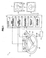
- the medical apparatus 1 includes a processor 6 that performs image processing and the like for the overhead camera section 3, the main camera sections 4 and 5, an overhead monitor 7 that displays an image picked up by the overhead camera section 3 (referred to as overhead image), and a main monitor 8 that displays images picked up by the main camera sections 4 and 5 (referred to as main images).
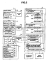
- a processor 6 that performs image processing and the like for the overhead camera section 3, the main camera sections 4 and 5, an overhead monitor 7 that displays an image picked up by the overhead camera section 3 (referred to as overhead image), and a main monitor 8 that displays images picked up by the main camera sections 4 and 5 (referred to as main images).
- the medical apparatus 1 includes a camera operation interface (abbreviated as camera operation I/F) 9 with which a surgeon performs recording of the images picked up by the overhead camera section 3 and the main camera sections 4 and 5 and instruction operation for, for example, movement of image pickup positions and image pickup directions of the main camera sections 4 and 5 to desired places.
- camera operation I/F camera operation interface
- the overhead camera section 3 and the main camera sections 4 and 5 respectively include an overhead camera 3A as first image pickup means and main cameras 4A and 5A as second image pickup means arranged on an inside of an abdomen 2 and a receiving unit 3B and transmitting and receiving units 4B and 5B arranged on an outside of the abdomen 2.
- This embodiment is not limited to such a configuration for transmitting a signal by radio but may be a configuration (e.g., a configuration shown in Fig. 14 ) for extending signal lines respectively from the overhead camera 3A and the main cameras 4A and 5A to connect the overhead camera 3A and the main cameras 4A and 5A to the processor 6 and performing signal transmission by wire.
- a configuration e.g., a configuration shown in Fig. 14
- the receiving unit 3B and the transmitting and receiving units 4B and 5B are unnecessary.
- the configuration including the two main cameras 4A and 5A as the second image pickup means is shown.
- a state in which a lesion part is treated by a treatment instrument can be more surely grasped or recognized than in a case in which one main camera is provided.
- a picked-up image from one direction is obtained.
- picked-up images from different two directions are obtained. Therefore, a state of the treatment instrument can be grasped or recognized in more detail.
- a state of the lesion part can also be grasped or recognized in more detail.
- this embodiment is not limited to the case in which two main cameras are provided but can also be applied to a case in which three or more main cameras are provided or one main camera is provided.
- Operation for fixing the overhead camera 3A and the main cameras 4A and 5A on an inside of the abdomen 2 as shown in Fig. 1 can be performed by using a not-shown endoscope or the like in a puncture hole formed in the abdomen 2 using a trocar 10 by a method disclosed in, for example, Japanese Patent Application Laid-Open Publication No. 2008-307226 .
- a side of the overhead camera 3A and the main cameras 4A and 5A and a side of the receiving unit 3B and the transmitting and receiving units 4B and 5B can be detachably fixed, for example, in a state in which an abdominal wall is held by magnetic force using magnets but may be fixed by other fixing means such as an adhesive.
- Fig. 1 a state in which, after the overhead camera 3A and the main cameras 4A and 5A are fixed on the inside of the abdomen 2, a treatment instrument 19 is inserted through the trocar 10 and treatment is applied to a region (referred to as place) of a treatment target.
- image pickup units 11 a to 11c including an image pickup function, illuminating units 12a to 12c that illuminate a portion where image pickup is performed, and power supply units 13a to 13c including batteries for supplying electric power to the image pickup units 11 a to 11c and the like are respectively housed in armor containers having, for example, a substantially cylindrical shape.
- the overhead camera 3A incorporates a transmission unit 14a and transmits by radio, with the transmission unit 14a, an image signal of an overhead image as a picked-up image picked up by the image pickup unit 11a.
- the receiving unit 3B receives the image signal transmitted by the transmission unit 14a and outputs the image signal to an image processing unit (for overhead) 21 in the processor 6.
- the main cameras 4A and 5A further incorporate transmission and reception units 15b and 15c, camera driving units 16a and 16b, position detecting units 17a and 17b, and identification information generating units (in the figure, abbreviated as ID) 18a and 18b.
- the second main camera 5A has the same configuration as that of the first main camera 4A except that identification information generated by the identification information generating unit 18b is different.
- Fig. 2 an internal configuration is schematically shown.
- the main cameras 4A and 5A transmit image signals of main images as picked-up images respectively picked up by the image pickup units 11b and 11c by radio via the transmission and reception units 15a and 15b (transmitting sections inside).
- the transmitting and receiving units 4B and 5B receive the transmitted image signals and output the image signals to an image processing unit (for main) 22 in the processor 6.
- the transmission and reception units 15a and 15b transmit the image signals with identification information attached thereto.
- the image processing unit (for main) 22 performs management of a main image according to the identification information.
- the main cameras 4A and 5A further include camera driving units 16a and 16b for moving a place whose image is picked up, and position detecting units 17a and 17b that detect driving information (also referred to as setting information) of the camera driving units 16a and 16b that pick up images of the place.
- the overhead camera 3A has a wide-angle observation field of view (e.g., an observation field of view close to 180°).
- the observation field of view of the overhead camera 3A is an overhead image obtained by picking up an inside of an abdominal cavity in a wide range in a view angle state of a wide angle.
- the overhead camera 3A is used in a view angle state of a fixed wide angle.
- main camera images (simplified as indicated by 4A and 5A) obtained by picking up images with the main cameras 4A and 5A in observation fields of view thereof are displayed.
- the main cameras 4A and 5A have a narrower observation field of view (a narrower angle) compared with the overhead camera 3A and can move and set an observation field of view(an image pickup range) with the camera driving units 16a and 16b as explained below.
- the main cameras 4A and 5A can be set in a desired observation field of view in a driving range of the camera driving units 16a and 16b in the abdominal cavity and can be set to a proper image size by the camera driving units 16a and 16b. Therefore, the surgeon can perform observation in detail.
- Fig. 1 shows a display example of, for example, a main image by one main camera 5A.
- the surgeon can survey (look out over) the inside of the abdominal cavity at a wide angle using an overhead image and can observe in detail an arbitrary position with the two main cameras 4A and 5A.
- the camera driving units 16a and 16b include a pan (swinging in a left/right direction) function and a tilt (tilting in an up/down direction) function for the image pickup units 11b and 11c and the illuminating units 12b and 12c and also include a zoom function for enabling enlarged observation by the image pickup units 11b and 11c.
- the camera driving units 16a and 16b can move and set the image pickup units 11b and 11c as image pickup means by panning and tilting the same such that the image pickup units 11b and 11c can pick up images of a desired position.
- the camera driving units 16a and 16b can change, with the zoom function, an angle of view for image pickup, for example, increase image pickup magnification to be larger than that in the case of the overhead camera 3A, and set the image pickup units 11b and 11c in a state in which a lesion of attention or the like can be observed in detail.
- Setting information of pan, tilt, and zoom by the camera driving units 16a and 16b (in other words, information concerning image pickup positions of the image pickup units 11b and 11c, information concerning an image pickup direction, and zoom information of an angle of view of image pickup) is detected by the position detecting units 17a and 17b included in information acquiring means.
- the setting information of the camera driving units 16a and 16b detected by the position detecting units 17a and 17b is recorded in the memory for control 24 as history information together with, for example, a place whose image is picked up by image recording operation by the surgeon (e.g., together with time of instruction operation for a recorded image).
- the surgeon operates a pan SW 9a, a tilt SW 9b, and a zoom SW 9c provided in the camera operation I/F 9, whereby instruction signals for pan, tilt, and zoom are outputted to a CPU for camera driving control (simply abbreviated as CPU) 23 on the inside of the processor 6.
- the CPU 23 performs control of the processor 6, the overhead camera 3A, the main cameras 4A and 5A, and the camera operation I/F 9 included in the medical apparatus 1.
- the CPU 23 generates, with a motor driving signal generating section 23a, motor driving signals corresponding to the instruction signals for pan, tilt, and zoom and performs control for driving the camera driving unit 16a or 16b of the main camera 4A or 5A via the transmitting and receiving unit 4B or 5C.
- the main camera 4A or 5A is set in a state in which the main camera 4A or 5A picks up an image of a place corresponding to the instruction signals.
- the camera driving unit 16a or 16b of the main camera 4A or 5A changes to a (image pickup) setting state for picking up an image of a target place instructed by the surgeon using the camera operation I/F 9.
- the position information acquiring section 23b acquires setting values of pan, tilt, and zoom, in other words, (setting information including) information concerning image pickup positions and image pickup directions and zoom information of the main cameras 4A and 5A from detection signals of pan, tilt, and zoom by the position detecting units 17a and 17b.
- the position information acquiring section 23b records (stores) the setting information of the camera driving units 16a and 16b in the memory for control 24 in time series.
- the setting information may be recorded in a recording section such as a memory of the position information acquiring section 23b instead of the memory for control 24.
- an image recording SW 9d for performing recording instruction operation for an image and an image selection SW 9e for performing image selection for selecting which of main images respectively picked up by the two main cameras 4A and 5A is displayed on the main monitor 8 are provided and an information input section 9f that inputs information is provided according to necessity.
- the camera operation I/F 9 may be configured to be used in common for the main camera 4A and the main camera 5A as shown in Fig. 2 .
- a not-shown selection switch for designating (selecting) the main camera 4A and the main camera 5A is provided.
- a (first) camera operation I/F 9G and a (second) camera operation I/F 9G' for performing operation of pan, tilt, and zoom independently for the main cameras 4A and 5A respectively may be provided as shown in Fig. 1 .
- the surgeon can record an overhead image of the overhead camera 3A and main images of the main cameras 4A and 5A by operating the image recording SW 9d.
- the surgeon After setting a state for picking up an image of a place about to be treated by the main cameras 4A and 5A as explained later with reference to Fig. 3 , in a state in which a distal end of a treatment instrument is set in the place, the surgeon performs the recording operation by the image recording SW 9d. Consequently, the surgeon can record an overhead image and information concerning image pickup position, image pickup directions, and the like of picked-up images of the main cameras 4A and 5A in the overhead image in association with each other (to correspond to each other).
- the processor 6 when instruction operation for image recording is performed by the surgeon via the image recording SW 9d, the processor 6 includes the memory for control 24 as recording means (for history information) for recording, for example, in time series, (information concerning) a place, images of which are picked up by the main cameras 4A and 5A, in an overhead image and image pickup position information and image pickup direction information (i.e., image pickup means setting information) of the main cameras 4A and 5A, which pick up images of the place, in association with each other (to correspond to each other).
- recording means for history information
- recording for recording, for example, in time series, (information concerning) a place, images of which are picked up by the main cameras 4A and 5A, in an overhead image and image pickup position information and image pickup direction information (i.e., image pickup means setting information) of the main cameras 4A and 5A, which pick up images of the place, in association with each other (to correspond to each other).
- the place in this case may be a coordinate (or, for example, place specifying means shown in Fig. 7 similar to the coordinate) for specifying the place, may be an image area of a place whose image is picked up, or may be a coordinate for specifying the image area.
- the (information concerning) the place only has to be information related to the place.
- the overhead image by the overhead camera 3A and the picked-up images of the main cameras 4A and 5A are recorded in time series in association with the place of the image pickup by the main cameras 4A and 5A in the overhead image and a number associated with the place.
- the overhead image is recorded in an image recording section 34a in the image processing unit 21 explained below and the main images are recorded in an image recording section 34b in the image processing unit 22.
- the overhead image and the main images may be recorded in other recording means, for example, the memory for control 24.
- the surgeon can display, for example, a place of image pickup by the main cameras 4A and 5A in a present overhead image with a number affixed to the place by performing, for example, instruction operation for displaying history information (or history) from the information input section 9f (explained later with reference to Fig. 4 ).
- the processor 6 includes a video signal output unit 25 connected to the image processing units 21 and 22.
- the video signal output unit 25 converts image data of an overhead image and main images picked up by the overhead camera 3A and the main camera 4A or 5A and temporarily stored in frame memories for image storage of the image processing units 21 and 22 into video signals of an analog RGB, NTSC/PAL, or IEEE1394 system or the like and output the video signals respectively to the overhead monitor 7 and the main monitor 8.
- the image processing unit 21 includes an image building section 31 a that performs image processing for an image pickup signal (of an overhead image) picked up by the image pickup unit 11a inputted via the receiving unit 3B and builds an overhead image and an image recognition processing section 32a that applies, for example, processing for recognizing a distal end position of the treatment instrument or a place near the distal end position as an image to the overhead image.
- an image building section 31 a that performs image processing for an image pickup signal (of an overhead image) picked up by the image pickup unit 11a inputted via the receiving unit 3B and builds an overhead image
- an image recognition processing section 32a that applies, for example, processing for recognizing a distal end position of the treatment instrument or a place near the distal end position as an image to the overhead image.
- the image processing unit 21 includes an image processing section 33a that performs image processing for superimposing, on the place recognized as the image by the image recognition processing section 32a, a number for specifying the place and an image recording section 34a including a frame memory or the like that records an image image-processed by the image processing section 33a.
- an overhead image generated by the image building section 31 a and information concerning a place superimposed on the overhead image and a number may be recorded in association with each other.
- the image recording section 34a also includes a function of temporarily recording an overhead image to be displayed as a moving image besides an overhead image for which the instruction operation for image recording is performed by the image recording SW 9d.
- the overhead image temporarily recorded in the image recording section 34a or the like is displayed on the overhead monitor 7 through the video signal output unit 25.
- the image recognition processing section 32a performs image recognition processing for setting, for example, a distal end portion of the treatment instrument 19 in a place, images of which are picked up by the main cameras 4A and 5A, in an overhead image and specifying the place, images of which are picked up by the main cameras 4A and 5A, on the overhead image.
- the image recognition processing in this case is used to mean both a case in which the processor 6 side subjectively performs image processing for image recognition and a case in which the surgeon as a subject manually performs instruction operation for image recognition (in this case, the processor 6 performs supplementary processing).
- the image recognition processing may include one of the cases.
- the surgeon After the processing for specifying the place, images of which are picked up by the main cameras 4A and 5A, in the overhead image, the surgeon performs the instruction operation for image recording, whereby, in association with the place specified in the overhead image and a number, setting information of the image pickup of the place by the main cameras 4A and 5A is recorded in the memory for control 24.
- the main cameras 4A and 5A move the places, images of which are picked up by the main cameras 4A and 5A, in the overhead image and the setting information of the place, images of which are also picked up by the main cameras 4A and 5A, in the overhead image in places to which the main cameras 4A and 5A move is recorded in association with each other in time series.
- the information is history information.
- the places can be specified by, for example, numbers.
- instruction operation can be performed to number places on the overhead image using the history information and superimpose and display the places.
- the surgeon performs selection of numbers associated with plural places displayed on the overhead image, whereby the CPU 23 subjects the main cameras 4A and 5A to movement control with the camera driving units 16a and 16b referring to setting information of the places of the numbers and displays main images picked up by the moved and set main cameras 4A and 5A on the main monitor 8.
- the surgeon can quickly check a state of bleeding in more detail from the main images.
- the memory for control 24 forms recording means for storing in advance, in preparation for a case in which a predetermined change such as bleeding occurs in a treated place, in other words, an overhead image, an image area or a coordinate of a place where such a predetermined change is likely to occur.
- the image processing unit 22 includes an image building section 31 b that performs image processing for an image pickup signal (of a main image) picked up by the image pickup unit 11b inputted via the transmitting and receiving unit 4B and builds a main image, an image processing section 33b that performs image processing for superimposing a place and a number for specifying the main image on the main image built by the image building section 31b, and an image recording section 34b including a frame memory and the like that records an image subjected to the image processing by the image processing section 33b.
- setting information such as image pickup positions in which the places to be treatment targets are set as an observation field of view (an image pickup field of view) by the main cameras 4A and 5A is recorded in the memory for control 24 in time series.
- information such as the image pickup positions and the main images are recorded in association with each other.
- the memory for control 24 forms recording means for recording information such as image pickup positions by the main cameras 4A and 5A in the past as history information.
- the CPU 23 when instruction operation for history display is performed by the surgeon from, for example, the information input section 9f, the CPU 23 performs control to read out information concerning places and numbers from the history information stored in the memory for control 24 included in the recording means and display the numbers to be superimposed on the places in the overhead image.
- the CPU 23 has a function of display control means for performing display control for displaying a place recorded in the recording means, i.e., an image area or a coordinate to be superimposed on an overhead image picked up by the overhead camera 3A functioning as the first image pickup means.
- the overhead monitor 7 on which the place recorded in the recording means, in other words, the image area or the coordinate is displayed to be superimposed on the overhead image according to the display control by the display control means forms display means subjected to the display control by the display control means.
- the CPU 23 When a specific number is selected by the surgeon from numbers in the past superimposed and displayed on the overhead monitor 7, the CPU 23 performs control to read out setting information of the main cameras 4A and 5A recorded in association with a place of the number from the memory for control 24 and drive the camera driving units 16a and 16b to cause the main cameras 4A and 5A to pick up images of the place of the selected number.
- the CPU 23 configures movement control means for subjecting, on the basis of setting information such as an image pickup position and an image pickup direction from the memory for control 24, with the camera driving units 16a and 16b, the main cameras 4A and 5A included in the second image pickup means to movement control to pick up the selected place.
- a configuration including the CPU 23 and the camera driving units 16a and 16b may be regarded as the movement control means.
- the movement control means also includes a function of increasing zoom magnification by the main cameras 4A and 5A to increase image pickup magnification.
- the surgeon selects a specific number as explained above, whereby, under the control by the CPU 23, the main cameras 4A and 5A are quickly moved to pick up images of a place of the selected number by the camera driving units 16a and 16b.
- a main image picked up by the main camera 4A or 5A is displayed on the main monitor 8.
- the surgeon checks bleeding or a state close to bleeding in an overhead image.
- the surgeon can check the state quickly and in detail with simple operation using main images by the main cameras 4A and 5A.
- the medical apparatus 1 includes the first image pickup means including, for example, the overhead camera 3A that is fixed to a body wall and picks up an image of an inside of a body cavity, the recording means including, for example, the memory for control 24 that records in advance, in preparation for a case in which a predetermined change occurs, for example, in a first image as an overhead image picked up by the first image pickup means, a predetermined image area in the first image or a coordinate for specifying the predetermined image area, and the display means including, for example, the overhead monitor 7 that displays, in a case in which predetermined change occurs in the first image, the image area or the coordinate recorded by the recording means to be superimposed on the first image picked up by the first pickup means.
- the first image pickup means including, for example, the overhead camera 3A that is fixed to a body wall and picks up an image of an inside of a body cavity
- the recording means including, for example, the memory for control 24 that records in advance, in preparation for a case in which a predetermined change occurs, for example
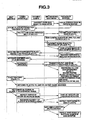
- Fig. 3 shows main operations of the surgeon, the camera operation I/F 9, the overhead camera 3A, the first and second main cameras 4A and 5A, and the processor 6/(the overhead monitor 7 and the main monitor 8).
- an up to down vertical direction indicates elapse of time.
- the surgeon fixes the overhead camera 3A and the main cameras 4A and 5A in the abdominal wall of the abdomen 2. Then, as shown in Fig. 3 , the overhead camera 3A transmits a picked-up overhead image to the processor 6.
- the processor 6 displays the overhead image on the overhead monitor 7.
- the surgeon observes the overhead image and specifies a place necessary for treatment.
- the place is represented as place P1.
- the surgeon operates the camera operation I/F 9 such that images of the place P1 can be picked up by the main cameras 4A and 5A.
- the surgeon operates the pan SW 9a, the tilt SW 9b, and the zoom SW 9c of the camera operation I/F 9. Then, an operation signal of the camera operation I/F 9 is sent to the CPU 23.
- the CPU 23 performs movement instruction to instruct the main cameras 4A and 5A to pick up images of the place P1.
- the CPU 23 drives the camera driving units 16a and 16b.
- the image pickup units 11b and 11c of the main cameras 4A and 5A move (image pickup positions and directions) to pick up images of the place P1.
- a main image set in a state for picking up in detail, at a proper angle of view, the images of the place P1 picked up by the main cameras 4A and 5A is transmitted to the processor 6.
- a main image obtained by picking up an image of the place P1 is displayed on the main monitor 8.
- the surgeon inserts the treatment instrument 19 into an abdominal cavity via the trocar 10.
- the surgeon moves the distal end portion of the treatment instrument 19 to the place P1 that the surgeon desires to treat while looking at the treatment instrument 19 inserted in the abdominal cavity in the overhead image.
- a distal end side of the treatment instrument 19 is displayed on the main monitor 8, on which the place P1 is displayed in detail, together with the place P1 about to be treated.
- a main image on the main monitor 8 shown in Fig. 1 indicates a display example in this case.
- the surgeon determines whether the place P1 is to be recorded.
- the surgeon attempts to perform treatment in this place with the treatment instrument 19, the surgeon performs operation for performing image recording. Specifically, the surgeon operates the image recording SW 9d. According to the operation, pan, tilt, and zoom information (setting information) of the main cameras 4A and 5A is transmitted to the processor 6 together with time (hour) of this recording operation.
- main images of the place P 1 picked up by the main cameras 4A and 5A and the pan, tilt, and zoom information i.e., information concerning image pickup positions and image pickup directions are recorded in association with each other.
- a position of the treatment instrument distal end (or an image area) reflected on the overhead image is, for example, subjected to image recognition (including the case of specific operation by the surgeon) and recorded in the memory for control 24 in association with the place P1.
- the place P1 may be set to automatically affix a number 1 of an initial value according to switch-on of the information input section 9f such that the place P1 in the overhead image can be easily specified from other places.
- the place P1 in the recorded overhead image can be specified by the number 1 and the setting information of the main cameras 4A and 5A that pick up images of the place P1 is recorded as history information (in which treated places are recorded in time series) in association with the place P1 and the number 1 of the overhead image.
- the main images by the main cameras 4A and 5A are also recorded in association with the place P1 and the number 1 (in a state in which identification information is further affixed).
- the surgeon After making it possible to specify the place P1 in this way, as shown in Fig. 3 , the surgeon starts treatment for medical treatment using the treatment instrument 19 in the place P1. After performing the treatment in the place P1, the surgeon moves the place and performs the same processing. In performing the processing, in the same manner as the treatment performed in the place P1, in other places P2 and P3 where treatment is necessary, the surgeon records setting information of the main cameras 4A and 5A in association with the places P2 and P3.
- Fig. 5 shows a main image example displayed on the main monitor 8 while the treatment is performed by the treatment instrument in the place P3.
- a number 3 of the place P3 is displayed on the main monitor 8.
- the treatment is performed by the treatment instrument, for example, in the place P3 in this way, the surgeon could recognize bleeding in the place P1, for example, in a wide-angle overhead image.
- the surgeon Since the overhead image has a wide angle, the surgeon cannot check a state of the bleeding in detail. Therefore, the surgeon performs a display instruction for displaying a history on the overhead image from the information input section 9f.
- the display instruction is input to the CPU 23.
- the CPU 23 reads out information recorded in the memory for control 24 and performs a control operation for display of a history corresponding to the information.
- Fig. 4 shows a display example of the histories. As shown in Fig. 4 , on the overhead image, a number N of a place PN is displayed to be superimposed on the places P1 to P3 recorded in the past. The order of the histories may be displayed as indicated by dotted lines or may be not displayed. Therefore, the surgeon designates (selects) the number 1 from the information input section 9f.
- a signal of this designation is input to the CPU 23 of the processor 6.
- the CPU 23 performs a movement instruction for moving the main cameras 4A and 5A to the place P 1 of the number 1.
- the setting information of the main cameras 4A and 5A is recorded in association with the place P1 of the number 1. Therefore, the CPU 23 drives the camera driving units 16a and 16b according to the setting information.
- the image pickup units 11b and 11c are moved (driven) by pan, tilt, and zoom of the setting information and moved and set in a state for picking up an image of the place P1.
- a main image picked up by the main camera 4A or 5A is displayed on the main monitor 8.
- Fig. 6 shows a display example of the main image in this case. The surgeon can check a bleeding state in detail according to the display of the main image on the main monitor 8. The surgeon quickly performs treatment corresponding to the bleeding state according to a detailed check result.
- the place PN treated in the past where a predetermined change such as bleeding in the overhead image is likely to occur can be recorded as history information in advance in association with the setting information of the main cameras 4A and 5A that pick up images of the place PN and can be displayed on the display means. Therefore, when the surgeon recognizes a predetermined change such as bleeding in the treated place PN in the overhead image, the surgeon can check the place PN quickly and in detail with simple operation.
- this embodiment can reduce, when the surgeon performs a surgical operation, operation performed by the surgeon or the like and can provide the medical apparatus 1 with which the surgeon can more smoothly and easily perform the surgical operation.
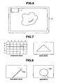
- FIGS. 8 and 9 As an image recognition method by the image recognition processing section 32a, various methods can be used as explained below.
- a left side in Fig. 7 indicates an overhead image and a right side indicates a main image. The same display is shown in FIGS. 8 and 9 .
- FIGS. 10 and 11 an overhead image and a main image are shown in an opposite arrangement.
- the overhead image shown in Fig. 7 is divided into plural image areas designated (specified) by, for example, (i, j) with horizontal 1 to 6 and vertical a to e.
- the overhead image is not limited to be divided into such a number of divisions.
- the surgeon checks in which image area in the overhead image a display image corresponding to a display image (in Fig. 7 , schematically indicated by a triangle) of a main image equivalent to an image pickup place, images of which are picked up by the main cameras 4A and 5A, is present.
- a display image corresponding to a display image in Fig. 7 , schematically indicated by a triangle
- the surgeon designates a place of an image area (5, b).
- the surgeon specifies (recognizes) that the place of the image area (5, b) in the overhead image is an image pickup coordinate or an image pickup place, images of which are picked up by the main cameras 4A and 5A.
- the setting information of the main cameras 4A and 5A is recorded in the memory for control 24 in association with the place PN and the number N.
- Fig. 8 shows a method of specifying an image pickup position of the main cameras 4A and 5A in an overhead image using a reference object such as operation equipment or a treatment instrument.
- a reference object such as operation equipment or a treatment instrument.
- a main image only a vicinity of the distal end portion 19a (schematically indicated by a circle) of the treatment instrument is displayed.
- the treatment instrument is displayed in a wider range.
- a place may be designated as shown in Fig. 7 .
- a position of the main image in the overhead image i.e., an image pickup position of the main cameras 4A and 5A may be specified using an edge image obtained by applying edge treatment to the distal end portion 19a.
- Fig. 9 shows a method of specifying an image pickup position when a light source for irradiating light such as a laser pointer is provided in the main cameras 4A or 5A.
- a light source for irradiating light such as a laser pointer
- a portion irradiated by light 42 of the light source is shown together with an image of the main camera 5A.
- a wavelength of the light 42 is set to wavelength easily distinguished from intra-body illumination light or a shape of the irradiated light is set to be easily distinguished.
- Figs. 7 to 9 a method in which the surgeon designates an image pickup position of the main cameras 4A and 5A on the overhead image is explained.
- image recognition for specifying a relative position with an apparatus such as the image recognition processing section 32a on the processor 6 side may be performed as explained below.
- Fig. 10 shows a method of recognizing, with the image processing section 33b, a characteristic portion of a place of which an image is picked up, in a main image as an image.
- the image processing section 33b recognizes, for example, a shape of a distal end portion of a treatment instrument in the place P1 as an image and sets the recognized image as an image of the number 1 in the place P1.
- a characteristic of the recognized image is sent to the image recognition processing section 32a.
- the image recognition processing section 32a finds an image portion having the characteristic from an overhead image.
- the image recognition processing section 32a determines that a portion having a correlation equal to or larger than a threshold value is present in the overhead image, the image recognition processing section 32a automatically marks the place P1 as a place corresponding to the characteristic portion of the main image and automatically marks a number of the place P1 as 1.
- Fig. 11 shows an image recognition method for specifying an image pickup position of the main camera 4A or 5A using image information of the main camera 4A or 5A reflected on an overhead image.
- a mark 43 is affixed to, for example, an armor container of the main camera 5A reflected on the overhead image. When a direction of the image pickup unit 11b changes, the mark 43 also changes.
- the image recognition processing section 32a estimates an image pickup position of the main camera 5A from a shape of the armor container of the main camera 5A reflected on the overhead image and information concerning the mark 43.
- a distal end portion of an arrow of a dotted line is estimated as the image pickup position of the main camera 5A.
- the place P1 is automatically marked with the specified number 1.
- position sensors may be respectively provided in the overhead camera 3A and the main cameras 4A and 5A and relative positions in both the images may be specified from detection information of the position sensors.
- the overhead camera 3A is in a fixed state, the position sensor may be provided only on the side of the main cameras 4A and 5A.
- the overhead image of the overhead camera 3A is displayed on the overhead monitor 7 using the one overhead camera 3A and the two main cameras 4A and 5A and the main image of selected one main camera of the two main cameras 4A and 5A is displayed on the main monitor 8.
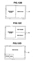
- This embodiment is not limited to a case of such a display form.
- a main image of each of the two main cameras 4A and 5A may be divided into two and displayed on the main monitor 8.
- Two main monitors may be provided to display main images of the main cameras 4A and 5A.
- One monitor 7B may be provided instead of the overhead monitor 7 and the main monitor 8.
- the monitor 7B may be divided into two as shown in Fig. 12B to display an overhead image and a main image of selected one main camera.
- a main image display area in Fig. 12B may be further divided into two to simultaneously display two main images.
- an overhead image and a main image may be displayed as parent and child images or one of the overhead image and the main image may be displayed as a reduced image (a thumbnail image).
- a main image by one main camera is shown in a state displayed as a parent image (an unreduced image)
- the overhead image is shown in a state displayed as a reduced image
- a main image of the other main camera is shown in a state displayed as a reduced image.
- the display of Fig. 12D may be able to be displayed with the parent image and the reduced image interchanged by an image selection switch.
- a medical apparatus may be configured by one overhead camera 3A and one main camera 4A. In this case, the medical apparatus may be configured to use the overhead monitor 7 and the main monitor 8 or may be configured to use one monitor 7B.
- the overhead image and the main image are respectively displayed on the monitors.
- the overhead image and the main image may be displayed as shown in Fig. 12B .
- the main image and the overhead image may be displayed as parent and child images similar to those shown in Fig. 12D .
- Image storing means for storing an overhead image and a main image as thumbnail images and thumbnail display means for displaying the thumbnail images may be provided.
- the thumbnail images may be recorded (stored) in time series or may be recorded only when the surgeon records the thumbnail images.
- selection of recording as an unreduced image and recording as a reduced image may be able to be performed.
- a comment may be able to be recorded in association with the image or may be additionally recorded.
- the place PN treated in the past where a predetermined change such as bleeding is likely to occur in an overhead image can be recorded as history information in advance in association with the setting information of the main cameras 4A and 5A that pickup images of the place and can be displayed on the display means. Therefore, when the surgeon recognizes a predetermined change such as bleeding in the treated place PN in the overhead image, there is an effect that the surgeon can easily check the place PN quickly and in detail with simple operation.
- the surgeon when a situation that the surgeon desires to check such as bleeding occurs in a place treated in the past, the surgeon can perform operation for displaying histories of plural places treated in the past.
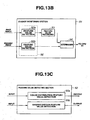
- FIG. 13A shows a medical apparatus 1B according to a modification of the first embodiment.
- a change monitoring section 51 as monitoring means for monitoring (recognizing) whether a predetermined change such as bleeding occurs in an image area portion set in a place treated in the past, is provided.
- the change monitoring section 51 includes a feature value detecting section 52 that detects (extracts), from a past (overhead) image, a feature value of an image area set in a treated place in the image, a feature value recording section 53 that records the detected past feature value, and a determining section (recognizing section) 54 that sets the feature value as reference image data, compares the feature value with a feature value of image data in the same image area in a future (present) overhead image, and determines (or recognizes) presence or absence of (the occurrence of)a predetermined change.
- a feature value detecting section 52 that detects (extracts), from a past (overhead) image, a feature value of an image area set in a treated place in the image
- a feature value recording section 53 that records the detected past feature value
- a determining section (recognizing section) 54 that sets the feature value as reference image data, compares the feature value with a feature value of image data in the same image area in a future (present) overhead image, and determines (
- the images are recorded in the recording means such as the memory for control 24 as past images.
- the images may be recorded according to instruction operation by the surgeon or the movement may be recognized as an image and an image immediately before the movement may be recorded.
- the feature value detecting section 52 is configured by a configuration example including the feature value detecting section 52a that detects a feature value from a past image and the feature value detecting section 52b that detects a feature value from a present image.
- the feature value detecting sections 52a and 52b may be used in common.
- a present state of treatment shown in Fig. 13A is, for example, treatment performed in the place P3
- predetermined image areas R1 and R2 set respectively in the places P1 and P2 in a past overhead image are set.
- the image areas R1 and R2 shown on the overhead image indicate a setting example thereof.
- the image areas R1 and R2 do not always need to be displayed as an image (selection of display may be able to be performed by an option function).
- a feature value extracted in the image area R1 of the past place P1 and a feature value extracted in the image area R2 of the past place P2 are recorded in the feature value recording section 53.
- the determining section 54 determines whether the past feature values and feature values extracted in the same image areas R1 and R2 in an overhead image acquired at present change by an amount equal to or larger than a threshold set in advance.
- the change monitoring section 51 continues the same processing, for example, after a predetermined time interval.
- the determining section 54 outputs a determination result to the CPU 23.
- the CPU 23 displays, for example, a number to be superimposed on a place or an image area corresponding to the determination result in an overhead image displayed at present and informs the surgeon that it is likely that bleeding occurs.
- the CPU 23 controls to move the main cameras 4A and 5A to pick up images of the place.
- the CPU 23 may perform display for requesting the surgeon to confirm whether the surgeon desires to check the place or the image area in more detail or desires to move the main cameras 4A and 5A.
- the CPU 23 controls to move the main cameras 4A and 5A.
- a main image by the main camera 4A or 5A is displayed and the surgeon can check the main image in detail.
- the feature value detecting section 52 (shown in the case in which the feature value detecting section 52a or 52b is used in common) includes a color distribution feature value detecting section 55a that detects a color distribution of an image of an image area as a feature value, for example, as shown in Fig. 13C and a shape/contour feature value detecting section 55b that detects a shape or a contour of the image of the image area as a feature value.
- the determining section 54 compares the feature values and determines presence or absence of a predetermined change such as bleeding. For example, when a place treated and recorded in the past bleeds, a color distribution characteristic of red increases to correspond to the bleeding. Therefore, the determining section 54 can easily determine from a detection output of the color distribution feature value detecting section 55a that the place bleeds.
- the shape/contour feature value detecting section 55b detects the change.
- the determining section 54 determines from an output of the detection that the portion bleeds.
- a feature value of the image area is extracted and recorded, it is monitored whether the feature value temporally changes by an amount equal to or larger than a predetermined threshold, and, when the feature value changes by an amount equal to or larger than the predetermined threshold, the surgeon is informed of the place and the like.
- This modification can provide the medical apparatus 1B in an environment in which the surgeon can easily perform a surgical operation.
- the CPU 23 may be set to perform control to move one of the two main cameras 4A and 5A such that, for example one of the two main cameras 4A and 5A automatically picks up a place where the change occurs.
- the surgeon can quickly check, with one main camera, a state in which a predetermined change such as bleeding occurs. According to a check result, the surgeon may perform instruction operation for returning moved one main camera to a state before the movement or perform instruction operation for moving the other main camera in the same manner as one camera.
- a configuration includes one main camera and an endoscope without including the overhead camera 3A.
- the surgeon can display a past history of images picked up by the main camera.
- the surgeon performs a surgical operation using, for example, the one main camera and the endoscope (a rigid endoscope or a flexible endoscope)
- the surgeon recognizes (finds) a predetermined change such as bleeding in a place treated in the past by the endoscope, the surgeon only has to perform operation for displaying a past history in a main image recorded by the main camera.
- the surgeon specifies a place (or a number) of a reproduced image corresponding to the place where the predetermined change is recognized by the endoscope.
- the surgeon only has to perform instruction operation to move the main camera to the place of the number.
- the main camera quickly moves to the place where the surgeon recognizes the bleeding or the like and displays a picked-up image on the main monitor 8. Therefore, the surgeon can recognize a state of the bleeding or the like in detail.
- the modification is explained in the case of one main camera and the endoscope. However, the modification can be applied in the same manner in a case of two main cameras and an endoscope.
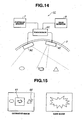
- Fig. 14 shows a medical apparatus 1C according to a second embodiment of the present invention.
- the medical apparatus 1C according to this embodiment includes an overhead camera 3C that picks up an image of an entire inside of an abdominal cavity at a wide angle and a main camera 4C that observes the inside of the abdominal cavity in enlargement, the overhead camera 3C and the main camera 4C being fixed to an abdominal wall of the abdomen 2, a processor 6C, an overhead monitor 7 that displays an overhead image by the overhead camera 3C, the main monitor 8 that displays a main image by the main camera 4C, and a not-shown camera operation I/F.
- the processor 6C is configured to perform transmission of a signal between the overhead camera 3C and the main camera 4C by wire in the processor 6 according to the first embodiment or the processor 6B according to the modification. Further, this embodiment includes functions explained below.
- Fig. 15 shows display images of the overhead monitor 7 and the main monitor 8.
- an enlarged image display range frame (hereinafter simply referred to as display frame) serving as a mark 61 for always showing which part the main camera 4C projects.
- display frame serving as a mark 61 for always showing which part the main camera 4C projects.
- six-axis sensors are mounted on the cameras 3C and 4C.
- the processor 6B can always grasp an image pickup position and an image pickup direction.
- the main camera 4C moves to display the clicked place.
- the place is displayed in enlargement as shown on a right side of Fig. 15 .
- the display range frame serving as the mark 61 moves according to the movement of the main camera 4C.
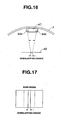
- the main camera 4C can measure a distance between the main camera 4C and a surface 65 of a treatment target organ (place) according to a following procedure by emitting infrared rays from infrared ray emitting sections 64a and 64b provided at both ends of the main camera 4C.
- an inside of an abdominal cavity can be observed through an overhead image and a display range of an enlarged observation image by the main camera 4C is always superimposed on the overhead image. Therefore, a user such as a surgeon can grasp more easily than in the past which part of the entire inside of the abdominal cavity the user is observing.
- the main camera 4C automatically moves and can display the target place.
- An image that the surgeon desires to obtain can be displayed more conveniently and quickly than in the past.
- Fig. 18 shows a medical apparatus 1D.
- the medical apparatus 1D includes an overhead camera 3D that is fixed to an abdominal wall of the abdomen 2 and picks up an image of an entire inside of an abdominal cavity at a wide angle, a processor 6D that performs image processing and the like for the overhead camera 3D, the overhead monitor 7 that displays an overhead image by the overhead camera 3D, and the camera operation I/F 9.
- a monitor (for an enlarged image) 8' (indicated by a dotted line) that displays an enlarged image by electronic zoom may be provided.
- the overhead camera 3D and the processor 6D are shown as a configuration for performing transmission of a signal by wire but may be configured to perform transmission of a signal by radio.
- the overhead camera 3D includes an image pickup unit 11d including a high-resolution image pickup element.
- the image pickup unit 11d picks up an entire inside of an abdominal cavity at a wide angle.
- the processor 6D includes a processing function for applying area selection to an overhead image picked up by the image pickup unit 11d through operation of the camera operation I/F 9 and displaying an area selected by the area selection in enlargement through electronic zoom.
- Fig. 19A shows an overhead image displayed on the overhead monitor 7 in a state in which the electronic zoom is not performed.
- images of a place A and a place B as two area explained later are included.
- Fig. 19B shows an enlarged image in which the place B as a selected area is displayed in enlargement by the electronic zoom.
- the monitor 8' When the monitor 8' is provided, the enlarged image is displayed on the monitor 8'.
- the enlarged image is displayed on the overhead monitor 7.
- This variant is configured to realize, with the high-resolution overhead camera 3D, both a function of an overhead camera that surveys the entire inside of the abdominal cavity and a function similar to the function of the main camera, an image pickup position of which is moved, explained above.
- the processor 6D incorporates the image processing unit 21 including the change monitoring section 51 explained with reference to Fig. 13A .
- the surgeon can apply treatment to a treatment target region in the abdominal cavity with the treatment instrument 10 while observing an overhead image.
- the processor 6D includes the memory for control 24 and the video signal output unit 25 in Fig. 13A .
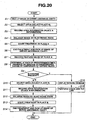
- first step S1 an image of the entire inside of the abdominal cavity is picked up by the overhead camera 3D.
- the processor 6D displays an overhead image on the overhead monitor 7.
- a display example of the overhead image is, for example, as shown in Fig. 19A .
- the surgeon can grasp a state of the entire inside of the abdominal cavity by observing the overhead image.
- step S2 in order to treat the place A, the surgeon selects the place A through operation of area selection of the camera operation I/F 9 to make it possible to observe the place A in more detail in the overhead image shown in Fig. 19A .
- step S3 area information of the selected place A is recorded in the processor 6D.
- step S4 the processor 6D applies processing of electronic zoom for enlarging an image of the place A part to the selected place A.
- Fig. 19B the image part of the place A is displayed in enlargement.
- step S5 The surgeon starts treatment using the treatment instrument 10 as shown in step S5 while observing the enlarged image. Thereafter, when the surgeon ends the treatment, as shown in step S6, the electronic zoom is stopped. As in the case of step S1, an overhead image obtained by picking up an image of the entire inside of the abdominal cavity is displayed on the overhead monitor 7.
- the change monitoring section 51 in the processor 6D records an image (for which the treatment ends) of the place A as a past image and records a feature value of the image (as a reference feature value used for determination of a change).
- step S8 the change monitoring section 51 acquires a feature value of the place A at every predetermined time interval, compares the feature value with the reference feature value, and determines (recognizes) presence or absence of a predetermined change.
- the change monitoring section 51 determines whether, for example, a feature value of a color distribution by the color distribution feature value detecting section 55a and a feature value of a shape or a contour by the shape/contour feature value detecting section 55b change by an amount equal to or larger than a threshold set in advance.
- a temporal spread of a range or an area of the color may be detected. Determination processing for presence or absence of a change at the predetermined time interval in Fig. 8 is shown in step S9.
- step S9 the surgeon continues a surgical operation. For example, when the surgeon attempts to treat another place B different from the place A (according to the same operation as that in the case of step S2), in step S 10, the surgeon performs area selection, i.e., selects the place B in the overhead image shown in Fig. 19A .
- the processor 6D records area information of the selected place B.
- the processor 6D applies processing of electronic zoom for enlarging an image of the place B part to the selected place B.
- step S 13 The surgeon starts treatment using the treatment instrument 10 as shown in step S 13 while observing the enlarged image. Thereafter, when surgeon ends the treatment as shown in step S 14, the electronic zoom is stopped. As in the case of step S1, an overhead image obtained by picking up an image of the entire inside of the abdominal cavity is displayed on the overhead monitor 7.
- step S7 and subsequent step is performed in the same manner (however, the place A in step S7 is read as the place B and the place B in step S10 is read as the place C).
- the processor 6D displays warning information (or notice information) indicating presence of a change on the overhead monitor 7. Specifically, the processor 6D displays warning information indicating that a change such as bleeding from a state immediately after the treatment is present in the place A.
- the surgeon performs a check or the like corresponding to the warning information as shown in step S 16.
- the surgeon can check a state of the place A in response to the warning information and, when treatment is necessary according to a check result, quickly perform the treatment. When treatment is unnecessary, the surgeon can check the unnecessity of treatment.
- the surgeon ends the processing shown in Fig. 20 .
- an overhead image and an enlarged image obtained by enlarging a part of the overhead image can be displayed by one camera (image pickup means) including one high-resolution image pickup unit 11d. Therefore, a surgical operation can be smoothly performed with work simpler than work performed when plural cameras are set in a body cavity.
- Fig. 21 shows a medical apparatus 1E according to a second variant.
- the medical apparatus 1E according to this variant includes first and second main cameras 4E and 5E that are fixed on the abdominal wall of the abdomen 2 and pick up images of an inside of an abdominal cavity respectively at narrow angles, a processor 6E, main monitors 8A and 8B that respectively display main images by the first and second main cameras 4E and 5E, and the camera operation I/F 9.
- the medical apparatus 1E is shown in a configuration example for performing transmission of a signal by wire.
- the first and second main cameras 4E and 5E are image pickup means for enabling change (movement) of an area of which an image is picked up, by pan and tilt and also enabling zoom.
- the first and second main cameras 4E and 5E can be realized by the same configuration as that of the main cameras 4 and 5 shown in Fig. 13A .
- the first and second main cameras 4E and 5E may have a structure in which setting positions in the abdominal cavity of the main cameras 4E and 5E can be moved. In this case, the functions of pan and tile are not always necessary.
- At least one of the main cameras 4E and 5E can be set in a state of a considerably wide angle when zoom is set to minimum magnification.
- one main camera has a function close to an overhead camera.
- One main camera can set an image pickup area of the other main camera in an image pickup area of one main camera and grasp the image pickup area of the other main camera.
- the processor 6E incorporates the image processing unit 22, the CPU for camera driving control 23, the memory for control 24, and the video signal output unit 25.
- the image processing unit 22 shown in Fig. 21 includes the change monitoring section 51 explained with reference to Fig. 13A .
- grasp of position information between the two main cameras 4E and 5E can be performed by the method explained with reference to Figs. 7 to 11 above.
- This variant is a configuration example having functions similar to those in the first variant using the two main cameras 4E and 5E.
- first step S21 the surgeon specifies an area (the place A) where the first main camera 4E is intended to be set and sets the area as an image pickup area of which an image is picked up.
- the surgeon moves and sets the main camera 4E and performs setting of pan, tilt, and the like such that the main camera 4E can pick up an image of the place A to be treated.
- step S22 concerning the second main camera 5E, the surgeon also sets the place A to be treated to be included in an image pickup area.
- the setting of the main camera 5E may be automatically performed using, for example, relative position information with the main camera 4E and shape recognition for an object such as the distal end portion of the treatment instrument 10 set in the place A to be treated.
- next step S23 the processor 6E records area information (information concerning the place A) of the main cameras 4E and 5E.
- next step S24 the surgeon starts treatment using the treatment instrument 10 in the place A.
- the surgeon performs the treatment while observing main images picked up by the main cameras 4E and 5E. Then, the surgeon ends the treatment in the place A.
- step S25 the processor 6E records an image of the place A, for which the treatment ends, as a past image.
- the change monitoring section 51 records a feature value of the place A as a reference feature value.
- the change monitoring section 51 acquires a feature value of the place A at every predetermined time interval, compares the feature value with the reference feature value, and determines (recognizes) presence or absence of a predetermined change.
- the change monitoring section 51 determines whether, for example, a feature value of a color distribution by the color distribution feature value detecting section 55a and a feature value of a shape or a contour by the shape/contour feature value detecting section 55b change by an amount equal to or larger than a threshold set in advance. Determination processing for presence or absence of a change at the predetermined time interval in Fig. 22 is shown in step S27.
- the surgeon continues a surgical operation. For example, when the surgeon attempts to treat another place B different from the place A, in step S28, the surgeon specifies the place B and sets the main camera 4E to pick up an image of the place B. A main image by the main camera 4E is displayed on the main monitor 8A.
- step S29 the surgeon sets the main camera 5E to pickup an image of the place B.
- a main image by the main camera 5E is displayed on the main monitor 8B.
- step S30 the main camera 5E is set in a state in which the main camera 5E picks up an image of the place A at a predetermined time interval.
- the surgeon starts treatment using the treatment instrument 10 as shown in step S31 while observing the main image. Thereafter, the surgeon ends the treatment, as shown in step S32.
- step S33 the processor 6E displays warning information (or notice information) indicating presence of a change on the overhead monitor 8A or the like.
- the surgeon performs a check or the like corresponding to the warning information as shown in step S34.
- the surgeon can check a state of the place A in response to the warning information and, when treatment is necessary according to a check result, quickly perform the treatment. When treatment is unnecessary, the surgeon can check the unnecessity of treatment.
- the surgeon ends the processing shown in Fig. 22 .
- effects substantially the same as those in the modification of the first embodiment can be obtained.
- the effects substantially the same as those in the modification of the first embodiment can be obtained by using two cameras (image pickup means). Therefore, the surgeon can smoothly perform a surgical operation with simple work.
Landscapes
- Engineering & Computer Science (AREA)
- Health & Medical Sciences (AREA)
- Life Sciences & Earth Sciences (AREA)
- Physics & Mathematics (AREA)
- Surgery (AREA)
- Radiology & Medical Imaging (AREA)
- General Health & Medical Sciences (AREA)
- Medical Informatics (AREA)
- Nuclear Medicine, Radiotherapy & Molecular Imaging (AREA)
- Heart & Thoracic Surgery (AREA)
- Computer Vision & Pattern Recognition (AREA)
- Biomedical Technology (AREA)
- Optics & Photonics (AREA)
- Biophysics (AREA)
- Molecular Biology (AREA)
- Animal Behavior & Ethology (AREA)
- Theoretical Computer Science (AREA)
- Public Health (AREA)
- Veterinary Medicine (AREA)
- Pathology (AREA)
- General Physics & Mathematics (AREA)
- Signal Processing (AREA)
- Quality & Reliability (AREA)
- Endoscopes (AREA)
Claims (13)
- Medizinisches Gerät (1; 1B; 1C; 1D; 1E), das umfasst:einen Overhead-Kameraabschnitt (3; 3C; 3D; 4E), der dazu eingerichtet ist, an einer Bauchdecke (2) eines lebenden Körpers fixiert zu werden, und der dazu eingerichtet ist, ein Overheadbild eines Inneren der Bauchhöhle unter einem Weitwinkel aufzunehmen;mindestens einen Hauptkameraabschnitt (4, 5; 4C; 4E, 5E), der durch Schwenken und Kippen bewegbar ist und der dazu eingerichtet ist, an der Bauchdecke fixiert zu werden und Bilder des Inneren der Bauchhöhle unter engeren Winkeln aufzunehmen als der Overhead-Kameraabschnitt (3; 3C; 3D; 4E);mindestens eine Kameraantriebseinheit (16a, 16b), die dazu eingerichtet ist, einen Ort zu bewegen, dessen Bild durch den mindestens einen Hauptkameraabschnitt (4, 5; 4C; 4E, 5E) aufgenommen wird, wobei die mindestens eine Kameraantriebseinheit (16a, 16b) eine Schwenkfunktion, eine Kippfunktion und eine Zoomfunktion hat;eine Kamerabetätigungsschnittstelle (9), die dazu eingerichtet ist, Befehlssignale zum Schwenken, Kippen, und Zoomen auszugeben;Positionserfassungseinheiten (17a, 17b), die dazu eingerichtet sind, durch Erfassen einer Einstellinformation zum Schwenken, Kippen und Zoomen durch die Kameraantriebseinheiten (16a, 16b) eine Information bezüglich Bildaufnahmepositionen zu erfassen;einen Positionsinformationsaufnahmeabschnitt (23b), der dazu eingerichtet ist, die Einstellinformation aufzuzeichnen;einen Aufzeichnungsabschnitt (24, 34a, 34b), der dazu eingerichtet ist, das Overheadbild und eine Information bezüglich Bildaufnahmepositionen von aufgenommenen Bildern des mindestens einen Hauptkameraabschnitts (4, 5) in dem Overheadbild und die Positionen bezüglich eines Orts, von dem durch den mindestens einen Hauptkameraabschnitt (4, 5) Bilder aufgenommen werden, in dem Overheadbild aufzuzeichnen; undein Anzeigesteuerungsmittel (21, 23), das dazu eingerichtet ist, eine Anzeige (7, 8, 7B; 8A, 8B) zu steuern, um den aufgezeichneten Ort dem Overheadbild überlagert anzuzeigen.
- Medizinisches Gerät gemäß Anspruch 1, das ferner ein Behandlungsinstrument (19) zum Durchführen einer Behandlung in einem Bildaufnahmebereich des Overhead-Kameraabschnitts (3; 3C; 3D; S1, 4E; 5E) umfasst.
- Medizinisches Gerät gemäß Anspruch 1, wobei das Anzeigesteuerungsmittel (21, 23) dazu eingerichtet ist, eine Anzeige (7, 8, 7B; 8A, 8B) zu steuern, um auf einem Bildschirm das durch den Overhead-Kameraabschnitt (3; 3C; 3D; S1, 4E; 5E) aufgenommene Overheadbild und das durch den mindestens einen Hauptkameraabschnitt (4, 5; 4C; S4; 4E, SE) aufgenommene Bild aufgeteilt anzuzeigen.
- Medizinisches Gerät gemäß Anspruch 1, wobei das Anzeigesteuerungsmittel (21, 23) dazu eingerichtet ist, in einer Reduzierung auf einem Bildschirm das von dem Overhead-Kameraabschnitt (3; 3C; 3D; S1, 4E; 5E) aufgenommene Overheadbild oder das von dem mindestens einen Hauptkameraabschnitt (4, 5; 4C; S4; 4E, SE) aufgenommene Bild anzuzeigen.
- Medizinisches Gerät gemäß Anspruch 1, wobei das medizinische Gerät (1; 1B; 1C; 1D; 1E) dazu eingerichtet ist, bei einer Aufzeichnung des Bildbereichs oder der Koordinate in dem Aufzeichnungsabschnitt (24, 34a, 34b) vorab das durch den mindestens einen Hauptkameraabschnitt (4, 5; 4C; S4; 4E, SE) aufgenommene Bild, die Information bezüglich der Bildaufnahmeposition und die Information bezüglich der Bildaufnahmerichtung des mindestens einen Hauptkameraabschnitts (4, 5) in Verbindung mit dem Bildbereich oder der Koordinate in einem Zustand, in dem der Bildbereich oder die Koordinate in eine Bildaufnahmeposition gesetzt wird, deren Bild durch den mindestens einen Hauptkameraabschnitt (4, 5; 4C; S4; 4E, SE) aufgenommen wird, aufzuzeichnen.
- Medizinisches Gerät gemäß Anspruch 1, wobei das medizinische Gerät (1; 1B; 1C; 1D; 1E) dazu eingerichtet ist, wenn eine Befehlsbetätigung zum Anzeigen des Bildbereichs oder der Koordinate, der/die dem durch den Overhead-Kameraabschnitt (3; 3C; 3D; S1, 4E; 5E) aufgenommene Overheadbild zu überlagern ist, erfolgt, eine in dem Aufzeichnungsabschnitt (24, 34a, 34b) aufgezeichnete Vergangenheitsinformation des Bildbereichs oder der Koordinate vor der Befehlsbetätigung anzuzeigen.
- Medizinisches Gerät gemäß Anspruch 1 oder Anspruch 2, das ferner einen Überwachungsabschnitt (32a; 51) umfasst, der dazu eingerichtet ist, zu überwachen, ob in einer Bildinformation eines aktuellen Bildbereichs, der einem in dem Aufzeichnungsabschnitt (24, 34a, 34b) aufgezeichneten früheren Bildbereich entspricht, eine Bildänderung von einer Bildinformation des früheren Bildbereichs auftritt,
wobei der Überwachungsabschnitt (32a; 51) einen Merkmalswerterfassungsabschnitt (52), der dazu eingerichtet ist, einen ersten Merkmalswert eines Bilds des früheren Bildbereichs und einen zweiten Merkmalswert eines Bild des aktuellen Bildbereichs zu erfassen, und einen Bestimmungsabschnitt (54) umfasst, der dazu eingerichtet ist, den ersten Merkmalswert und den zweiten Merkmalswert zu vergleichen und das Auftreten einer Bildänderung zu bestimmen. - Medizinisches Gerät gemäß Anspruch 7, wobei der Überwachungsabschnitt (32a; 51) dazu eingerichtet ist, zu überwachen ob eine Blutung, die gleich einem oder größer als ein Schwellwert ist, als die Bildänderung auftritt.
- Medizinisches Gerät gemäß Anspruch 7 oder Anspruch 8, wobei der Überwachungsabschnitt (32a; 51) dazu eingerichtet ist, eine Steuerung auszuführen, um den mindestens einen Hauptkameraabschnitt (4, 5; 4C; S4; 4E, SE) so zu bewegen, dass der mindestens eine Hauptkameraabschnitt (4, 5; 4C; S4; 4E, SE) ein Bild eines Bildbereichs aufnimmt, in dem bestimmt wird, dass die Bildänderung auftritt, wenn der Überwachungsabschnitt (32a; 51) bestimmt, dass die Bildänderung auftritt.
- Medizinisches Gerät gemäß Anspruch 9, wobei der Überwachungsabschnitt (32a; 51) dazu eingerichtet ist, eine Steuerung auszuführen, um den mindestens einen Hauptkameraabschnitt (4, 5; 4C; S4; 4E, SE) so zu bewegen, dass der mindestens eine Hauptkameraabschnitt (4, 5; 4C; S4; 4E, SE) ein Bild eines Bildbereichs aufnimmt, in dem bestimmt wird, dass die Blutung auftritt, wenn der Überwachungsabschnitt (32a; 51) bestimmt, dass eine Blutung, die gleich einem oder größer als ein Schwellwert ist, als die Bildänderung von der Bildinformation des in dem Aufzeichnungsabschnitt (24, 34a, 34b) aufgezeichneten früheren Bildbereichs am Ende einer Behandlung eines Behandlungsinstruments zur Durchführung der Behandlung auftritt.
- Medizinisches Gerät gemäß Anspruch 8, wobei der Überwachungsabschnitt (32a; 51) einen Merkmalswerterfassungsabschnitt (52), der dazu eingerichtet ist, einen ersten Merkmalswert eines Bilds des früheren Bildbereichs und einen zweiten Merkmalswert eines Bild des aktuellen Bildbereichs zu erfassen, und einen Bestimmungsabschnitt (54) umfasst, der dazu eingerichtet ist, den ersten Merkmalswert und den zweiten Merkmalswert zu vergleichen und das Auftreten einer Blutung als die Bildänderung zu bestimmen.
- Medizinisches Gerät gemäß Anspruch 7, wobei der Merkmalswerterfassungsabschnitt (52) einen Farbverteilungsmerkmalswerterfassungsabschnitt (55a), der dazu eingerichtet ist, einen Farbverteilungsmerkmalswert in einem Bild des früheren Bildbereichs und einen Farbverteilungsmerkmalswert in einem Bild des aktuellen Bildbereichs zu erfassen, oder einen Form/Konturmerkmalswerterfassungsabschnitt umfasst, der dazu eingerichtet ist, einen Merkmalswert einer Form oder einer Kontur in dem Bild des früheren Bildbereichs und einen Merkmalswert einer Form oder einer Kontur in dem Bild des aktuellen Bildbereichs zu erfassen.
- Medizinisches Gerät gemäß einem der vorhergehenden Ansprüche,das zwei Hauptkameraabschnitte (4, 5; 4C; S4; 4E, SE) umfasst.
Applications Claiming Priority (2)
| Application Number | Priority Date | Filing Date | Title |
|---|---|---|---|
| JP2010108425 | 2010-05-10 | ||
| PCT/JP2011/058317 WO2011142189A1 (ja) | 2010-05-10 | 2011-03-31 | 医療装置 |
Publications (3)
| Publication Number | Publication Date |
|---|---|
| EP2425761A1 EP2425761A1 (de) | 2012-03-07 |
| EP2425761A4 EP2425761A4 (de) | 2012-03-28 |
| EP2425761B1 true EP2425761B1 (de) | 2015-12-30 |
Family
ID=44914245
Family Applications (1)
| Application Number | Title | Priority Date | Filing Date |
|---|---|---|---|
| EP11780446.8A Not-in-force EP2425761B1 (de) | 2010-05-10 | 2011-03-31 | Medizinische vorrichtung |
Country Status (4)
| Country | Link |
|---|---|
| US (1) | US8355043B2 (de) |
| EP (1) | EP2425761B1 (de) |
| JP (1) | JP4861540B2 (de) |
| WO (1) | WO2011142189A1 (de) |
Families Citing this family (23)
| Publication number | Priority date | Publication date | Assignee | Title |
|---|---|---|---|---|
| EP2829218B1 (de) * | 2012-03-17 | 2017-05-03 | Waseda University | Bildvervollständigungssystem für einen bildausschnittbereich, bildverarbeitungsvorrichtung und programm dafür |
| WO2014002565A1 (ja) * | 2012-06-26 | 2014-01-03 | ソニー株式会社 | 撮像制御装置、記憶システムおよび記憶媒体 |
| CN104487014B (zh) | 2012-07-25 | 2017-10-27 | 直观外科手术操作公司 | 手术系统中有效的交互式出血检测 |
| US10110785B2 (en) * | 2012-08-10 | 2018-10-23 | Karl Storz Imaging, Inc. | Deployable imaging system equipped with solid state imager |
| DE102012025100A1 (de) * | 2012-12-20 | 2014-06-26 | avateramedical GmBH | Entkoppeltes Mehrkamerasystem für die minimal-invasive Chirurgie |
| WO2015020093A1 (ja) * | 2013-08-08 | 2015-02-12 | オリンパスメディカルシステムズ株式会社 | 手術画像観察装置 |
| EP3110305B1 (de) * | 2014-02-27 | 2021-09-01 | University Surgical Associates, Inc. | Interaktive anzeige für chirurgie |
| KR20160032586A (ko) * | 2014-09-16 | 2016-03-24 | 삼성전자주식회사 | 관심영역 크기 전이 모델 기반의 컴퓨터 보조 진단 장치 및 방법 |
| EP3187096B1 (de) | 2014-11-06 | 2021-09-08 | Sony Group Corporation | Endoskopische vorrichtung, verfahren zur steuerung einer endoskopischen vorrichtung und programm |
| JP6485694B2 (ja) * | 2015-03-26 | 2019-03-20 | ソニー株式会社 | 情報処理装置および方法 |
| JP6629047B2 (ja) * | 2015-11-13 | 2020-01-15 | 国立大学法人千葉大学 | 画像合成装置および画像合成装置の作動方法 |
| DE102016100566B4 (de) | 2016-01-14 | 2024-05-23 | Carl Zeiss Meditec Ag | Assistenzsystem für ein medizinisch optisches Beobachtungsgerät und Verfahren zum Verbessern der Sichtbarkeit einer Blutaustrittsstelle in einem mit einem medizinisch optischen Beobachtungsgerät gewonnenen Bild und medizinisch optisches Beobachtungsgerätesystem |
| WO2017138208A1 (ja) | 2016-02-10 | 2017-08-17 | オリンパス株式会社 | 内視鏡システム |
| JP6785941B2 (ja) * | 2017-03-01 | 2020-11-18 | 富士フイルム株式会社 | 内視鏡システム及びその作動方法 |
| JP6818142B2 (ja) * | 2017-06-30 | 2021-01-20 | シャープ株式会社 | 内視鏡装置、内視鏡システム、投光装置、および流体処理装置 |
| JP7240913B2 (ja) * | 2019-03-18 | 2023-03-16 | 株式会社キーエンス | 画像測定装置 |
| CA3143175A1 (en) * | 2019-08-06 | 2021-02-11 | Alcon Inc. | Scene camera systems and methods for vitreoretinal surgery |
| WO2021152785A1 (ja) * | 2020-01-30 | 2021-08-05 | 株式会社インキュビット | 動画再生システム |
| US12042944B2 (en) * | 2020-03-30 | 2024-07-23 | Depuy Ireland Unlimited Company | Robotic surgical system with graphical user interface |
| JP7658724B2 (ja) * | 2020-06-29 | 2025-04-08 | キヤノンメディカルシステムズ株式会社 | 手術支援システム及び支援システムの作動方法 |
| US20230110791A1 (en) * | 2021-09-29 | 2023-04-13 | Cilag Gmbh International | Instrument Control Imaging Systems for Visualization of Upcoming Surgical Procedure Steps |
| US20230107857A1 (en) | 2021-09-29 | 2023-04-06 | Cilag Gmbh International | Surgical sealing devices for a natural body orifice |
| JP7417331B1 (ja) * | 2023-04-21 | 2024-01-18 | 株式会社Asue | 画像処理装置およびカメラシステム |
Citations (2)
| Publication number | Priority date | Publication date | Assignee | Title |
|---|---|---|---|---|
| US20070255100A1 (en) * | 2006-01-06 | 2007-11-01 | Olympus Medical Systems Corporation | Medical method and medical system conducted percutaneous or using naturally occurring body orifice |
| WO2008006180A1 (en) * | 2006-07-10 | 2008-01-17 | Katholieke Universiteit Leuven | Endoscopic vision system |
Family Cites Families (18)
| Publication number | Priority date | Publication date | Assignee | Title |
|---|---|---|---|---|
| US5846185A (en) * | 1996-09-17 | 1998-12-08 | Carollo; Jerome T. | High resolution, wide field of view endoscopic viewing system |
| JP3955126B2 (ja) * | 1997-05-14 | 2007-08-08 | オリンパス株式会社 | 内視鏡の視野変換装置 |
| US6930705B2 (en) * | 2000-11-14 | 2005-08-16 | Pentax Corporation | Image search device |
| JP4493386B2 (ja) * | 2003-04-25 | 2010-06-30 | オリンパス株式会社 | 画像表示装置、画像表示方法および画像表示プログラム |
| JP2005319086A (ja) | 2004-05-10 | 2005-11-17 | Fujinon Corp | 体腔内観察システム |
| JP2006223375A (ja) * | 2005-02-15 | 2006-08-31 | Olympus Corp | 手術データ記録装置、手術データ表示装置及び手術データ記録表示方法 |
| JP4418400B2 (ja) | 2005-05-20 | 2010-02-17 | オリンパスメディカルシステムズ株式会社 | 画像表示装置 |
| US8491464B2 (en) * | 2005-07-08 | 2013-07-23 | Olympus Corporation | In-vivo information acquiring apparatus, in-vivo information acquiring system, and in-vivo information acquiring method |
| US20070060798A1 (en) * | 2005-09-15 | 2007-03-15 | Hagai Krupnik | System and method for presentation of data streams |
| CN101947114B (zh) * | 2005-12-28 | 2011-11-16 | 奥林巴斯医疗株式会社 | 图像处理装置和该图像处理装置中的图像处理方法 |
| JP5131951B2 (ja) | 2006-02-21 | 2013-01-30 | 富士フイルム株式会社 | 体腔内観察装置 |
| JP5121204B2 (ja) * | 2006-10-11 | 2013-01-16 | オリンパス株式会社 | 画像処理装置、画像処理方法、および画像処理プログラム |
| JP2008307226A (ja) * | 2007-06-14 | 2008-12-25 | Olympus Medical Systems Corp | 内視鏡システム |
| JP4472728B2 (ja) * | 2007-06-14 | 2010-06-02 | オリンパスメディカルシステムズ株式会社 | 内視鏡システム |
| JP4472727B2 (ja) * | 2007-06-14 | 2010-06-02 | オリンパスメディカルシステムズ株式会社 | 内視鏡装置 |
| US7666181B2 (en) * | 2008-08-02 | 2010-02-23 | Tarek Ahmed Nabil Abou El Kheir | Multi-purpose minimally invasive instrument that uses a micro entry port |
| JP5250391B2 (ja) | 2008-10-31 | 2013-07-31 | セコム株式会社 | 取引監視装置 |
| JP2011036372A (ja) * | 2009-08-10 | 2011-02-24 | Tohoku Otas Kk | 医療画像記録装置 |
-
2011
- 2011-03-31 WO PCT/JP2011/058317 patent/WO2011142189A1/ja not_active Ceased
- 2011-03-31 JP JP2011537782A patent/JP4861540B2/ja not_active Expired - Fee Related
- 2011-03-31 EP EP11780446.8A patent/EP2425761B1/de not_active Not-in-force
- 2011-09-08 US US13/227,773 patent/US8355043B2/en not_active Expired - Fee Related
Patent Citations (2)
| Publication number | Priority date | Publication date | Assignee | Title |
|---|---|---|---|---|
| US20070255100A1 (en) * | 2006-01-06 | 2007-11-01 | Olympus Medical Systems Corporation | Medical method and medical system conducted percutaneous or using naturally occurring body orifice |
| WO2008006180A1 (en) * | 2006-07-10 | 2008-01-17 | Katholieke Universiteit Leuven | Endoscopic vision system |
Also Published As
| Publication number | Publication date |
|---|---|
| US20120062717A1 (en) | 2012-03-15 |
| JP4861540B2 (ja) | 2012-01-25 |
| EP2425761A4 (de) | 2012-03-28 |
| JPWO2011142189A1 (ja) | 2013-07-22 |
| US8355043B2 (en) | 2013-01-15 |
| WO2011142189A1 (ja) | 2011-11-17 |
| EP2425761A1 (de) | 2012-03-07 |
Similar Documents
| Publication | Publication Date | Title |
|---|---|---|
| EP2425761B1 (de) | Medizinische vorrichtung | |
| EP4062420B1 (de) | Interaktive informationsauflage auf mehreren chirurgischen displays | |
| US11748924B2 (en) | Tiered system display control based on capacity and user operation | |
| US11992372B2 (en) | Cooperative surgical displays | |
| EP3914139B1 (de) | Erweiterte medizinische sehsysteme und verfahren | |
| EP3603510B1 (de) | Effiziente und interaktive blutungsdetektion in einem chirurgischen system | |
| RU2434600C2 (ru) | Хирургическая система, управляемая по изображениям | |
| JP2020073083A (ja) | 波長帯選択による画像化を用いた尿管検出 | |
| US20130046137A1 (en) | Surgical instrument and method with multiple image capture sensors | |
| WO2017159335A1 (ja) | 医療用画像処理装置、医療用画像処理方法、プログラム | |
| WO2015049962A1 (ja) | 内視鏡システム | |
| JPWO2018168261A1 (ja) | 制御装置、制御方法、及びプログラム | |
| CN103491848A (zh) | 医疗用内窥镜系统 | |
| JPWO2015046152A1 (ja) | 内視鏡システム | |
| WO2019036318A2 (en) | METHOD FOR SPATIAL LOCATION OF POINTS OF INTEREST DURING SURGICAL INTERVENTION | |
| US12183448B2 (en) | Medical image processing apparatus, trocar, medical observation system, image processing method, and computer readable recording medium | |
| JP7544033B2 (ja) | 医療システム、情報処理装置及び情報処理方法 | |
| US20190335104A1 (en) | Image processing apparatus, image processing method, and optical member | |
| KR102313319B1 (ko) | 증강현실 대장 내시경 시스템 및 이를 이용한 모니터링 방법 | |
| US20250268454A1 (en) | Surgical assistance system and surgical assistance device | |
| JP4417877B2 (ja) | 光送受信装置制御システム |
Legal Events
| Date | Code | Title | Description |
|---|---|---|---|
| PUAI | Public reference made under article 153(3) epc to a published international application that has entered the european phase |
Free format text: ORIGINAL CODE: 0009012 |
|
| 17P | Request for examination filed |
Effective date: 20111201 |
|
| AK | Designated contracting states |
Kind code of ref document: A1 Designated state(s): AL AT BE BG CH CY CZ DE DK EE ES FI FR GB GR HR HU IE IS IT LI LT LU LV MC MK MT NL NO PL PT RO RS SE SI SK SM TR |
|
| RAP1 | Party data changed (applicant data changed or rights of an application transferred) |
Owner name: OLYMPUS MEDICAL SYSTEMS CORP. |
|
| A4 | Supplementary search report drawn up and despatched |
Effective date: 20120229 |
|
| RIC1 | Information provided on ipc code assigned before grant |
Ipc: A61B 1/313 20060101AFI20120223BHEP Ipc: A61B 1/00 20060101ALI20120223BHEP |
|
| 17Q | First examination report despatched |
Effective date: 20130521 |
|
| DAX | Request for extension of the european patent (deleted) | ||
| REG | Reference to a national code |
Ref country code: DE Ref legal event code: R079 Ref document number: 602011022317 Country of ref document: DE Free format text: PREVIOUS MAIN CLASS: A61B0001313000 Ipc: G06T0007000000 |
|
| GRAP | Despatch of communication of intention to grant a patent |
Free format text: ORIGINAL CODE: EPIDOSNIGR1 |
|
| RIC1 | Information provided on ipc code assigned before grant |
Ipc: G06T 7/00 20060101AFI20150609BHEP |
|
| INTG | Intention to grant announced |
Effective date: 20150709 |
|
| RAP1 | Party data changed (applicant data changed or rights of an application transferred) |
Owner name: OLYMPUS CORPORATION |
|
| GRAS | Grant fee paid |
Free format text: ORIGINAL CODE: EPIDOSNIGR3 |
|
| GRAA | (expected) grant |
Free format text: ORIGINAL CODE: 0009210 |
|
| AK | Designated contracting states |
Kind code of ref document: B1 Designated state(s): AL AT BE BG CH CY CZ DE DK EE ES FI FR GB GR HR HU IE IS IT LI LT LU LV MC MK MT NL NO PL PT RO RS SE SI SK SM TR |
|
| REG | Reference to a national code |
Ref country code: GB Ref legal event code: FG4D |
|
| REG | Reference to a national code |
Ref country code: CH Ref legal event code: EP |
|
| REG | Reference to a national code |
Ref country code: AT Ref legal event code: REF Ref document number: 767779 Country of ref document: AT Kind code of ref document: T Effective date: 20160115 |
|
| REG | Reference to a national code |
Ref country code: IE Ref legal event code: FG4D |
|
| REG | Reference to a national code |
Ref country code: DE Ref legal event code: R096 Ref document number: 602011022317 Country of ref document: DE |
|
| REG | Reference to a national code |
Ref country code: LT Ref legal event code: MG4D |
|
| PG25 | Lapsed in a contracting state [announced via postgrant information from national office to epo] |
Ref country code: HR Free format text: LAPSE BECAUSE OF FAILURE TO SUBMIT A TRANSLATION OF THE DESCRIPTION OR TO PAY THE FEE WITHIN THE PRESCRIBED TIME-LIMIT Effective date: 20151230 Ref country code: LT Free format text: LAPSE BECAUSE OF FAILURE TO SUBMIT A TRANSLATION OF THE DESCRIPTION OR TO PAY THE FEE WITHIN THE PRESCRIBED TIME-LIMIT Effective date: 20151230 Ref country code: NO Free format text: LAPSE BECAUSE OF FAILURE TO SUBMIT A TRANSLATION OF THE DESCRIPTION OR TO PAY THE FEE WITHIN THE PRESCRIBED TIME-LIMIT Effective date: 20160330 |
|
| REG | Reference to a national code |
Ref country code: NL Ref legal event code: MP Effective date: 20151230 |
|
| REG | Reference to a national code |
Ref country code: AT Ref legal event code: MK05 Ref document number: 767779 Country of ref document: AT Kind code of ref document: T Effective date: 20151230 |
|
| PG25 | Lapsed in a contracting state [announced via postgrant information from national office to epo] |
Ref country code: RS Free format text: LAPSE BECAUSE OF FAILURE TO SUBMIT A TRANSLATION OF THE DESCRIPTION OR TO PAY THE FEE WITHIN THE PRESCRIBED TIME-LIMIT Effective date: 20151230 Ref country code: GR Free format text: LAPSE BECAUSE OF FAILURE TO SUBMIT A TRANSLATION OF THE DESCRIPTION OR TO PAY THE FEE WITHIN THE PRESCRIBED TIME-LIMIT Effective date: 20160331 Ref country code: SE Free format text: LAPSE BECAUSE OF FAILURE TO SUBMIT A TRANSLATION OF THE DESCRIPTION OR TO PAY THE FEE WITHIN THE PRESCRIBED TIME-LIMIT Effective date: 20151230 Ref country code: LV Free format text: LAPSE BECAUSE OF FAILURE TO SUBMIT A TRANSLATION OF THE DESCRIPTION OR TO PAY THE FEE WITHIN THE PRESCRIBED TIME-LIMIT Effective date: 20151230 Ref country code: FI Free format text: LAPSE BECAUSE OF FAILURE TO SUBMIT A TRANSLATION OF THE DESCRIPTION OR TO PAY THE FEE WITHIN THE PRESCRIBED TIME-LIMIT Effective date: 20151230 |
|
| PG25 | Lapsed in a contracting state [announced via postgrant information from national office to epo] |
Ref country code: NL Free format text: LAPSE BECAUSE OF FAILURE TO SUBMIT A TRANSLATION OF THE DESCRIPTION OR TO PAY THE FEE WITHIN THE PRESCRIBED TIME-LIMIT Effective date: 20151230 |
|
| PG25 | Lapsed in a contracting state [announced via postgrant information from national office to epo] |
Ref country code: ES Free format text: LAPSE BECAUSE OF FAILURE TO SUBMIT A TRANSLATION OF THE DESCRIPTION OR TO PAY THE FEE WITHIN THE PRESCRIBED TIME-LIMIT Effective date: 20151230 Ref country code: CZ Free format text: LAPSE BECAUSE OF FAILURE TO SUBMIT A TRANSLATION OF THE DESCRIPTION OR TO PAY THE FEE WITHIN THE PRESCRIBED TIME-LIMIT Effective date: 20151230 Ref country code: IT Free format text: LAPSE BECAUSE OF FAILURE TO SUBMIT A TRANSLATION OF THE DESCRIPTION OR TO PAY THE FEE WITHIN THE PRESCRIBED TIME-LIMIT Effective date: 20151230 |
|
| PG25 | Lapsed in a contracting state [announced via postgrant information from national office to epo] |
Ref country code: SK Free format text: LAPSE BECAUSE OF FAILURE TO SUBMIT A TRANSLATION OF THE DESCRIPTION OR TO PAY THE FEE WITHIN THE PRESCRIBED TIME-LIMIT Effective date: 20151230 Ref country code: RO Free format text: LAPSE BECAUSE OF FAILURE TO SUBMIT A TRANSLATION OF THE DESCRIPTION OR TO PAY THE FEE WITHIN THE PRESCRIBED TIME-LIMIT Effective date: 20151230 Ref country code: IS Free format text: LAPSE BECAUSE OF FAILURE TO SUBMIT A TRANSLATION OF THE DESCRIPTION OR TO PAY THE FEE WITHIN THE PRESCRIBED TIME-LIMIT Effective date: 20160430 Ref country code: PT Free format text: LAPSE BECAUSE OF FAILURE TO SUBMIT A TRANSLATION OF THE DESCRIPTION OR TO PAY THE FEE WITHIN THE PRESCRIBED TIME-LIMIT Effective date: 20160502 Ref country code: SM Free format text: LAPSE BECAUSE OF FAILURE TO SUBMIT A TRANSLATION OF THE DESCRIPTION OR TO PAY THE FEE WITHIN THE PRESCRIBED TIME-LIMIT Effective date: 20151230 Ref country code: BE Free format text: LAPSE BECAUSE OF NON-PAYMENT OF DUE FEES Effective date: 20160331 Ref country code: AT Free format text: LAPSE BECAUSE OF FAILURE TO SUBMIT A TRANSLATION OF THE DESCRIPTION OR TO PAY THE FEE WITHIN THE PRESCRIBED TIME-LIMIT Effective date: 20151230 Ref country code: PL Free format text: LAPSE BECAUSE OF FAILURE TO SUBMIT A TRANSLATION OF THE DESCRIPTION OR TO PAY THE FEE WITHIN THE PRESCRIBED TIME-LIMIT Effective date: 20151230 Ref country code: EE Free format text: LAPSE BECAUSE OF FAILURE TO SUBMIT A TRANSLATION OF THE DESCRIPTION OR TO PAY THE FEE WITHIN THE PRESCRIBED TIME-LIMIT Effective date: 20151230 |
|
| RAP2 | Party data changed (patent owner data changed or rights of a patent transferred) |
Owner name: OLYMPUS CORPORATION |
|
| REG | Reference to a national code |
Ref country code: DE Ref legal event code: R097 Ref document number: 602011022317 Country of ref document: DE |
|
| RAP2 | Party data changed (patent owner data changed or rights of a patent transferred) |
Owner name: OLYMPUS CORPORATION |
|
| PG25 | Lapsed in a contracting state [announced via postgrant information from national office to epo] |
Ref country code: MC Free format text: LAPSE BECAUSE OF FAILURE TO SUBMIT A TRANSLATION OF THE DESCRIPTION OR TO PAY THE FEE WITHIN THE PRESCRIBED TIME-LIMIT Effective date: 20151230 Ref country code: DK Free format text: LAPSE BECAUSE OF FAILURE TO SUBMIT A TRANSLATION OF THE DESCRIPTION OR TO PAY THE FEE WITHIN THE PRESCRIBED TIME-LIMIT Effective date: 20151230 Ref country code: LU Free format text: LAPSE BECAUSE OF FAILURE TO SUBMIT A TRANSLATION OF THE DESCRIPTION OR TO PAY THE FEE WITHIN THE PRESCRIBED TIME-LIMIT Effective date: 20160331 |
|
| REG | Reference to a national code |
Ref country code: CH Ref legal event code: PL |
|
| PLBE | No opposition filed within time limit |
Free format text: ORIGINAL CODE: 0009261 |
|
| STAA | Information on the status of an ep patent application or granted ep patent |
Free format text: STATUS: NO OPPOSITION FILED WITHIN TIME LIMIT |
|
| GBPC | Gb: european patent ceased through non-payment of renewal fee |
Effective date: 20160331 |
|
| 26N | No opposition filed |
Effective date: 20161003 |
|
| REG | Reference to a national code |
Ref country code: IE Ref legal event code: MM4A |
|
| PG25 | Lapsed in a contracting state [announced via postgrant information from national office to epo] |
Ref country code: BE Free format text: LAPSE BECAUSE OF FAILURE TO SUBMIT A TRANSLATION OF THE DESCRIPTION OR TO PAY THE FEE WITHIN THE PRESCRIBED TIME-LIMIT Effective date: 20151230 |
|
| REG | Reference to a national code |
Ref country code: FR Ref legal event code: ST Effective date: 20161130 |
|
| PG25 | Lapsed in a contracting state [announced via postgrant information from national office to epo] |
Ref country code: IE Free format text: LAPSE BECAUSE OF NON-PAYMENT OF DUE FEES Effective date: 20160331 Ref country code: CH Free format text: LAPSE BECAUSE OF NON-PAYMENT OF DUE FEES Effective date: 20160331 Ref country code: GB Free format text: LAPSE BECAUSE OF NON-PAYMENT OF DUE FEES Effective date: 20160331 Ref country code: FR Free format text: LAPSE BECAUSE OF NON-PAYMENT OF DUE FEES Effective date: 20160331 Ref country code: LI Free format text: LAPSE BECAUSE OF NON-PAYMENT OF DUE FEES Effective date: 20160331 |
|
| PG25 | Lapsed in a contracting state [announced via postgrant information from national office to epo] |
Ref country code: SI Free format text: LAPSE BECAUSE OF FAILURE TO SUBMIT A TRANSLATION OF THE DESCRIPTION OR TO PAY THE FEE WITHIN THE PRESCRIBED TIME-LIMIT Effective date: 20151230 |
|
| PG25 | Lapsed in a contracting state [announced via postgrant information from national office to epo] |
Ref country code: MT Free format text: LAPSE BECAUSE OF FAILURE TO SUBMIT A TRANSLATION OF THE DESCRIPTION OR TO PAY THE FEE WITHIN THE PRESCRIBED TIME-LIMIT Effective date: 20151230 |
|
| PG25 | Lapsed in a contracting state [announced via postgrant information from national office to epo] |
Ref country code: HU Free format text: LAPSE BECAUSE OF FAILURE TO SUBMIT A TRANSLATION OF THE DESCRIPTION OR TO PAY THE FEE WITHIN THE PRESCRIBED TIME-LIMIT; INVALID AB INITIO Effective date: 20110331 Ref country code: CY Free format text: LAPSE BECAUSE OF FAILURE TO SUBMIT A TRANSLATION OF THE DESCRIPTION OR TO PAY THE FEE WITHIN THE PRESCRIBED TIME-LIMIT Effective date: 20151230 |
|
| PG25 | Lapsed in a contracting state [announced via postgrant information from national office to epo] |
Ref country code: MK Free format text: LAPSE BECAUSE OF FAILURE TO SUBMIT A TRANSLATION OF THE DESCRIPTION OR TO PAY THE FEE WITHIN THE PRESCRIBED TIME-LIMIT Effective date: 20151230 Ref country code: TR Free format text: LAPSE BECAUSE OF FAILURE TO SUBMIT A TRANSLATION OF THE DESCRIPTION OR TO PAY THE FEE WITHIN THE PRESCRIBED TIME-LIMIT Effective date: 20151230 |
|
| PG25 | Lapsed in a contracting state [announced via postgrant information from national office to epo] |
Ref country code: BG Free format text: LAPSE BECAUSE OF FAILURE TO SUBMIT A TRANSLATION OF THE DESCRIPTION OR TO PAY THE FEE WITHIN THE PRESCRIBED TIME-LIMIT Effective date: 20151230 |
|
| PG25 | Lapsed in a contracting state [announced via postgrant information from national office to epo] |
Ref country code: AL Free format text: LAPSE BECAUSE OF FAILURE TO SUBMIT A TRANSLATION OF THE DESCRIPTION OR TO PAY THE FEE WITHIN THE PRESCRIBED TIME-LIMIT Effective date: 20151230 |
|
| PGFP | Annual fee paid to national office [announced via postgrant information from national office to epo] |
Ref country code: DE Payment date: 20190321 Year of fee payment: 9 |
|
| REG | Reference to a national code |
Ref country code: DE Ref legal event code: R119 Ref document number: 602011022317 Country of ref document: DE |
|
| PG25 | Lapsed in a contracting state [announced via postgrant information from national office to epo] |
Ref country code: DE Free format text: LAPSE BECAUSE OF NON-PAYMENT OF DUE FEES Effective date: 20201001 |