EP2425732B1 - Replaceable bicycle shoe cleat assembly - Google Patents
Replaceable bicycle shoe cleat assembly Download PDFInfo
- Publication number
- EP2425732B1 EP2425732B1 EP10197284.2A EP10197284A EP2425732B1 EP 2425732 B1 EP2425732 B1 EP 2425732B1 EP 10197284 A EP10197284 A EP 10197284A EP 2425732 B1 EP2425732 B1 EP 2425732B1
- Authority
- EP
- European Patent Office
- Prior art keywords
- cleat
- positioning portion
- hole
- cleat member
- noncircular
- Prior art date
- Legal status (The legal status is an assumption and is not a legal conclusion. Google has not performed a legal analysis and makes no representation as to the accuracy of the status listed.)
- Active
Links
- 230000013011 mating Effects 0.000 claims description 3
- 230000001419 dependent effect Effects 0.000 description 1
- 230000002708 enhancing effect Effects 0.000 description 1
- 230000002349 favourable effect Effects 0.000 description 1
- 238000001746 injection moulding Methods 0.000 description 1
- 230000007774 longterm Effects 0.000 description 1
- 238000004519 manufacturing process Methods 0.000 description 1
- 239000002184 metal Substances 0.000 description 1
Images


Classifications
-
- A—HUMAN NECESSITIES
- A43—FOOTWEAR
- A43B—CHARACTERISTIC FEATURES OF FOOTWEAR; PARTS OF FOOTWEAR
- A43B5/00—Footwear for sporting purposes
- A43B5/14—Shoes for cyclists
Definitions
- the present invention relates to a replaceable bicycle shoe cleat assembly according to the preamble of Claim 1. Accordingly, the present invention relates to bicycle shoe cleat assembly cleats, and more particularly, to a replaceable bicycle shoe cleat assembly that is composed of two cleat members that can be independently replaced.
- clipless pedals are popular with cyclists for possessing the advantages of facilitating long-term riding and improving pedaling efficiency because clipless pedals also apply driving force to gears when pulled upward.
- clipless pedals can help to improve pedaling efficiency by about 20 to 30 percent.
- accessories of clipless pedals consumers' top concern is focused on safety, namely the structural reliability of the products. For cyclists to safely operate clipless pedals, the key factor is doubtlessly a reliable shoe cleat.
- the existing cleats are typically in the form of a one-piece structure made of plastic through an injection-molding process, as the element numbered as 100 in Figure 1 .
- a cleat After repeatedly assembled to and disassembled from clamping members of a clipless pedal (not shown) that are mainly made of metal, such a cleat is unavoidably worn at the interface it contacts the rear clamping member and the worn cleat has to be immediately replaced so as to ensure the cyclist's riding safety.
- the known one-piece cleat cannot be partially renewed. In other words, once the traditional cleat is worn at any part thereof, the whole cleat has to be discarded, thus being uneconomical.
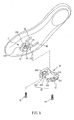
- the sole 90 is provided with a plurality of slots 91, 92 and 93.
- the sole 90 is provided with a plurality of slots 91, 92 and 93.
- a positioning aid 101 shaped to mate a cleat 100' is provided as an aim for alignment of the cleat 100', as the concept disclosed in US Patent 7,219,451 .
- the positioning aid 101 includes a feature to ensure that the cleat 100' is assembled thereto in only one orientation. Thereby, in the course of replacing the cleat 100', the undetached positioning aid 101 helps to pose the cleat 100' in position, so that after the cleat 100' and the positioning aid 101 are put together, and the cleat 100' is fastened to the sole 90 by means of a screw, it is ensured that the new cleat 100' is placed right on the position where the old cleat 100' was positioned.
- this solution depends on the additional positioning aid 101, which needs additional costs for making molds, forming and assembling the additional part, thus being imperfect.
- the invention provides a replaceable bicycle shoe cleat assembly according to claim 1. Further embodiments of the invention are described in the dependent claims.
- a primary objective of the present invention is to provide a cleat assembly which allows selective replacement of only a part that has been worn and unusable, thereby facilitating saving resources and reducing costs for purchasing spares.
- Another objective of the present invention is to provide a cleat assembly that can be accurately positioned without the need for any additional positioning aid as used in the prior-art solution, so as to save additional costs for making molds, forming and assembling the additional part, thereby improving competitiveness.
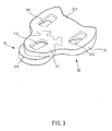
- the present invention provides a replaceable bicycle shoe cleat assembly. Referring to Figures 3 to 4 , it has a first cleat member 10 and a second cleat member 20.
- the first cleat member 10 has a first fastening portion 11, a first positioning portion 13, and at least one first through hole 111 formed therebetween.
- the first through hole 111 allows a screw 15 to pass therethrough and then engage with a slot 91 formed on a shoe sole 90 (referring to Figure 5 ), so as to fasten the first cleat member 10 to the shoe sole 90.
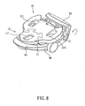
- the first fastening portion 11 has a front end, namely the end opposite to the first positioning portion 13, formed with a front engaging edge 113 for engaging a front clamping member 81 of a clipless pedal 80 (referring to Figure 8 ).
- the second cleat member 20 has a second fastening portion 21 and a second positioning portion 23 for mating the first positioning portion 13.
- the second fastening portion 21 includes at least one second through hole 211 and at least one third through hole 213.
- the second through hole 211 and the third through hole 213 allow screws 25, 27 to pass therethrough and then engage with two other slots 92, 93 formed on the shoe sole 90, so as to fasten the second cleat member 20 to the sole 90.
- the second fastening portion 21 has its rear end, namely the end opposite to the second positioning portion 23, formed with a rear engaging edge 215 for engaging a rear clamping member 82 of the clipless pedal 80 (referring to Figure 8 ).
- the first positioning portion 13 of the first cleat member 10 and the second positioning portion 23 of the second cleat member 20 are configured to couple with each other only in one orientation, and when any of the mated first cleat member 10 and second cleat member 20 receives a horizontal driving force, the driving force can be transmitted to the other thereof.
- the first cleat member 10 and the second cleat member 20 are fastened by the screws 15, 25 and 27 screwed into the slots 91, 92 and 93 of the shoe sole 90, the first cleat member 10 and the second cleat member 20 are vertically positioned by the shoe sole 90 and the screws 15, 25 and 27, and are horizontally driven by each other. Thereby, the first cleat member 10 and the second cleat member 20, as a whole cleat assembly, are positioned in all directions with respect to the shoe sole 90.
- the second cleat member 20 can be independently replaced while the first cleat member 10 is remained for further use. This is favorable for saving resources and reducing costs for purchasing spares.
- the screws 25, 27 are first unscrewed from the second through hole 211 and the third through hole 213, and then the second cleat member 20 can be separated from the shoe sole 90.
- the new second cleat member 20 is such placed that the second positioning portion 23 thereof mates the first positioning portion 13 of the first cleat member 10. Since the first positioning portion 13 of the first cleat member 10 and the second positioning portion 23 of the second cleat member 20 are designed to be coupled with each other in the only orientation, the newly installed second cleat member 20 can be properly posed basing on the unmoved first cleat member 10, and thus reach a position identical to that of the old second cleat member 20 on the shoe sole 90.
- the screw 15 is first unscrew from the first through hole 111, and then the worn first cleat member 10 is taken apart from the sole 90. Afterward, the new first cleat member 10 is such posed that the first positioning portion 13 mates the second positioning portion 23 of the second cleat member 20. Since the first positioning portion 13 of the first cleat member 10 and the second positioning portion 23 of the second cleat member 20 are designed to be coupled with each other in the only orientation, the newly installed first cleat member 10 can be properly posed basing on the unmoved second cleat member 20, and thus reach a position identical to that of the old first cleat member 10 on the shoe sole 90, as shown in Figure 6 .
- the disclosed structural feature ensures the first positioning portion 13 of the first cleat member 10 and the second positioning portion 23 of the second cleat member 20 to be mated in only one posture and to position each other, so that the replaced cleat member 10 or 20 can be correctly posed and positioned without the assistance from the positioning aid used in the prior art.
- the present invention helps to save additional costs for making molds, forming and assembling the additional part, thereby improving competitiveness.
- Figures 3 through 4 are referred to illustrate one embodiment of the present invention.
- configurations of the first cleat member 10 and the second cleat member 20 are discussed to show how the first positioning portion 13 and the second positioning portion 23 are mated and put together in only one orientation, and when any of the combined first and second cleat members 10, 20 receives a horizontal driving force, the horizontal driving force is transmitted to the other.
- the first positioning portion 13 of the first cleat member 10 is in a W-like shape bilaterally formed with paired arms 131.
- Each of the arms 131 is terminated with an anchor 133 extending in a direction perpendicular to an axis of the arm 131.
- the first positioning portion 13 is centrally formed with a promontory 135 between the two arms 131.
- the second positioning portion 23 is shaped as a recessed portion for fittingly receiving the first positioning portion 13.
- the second positioning portion 23 has arm recesses 231 for fittingly receiving the arms 131, anchor recesses 233 for fittingly receiving the terminal anchors 133 of the arms 131, and a promontory recess 235 for receiving the promontory 135.
- the first positioning portion 13 and the second positioning portion 23 can be only mated in a single posture.
- a user may horizontally swing his/her thenar in a shoe above the shoe sole 90 against a joint between the front end of the first fastening portion 11 of the first cleat member 10 and the front clamping member 81 of the clipless pedal 80, so as to depart the rear end of the second fastening portion 21 of the second cleat member 20 from the spring-controlled rear clamping member 82 of the clipless pedal 80.
- the arms 131 and the anchors 133 of the first cleat member 10 jointly act as a pushing force to transmit the swing force to a pushed force composed of the arm recesses 231 and anchor recesses 233 of the second cleat member 20. Since the force is transmitted between the first cleat member 10 and the second cleat member 20 in an inter-surface manner, the first positioning portion 13 and the second positioning portion 23 are unlikely to break or deform under stress acts thereon.
- first positioning portion of the first cleat member 10 and the second positioning portion of the second cleat member 20 may be shaped into a pair of noncircular mortise and tenon, such as a pair of tightly mating rectangular tenon 137 and mortise 237 as shown in Figure 7 .
- the cleat members 10, 20 can also be limited to mate each other in only one orientation and can drive each other horizontally.
- the rear engaging edge 215 of the second fastening portion 21 for engaging the rear clamping member 82 of the clipless pedal 80 may have a width W1 greater than a width of the rear clamping member 82, so that when the rear engaging edge of the second cleat member 20 is coupled with the rear clamping member 82 of the clipless pedal 80, the user is allowed to slightly swing his/her thenar on the clipless pedal 80 to finely adjust his/her pedaling posture, so as to improve pedaling comfortableness.
- the width W2 of the rear engaging edge of the second fastening portion may be sized to tightly fit the rear clamping member 82, so as to ensure firm combination therebetween for enhancing the cyclist's safety in riding.
Landscapes
- Health & Medical Sciences (AREA)
- General Health & Medical Sciences (AREA)
- Physical Education & Sports Medicine (AREA)
- Footwear And Its Accessory, Manufacturing Method And Apparatuses (AREA)
- Motorcycle And Bicycle Frame (AREA)
Applications Claiming Priority (1)
| Application Number | Priority Date | Filing Date | Title |
|---|---|---|---|
| TW099129551A TWI461156B (zh) | 2010-09-01 | 2010-09-01 | 可更換式自行車鞋扣片結構 |
Publications (3)
| Publication Number | Publication Date |
|---|---|
| EP2425732A2 EP2425732A2 (en) | 2012-03-07 |
| EP2425732A3 EP2425732A3 (en) | 2013-01-16 |
| EP2425732B1 true EP2425732B1 (en) | 2014-12-03 |
Family
ID=45350371
Family Applications (1)
| Application Number | Title | Priority Date | Filing Date |
|---|---|---|---|
| EP10197284.2A Active EP2425732B1 (en) | 2010-09-01 | 2010-12-29 | Replaceable bicycle shoe cleat assembly |
Country Status (3)
| Country | Link |
|---|---|
| US (1) | US20120047772A1 (zh) |
| EP (1) | EP2425732B1 (zh) |
| TW (1) | TWI461156B (zh) |
Families Citing this family (8)
| Publication number | Priority date | Publication date | Assignee | Title |
|---|---|---|---|---|
| US9826794B2 (en) | 2008-12-12 | 2017-11-28 | Speedplay, Inc. | Shoe sole mounting standard for bicycle cleat |
| GB2497533B (en) * | 2011-12-12 | 2013-11-27 | Double Life Cleat Ltd | Cleat for cycling shoes |
| GB201217555D0 (en) * | 2012-10-01 | 2012-11-14 | Coderre Andre | Ergonomic adjustment system for a clip-less bicycle pedal |
| FR3016153B1 (fr) * | 2014-01-09 | 2017-06-23 | Look Cycle Int | Ensemble compose d'une chaussure et d'une plaque de retenue de la chaussure sur une pedale automatique de cycle, plaque de retenue pour un tel ensemble, et chaussure pour celui-ci |
| JP6006760B2 (ja) * | 2014-04-22 | 2016-10-12 | 株式会社シマノ | 自転車用ペダル、クリート、および自転車用ペダルシステム |
| WO2016016738A1 (en) | 2014-07-31 | 2016-02-04 | Gabusi Francesco | Cycling shoe and related quick fit / release anchoring device |
| US11142282B2 (en) * | 2019-11-28 | 2021-10-12 | Cyclingdeal Usa, Inc. | Bicycle shoe cleat for clipless pedals |
| US11793277B2 (en) * | 2021-10-15 | 2023-10-24 | Shimano Inc. | Cleat adapter assembly for cycling shoe |
Family Cites Families (16)
| Publication number | Priority date | Publication date | Assignee | Title |
|---|---|---|---|---|
| WO1987007119A1 (en) * | 1986-05-27 | 1987-12-03 | Feldstein Frank I | Retractable bicycle shoe cleat |
| IT210729Z2 (it) * | 1987-05-28 | 1989-01-11 | Rapisarda Antonio | Dispositivo per intercollegare un pedale di bicicletta ed una scarpa da ciclista |
| US5079968A (en) * | 1990-04-18 | 1992-01-14 | Starner Alan L | Rotating bicycle shoe cleat |
| US5199192A (en) * | 1990-06-14 | 1993-04-06 | Nike, Inc. | Cycling shoe and outsole with rotatable cleat |
| US5657558A (en) * | 1991-08-14 | 1997-08-19 | Pohu; Georges | Assembly system on a sole, of an equipment linked to the use of a shoe |
| US5381708A (en) * | 1993-09-10 | 1995-01-17 | Liao; Wan M. | Pedal assembly for a bicycle |
| US5685093A (en) * | 1996-03-29 | 1997-11-11 | Lin; Wen-Hwa | Bicycle shoe |
| US6708584B2 (en) * | 2001-09-18 | 2004-03-23 | Shimano, Inc. | Bicycle pedal assembly |
| US6694846B2 (en) * | 2002-02-28 | 2004-02-24 | Shimano Inc. | Bicycle pedal |
| FR2858184B1 (fr) * | 2003-07-30 | 2005-10-21 | Look Cycle Int | Chaussure de cycliste a cale de retenue de la chaussure sur une pedale a fixation automatique |
| US20050210712A1 (en) * | 2004-03-26 | 2005-09-29 | Jau Guo J | Shoe attachment assembly for various cycles |
| US7178272B2 (en) * | 2004-07-22 | 2007-02-20 | Jin-Long Xie | Snap block structure for bicycle-use shoes |
| TWM264211U (en) * | 2004-10-15 | 2005-05-11 | Guo-Jr Jau | Structure improvement for bicycle pedal, pedal retention board, protective cap, and shoe sole retention nut holder |
| ITPD20050072A1 (it) * | 2005-03-11 | 2006-09-12 | Sidi Sport Srl | Calzatura ciclistica multi funzione |
| FR2919578B1 (fr) * | 2007-08-01 | 2009-09-18 | Look Cycle Internat Sa | "pedale automatique de cycle a ressort a lame" |
| US20130047464A1 (en) * | 2011-08-24 | 2013-02-28 | Tara Shuler | Toe traction device |
-
2010
- 2010-09-01 TW TW099129551A patent/TWI461156B/zh active
- 2010-12-16 US US12/969,879 patent/US20120047772A1/en not_active Abandoned
- 2010-12-29 EP EP10197284.2A patent/EP2425732B1/en active Active
Also Published As
| Publication number | Publication date |
|---|---|
| US20120047772A1 (en) | 2012-03-01 |
| TWI461156B (zh) | 2014-11-21 |
| EP2425732A3 (en) | 2013-01-16 |
| EP2425732A2 (en) | 2012-03-07 |
| TW201210522A (en) | 2012-03-16 |
Similar Documents
| Publication | Publication Date | Title |
|---|---|---|
| EP2425732B1 (en) | Replaceable bicycle shoe cleat assembly | |
| EP3150475B1 (en) | Electric bicycle frame | |
| US7866002B2 (en) | Combinative handlebar grip for bicycles or the like | |
| US9254016B2 (en) | Device for adapting a shoe to attach a cycling cleat | |
| US20120187648A1 (en) | Skateboard | |
| EP1602570A1 (en) | Releasably locking device for a bicycle component | |
| EP2369950B1 (en) | Shoe sole mounting standard for bicycle cleat | |
| US8763746B2 (en) | Mounting structure of handle switch device | |
| US11572129B2 (en) | Cleat assembly for clipless bicycle pedal | |
| US7322051B1 (en) | Fastening structure for headband of ski goggles | |
| US20110048167A1 (en) | Shoe positioning device of a bicycle | |
| US20120017471A1 (en) | Shoe accessory for cycling | |
| EP3019756B1 (en) | Structural assembly and method of assembly thereof | |
| KR100877555B1 (ko) | 보행자세 교정용 스프링 신발 | |
| US20120167711A1 (en) | Clipless Pedal | |
| CN106392967A (zh) | 棘轮扳手及其棘轮扳手头 | |
| US6520048B2 (en) | Bicycle pedal assembly provided with front side stop elements for preventing lateral movement of a cleat | |
| TWM505434U (zh) | 水壺結構 | |
| US9211933B2 (en) | Steering shaft modifier | |
| US20150078817A1 (en) | Coupling structure for resin parts, and method of manufacturing same | |
| US9737763B2 (en) | Swim fin | |
| CN112407132B (zh) | 一种高安全性的自行车踏板系统 | |
| USRE48786E1 (en) | Steering shaft modifier | |
| CN212797208U (zh) | 一种多功能的踏板结构 | |
| US20160075395A1 (en) | Steering shaft modifier |
Legal Events
| Date | Code | Title | Description |
|---|---|---|---|
| AK | Designated contracting states |
Kind code of ref document: A2 Designated state(s): AL AT BE BG CH CY CZ DE DK EE ES FI FR GB GR HR HU IE IS IT LI LT LU LV MC MK MT NL NO PL PT RO RS SE SI SK SM TR |
|
| AX | Request for extension of the european patent |
Extension state: BA ME |
|
| PUAI | Public reference made under article 153(3) epc to a published international application that has entered the european phase |
Free format text: ORIGINAL CODE: 0009012 |
|
| PUAL | Search report despatched |
Free format text: ORIGINAL CODE: 0009013 |
|
| AK | Designated contracting states |
Kind code of ref document: A3 Designated state(s): AL AT BE BG CH CY CZ DE DK EE ES FI FR GB GR HR HU IE IS IT LI LT LU LV MC MK MT NL NO PL PT RO RS SE SI SK SM TR |
|
| AX | Request for extension of the european patent |
Extension state: BA ME |
|
| RIC1 | Information provided on ipc code assigned before grant |
Ipc: A43B 5/14 20060101AFI20121211BHEP |
|
| 17P | Request for examination filed |
Effective date: 20130716 |
|
| RBV | Designated contracting states (corrected) |
Designated state(s): AL AT BE BG CH CY CZ DE DK EE ES FI FR GB GR HR HU IE IS IT LI LT LU LV MC MK MT NL NO PL PT RO RS SE SI SK SM TR |
|
| GRAP | Despatch of communication of intention to grant a patent |
Free format text: ORIGINAL CODE: EPIDOSNIGR1 |
|
| INTG | Intention to grant announced |
Effective date: 20140630 |
|
| GRAS | Grant fee paid |
Free format text: ORIGINAL CODE: EPIDOSNIGR3 |
|
| GRAA | (expected) grant |
Free format text: ORIGINAL CODE: 0009210 |
|
| AK | Designated contracting states |
Kind code of ref document: B1 Designated state(s): AL AT BE BG CH CY CZ DE DK EE ES FI FR GB GR HR HU IE IS IT LI LT LU LV MC MK MT NL NO PL PT RO RS SE SI SK SM TR |
|
| RAP1 | Party data changed (applicant data changed or rights of an application transferred) |
Owner name: VP COMPONENTS CO., LTD. |
|
| REG | Reference to a national code |
Ref country code: GB Ref legal event code: FG4D |
|
| REG | Reference to a national code |
Ref country code: AT Ref legal event code: REF Ref document number: 698827 Country of ref document: AT Kind code of ref document: T Effective date: 20141215 Ref country code: CH Ref legal event code: EP |
|
| REG | Reference to a national code |
Ref country code: IE Ref legal event code: FG4D |
|
| REG | Reference to a national code |
Ref country code: DE Ref legal event code: R096 Ref document number: 602010020671 Country of ref document: DE Effective date: 20150115 |
|
| REG | Reference to a national code |
Ref country code: NL Ref legal event code: T3 |
|
| REG | Reference to a national code |
Ref country code: AT Ref legal event code: MK05 Ref document number: 698827 Country of ref document: AT Kind code of ref document: T Effective date: 20141203 |
|
| PG25 | Lapsed in a contracting state [announced via postgrant information from national office to epo] |
Ref country code: NO Free format text: LAPSE BECAUSE OF FAILURE TO SUBMIT A TRANSLATION OF THE DESCRIPTION OR TO PAY THE FEE WITHIN THE PRESCRIBED TIME-LIMIT Effective date: 20150303 Ref country code: FI Free format text: LAPSE BECAUSE OF FAILURE TO SUBMIT A TRANSLATION OF THE DESCRIPTION OR TO PAY THE FEE WITHIN THE PRESCRIBED TIME-LIMIT Effective date: 20141203 Ref country code: ES Free format text: LAPSE BECAUSE OF FAILURE TO SUBMIT A TRANSLATION OF THE DESCRIPTION OR TO PAY THE FEE WITHIN THE PRESCRIBED TIME-LIMIT Effective date: 20141203 Ref country code: LT Free format text: LAPSE BECAUSE OF FAILURE TO SUBMIT A TRANSLATION OF THE DESCRIPTION OR TO PAY THE FEE WITHIN THE PRESCRIBED TIME-LIMIT Effective date: 20141203 |
|
| REG | Reference to a national code |
Ref country code: LT Ref legal event code: MG4D |
|
| PG25 | Lapsed in a contracting state [announced via postgrant information from national office to epo] |
Ref country code: HR Free format text: LAPSE BECAUSE OF FAILURE TO SUBMIT A TRANSLATION OF THE DESCRIPTION OR TO PAY THE FEE WITHIN THE PRESCRIBED TIME-LIMIT Effective date: 20141203 Ref country code: CY Free format text: LAPSE BECAUSE OF FAILURE TO SUBMIT A TRANSLATION OF THE DESCRIPTION OR TO PAY THE FEE WITHIN THE PRESCRIBED TIME-LIMIT Effective date: 20141203 Ref country code: AT Free format text: LAPSE BECAUSE OF FAILURE TO SUBMIT A TRANSLATION OF THE DESCRIPTION OR TO PAY THE FEE WITHIN THE PRESCRIBED TIME-LIMIT Effective date: 20141203 Ref country code: SE Free format text: LAPSE BECAUSE OF FAILURE TO SUBMIT A TRANSLATION OF THE DESCRIPTION OR TO PAY THE FEE WITHIN THE PRESCRIBED TIME-LIMIT Effective date: 20141203 Ref country code: RS Free format text: LAPSE BECAUSE OF FAILURE TO SUBMIT A TRANSLATION OF THE DESCRIPTION OR TO PAY THE FEE WITHIN THE PRESCRIBED TIME-LIMIT Effective date: 20141203 Ref country code: GR Free format text: LAPSE BECAUSE OF FAILURE TO SUBMIT A TRANSLATION OF THE DESCRIPTION OR TO PAY THE FEE WITHIN THE PRESCRIBED TIME-LIMIT Effective date: 20150304 Ref country code: LV Free format text: LAPSE BECAUSE OF FAILURE TO SUBMIT A TRANSLATION OF THE DESCRIPTION OR TO PAY THE FEE WITHIN THE PRESCRIBED TIME-LIMIT Effective date: 20141203 |
|
| PG25 | Lapsed in a contracting state [announced via postgrant information from national office to epo] |
Ref country code: BE Free format text: LAPSE BECAUSE OF NON-PAYMENT OF DUE FEES Effective date: 20141231 |
|
| PG25 | Lapsed in a contracting state [announced via postgrant information from national office to epo] |
Ref country code: SK Free format text: LAPSE BECAUSE OF FAILURE TO SUBMIT A TRANSLATION OF THE DESCRIPTION OR TO PAY THE FEE WITHIN THE PRESCRIBED TIME-LIMIT Effective date: 20141203 Ref country code: EE Free format text: LAPSE BECAUSE OF FAILURE TO SUBMIT A TRANSLATION OF THE DESCRIPTION OR TO PAY THE FEE WITHIN THE PRESCRIBED TIME-LIMIT Effective date: 20141203 Ref country code: PT Free format text: LAPSE BECAUSE OF FAILURE TO SUBMIT A TRANSLATION OF THE DESCRIPTION OR TO PAY THE FEE WITHIN THE PRESCRIBED TIME-LIMIT Effective date: 20150403 Ref country code: RO Free format text: LAPSE BECAUSE OF FAILURE TO SUBMIT A TRANSLATION OF THE DESCRIPTION OR TO PAY THE FEE WITHIN THE PRESCRIBED TIME-LIMIT Effective date: 20141203 Ref country code: CZ Free format text: LAPSE BECAUSE OF FAILURE TO SUBMIT A TRANSLATION OF THE DESCRIPTION OR TO PAY THE FEE WITHIN THE PRESCRIBED TIME-LIMIT Effective date: 20141203 |
|
| REG | Reference to a national code |
Ref country code: CH Ref legal event code: PL |
|
| PG25 | Lapsed in a contracting state [announced via postgrant information from national office to epo] |
Ref country code: IS Free format text: LAPSE BECAUSE OF FAILURE TO SUBMIT A TRANSLATION OF THE DESCRIPTION OR TO PAY THE FEE WITHIN THE PRESCRIBED TIME-LIMIT Effective date: 20150403 Ref country code: PL Free format text: LAPSE BECAUSE OF FAILURE TO SUBMIT A TRANSLATION OF THE DESCRIPTION OR TO PAY THE FEE WITHIN THE PRESCRIBED TIME-LIMIT Effective date: 20141203 |
|
| REG | Reference to a national code |
Ref country code: DE Ref legal event code: R097 Ref document number: 602010020671 Country of ref document: DE |
|
| REG | Reference to a national code |
Ref country code: IE Ref legal event code: MM4A |
|
| PG25 | Lapsed in a contracting state [announced via postgrant information from national office to epo] |
Ref country code: MC Free format text: LAPSE BECAUSE OF FAILURE TO SUBMIT A TRANSLATION OF THE DESCRIPTION OR TO PAY THE FEE WITHIN THE PRESCRIBED TIME-LIMIT Effective date: 20141203 |
|
| PLBE | No opposition filed within time limit |
Free format text: ORIGINAL CODE: 0009261 |
|
| STAA | Information on the status of an ep patent application or granted ep patent |
Free format text: STATUS: NO OPPOSITION FILED WITHIN TIME LIMIT |
|
| PG25 | Lapsed in a contracting state [announced via postgrant information from national office to epo] |
Ref country code: LI Free format text: LAPSE BECAUSE OF NON-PAYMENT OF DUE FEES Effective date: 20141231 Ref country code: CH Free format text: LAPSE BECAUSE OF NON-PAYMENT OF DUE FEES Effective date: 20141231 Ref country code: DK Free format text: LAPSE BECAUSE OF FAILURE TO SUBMIT A TRANSLATION OF THE DESCRIPTION OR TO PAY THE FEE WITHIN THE PRESCRIBED TIME-LIMIT Effective date: 20141203 Ref country code: IE Free format text: LAPSE BECAUSE OF NON-PAYMENT OF DUE FEES Effective date: 20141229 |
|
| 26N | No opposition filed |
Effective date: 20150904 |
|
| REG | Reference to a national code |
Ref country code: FR Ref legal event code: PLFP Year of fee payment: 6 |
|
| PG25 | Lapsed in a contracting state [announced via postgrant information from national office to epo] |
Ref country code: SI Free format text: LAPSE BECAUSE OF FAILURE TO SUBMIT A TRANSLATION OF THE DESCRIPTION OR TO PAY THE FEE WITHIN THE PRESCRIBED TIME-LIMIT Effective date: 20141203 |
|
| PG25 | Lapsed in a contracting state [announced via postgrant information from national office to epo] |
Ref country code: SM Free format text: LAPSE BECAUSE OF FAILURE TO SUBMIT A TRANSLATION OF THE DESCRIPTION OR TO PAY THE FEE WITHIN THE PRESCRIBED TIME-LIMIT Effective date: 20141203 |
|
| PG25 | Lapsed in a contracting state [announced via postgrant information from national office to epo] |
Ref country code: BE Free format text: LAPSE BECAUSE OF FAILURE TO SUBMIT A TRANSLATION OF THE DESCRIPTION OR TO PAY THE FEE WITHIN THE PRESCRIBED TIME-LIMIT Effective date: 20141203 |
|
| PG25 | Lapsed in a contracting state [announced via postgrant information from national office to epo] |
Ref country code: BG Free format text: LAPSE BECAUSE OF FAILURE TO SUBMIT A TRANSLATION OF THE DESCRIPTION OR TO PAY THE FEE WITHIN THE PRESCRIBED TIME-LIMIT Effective date: 20141203 |
|
| PG25 | Lapsed in a contracting state [announced via postgrant information from national office to epo] |
Ref country code: TR Free format text: LAPSE BECAUSE OF FAILURE TO SUBMIT A TRANSLATION OF THE DESCRIPTION OR TO PAY THE FEE WITHIN THE PRESCRIBED TIME-LIMIT Effective date: 20141203 Ref country code: MT Free format text: LAPSE BECAUSE OF FAILURE TO SUBMIT A TRANSLATION OF THE DESCRIPTION OR TO PAY THE FEE WITHIN THE PRESCRIBED TIME-LIMIT Effective date: 20141203 Ref country code: LU Free format text: LAPSE BECAUSE OF NON-PAYMENT OF DUE FEES Effective date: 20141229 Ref country code: HU Free format text: LAPSE BECAUSE OF FAILURE TO SUBMIT A TRANSLATION OF THE DESCRIPTION OR TO PAY THE FEE WITHIN THE PRESCRIBED TIME-LIMIT; INVALID AB INITIO Effective date: 20101229 |
|
| REG | Reference to a national code |
Ref country code: FR Ref legal event code: PLFP Year of fee payment: 7 |
|
| REG | Reference to a national code |
Ref country code: FR Ref legal event code: PLFP Year of fee payment: 8 |
|
| PGFP | Annual fee paid to national office [announced via postgrant information from national office to epo] |
Ref country code: IT Payment date: 20171124 Year of fee payment: 8 |
|
| PG25 | Lapsed in a contracting state [announced via postgrant information from national office to epo] |
Ref country code: MK Free format text: LAPSE BECAUSE OF FAILURE TO SUBMIT A TRANSLATION OF THE DESCRIPTION OR TO PAY THE FEE WITHIN THE PRESCRIBED TIME-LIMIT Effective date: 20141203 |
|
| PG25 | Lapsed in a contracting state [announced via postgrant information from national office to epo] |
Ref country code: AL Free format text: LAPSE BECAUSE OF FAILURE TO SUBMIT A TRANSLATION OF THE DESCRIPTION OR TO PAY THE FEE WITHIN THE PRESCRIBED TIME-LIMIT Effective date: 20141203 |
|
| PG25 | Lapsed in a contracting state [announced via postgrant information from national office to epo] |
Ref country code: IT Free format text: LAPSE BECAUSE OF NON-PAYMENT OF DUE FEES Effective date: 20181229 |
|
| P01 | Opt-out of the competence of the unified patent court (upc) registered |
Effective date: 20230516 |
|
| PGFP | Annual fee paid to national office [announced via postgrant information from national office to epo] |
Ref country code: GB Payment date: 20231226 Year of fee payment: 14 |
|
| PGFP | Annual fee paid to national office [announced via postgrant information from national office to epo] |
Ref country code: NL Payment date: 20231213 Year of fee payment: 14 Ref country code: FR Payment date: 20231219 Year of fee payment: 14 Ref country code: DE Payment date: 20231204 Year of fee payment: 14 |