EP2425708A1 - Leistungsgerät zur betätigung von bewässerungsdrehpunkten - Google Patents
Leistungsgerät zur betätigung von bewässerungsdrehpunkten Download PDFInfo
- Publication number
- EP2425708A1 EP2425708A1 EP10769359A EP10769359A EP2425708A1 EP 2425708 A1 EP2425708 A1 EP 2425708A1 EP 10769359 A EP10769359 A EP 10769359A EP 10769359 A EP10769359 A EP 10769359A EP 2425708 A1 EP2425708 A1 EP 2425708A1
- Authority
- EP
- European Patent Office
- Prior art keywords
- irrigation
- turbine
- pressure
- energy
- pivot
- Prior art date
- Legal status (The legal status is an assumption and is not a legal conclusion. Google has not performed a legal analysis and makes no representation as to the accuracy of the status listed.)
- Withdrawn
Links
- 238000003973 irrigation Methods 0.000 title claims abstract description 44
- 230000002262 irrigation Effects 0.000 title claims abstract description 44
- XLYOFNOQVPJJNP-UHFFFAOYSA-N water Substances O XLYOFNOQVPJJNP-UHFFFAOYSA-N 0.000 claims abstract description 15
- 230000007246 mechanism Effects 0.000 claims abstract description 9
- 238000009825 accumulation Methods 0.000 claims abstract description 3
- 238000004519 manufacturing process Methods 0.000 claims abstract description 3
- 238000009826 distribution Methods 0.000 claims abstract 3
- 230000001105 regulatory effect Effects 0.000 claims description 3
- 239000003990 capacitor Substances 0.000 claims description 2
- 239000003638 chemical reducing agent Substances 0.000 claims description 2
- 238000001914 filtration Methods 0.000 claims description 2
- 238000005457 optimization Methods 0.000 claims description 2
- 230000009466 transformation Effects 0.000 claims 1
- 230000008901 benefit Effects 0.000 description 5
- 238000012423 maintenance Methods 0.000 description 5
- 238000009434 installation Methods 0.000 description 4
- 238000009530 blood pressure measurement Methods 0.000 description 3
- 230000009471 action Effects 0.000 description 2
- 238000010616 electrical installation Methods 0.000 description 2
- 238000005516 engineering process Methods 0.000 description 2
- 230000006978 adaptation Effects 0.000 description 1
- XAGFODPZIPBFFR-UHFFFAOYSA-N aluminium Chemical compound [Al] XAGFODPZIPBFFR-UHFFFAOYSA-N 0.000 description 1
- 229910052782 aluminium Inorganic materials 0.000 description 1
- 230000005540 biological transmission Effects 0.000 description 1
- 230000003139 buffering effect Effects 0.000 description 1
- 230000000295 complement effect Effects 0.000 description 1
- 230000001143 conditioned effect Effects 0.000 description 1
- 238000010276 construction Methods 0.000 description 1
- 230000003292 diminished effect Effects 0.000 description 1
- 239000003651 drinking water Substances 0.000 description 1
- 235000020188 drinking water Nutrition 0.000 description 1
- 230000008030 elimination Effects 0.000 description 1
- 238000003379 elimination reaction Methods 0.000 description 1
- 238000005265 energy consumption Methods 0.000 description 1
- 238000004146 energy storage Methods 0.000 description 1
- 230000002349 favourable effect Effects 0.000 description 1
- 238000003898 horticulture Methods 0.000 description 1
- 230000006872 improvement Effects 0.000 description 1
- 230000009467 reduction Effects 0.000 description 1
- 238000006467 substitution reaction Methods 0.000 description 1
Images

Classifications
-
- A—HUMAN NECESSITIES
- A01—AGRICULTURE; FORESTRY; ANIMAL HUSBANDRY; HUNTING; TRAPPING; FISHING
- A01G—HORTICULTURE; CULTIVATION OF VEGETABLES, FLOWERS, RICE, FRUIT, VINES, HOPS OR SEAWEED; FORESTRY; WATERING
- A01G25/00—Watering gardens, fields, sports grounds or the like
- A01G25/09—Watering arrangements making use of movable installations on wheels or the like
- A01G25/092—Watering arrangements making use of movable installations on wheels or the like movable around a pivot centre
-
- A—HUMAN NECESSITIES
- A01—AGRICULTURE; FORESTRY; ANIMAL HUSBANDRY; HUNTING; TRAPPING; FISHING
- A01G—HORTICULTURE; CULTIVATION OF VEGETABLES, FLOWERS, RICE, FRUIT, VINES, HOPS OR SEAWEED; FORESTRY; WATERING
- A01G25/00—Watering gardens, fields, sports grounds or the like
- A01G25/16—Control of watering
-
- H—ELECTRICITY
- H02—GENERATION; CONVERSION OR DISTRIBUTION OF ELECTRIC POWER
- H02K—DYNAMO-ELECTRIC MACHINES
- H02K7/00—Arrangements for handling mechanical energy structurally associated with dynamo-electric machines, e.g. structural association with mechanical driving motors or auxiliary dynamo-electric machines
- H02K7/18—Structural association of electric generators with mechanical driving motors, e.g. with turbines
- H02K7/1807—Rotary generators
- H02K7/1823—Rotary generators structurally associated with turbines or similar engines
Definitions
- the present invention refers to a power device for actuating irrigation pivots, whose evident end is that of constituting a means of electrical supply to the control system as well as to the movement of a pivot irrigation machine.
- the objective of the invention is to provide a device that takes advantage of the pressure differentials of a traditional irrigation system as opposed to an irrigation system with a "low consumption Pivot", in order to produce the electric energy necessary for the operation of the Pivot, which allows for the saving of energy in said systems of Pivot irrigation systems and at the same time allows for the possibility of eliminating the conventional electric installations and / or the diesel generators in substitution for them.
- Pivot irrigation is a technology developed after the first half of the 20 th century, widely used at a global level, fundamentally for the irrigation of horticulture crops, feeds, and extensive crops.
- the basic components of the Pivot irrigation system are: a system of pipes, a system of energy supply, PVC or aluminum piping with hydrants and an irrigation structure with pressure emitters and regulators, in which the energy supply systems employed currently are one of two types: One by connection to the existing electric network plus the connection with the electric cables to the central pivot. The other using a Diesel generating set system, although in this case there exist the inconveniences of maintenance, gasoil supply and the risk of theft.
- Central-pivot, lateral move, and hippodrome irrigation systems all exist. They are all composed of self-propelled structures equipped with sprinkler irrigation and control elements which make it possible to irrigate large surfaces with low installation and maintenance costs.
- the structures are formed by a series of tubes in the form of an arch, connected to an intake, elevated to 4 m in height and suspended in towers that are between 30 and 60 m apart. Supporting these towers are two wheels, which are propelled by an electric motor located in the axis of the tower.
- the central pivot irrigation system involves applying a controlled rain, as much in intensity as in uniformity, over the plot.
- the objective is that the water infiltrates in the same spot as it falls, being a continuous shift system while performing water application, 98% uniformity is achieved.
- the energy source necessary for the operation of the pivot irrigation system can be solved in two different ways.
- One way is through electric power supplied by the proximity to a power line.
- the other through a diesel generator situated in the "head" of the pivot.
- a pressure-reducing valve is placed in the plots, before delivery to the plot, creating a dissipated power in the energy jump to the pressure-reducing valve for its performance.
- the proposed device has been designed to solve the aforementioned problem; to obtain an alternate energy for the movement of the pivot, using, as a source of energy, the excess pressure that is dissipated from the pressure-reducing valves located in the different irrigation intakes in the network, taking advantage of two of the operational characteristics of the pivot which are; functioning with low pressure and less energy consumption for transfer.
- the energy necessities for the operation of the pivot with the device of the invention requires supply to two systems; one for the control system and the other for the transfer system to the towers.
- the device which utilizes part of the pressure lost to the pressure-reducing valve of the hydrant, or of the pressure regulators of the nozzles on the pivot, and constitutes, a part from a turbine with flow regulators and control of the energy produced at the entrance itself and connected logically to the corresponding irrigation intake, to the exit as well as to the entrance of said turbine, pressure controls, or analogous detectors of pressure have been planned.
- the regulation of the energy flow at the entrance of the turbine is done by an actuator mechanism, while the mechanical energy provided by the turbine generator is supplied to a specific mechanism.
- the mechanical energy produced by the turbine is supplied to an alternator through the corresponding mechanism, an alternator that generates a continuous current to supply the batteries with charging ability.
- the device also contains a single-phase inverter to transform the continuous current stored in the batteries into an alternate current, complementing the device with a frequency converter, which doubles the function of the single-phase current to a three-phase current while operating the buffering of the intensity peaks during the starting of the motors of the towers by start-up ramp accompanied by various supply connections to the tower transfer system, with a power transformer and with the power connections to the command and control box.
- a single-phase inverter to transform the continuous current stored in the batteries into an alternate current, complementing the device with a frequency converter, which doubles the function of the single-phase current to a three-phase current while operating the buffering of the intensity peaks during the starting of the motors of the towers by start-up ramp accompanied by various supply connections to the tower transfer system, with a power transformer and with the power connections to the command and control box.
- the power device of the invention uses the excess energy that is found in the irrigation intakes on the plot, due to the network of energy dimensions for the use of specific irrigation systems, which require a pressure between 20 and 50 m.c.a.
- the energy is created at the base of the plot, consuming between 10 and 20 m in pressure measurement allowing good operation of the pivot at precisely 20 to 25 m.c.a.
- the device of the invention it is possible to save the need for electric power supply by diesel generators or electrical infrastructure next to the location of the pivot, counteracting the historical advantages of the irrigation systems based on total coverage.
- the device of the invention makes the production of all energy demands of the pivot possible (power to the electric motors, power transfer and power to the command and control box), all with absolute reliability. Its operation is conditioned to the passing of water through the system, which uses the irrigation application and utilization of the pressure that would otherwise be lost to the pressure-reducing valve or nozzle pressure regulators. This pressure loss is transformed into electric energy and, moreover, diminishes the pressure on the network to an optimal working point for the pivot (2.5 atm).
- the device increases the versatility of irrigation pivots, adding a new differentiating feature and increasing its competitiveness, allowing for the elimination of diesel generators and / or electrical installations and achieving:
- the device contributes to the improvement of the environment, avoiding CO2 emissions to the atmosphere and avoiding the pollution that is caused by the manipulation of generators and construction of electrical infrastructure.
- the new field of action identified is for the drinking water supply networks, which share similar characteristics to the pressurized irrigation systems.
- the installations present various flow-pressure conditions, higher in some cases than those of irrigation networks, so they are highly proficient for the system's use.
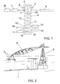
- the device of the invention is applicable to the corresponding irrigation supply (1) for the movement of a pivot, using the energy that is dissipated in the pressure-reducing valve (19) or in the pressure regulators of the nozzles of the pivot, including a turbine (2) with a flow regulating device at its entrance by means of an actuator mechanism (3) of the flow regulating device, controlled by two pressure manometers or similar detectors to control the passing of water through the turbine and the minimum pressure at the entrance of the pivot (4 & 5).
- the first of these is located at the entrance and the second is located at the exit where the turbine has a minimum exit pressure of 20-22 mca for the supply of (6) "a modified pivot of low pressure and low consumption in the transfer of itself", pivot that is turned with support from the wheels (7) around the tower or "head” (8) anchored to the ground.
- a transmission system which can be a set of pulleys and belts (9), an alternator (10) of continuous current, at 24 V and single-phase, whose alternator supplies the current to various energy accumulation batteries (11), which are connected to an inverter group (12) through which the continual energy at 24 V is transformed into alternate energy at 230 V, associated with the inverter group (12) is a transformer (13) from which is supplied the corresponding command and control box (14) of the pivot (6), while set apart from the inverter group (12) and through a frequency converter (15) supply is fed to the motors (16) of the towers of the pivot, with support from the wheels (7) for the movement of these and, therefore, of the pivot itself.
- a transmission system which can be a set of pulleys and belts (9), an alternator (10) of continuous current, at 24 V and single-phase, whose alternator supplies the current to various energy accumulation batteries (11), which are connected to an inverter group (12) through which the continual energy at 24 V is transformed into alternate energy at
- a continuation of the frequency inverter provides a filtration device (17) to reduce the noise of the electrical signal.
Landscapes
- Engineering & Computer Science (AREA)
- Water Supply & Treatment (AREA)
- Life Sciences & Earth Sciences (AREA)
- Environmental Sciences (AREA)
- Power Engineering (AREA)
- Other Liquid Machine Or Engine Such As Wave Power Use (AREA)
Applications Claiming Priority (2)
| Application Number | Priority Date | Filing Date | Title |
|---|---|---|---|
| ES200900823U ES1070248Y (es) | 2009-04-30 | 2009-04-30 | Dispositivo energetico para el accionamiento de pivots de riego |
| PCT/ES2010/000186 WO2010125213A1 (es) | 2009-04-30 | 2010-04-28 | Dispositivo energético para el accionamiento de pivots de riego |
Publications (2)
| Publication Number | Publication Date |
|---|---|
| EP2425708A1 true EP2425708A1 (de) | 2012-03-07 |
| EP2425708A4 EP2425708A4 (de) | 2015-08-19 |
Family
ID=40791733
Family Applications (1)
| Application Number | Title | Priority Date | Filing Date |
|---|---|---|---|
| EP10769359.0A Withdrawn EP2425708A4 (de) | 2009-04-30 | 2010-04-28 | Leistungsgerät zur betätigung von bewässerungsdrehpunkten |
Country Status (3)
| Country | Link |
|---|---|
| EP (1) | EP2425708A4 (de) |
| ES (1) | ES1070248Y (de) |
| WO (1) | WO2010125213A1 (de) |
Cited By (1)
| Publication number | Priority date | Publication date | Assignee | Title |
|---|---|---|---|---|
| FR3061408A1 (fr) * | 2017-01-04 | 2018-07-06 | 2 Gareni Ind | Dispositif d'irrigation autonome alimente par une source hydraulique |
Family Cites Families (9)
| Publication number | Priority date | Publication date | Assignee | Title |
|---|---|---|---|---|
| FR835094A (fr) * | 1938-03-11 | 1938-12-12 | Mode de propulsion pour appareils d'arrosage à déplacement automatique | |
| US3750001A (en) * | 1969-11-28 | 1973-07-31 | E Mccloskey | Remote, completely self-contained, self-maintaining power supply apparatus for powering a pressurized-liquid distributing and disseminating system |
| US3642204A (en) * | 1969-11-28 | 1972-02-15 | Edward W Mccloskey | Waterflow-controlling apparatus for an automatic irrigation system |
| FR2582475A1 (fr) * | 1985-06-03 | 1986-12-05 | Realisations Thermiques Et | Installation pour l'irrigation de terrains agricoles ou similaires |
| US4838310A (en) * | 1988-03-28 | 1989-06-13 | Motorola, Inc. | Hydroelectrically powered, remotely controlled irrigation system |
| US5333785A (en) * | 1991-12-19 | 1994-08-02 | Dodds Graeme C | Wireless irrigation system |
| US7349763B2 (en) * | 2004-10-30 | 2008-03-25 | Norman Ivans | System and method for systematically irrigating subregions of an irrigation region |
| AU2008350784A1 (en) * | 2008-02-14 | 2009-08-20 | Vinidex Pty Limited | Pivot irrigator drive system |
| GB2466654A (en) * | 2009-01-02 | 2010-07-07 | Anthony Barker | An aerator and mixer arrangement |
-
2009
- 2009-04-30 ES ES200900823U patent/ES1070248Y/es not_active Expired - Lifetime
-
2010
- 2010-04-28 EP EP10769359.0A patent/EP2425708A4/de not_active Withdrawn
- 2010-04-28 WO PCT/ES2010/000186 patent/WO2010125213A1/es not_active Ceased
Non-Patent Citations (1)
| Title |
|---|
| See references of WO2010125213A1 * |
Cited By (1)
| Publication number | Priority date | Publication date | Assignee | Title |
|---|---|---|---|---|
| FR3061408A1 (fr) * | 2017-01-04 | 2018-07-06 | 2 Gareni Ind | Dispositif d'irrigation autonome alimente par une source hydraulique |
Also Published As
| Publication number | Publication date |
|---|---|
| WO2010125213A1 (es) | 2010-11-04 |
| ES1070248Y (es) | 2010-03-31 |
| ES1070248U (es) | 2009-07-02 |
| EP2425708A4 (de) | 2015-08-19 |
Similar Documents
| Publication | Publication Date | Title |
|---|---|---|
| KR101809000B1 (ko) | 부체식 풍력 발전 장치의 메인터넌스 방법 | |
| US4918369A (en) | Hydro-energy conversion system | |
| RU2733063C1 (ru) | Способ управления электрической распределительной сетью | |
| CN103895823A (zh) | 潜浮聚能导向式波浪能发电平台 | |
| US11576313B2 (en) | System, method and apparatus for providing a solar pump system for use within a mechanized irrigation system | |
| EP2102492A1 (de) | Konzentrator für windturbine | |
| WO2011146348A4 (en) | River high pressure energy conversion machine | |
| CN111685016B (zh) | 山区斜坡茶园喷灌分级抽水变频节能方法 | |
| CN204860399U (zh) | 一种太阳能园林绿化喷洒装置 | |
| US20080238099A1 (en) | Water supply tunnel secondary purpose turbine electric power generator system | |
| US20160333844A1 (en) | Pumped-storage system | |
| EP2425708A1 (de) | Leistungsgerät zur betätigung von bewässerungsdrehpunkten | |
| CN201609684U (zh) | 大型行走式灌溉水田车 | |
| WO2014139457A1 (zh) | 海浪稳定发电系统 | |
| CN115443891B (zh) | 一种根据太阳辐照强度自动调节滴灌流量的方法及其装置 | |
| US20250043881A1 (en) | Micro-generation self-energized water transportation pipe adjustment valve device | |
| US20130113220A1 (en) | Fluid-driven power generation apparatus and system for generating electricity and method of assembling the fluid-driven power generation apparatus | |
| WO2014139459A1 (zh) | 风力稳定发电系统 | |
| CN109863982A (zh) | 一种太阳能经济型农业喷洒系统 | |
| US12490693B2 (en) | System, method and apparatus for providing a solar pump system for use within a mechanized irrigation system | |
| KR20060122432A (ko) | 풍력 발전기 | |
| CN108675402A (zh) | 风能海水淡化系统 | |
| CN221539632U (zh) | 一种水利管道对接装置 | |
| KR102566193B1 (ko) | 관로내 유체를 이용한 발전장치와 이를 이용한 무전원 IoT 기반 원격 수압 및 맨홀내 유해가스 상시 측정 시스템 | |
| JP4597257B1 (ja) | 水力発電システム |
Legal Events
| Date | Code | Title | Description |
|---|---|---|---|
| PUAI | Public reference made under article 153(3) epc to a published international application that has entered the european phase |
Free format text: ORIGINAL CODE: 0009012 |
|
| 17P | Request for examination filed |
Effective date: 20111130 |
|
| AK | Designated contracting states |
Kind code of ref document: A1 Designated state(s): AT BE BG CH CY CZ DE DK EE ES FI FR GB GR HR HU IE IS IT LI LT LU LV MC MK MT NL NO PL PT RO SE SI SK SM TR |
|
| DAX | Request for extension of the european patent (deleted) | ||
| RA4 | Supplementary search report drawn up and despatched (corrected) |
Effective date: 20150716 |
|
| RIC1 | Information provided on ipc code assigned before grant |
Ipc: A01G 25/09 20060101ALI20150710BHEP Ipc: A01G 25/16 20060101AFI20150710BHEP Ipc: A01G 25/00 20060101ALI20150710BHEP Ipc: H02K 7/18 20060101ALI20150710BHEP |
|
| STAA | Information on the status of an ep patent application or granted ep patent |
Free format text: STATUS: THE APPLICATION IS DEEMED TO BE WITHDRAWN |
|
| 18D | Application deemed to be withdrawn |
Effective date: 20160216 |