EP2425236B1 - Simultaneous differential thermal analysis system - Google Patents
Simultaneous differential thermal analysis system Download PDFInfo
- Publication number
- EP2425236B1 EP2425236B1 EP10770232.6A EP10770232A EP2425236B1 EP 2425236 B1 EP2425236 B1 EP 2425236B1 EP 10770232 A EP10770232 A EP 10770232A EP 2425236 B1 EP2425236 B1 EP 2425236B1
- Authority
- EP
- European Patent Office
- Prior art keywords
- balance
- horizontal
- members
- vertical member
- sample
- Prior art date
- Legal status (The legal status is an assumption and is not a legal conclusion. Google has not performed a legal analysis and makes no representation as to the accuracy of the status listed.)
- Not-in-force
Links
- 238000004455 differential thermal analysis Methods 0.000 title 1
- 239000002131 composite material Substances 0.000 claims description 30
- 239000000463 material Substances 0.000 claims description 27
- 229910052751 metal Inorganic materials 0.000 claims description 9
- 239000002184 metal Substances 0.000 claims description 9
- 230000001105 regulatory effect Effects 0.000 claims description 2
- 239000000523 sample Substances 0.000 description 73
- 238000005259 measurement Methods 0.000 description 35
- 239000004020 conductor Substances 0.000 description 17
- 238000005303 weighing Methods 0.000 description 14
- RYGMFSIKBFXOCR-UHFFFAOYSA-N Copper Chemical compound [Cu] RYGMFSIKBFXOCR-UHFFFAOYSA-N 0.000 description 11
- 229910052802 copper Inorganic materials 0.000 description 11
- 239000010949 copper Substances 0.000 description 11
- 230000007246 mechanism Effects 0.000 description 10
- 238000006073 displacement reaction Methods 0.000 description 9
- 230000008859 change Effects 0.000 description 7
- 230000008878 coupling Effects 0.000 description 6
- 238000010168 coupling process Methods 0.000 description 6
- 238000005859 coupling reaction Methods 0.000 description 6
- 230000009977 dual effect Effects 0.000 description 6
- 230000003071 parasitic effect Effects 0.000 description 6
- 238000010438 heat treatment Methods 0.000 description 5
- 239000012212 insulator Substances 0.000 description 4
- 238000010926 purge Methods 0.000 description 4
- 230000004044 response Effects 0.000 description 4
- 239000000919 ceramic Substances 0.000 description 3
- 239000010437 gem Substances 0.000 description 3
- 229910001751 gemstone Inorganic materials 0.000 description 3
- 239000000725 suspension Substances 0.000 description 3
- 238000004458 analytical method Methods 0.000 description 2
- 238000000429 assembly Methods 0.000 description 2
- 230000000712 assembly Effects 0.000 description 2
- 230000000694 effects Effects 0.000 description 2
- 239000012530 fluid Substances 0.000 description 2
- 239000011521 glass Substances 0.000 description 2
- 239000002241 glass-ceramic Substances 0.000 description 2
- 230000005226 mechanical processes and functions Effects 0.000 description 2
- 239000000203 mixture Substances 0.000 description 2
- 230000003287 optical effect Effects 0.000 description 2
- -1 oxygen-free copper) Chemical compound 0.000 description 2
- 239000000758 substrate Substances 0.000 description 2
- 230000004580 weight loss Effects 0.000 description 2
- 229910001260 Pt alloy Inorganic materials 0.000 description 1
- 230000009471 action Effects 0.000 description 1
- 229910052782 aluminium Inorganic materials 0.000 description 1
- XAGFODPZIPBFFR-UHFFFAOYSA-N aluminium Chemical compound [Al] XAGFODPZIPBFFR-UHFFFAOYSA-N 0.000 description 1
- 238000009529 body temperature measurement Methods 0.000 description 1
- 230000015556 catabolic process Effects 0.000 description 1
- 230000000295 complement effect Effects 0.000 description 1
- 238000004320 controlled atmosphere Methods 0.000 description 1
- 238000001816 cooling Methods 0.000 description 1
- 238000002425 crystallisation Methods 0.000 description 1
- 230000008025 crystallization Effects 0.000 description 1
- 238000000354 decomposition reaction Methods 0.000 description 1
- 238000006731 degradation reaction Methods 0.000 description 1
- 230000004069 differentiation Effects 0.000 description 1
- 238000011156 evaluation Methods 0.000 description 1
- 238000002474 experimental method Methods 0.000 description 1
- 230000006872 improvement Effects 0.000 description 1
- 238000009434 installation Methods 0.000 description 1
- 239000011810 insulating material Substances 0.000 description 1
- 238000002844 melting Methods 0.000 description 1
- 230000008018 melting Effects 0.000 description 1
- 239000007769 metal material Substances 0.000 description 1
- 150000002739 metals Chemical class 0.000 description 1
- 150000004767 nitrides Chemical class 0.000 description 1
- 239000011368 organic material Substances 0.000 description 1
- 150000003071 polychlorinated biphenyls Chemical class 0.000 description 1
- 229920000642 polymer Polymers 0.000 description 1
- 239000012925 reference material Substances 0.000 description 1
- 239000013074 reference sample Substances 0.000 description 1
- 238000005070 sampling Methods 0.000 description 1
- 230000035945 sensitivity Effects 0.000 description 1
- 229910052709 silver Inorganic materials 0.000 description 1
- 239000004332 silver Substances 0.000 description 1
- 238000005476 soldering Methods 0.000 description 1
- 230000003068 static effect Effects 0.000 description 1
- 238000002411 thermogravimetry Methods 0.000 description 1
- 230000007704 transition Effects 0.000 description 1
Images


Classifications
-
- G—PHYSICS
- G01—MEASURING; TESTING
- G01G—WEIGHING
- G01G21/00—Details of weighing apparatus
- G01G21/02—Arrangements of bearings
- G01G21/07—Arrangements of bearings of flexure-plate bearings
-
- G—PHYSICS
- G01—MEASURING; TESTING
- G01G—WEIGHING
- G01G21/00—Details of weighing apparatus
- G01G21/14—Beams
- G01G21/16—Beams of composite construction; Connections between different beams
-
- G—PHYSICS
- G01—MEASURING; TESTING
- G01G—WEIGHING
- G01G21/00—Details of weighing apparatus
- G01G21/22—Weigh pans or other weighing receptacles; Weighing platforms
-
- G—PHYSICS
- G01—MEASURING; TESTING
- G01N—INVESTIGATING OR ANALYSING MATERIALS BY DETERMINING THEIR CHEMICAL OR PHYSICAL PROPERTIES
- G01N5/00—Analysing materials by weighing, e.g. weighing small particles separated from a gas or liquid
- G01N5/04—Analysing materials by weighing, e.g. weighing small particles separated from a gas or liquid by removing a component, e.g. by evaporation, and weighing the remainder
-
- G—PHYSICS
- G01—MEASURING; TESTING
- G01G—WEIGHING
- G01G21/00—Details of weighing apparatus
- G01G21/23—Support or suspension of weighing platforms
Definitions
- the present invention is related to apparatus for measuring thermal properties of samples of materials.
- a simultaneous thermal or differential thermal analyzer comprises a combination of a thermogravimetric analyzer, TGA (also known as a thermobalance), and either a differential thermal analyzer (DTA) or a differential scanning calorimeter (DSC).
- TGA thermogravimetric analyzer
- DTA differential thermal analyzer
- DSC differential scanning calorimeter
- an SDT allows a user to measure both the heat flows (DSC or DTA) and weight changes (TGA) associated with transitions in a material as a function of temperature and time in a controlled atmosphere. Simultaneous measurement of these key material properties not only improves productivity but also simplifies interpretation of results.
- the complementary information obtained allows differentiation between endothermic and exothermic events which have no associated weight loss (e.g. melting and crystallization) and those which involve a weight loss (e.g. degradation).
- the combined evaluation also assures identical experimental and sampling conditions for both measurements, thereby eliminating those sources of uncertainty.
- Simultaneous DSC-TGA covers a wide temperature range from below ambient to above 1500°C, making it a powerful tool for studying a wide variety of materials including organic materials, notably polymers, and ceramics, metals, and other inorganics.
- the design of such an SDT instrument comprises a combination of an existing microbalance component with a DTA or DSC measuring component.
- a DTA or DSC measuring component typically, early SDT instruments were based on existing laboratory balances.
- microbalances in common use in SDT and TGA instruments, both of which employ the null balance principle, in which a restoring force is applied to the balance structure to maintain the balance in equilibrium.
- the restoring force which is proportional to the change in weight, is the measured quantity in each type of microbalance.
- the restoring force is applied electromagnetically as a response to a displacement of the balance structure, which is typically detected by optical means.
- a first type of balance is the dual arm meter movement balance, in which a d'Arsonval meter movement (also referred to herein as a "meter movement balance”) supports the balance beam and applies the restoring force as a torque.
- a d'Arsonval meter movement also referred to herein as a "meter movement balance” supports the balance beam and applies the restoring force as a torque.
- a displacement sensor near the TGA balance senses movement of the balance away from the equilibrium position and electric circuitry generates the current necessary to restore the balance to equilibrium.
- the second type of balance used in SDT and TGA instruments is the guided balance, in which the weighed mass is supported by a mechanism that constrains the movement of the weighed mass.
- the guided balance mechanism comprises a parallel four-bar linkage with elastic flexure pivots. This mechanism is termed a parallel guided balance.
- An electromagnetic actuator is used to apply a restoring force to the linkage, while a displacement sensor detects movement away from the equilibrium position and electric circuitry generates any current necessary to restore the balance to equilibrium.
- SDT and TGA instruments may be classified as horizontal or vertical instruments based on the orientation of the heating furnace and the relative position of the balance.
- the measurement of weight may be perturbed by thermal expansion of the structure that extends into the furnace, and by forces exerted by movement of gas in the furnace caused by the action of purging the furnace or by buoyancy induced flows, in addition to buoyancy forces resulting from gas density changes.
- the magnitude of these weighing errors depends upon the configuration of the SDT instrument. In a horizontal furnace, thermal expansion of the beams that extend into the furnace may cause large weighing errors, while a vertical furnace configuration is largely immune to these effects, because thermal expansion occurs parallel to the Earth's gravitational field.
- an SDT instrument combines a TGA measurement with a DTA or DSC type measurement, which requires that at least the sample side of the heat flow rate sensing device be supported by the balance mechanism.
- a sample can be heated or cooled to examine changes in the sample induced by changes in temperature.
- the heating takes place while at least a portion of the member supporting the sample extends into a furnace used to heat the sample.
- mass changes in the sample cause the balance mechanism to deflect from equilibrium, such that the restoring force needed to maintain the equilibrium can be measured.
- a thermal signal (either DTA or DSC) is transmitted using wires that extend from the sample region to the stationary or fixed part of the instrument, so that analysis of the material changes taking place can be performed based upon the thermal signals received from the sample.
- the wires that carry the DSC or DTA signals from the sample region must connect the moving part of the balance to the fixed part.
- These signal wires typically exert a parasitic force on the balance that constitutes a weighing error.
- the wires contribute to weighing errors in SDT measurements.
- the forces exerted by the wires on the balance need not result in weighing errors, as long as the response in the wires to a displacement is linearly elastic.
- the forces the wires exert are strictly linearly proportional to the displacement of the wires and the proportionality constant does not change, weighing errors caused by the wires could be avoided.
- the response of the wires is not linearly elastic, weighing errors will result. Because the wires are usually deformed during installation in the SDT apparatus, the wires will almost always exert some force on the balance regardless of the balance position or whether any motion is taking place.
- the wires may relax over time, resulting in changes in the force exerted by the wires.
- the wires are bent to the required shape when they are installed in the SDT apparatus, such that the deformation of the wires is at least partially plastic in nature. Over time, some of the plastic strain relaxes, thus changing the force exerted by the wire in a static position, as well as the force resulting from a displacement of the balance.
- the wires can be annealed or stress relieved, but given that they are generally fine and easily bent, it is difficult to handle and install the wires without deforming them.
- pivot structures that are necessary to connect fixed parts of a balance to moving parts of the balance, or that connect two moving parts of a balance, can introduce forces that may influence the measurement of sample weight.
- the meter movement type is more sensitive and has faster dynamic response.
- the guided balance is more robust and is immune to the thermal expansion effects described above when used in a horizontal configuration.
- the guided balance-type SDT instrument may be used in conjunction with either the vertical or horizontal furnace configuration.
- the meter movement balance is used with the horizontal furnace configuration.
- the meter movement balance is typically employed in a differential weighing configuration in which two balances, a sample and a reference balance, are operated in parallel.
- One balance weighs the sample and its container, while the other balance weighs an empty container or an inert reference sample in the container.
- Subtracting the reference weight measurement from the sample weight measurement eliminates the weighing error due to thermal expansion of the weighing structure and the weighing error due to buoyancy forces acting on the apparatus.
- Sample buoyancy forces are still a potential source of error in the dual balance configuration. Since the dual balance configuration employs a horizontal furnace configuration, the balances are isolated from forces arising from fluid motion, whether due to purge gas flow or to buoyancy differences resulting from temperature variations in the furnace, because these forces act orthogonally to the gravitational field.
- each of the sample and reference balances includes a meter movement component, optical displacement sensor and electronics to maintain the respective balance in the equilibrium position.
- a dual balance SDT system suffers from potential mismatches between the components of the two balance assemblies, such as in the meter movements.
- Another shortcoming of this design is that the meter movement components (or “meter movements") must support the entire weight of the balance beam and DTA or DSC holder structure.
- D'Arsonval meter movements may be made with either jewel bearings or a thin taut band supporting the rotating part of the meter.
- taut band suspensions are preferred because they operate without friction. Displacement of the moving part of the meter twists the taut band slightly. Elastic deflection of the taut band is very linear and highly repeatable, whereas friction in jewel bearings is far more nonlinear and far less repeatable.
- jewel bearing meter movements can support much larger loads than those supported by taut band suspensions.
- the weighing capacity is limited to a small fraction of the capacity of the taut band, most of which is used to support the beam, holder, and sensor.
- the taut band instruments tend to have low weighing capacity.
- an improved SDT configuration includes a parallel guided balance structure that contains one or more members constructed from insulating material such as printed circuit board material (PCB).
- the PCB members are configured both to act as structural components of the balance and to conduct a sensor signal from a sample or reference temperature sensor used in a DTA or DSC measurement.
- an SDT balance comprises a plurality of PCB members that act as structural components and include conductors that run along the surface of the structural components and/or within the structural components so as to conduct electrical signals from sensor elements located in sample and reference holders.
- a continuous conductive path is formed that leads from a first PCB member to a second, adjacent PCB member, wherein the first and the second PCB member are mutually connected by a conductive flexure pivot.
- one or more pivots of the PCB-based SDT apparatus are configured using a crossed-flexure design, and are constructed so that the crossed flexures can carry the DTA or DSC signals between components of the balance structure.
- the cross flexures serve two separate functions: they provide 1) a conductive link between adjacent PCB members or between a PCB member and another structural member of the SDT apparatus, and 2) a pivoting means that allows the adjacent PCB members or PCB member and other structural member to pivot about one another.
- a crossed-flexure pivot comprises a crossed pair of electrically conductive flexible members and an abutment structure.
- the abutment structure comprises two pairs of abutments wherein a first pair of abutments is configured to attach to respective ends of a first flexible member and a second pair of abutments is configured to attach to respective ends of a second flexible member that crosses the first flexible member.
- the crossed-flexure pivots can be soldered directly to conductive traces on the printed circuit board material.
- a continuous electrical path is formed between conductors on a first PCB and conductors on an adjacent PCB.
- the continuous electrical path runs from the conductor on the first PCB through a first abutment affixed to the first PCB, through a first cross-flexure member attached in a first region to the first abutment, through a second abutment attached to the crossed-flexure member in a second region, and into a second conductor connected to the second abutment on an adjacent PCB.
- the crossed-flexure pivots are mechanically fastened to conductive traces on the printed circuit board material.
- a continuous electrical path is formed between conductors on a first PCB and conductors on an adjacent PCB.
- the continuous electrical path runs from the conductor on the first PCB through a first abutment affixed to the first PCB, through a first cross-flexure member attached in a first region to the first abutment, through a second abutment attached to the crossed-flexure member in a second region, and into a second conductor connected to the second abutment on an adjacent PCB.
- the abutment structure of a cross-flexure pivot in an SDT apparatus comprises a conductive sheet material such as sheet metal, including copper (e.g ., oxygen-free copper) or other metal.
- an abutment comprises a generally L-shaped structure in which a first leg of the "L” is affixed to a surface of a structural member, such as a PCB, and a second leg of the "L” extends outwardly from the surface of the structural member.
- the second leg of the "L" of an abutment is folded on itself so as to form a slot region that accommodates an end portion of a flat flexible member.
- the pair of flat flexible members forms a substantially orthogonal cross when the SDT apparatus is in an equilibrium position for weighing.
- Each flat flexible member may comprise a thin planar conductive strip in which the plane of the strip is substantially orthogonal to the plane of the PCB member.
- the abutments comprise a sheet metal material, such as copper (e.g ., oxygen-free copper), that is configured for easy soldering to conductive traces located on the PCB.
- a sheet metal material such as copper (e.g ., oxygen-free copper)
- an SDT instrument comprises a PCB/cross flexure pivot design in which adjacent structural members comprise two different PCB members or a PCB member and a non-PCB member that are electrically and mechanically coupled using a cross-flexure pivot.
- the SDT instrument comprises a parallel guided balance.
- the balance structure is housed in an enclosure that is maintained at a constant uniform temperature.
- the beams used to support the sample holders attach to the balance structure within the constant temperature enclosure.
- a parallel guided balance SDT apparatus comprises a four-bar parallel linkage that supports and guides a single structural member that supports sample and reference holders and associated DTA or DSC sensors.
- the linkage comprises a fixed vertical member that is joined to two equal length horizontal members by a first set of crossed flexure pivots, wherein the cross-flexure pivots are capable of transmitting DTA or DSC sensor signals between the fixed vertical member and horizontal members.
- a second vertical member of equal length to the fixed vertical member is joined to the opposite ends of the horizontal members by a second set of crossed flexure pivots.
- the second vertical member is thus constrained to move such that the second vertical member remains oriented parallel to the fixed member and in approximately a straight line as long as the displacements are small and the horizontal members remain close to the horizontal position.
- a component is provided to support the DTA or DSC sensor and sample and reference holders, wherein the component is attached to the movable member.
- at least the two horizontal members of the linkage are constructed of PCB material to which the first and second set of crossed-flexure pivots are attached, enabling the DSC or DTA signals to be carried from the moving portion of the balance to the fixed part of the balance without the need for flexible temperature sensor lead wires, thus avoiding the parasitic forces associated with such lead wires.
- a parallel-guided balance having a first and second set of cross-flexure pivots that join a horizontal member to a fixed vertical member and movable vertical member, respectively, is adapted for use with a vertical furnace or a horizontal furnace configuration.
- the present invention provides novel and inventive arrangements of components that can be used in apparatus that combine simultaneous gravimetric measurements of a sample with measurements of the sample that require propagation of electrical signals from the sample area to an apparatus for recording the electrical signals.
- embodiments of the present invention provide improved configurations of sample measurement balances that can be used in conjunction with thermal measurements in an SDT instrument.
- SDT instruments perform simultaneous gravimetric measurements and thermal measurements, such as DSC or DTA.
- An SDT apparatus can simultaneously measure changes in a plurality of sample properties that take place during heating, such as changes in weight, phase changes, and the like.
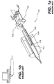
- FIGS 1a and 1b depict a known configuration of a measurement apparatus portion 100 of an SDT apparatus, in this case, a meter movement balance SDT.
- Apparatus 100 includes hardware for performing simultaneous thermal measurements (e.g ., DSC or DTA) and gravimetric measurements of a sample placed in sample holder 112.
- thermal measurements refers to measurements that use a thermocouple or other temperature-measuring device that is located at or near a sample or a reference holder.
- the thermal measurements can be, for example, measurements for sensing heat flow rate, as in known DSC/DTA sensors.
- a hallmark of the thermal measurements is that an electrical signal propagates along conductors leading from the sample area and is detected and analyzed by components (not shown) that are external to measurement apparatus 100.
- Apparatus 100 includes a differential horizontal balance that contains two meter movements 106 and accompanying sensors that are used to separately weigh samples and references placed in the sample and reference holders of respective sample and reference balance arms 108. Electrical signals are conducted from each thermocouple using wires that run from the sample or reference to an external point for detecting the electrical signals.
- the electrical wires can exert a force on the balance arms that can interfere with accurate measurement of weight changes taking place in the sample. For example, a set of wires coupled to the sample holder may exert a different force on the sample balance arm than that exerted on the reference balance arm by wires coupled to the reference holder.
- a balance assembly includes one or more composite structural members (also termed "composite members" herein, which refers to the fact that the members may have an insulating part and a conductive part) that include an insulating portion and conductive portions, for example, conductive paths that are configured to conduct electrical signals from a sample or reference sensor.
- the structural members thus perform a mechanical function and may also perform an electrical function.
- the structural members can be fabricated from printed circuit board material (PCB) or similar material, or another type of insulator material, such as glass, glass ceramic, or other material.
- a conductive material is disposed on and/or within the insulator.
- the conductive material can be plated metal, deposited metal, or similar known conductors that are used in printed circuit boards, for example.
- the composite member is used as a horizontal member of an SDT balance, such as a horizontal member of a parallel guided balance.
- conductive paths disposed within and/or upon the surface of a composite member are used in place of wires to conduct electrical signals from sample and reference sensors.
- the composite members are configured to mechanically couple with the rest of a balance assembly so as to reduce any parasitic force acting on the balance in comparison to known SDT balances in which wires are used to transmit signals between adjacent components where a relative motion takes place between components.
- the mechanical coupling of a composite member to an adjacent member is facilitated using a pivot, such as a crossed-flexure pivot.
- the pivot is formed from a conductive material, such as a sheet metal and is configured to electrically couple conductive paths disposed on the composite member with conductors disposed in the adjacent component so as to form a continuous electrical path between the adjacent components that is not interrupted when the adjacent components are pivoted with respect to one another.
- FIG. 2 depicts a coupling assembly 200 of a balance in which a cross-flexure pivot is configured to mechanically and electrically couple adjacent composite members, in accordance with an embodiment of the present invention.
- the adjacent composite members 202 can be, for example, an insulating substrate that is provided with conductive paths (also termed "traces" herein) on its surface and/or within the substrate.
- the composite members 202 can be PCB material that is provided with conductive paths 204.
- the composite member can also be formed using conductive traces formed upon and/ or within another insulator, such as a ceramic, glass ceramic, and glass, among other materials.
- coupling assembly 200 is a pivot region in a horizontal balance arm.
- adjacent composite members 202 are substantially flat structures typical of PCBs.
- the adjacent composite members 202 each include two abutments 210 that, together with vertical flexure 206 and horizontal flexure 208, form a crossed-flexure pivot 205 that connects the adjacent composite members.
- abutments 210 are formed from a thin conductive material, such as sheet metal, for example, copper ( e.g ., oxygen-free copper) or another material that can easily be electrically coupled to conductive paths 204.
- abutments 210 are soldered to conductive paths 204.
- the conductive traces 204 that are coupled to abutments 210 can be additionally configured to conduct signals from a DTA or DSC sensor, or can be used solely for the purposes of affixing the abutments to the body of the composite member 202.
- abutments 210 have an "L" shape. However, abutments 210 can also assume other shapes.
- Cross flexures 206, 208 each are thin conductive materials, such as sheet metal having high conductivity.
- coupling assembly 200 is configured to improve the performance of a measuring apparatus, such as an SDT apparatus.
- Composite members 202 are configured to provide sufficient mechanical rigidity and strength so as to act as structural members of a balance, as noted above.
- the body of composite members 202 is electrically insulating, a plurality of conductive paths 204 that are electrically isolated from other paths can be formed on the composite members.
- the cross-flexure pivot 205 provides a means for the mutually adjacent members 202 to pivot with respect to one another while simultaneously providing an electrically conductive connection between conductive paths on the adjacent composite members. This eliminates the need for electrically conductive wires to couple between the adjacent members. Accordingly, parasitic mechanical forces from wires that could act upon balance members are eliminated.
- adjacent composite members 202 are disposed substantially parallel to one another.
- a coupling assembly having a cross-flexure pivot could comprise adjacent composite members that are disposed at an angle to one another, for example, at a normal angle.
- one adjacent composite member can be a PCB board having electrical traces while the other adjacent composite member can be another insulator that supports conductive paths.
- FIGS 3 and 4 depict a side view and perspective view, respectively, of aspects of a parallel guided balance, in accordance with another embodiment of the present invention.
- Parallel 4-bar linkage 300 includes a fixed generally vertical member 302, an upper horizontal member 306, lower horizontal member 308, and movable vertical member 304. Each member is joined to its adjacent members through pivots 310a-310b. Upper and lower horizontal members 306 and 308 are substantially rigid and are each pivotally attached to fixed vertical member 302. As evident from the parallelogram arrangement depicted in Figure 3 , movable member 304 is constrained to move such that its orientation remains parallel to fixed vertical member 302.
- one or more of the upper and lower horizontal members 306 and 308 is a composite structural member as described above.
- members 306 and 308 comprise the same type of composite structural member and have matching thermal expansion coefficients to ensure thermal expansion matching of the upper and lower members. This avoids member 306 from having a different length than member 308, resulting in the linkage (members 302-308) assuming a trapezoidal shape during heating or cooling.
- both upper and lower horizontal members can be made of PCB material that includes electrically conductive paths for conducting electrical signals from holder assembly 402.
- the upper and lower horizontal members have an open triangular shape.
- wires (not shown) in vertical tube 404 are connected to sample and reference sensors in holder assembly 402.
- the wires are also connected to conductive paths (not shown) that are disposed on movable vertical member 304, which comprises, at least in part, an insulating portion that can support conductive paths without electrically shorting the conductive paths.
- pivots 310a can be a crossed-flexure pivot whose operation is similar to that described above with respect to Figure 2 , except that the pivots 310a join adjacent members that are disposed at right angles to one another.
- At least one of horizontal members 345, 308 is configured to electrically couple to fixed vertical member 302 to provide electrical signals that can be transmitted for display and/or analysis by external devices (not shown).
- each of the triangular upper and lower horizontal members 306, 308 connects to the movable vertical member, thereby forming a pair of pivots 310a, while a base of each triangular horizontal member is connected to fixed vertical member 302 (shown in phantom) through two pivots 310b each. Accordingly, not each one of pivots 310b is required to provide electrical coupling between horizontal members 306, and 308 and fixed vertical member 302.
- Fixed vertical member 302 is essentially the stationary apparatus towards the right of Figure 4 , to which the upper and lower horizontal members 306 and 308 are attached.
- apparatus 400 is positioned such that holder 402 is located within a furnace (not shown).
- sample and reference holder temperatures change, resultant changes in the sample can result in changes in mass (weight) of the sample.
- the sample could lose mass by decomposition or could gain mass by, for example, reacting with ambient gas, such that an oxide or nitride is formed depending on the composition of the ambient gas.
- sample tube 404 that supports holder 402 is rigidly coupled to movable member 304, changes in mass of the sample holder/sample combination cause a deflection in the position of movable member 304, which is detected at position sensor 408. This positional change can then be compensated for using linear motor 406, and the sample mass change subsequently calculated based upon the force used to restore the position of movable member 304.
- electrical signals from sensors in sample and reference holders 403 and 405, respectively, in holder assembly 402 are conducted from holder assembly 402 to electronics (not shown) in order to calculate, for example, changes in heat flow to the sample.
- the electrical signals are conducted along a conductive path that includes one or more pivots 310a and 310b, as well as conductive paths formed in one or more of composite horizontal members 306 and 308. Accordingly, the electrical signals are conducted without the use of wires in the regions of pivots 310a and 310b, thereby removing any parasitic force due to wires that can alter the measurement of sample mass changes.
- Figure 4 depicts an exemplary instrument design in which sample holder 404 is configured for use in a vertical furnace.
- sample holder 404 can extend from movable member 304 in a horizontal direction for use in a horizontal furnace.
- Figure 5 shows an enlarged portion of the parallel-guided balance mechanism of figure 4 .
- Flexures 310 join triangular upper horizontal member 306 to moving vertical member 304 at the apex of the triangular member and to fixed vertical member 302 along the base of the triangle.
- Conductive traces 501 on moving member 304 are connected at one end to the signal wires (not shown) of the temperature sensor in the sample and reference holder and at the other end to the abutments of flexures 310.
- the abutments at the opposite end of flexures 310 are in turn attached to traces 502 that run along the surface of the long sides of upper triangular member 306. Traces 502 in turn attach to the abutments of flexures 310 at the base of the triangular member.
- abutments on the opposite ends of the flexures 310 are attached to traces 503 on the surface of fixed member 302.
- electrical signals from the temperature sensor are transmitted from the sensor lead wires via conductive traces 501 on moving member 304, flexures 310, and conductive traces 502 on triangular upper horizontal member 306 to conductive traces 503 on the fixed member 302.
- Conductive traces 503 are in turn attached to signal wires (not shown) that transmit the temperature signal to the measurement electronics (not shown).
- additional conductive traces may be added to moving member 304, upper triangular member 306, lower triangular member 308 and fixed member 302.
- the conductive traces can be joined by flexures.
- thermoelectric voltages would appear as a temperature measurement error on both the sample and reference temperature signals and may be essentially eliminated by ensuring that the interconnection system is isothermal.
- the interconnection system includes: the ends of the signal wires, their connection to the conductive traces on the movable member, the conductive traces on both of the horizontal members and the conductive traces on the stationary members, the flexures including abutments and flexible members and the ends of the copper wires that connect to the conductive traces on the stationary members.
- the copper wires carry the sample and reference temperature signals to the measurement electronics.
- thick plates (not shown) of high thermal conductivity material (typically copper or oxygen-free copper, but silver, aluminum or other high thermal conductivity materials could also be used), surround and enclose the movable member and its conductive traces, the horizontal members and their conductive traces, the stationary members and their conductive traces, the flexure assemblies and their attachments, the ends of the temperature sensor signal wires where they connect to the conductive traces on the movable member and the ends of the copper signal wires where they connect to the conductive traces on the stationary members.
- high thermal conductivity material typically copper or oxygen-free copper, but silver, aluminum or other high thermal conductivity materials could also be used
- the entire balance assembly including the isothermal plates and the interconnection system they enclose and the linear motor are housed within an enclosure whose temperature is precisely regulated at a temperature above ambient to ensure that everything within the enclosure remains at the constant temperature.
- This improves the temperature uniformity and stability of the isothermal plates and the temperature signal interconnect system they enclose, further ensuring that extraneous thermoelectric voltages do not create temperature errors in the sample and reference temperature sensor signals.
- the reference junction temperature sensor is installed in one of the isothermal plates, ensuring that the reference temperature sensor is at the same temperature as the plates. Additionally, this ensures that the magnet within the linear motor remains at constant temperature so that the magnetic field it creates remains constant. Changes in the magnet temperature cause the field generated by the magnet to change, changing the proportionality of meter coil current to measured mass, introducing weight errors.
- embodiments of the present invention present novel and improved configurations for performing simultaneous thermogravimetric and DSC or DTA type measurements (which require conducting electrical signals from sensors in the sample holder).
- composite members of a balance that serve both as mechanical members and as means to conduct electrical signals from the sample/reference holders are substituted for conventional balance members that serve only a mechanical function.
- a crossed-flexure pivot configuration is provided in conjunction with one or more composite members, which configuration serves to eliminate the need for wires at a junction between members that are movable with respect to one another.
- One or more aspects of the composite member/crossed-flexure pivot configurations can be incorporated into a parallel guided balance.
Landscapes
- Physics & Mathematics (AREA)
- General Physics & Mathematics (AREA)
- Health & Medical Sciences (AREA)
- Life Sciences & Earth Sciences (AREA)
- Chemical & Material Sciences (AREA)
- Analytical Chemistry (AREA)
- Biochemistry (AREA)
- General Health & Medical Sciences (AREA)
- Immunology (AREA)
- Pathology (AREA)
- Investigating Or Analyzing Materials Using Thermal Means (AREA)
Description
- This application claims priority to
U.S. Provisional Application No. 61/173,764, filed April 29,2009 U.S. Patent Application No. 12/766,971 filed April 26, 2010 - The present invention is related to apparatus for measuring thermal properties of samples of materials.
- A simultaneous thermal or differential thermal analyzer (SDT) comprises a combination of a thermogravimetric analyzer, TGA (also known as a thermobalance), and either a differential thermal analyzer (DTA) or a differential scanning calorimeter (DSC). Thus, the instrument allows a user to simultaneously measure mass changes and to monitor a signal based on sensible or latent heat changes in the sample.
- Thus, an SDT allows a user to measure both the heat flows (DSC or DTA) and weight changes (TGA) associated with transitions in a material as a function of temperature and time in a controlled atmosphere. Simultaneous measurement of these key material properties not only improves productivity but also simplifies interpretation of results. The complementary information obtained allows differentiation between endothermic and exothermic events which have no associated weight loss (e.g. melting and crystallization) and those which involve a weight loss (e.g. degradation). The combined evaluation also assures identical experimental and sampling conditions for both measurements, thereby eliminating those sources of uncertainty. Simultaneous DSC-TGA covers a wide temperature range from below ambient to above 1500°C, making it a powerful tool for studying a wide variety of materials including organic materials, notably polymers, and ceramics, metals, and other inorganics.
- Typically, the design of such an SDT instrument comprises a combination of an existing microbalance component with a DTA or DSC measuring component. In fact, early SDT instruments were based on existing laboratory balances.
- Generally, there are two types of microbalances in common use in SDT and TGA instruments, both of which employ the null balance principle, in which a restoring force is applied to the balance structure to maintain the balance in equilibrium. The restoring force, which is proportional to the change in weight, is the measured quantity in each type of microbalance. In both cases, the restoring force is applied electromagnetically as a response to a displacement of the balance structure, which is typically detected by optical means. Using such a balance, a very high degree of mass sensitivity and a very high resolution of changes in mass are readily obtained.
- A first type of balance is the dual arm meter movement balance, in which a d'Arsonval meter movement (also referred to herein as a "meter movement balance") supports the balance beam and applies the restoring force as a torque.
- In an SDT instrument that employs a d'Arsonval meter (also termed "meter movement"), when the sample weight in a sample holder connected to the balance changes during an experiment, a displacement sensor near the TGA balance senses movement of the balance away from the equilibrium position and electric circuitry generates the current necessary to restore the balance to equilibrium.
- The second type of balance used in SDT and TGA instruments is the guided balance, in which the weighed mass is supported by a mechanism that constrains the movement of the weighed mass. Typically, the guided balance mechanism comprises a parallel four-bar linkage with elastic flexure pivots. This mechanism is termed a parallel guided balance. An electromagnetic actuator is used to apply a restoring force to the linkage, while a displacement sensor detects movement away from the equilibrium position and electric circuitry generates any current necessary to restore the balance to equilibrium.
- SDT and TGA instruments may be classified as horizontal or vertical instruments based on the orientation of the heating furnace and the relative position of the balance. In principle, the measurement of weight may be perturbed by thermal expansion of the structure that extends into the furnace, and by forces exerted by movement of gas in the furnace caused by the action of purging the furnace or by buoyancy induced flows, in addition to buoyancy forces resulting from gas density changes. The magnitude of these weighing errors depends upon the configuration of the SDT instrument. In a horizontal furnace, thermal expansion of the beams that extend into the furnace may cause large weighing errors, while a vertical furnace configuration is largely immune to these effects, because thermal expansion occurs parallel to the Earth's gravitational field. On the other hand, vertical instruments are far more susceptible to fluid forces because thermal gradients in the furnace are parallel to the direction of the gravitational field which favors buoyancy driven flows and because the movement of the balance mechanism is parallel to the direction of purge gas flow. Horizontal instruments are largely immune to these forces because temperature gradients in the furnace are orthogonal to the gravitational field which is unfavorable to buoyancy driven flows and the movement of the balance mechanism is orthogonal to the direction of purge gas flow. Finally, buoyancy forces due to gas density changes may affect both horizontal and vertical furnace configurations to a similar degree.
- As noted above, an SDT instrument combines a TGA measurement with a DTA or DSC type measurement, which requires that at least the sample side of the heat flow rate sensing device be supported by the balance mechanism. During sample measurement, a sample can be heated or cooled to examine changes in the sample induced by changes in temperature. In the case of sample heating, the heating takes place while at least a portion of the member supporting the sample extends into a furnace used to heat the sample. As the sample is heated, mass changes in the sample cause the balance mechanism to deflect from equilibrium, such that the restoring force needed to maintain the equilibrium can be measured. At the same time, a thermal signal (either DTA or DSC) is transmitted using wires that extend from the sample region to the stationary or fixed part of the instrument, so that analysis of the material changes taking place can be performed based upon the thermal signals received from the sample. Thus, the wires that carry the DSC or DTA signals from the sample region must connect the moving part of the balance to the fixed part. These signal wires typically exert a parasitic force on the balance that constitutes a weighing error.
- Several factors can lead to the result wherein the wires contribute to weighing errors in SDT measurements. In principle, the forces exerted by the wires on the balance need not result in weighing errors, as long as the response in the wires to a displacement is linearly elastic. In other words, if the forces the wires exert are strictly linearly proportional to the displacement of the wires and the proportionality constant does not change, weighing errors caused by the wires could be avoided. If the response of the wires is not linearly elastic, weighing errors will result. Because the wires are usually deformed during installation in the SDT apparatus, the wires will almost always exert some force on the balance regardless of the balance position or whether any motion is taking place. No force would be exerted by the wires on the balance only if they were in their undeformed position. Another problem that may arise is that the wires may relax over time, resulting in changes in the force exerted by the wires. Typically, the wires are bent to the required shape when they are installed in the SDT apparatus, such that the deformation of the wires is at least partially plastic in nature. Over time, some of the plastic strain relaxes, thus changing the force exerted by the wire in a static position, as well as the force resulting from a displacement of the balance. In principle, the wires can be annealed or stress relieved, but given that they are generally fine and easily bent, it is difficult to handle and install the wires without deforming them.
- In addition to wires, pivot structures that are necessary to connect fixed parts of a balance to moving parts of the balance, or that connect two moving parts of a balance, can introduce forces that may influence the measurement of sample weight.
- Of the two types of balance, the meter movement type, given its lower mass and lower stiffness, is more sensitive and has faster dynamic response. The guided balance is more robust and is immune to the thermal expansion effects described above when used in a horizontal configuration. The guided balance-type SDT instrument may be used in conjunction with either the vertical or horizontal furnace configuration. Generally, the meter movement balance is used with the horizontal furnace configuration.
- In the horizontal configuration, the meter movement balance is typically employed in a differential weighing configuration in which two balances, a sample and a reference balance, are operated in parallel. One balance weighs the sample and its container, while the other balance weighs an empty container or an inert reference sample in the container. Subtracting the reference weight measurement from the sample weight measurement eliminates the weighing error due to thermal expansion of the weighing structure and the weighing error due to buoyancy forces acting on the apparatus. Sample buoyancy forces are still a potential source of error in the dual balance configuration. Since the dual balance configuration employs a horizontal furnace configuration, the balances are isolated from forces arising from fluid motion, whether due to purge gas flow or to buoyancy differences resulting from temperature variations in the furnace, because these forces act orthogonally to the gravitational field.
- In a dual balance meter movement type SDT (also termed "dual balance SDT" hereinafter) each of the sample and reference balances includes a meter movement component, optical displacement sensor and electronics to maintain the respective balance in the equilibrium position. Besides incurring undesirable cost because of duplication of components, a dual balance SDT system suffers from potential mismatches between the components of the two balance assemblies, such as in the meter movements. Another shortcoming of this design is that the meter movement components (or "meter movements") must support the entire weight of the balance beam and DTA or DSC holder structure.
- D'Arsonval meter movements may be made with either jewel bearings or a thin taut band supporting the rotating part of the meter. Generally, taut band suspensions are preferred because they operate without friction. Displacement of the moving part of the meter twists the taut band slightly. Elastic deflection of the taut band is very linear and highly repeatable, whereas friction in jewel bearings is far more nonlinear and far less repeatable. On the other hand, jewel bearing meter movements can support much larger loads than those supported by taut band suspensions. Because a taut band suspension must support the entire weight of the beam, the sample (or reference) holder, DTA or DSC sensor, and sample, the weighing capacity is limited to a small fraction of the capacity of the taut band, most of which is used to support the beam, holder, and sensor. Thus, the taut band instruments tend to have low weighing capacity.
- In view of the above, it will be appreciated that further improvement of balance apparatus in SDT instruments is needed.
- In a preferred embodiment of the invention, an improved SDT configuration includes a parallel guided balance structure that contains one or more members constructed from insulating material such as printed circuit board material (PCB). The PCB members are configured both to act as structural components of the balance and to conduct a sensor signal from a sample or reference temperature sensor used in a DTA or DSC measurement.
- In one aspect of the invention, an SDT balance comprises a plurality of PCB members that act as structural components and include conductors that run along the surface of the structural components and/or within the structural components so as to conduct electrical signals from sensor elements located in sample and reference holders. In one aspect of the invention, a continuous conductive path is formed that leads from a first PCB member to a second, adjacent PCB member, wherein the first and the second PCB member are mutually connected by a conductive flexure pivot.
- In a preferred embodiment of the invention, one or more pivots of the PCB-based SDT apparatus are configured using a crossed-flexure design, and are constructed so that the crossed flexures can carry the DTA or DSC signals between components of the balance structure. In other words, the cross flexures serve two separate functions: they provide 1) a conductive link between adjacent PCB members or between a PCB member and another structural member of the SDT apparatus, and 2) a pivoting means that allows the adjacent PCB members or PCB member and other structural member to pivot about one another.
- In accordance with the present invention, a crossed-flexure pivot comprises a crossed pair of electrically conductive flexible members and an abutment structure. The abutment structure comprises two pairs of abutments wherein a first pair of abutments is configured to attach to respective ends of a first flexible member and a second pair of abutments is configured to attach to respective ends of a second flexible member that crosses the first flexible member.
- For example, the crossed-flexure pivots can be soldered directly to conductive traces on the printed circuit board material. In this way, a continuous electrical path is formed between conductors on a first PCB and conductors on an adjacent PCB. The continuous electrical path runs from the conductor on the first PCB through a first abutment affixed to the first PCB, through a first cross-flexure member attached in a first region to the first abutment, through a second abutment attached to the crossed-flexure member in a second region, and into a second conductor connected to the second abutment on an adjacent PCB.
- In an embodiment of the present invention, the crossed-flexure pivots are mechanically fastened to conductive traces on the printed circuit board material. In this embodiment a continuous electrical path is formed between conductors on a first PCB and conductors on an adjacent PCB. The continuous electrical path runs from the conductor on the first PCB through a first abutment affixed to the first PCB, through a first cross-flexure member attached in a first region to the first abutment, through a second abutment attached to the crossed-flexure member in a second region, and into a second conductor connected to the second abutment on an adjacent PCB.
- In one variant of the present invention, the abutment structure of a cross-flexure pivot in an SDT apparatus comprises a conductive sheet material such as sheet metal, including copper (e.g., oxygen-free copper) or other metal. In one configuration, an abutment comprises a generally L-shaped structure in which a first leg of the "L" is affixed to a surface of a structural member, such as a PCB, and a second leg of the "L" extends outwardly from the surface of the structural member. In one embodiment of the invention, the second leg of the "L" of an abutment is folded on itself so as to form a slot region that accommodates an end portion of a flat flexible member.
- In accordance with an embodiment of the present invention, the pair of flat flexible members forms a substantially orthogonal cross when the SDT apparatus is in an equilibrium position for weighing. Each flat flexible member may comprise a thin planar conductive strip in which the plane of the strip is substantially orthogonal to the plane of the PCB member.
- In accordance with an embodiment of the present invention, the abutments comprise a sheet metal material, such as copper (e.g., oxygen-free copper), that is configured for easy soldering to conductive traces located on the PCB.
- In accordance with embodiments of the present invention, an SDT instrument comprises a PCB/cross flexure pivot design in which adjacent structural members comprise two different PCB members or a PCB member and a non-PCB member that are electrically and mechanically coupled using a cross-flexure pivot. The SDT instrument comprises a parallel guided balance.
- In accordance with an embodiment of the present invention, to avoid extraneous thermoelectric voltages that could be generated where different materials are in contact, for instance where the flex pivots are soldered to the PCB material, the balance structure is housed in an enclosure that is maintained at a constant uniform temperature. The beams used to support the sample holders attach to the balance structure within the constant temperature enclosure.
- In accordance with embodiments of the present invention, the sample holders, including thermocouples for the DTA or DSC measurement, are made of high temperature resistant materials, such as high purity ceramics and platinum alloys. In accordance with an embodiment of the invention, a parallel guided balance SDT apparatus comprises a four-bar parallel linkage that supports and guides a single structural member that supports sample and reference holders and associated DTA or DSC sensors. The linkage comprises a fixed vertical member that is joined to two equal length horizontal members by a first set of crossed flexure pivots, wherein the cross-flexure pivots are capable of transmitting DTA or DSC sensor signals between the fixed vertical member and horizontal members. A second vertical member of equal length to the fixed vertical member is joined to the opposite ends of the horizontal members by a second set of crossed flexure pivots. The second vertical member is thus constrained to move such that the second vertical member remains oriented parallel to the fixed member and in approximately a straight line as long as the displacements are small and the horizontal members remain close to the horizontal position.
- In accordance with an embodiment of the present invention, a component is provided to support the DTA or DSC sensor and sample and reference holders, wherein the component is attached to the movable member. In an embodiment of the present invention, at least the two horizontal members of the linkage are constructed of PCB material to which the first and second set of crossed-flexure pivots are attached, enabling the DSC or DTA signals to be carried from the moving portion of the balance to the fixed part of the balance without the need for flexible temperature sensor lead wires, thus avoiding the parasitic forces associated with such lead wires. In accordance with alternative embodiments of the present invention, a parallel-guided balance having a first and second set of cross-flexure pivots that join a horizontal member to a fixed vertical member and movable vertical member, respectively, is adapted for use with a vertical furnace or a horizontal furnace configuration.
-
- Figure la shows in perspective view a prior art configuration of a measurement apparatus portion of an SDT using a meter movement balance.
-
Figure 1b shows a close up of a sample holder of the apparatus ofFigure 1a . -
Figure 2 depicts a portion of a balance having a crossed-flexure pivot to couple adjacent structural members, in accordance with an embodiment of the present invention. -
Figure 3 depicts a side view of a parallel guided balance mechanism, arranged in accordance with an embodiment of the present invention. -
Figure 4 depicts a perspective view of a parallel guided balance mechanism and thermal measurement arm of an SDT apparatus, arranged in accordance with an embodiment of the present invention -
Figure 5 is an enlarged view of a portion of the parallel guided balance shown inFigure 4 , illustrating conductive traces on the upper horizontal member. - The present invention provides novel and inventive arrangements of components that can be used in apparatus that combine simultaneous gravimetric measurements of a sample with measurements of the sample that require propagation of electrical signals from the sample area to an apparatus for recording the electrical signals. For example, embodiments of the present invention provide improved configurations of sample measurement balances that can be used in conjunction with thermal measurements in an SDT instrument.
- As described above, SDT instruments perform simultaneous gravimetric measurements and thermal measurements, such as DSC or DTA. An SDT apparatus can simultaneously measure changes in a plurality of sample properties that take place during heating, such as changes in weight, phase changes, and the like.
-
Figures 1a and 1b depict a known configuration of ameasurement apparatus portion 100 of an SDT apparatus, in this case, a meter movement balance SDT.Apparatus 100 includes hardware for performing simultaneous thermal measurements (e.g., DSC or DTA) and gravimetric measurements of a sample placed insample holder 112. The term "thermal measurements," as used herein, refers to measurements that use a thermocouple or other temperature-measuring device that is located at or near a sample or a reference holder. The thermal measurements can be, for example, measurements for sensing heat flow rate, as in known DSC/DTA sensors. A hallmark of the thermal measurements is that an electrical signal propagates along conductors leading from the sample area and is detected and analyzed by components (not shown) that are external tomeasurement apparatus 100. -
Apparatus 100 includes a differential horizontal balance that contains twometer movements 106 and accompanying sensors that are used to separately weigh samples and references placed in the sample and reference holders of respective sample andreference balance arms 108. Electrical signals are conducted from each thermocouple using wires that run from the sample or reference to an external point for detecting the electrical signals. In this apparatus, the electrical wires can exert a force on the balance arms that can interfere with accurate measurement of weight changes taking place in the sample. For example, a set of wires coupled to the sample holder may exert a different force on the sample balance arm than that exerted on the reference balance arm by wires coupled to the reference holder. In this manner, the differential change in weight between the sample and reference material that may occur as the sample is heated can be obscured by the parasitic effect of the force exerted by wires, which may be unpredictable and of unknown magnitude. Similarly, in parallel guided balances, wires coupled to the sample and reference holders, for example, at pivot points of balance arms, can degrade the accuracy of weight measurements. - In accordance with the present invention, an improved balance assembly is provided that is compatible for use in SDT apparatus in which an electrical signal is conducted from a sample holder that is coupled to the balance. In an embodiment of the present invention, a balance assembly includes one or more composite structural members (also termed "composite members" herein, which refers to the fact that the members may have an insulating part and a conductive part) that include an insulating portion and conductive portions, for example, conductive paths that are configured to conduct electrical signals from a sample or reference sensor. The structural members thus perform a mechanical function and may also perform an electrical function. For example, the structural members can be fabricated from printed circuit board material (PCB) or similar material, or another type of insulator material, such as glass, glass ceramic, or other material. A conductive material is disposed on and/or within the insulator. The conductive material can be plated metal, deposited metal, or similar known conductors that are used in printed circuit boards, for example.
- In an embodiment of the invention, the composite member is used as a horizontal member of an SDT balance, such as a horizontal member of a parallel guided balance. In accordance with embodiments of the present invention, conductive paths disposed within and/or upon the surface of a composite member are used in place of wires to conduct electrical signals from sample and reference sensors.
- In accordance with embodiments of the present invention, the composite members are configured to mechanically couple with the rest of a balance assembly so as to reduce any parasitic force acting on the balance in comparison to known SDT balances in which wires are used to transmit signals between adjacent components where a relative motion takes place between components. In one variant of the present invention, the mechanical coupling of a composite member to an adjacent member is facilitated using a pivot, such as a crossed-flexure pivot. The pivot is formed from a conductive material, such as a sheet metal and is configured to electrically couple conductive paths disposed on the composite member with conductors disposed in the adjacent component so as to form a continuous electrical path between the adjacent components that is not interrupted when the adjacent components are pivoted with respect to one another.
-
Figure 2 depicts acoupling assembly 200 of a balance in which a cross-flexure pivot is configured to mechanically and electrically couple adjacent composite members, in accordance with an embodiment of the present invention. The adjacentcomposite members 202 can be, for example, an insulating substrate that is provided with conductive paths (also termed "traces" herein) on its surface and/or within the substrate. Specifically, thecomposite members 202 can be PCB material that is provided withconductive paths 204. The composite member can also be formed using conductive traces formed upon and/ or within another insulator, such as a ceramic, glass ceramic, and glass, among other materials. - In one embodiment of the invention,
coupling assembly 200 is a pivot region in a horizontal balance arm. In the embodiment of the invention depicted inFigure 2 , adjacentcomposite members 202 are substantially flat structures typical of PCBs. - The adjacent
composite members 202 each include twoabutments 210 that, together withvertical flexure 206 andhorizontal flexure 208, form a crossed-flexure pivot 205 that connects the adjacent composite members. In accordance with an embodiment of the present invention,abutments 210 are formed from a thin conductive material, such as sheet metal, for example, copper (e.g., oxygen-free copper) or another material that can easily be electrically coupled toconductive paths 204. In one example,abutments 210 are soldered toconductive paths 204. In accordance with alternative embodiments of the invention, theconductive traces 204 that are coupled toabutments 210 can be additionally configured to conduct signals from a DTA or DSC sensor, or can be used solely for the purposes of affixing the abutments to the body of thecomposite member 202. - In the example shown in
Figure 2 ,abutments 210 have an "L" shape. However,abutments 210 can also assume other shapes.Cross flexures - In accordance with embodiments of the present invention,
coupling assembly 200 is configured to improve the performance of a measuring apparatus, such as an SDT apparatus.Composite members 202 are configured to provide sufficient mechanical rigidity and strength so as to act as structural members of a balance, as noted above. In addition, because the body ofcomposite members 202 is electrically insulating, a plurality ofconductive paths 204 that are electrically isolated from other paths can be formed on the composite members. Moreover, thecross-flexure pivot 205 provides a means for the mutuallyadjacent members 202 to pivot with respect to one another while simultaneously providing an electrically conductive connection between conductive paths on the adjacent composite members. This eliminates the need for electrically conductive wires to couple between the adjacent members. Accordingly, parasitic mechanical forces from wires that could act upon balance members are eliminated. - In the example shown in
Figure 2 , adjacentcomposite members 202 are disposed substantially parallel to one another. In other embodiments of the present invention, a coupling assembly having a cross-flexure pivot could comprise adjacent composite members that are disposed at an angle to one another, for example, at a normal angle. In addition, one adjacent composite member can be a PCB board having electrical traces while the other adjacent composite member can be another insulator that supports conductive paths. -
Figures 3 and4 depict a side view and perspective view, respectively, of aspects of a parallel guided balance, in accordance with another embodiment of the present invention. Parallel 4-bar linkage 300 includes a fixed generallyvertical member 302, an upperhorizontal member 306, lowerhorizontal member 308, and movablevertical member 304. Each member is joined to its adjacent members throughpivots 310a-310b. Upper and lowerhorizontal members vertical member 302. As evident from the parallelogram arrangement depicted inFigure 3 ,movable member 304 is constrained to move such that its orientation remains parallel to fixedvertical member 302. - In accordance with an embodiment of the present invention, one or more of the upper and lower
horizontal members members member 306 from having a different length thanmember 308, resulting in the linkage (members 302-308) assuming a trapezoidal shape during heating or cooling. - For example, both upper and lower horizontal members can be made of PCB material that includes electrically conductive paths for conducting electrical signals from
holder assembly 402. As further depicted inFigure 4 , the upper and lower horizontal members have an open triangular shape. In accordance with embodiments of the present invention, wires (not shown) invertical tube 404 are connected to sample and reference sensors inholder assembly 402. The wires are also connected to conductive paths (not shown) that are disposed on movablevertical member 304, which comprises, at least in part, an insulating portion that can support conductive paths without electrically shorting the conductive paths. The conductive paths of movablevertical member 304 are electrically coupled via one ormore pivots 310a to electrically conductive paths (not shown) disposed in one or more of the upper and lowerhorizontal members pivots 310a can be a crossed-flexure pivot whose operation is similar to that described above with respect toFigure 2 , except that thepivots 310a join adjacent members that are disposed at right angles to one another. - In addition, at least one of
horizontal members 345, 308 is configured to electrically couple to fixedvertical member 302 to provide electrical signals that can be transmitted for display and/or analysis by external devices (not shown). - In the
apparatus 400 depicted inFigure 4 an apex of each of the triangular upper and lowerhorizontal members pivots 310a, while a base of each triangular horizontal member is connected to fixed vertical member 302 (shown in phantom) through twopivots 310b each. Accordingly, not each one ofpivots 310b is required to provide electrical coupling betweenhorizontal members vertical member 302. Fixedvertical member 302 is essentially the stationary apparatus towards the right ofFigure 4 , to which the upper and lowerhorizontal members - In operation,
apparatus 400 is positioned such thatholder 402 is located within a furnace (not shown). As the sample and reference holder temperatures change, resultant changes in the sample can result in changes in mass (weight) of the sample. For example, the sample could lose mass by decomposition or could gain mass by, for example, reacting with ambient gas, such that an oxide or nitride is formed depending on the composition of the ambient gas. Becausesample tube 404 that supportsholder 402 is rigidly coupled tomovable member 304, changes in mass of the sample holder/sample combination cause a deflection in the position ofmovable member 304, which is detected atposition sensor 408. This positional change can then be compensated for usinglinear motor 406, and the sample mass change subsequently calculated based upon the force used to restore the position ofmovable member 304. - At the same time as movable
vertical member 304 moves in an upward and/or downward direction, electrical signals from sensors in sample andreference holders holder assembly 402 are conducted fromholder assembly 402 to electronics (not shown) in order to calculate, for example, changes in heat flow to the sample. The electrical signals are conducted along a conductive path that includes one ormore pivots horizontal members pivots -
Figure 4 depicts an exemplary instrument design in whichsample holder 404 is configured for use in a vertical furnace. In other embodiments of the present invention,sample holder 404 can extend frommovable member 304 in a horizontal direction for use in a horizontal furnace. -
Figure 5 shows an enlarged portion of the parallel-guided balance mechanism offigure 4 . Flexures 310 join triangular upperhorizontal member 306 to movingvertical member 304 at the apex of the triangular member and to fixedvertical member 302 along the base of the triangle. Conductive traces 501 on movingmember 304 are connected at one end to the signal wires (not shown) of the temperature sensor in the sample and reference holder and at the other end to the abutments of flexures 310. The abutments at the opposite end of flexures 310 are in turn attached totraces 502 that run along the surface of the long sides of uppertriangular member 306.Traces 502 in turn attach to the abutments of flexures 310 at the base of the triangular member. The abutments on the opposite ends of the flexures 310 are attached totraces 503 on the surface of fixedmember 302. Thus, electrical signals from the temperature sensor are transmitted from the sensor lead wires viaconductive traces 501 on movingmember 304, flexures 310, andconductive traces 502 on triangular upperhorizontal member 306 toconductive traces 503 on the fixedmember 302. Conductive traces 503 are in turn attached to signal wires (not shown) that transmit the temperature signal to the measurement electronics (not shown). In a similar manner, additional conductive traces may be added to movingmember 304, uppertriangular member 306, lowertriangular member 308 and fixedmember 302. The conductive traces can be joined by flexures. In this manner, one, two or more temperature signals used in the measurement of sample temperature or heat flow rate may be transmitted from the moving to the stationary parts of parallel-guided balances used in an SDT or TGA without the need for connecting wires. AlthoughFigure 5 shows the conductive traces on the upper horizontal member, as noted above they could also be disposed on the lower horizontal member or on both the upper and the lower horizontal members. - Given that the electrical signal path from the temperature sensor passes through materials of differential composition from the connection point of the sensor wires to the stationary members, the possibility of generation of extraneous thermoelectric voltages exists. These thermoelectric voltages would appear as a temperature measurement error on both the sample and reference temperature signals and may be essentially eliminated by ensuring that the interconnection system is isothermal. The interconnection system includes: the ends of the signal wires, their connection to the conductive traces on the movable member, the conductive traces on both of the horizontal members and the conductive traces on the stationary members, the flexures including abutments and flexible members and the ends of the copper wires that connect to the conductive traces on the stationary members. The copper wires carry the sample and reference temperature signals to the measurement electronics. To ensure that the interconnection system is isothermal, thick plates (not shown) of high thermal conductivity material (typically copper or oxygen-free copper, but silver, aluminum or other high thermal conductivity materials could also be used), surround and enclose the movable member and its conductive traces, the horizontal members and their conductive traces, the stationary members and their conductive traces, the flexure assemblies and their attachments, the ends of the temperature sensor signal wires where they connect to the conductive traces on the movable member and the ends of the copper signal wires where they connect to the conductive traces on the stationary members. Further, the entire balance assembly, including the isothermal plates and the interconnection system they enclose and the linear motor are housed within an enclosure whose temperature is precisely regulated at a temperature above ambient to ensure that everything within the enclosure remains at the constant temperature. This improves the temperature uniformity and stability of the isothermal plates and the temperature signal interconnect system they enclose, further ensuring that extraneous thermoelectric voltages do not create temperature errors in the sample and reference temperature sensor signals. In the case where the temperature sensors in the sample and reference holders are thermocouples, the reference junction temperature sensor is installed in one of the isothermal plates, ensuring that the reference temperature sensor is at the same temperature as the plates. Additionally, this ensures that the magnet within the linear motor remains at constant temperature so that the magnetic field it creates remains constant. Changes in the magnet temperature cause the field generated by the magnet to change, changing the proportionality of meter coil current to measured mass, introducing weight errors.
- In summary, embodiments of the present invention present novel and improved configurations for performing simultaneous thermogravimetric and DSC or DTA type measurements (which require conducting electrical signals from sensors in the sample holder). In accordance with embodiments of the present invention, composite members of a balance that serve both as mechanical members and as means to conduct electrical signals from the sample/reference holders are substituted for conventional balance members that serve only a mechanical function. A crossed-flexure pivot configuration is provided in conjunction with one or more composite members, which configuration serves to eliminate the need for wires at a junction between members that are movable with respect to one another. One or more aspects of the composite member/crossed-flexure pivot configurations can be incorporated into a parallel guided balance.
Claims (8)
- A balance, comprising:a fixed vertical member (302) pivotally adjoined to an upper horizontal member (306) which is pivotally adjoined to a movable vertical member (304), which is pivotally adjoined to a lower horizontal member (308), which in turn is pivotally adjoined to the fixed vertical member (302), wherein the movable vertical member (304) is constrained to move such that it remains parallel to the fixed vertical member (302) and wherein the upper horizontal member (306) and the lower horizontal member (308) have matching coefficients of thermal expansion and matching lengths;an electrically conductive path formed on one of the upper (306) and lower (308) horizontal members;an electrically conductive path formed on the movable vertical member (304);a first conductive flexure (310a) electrically connecting the electrically conductive path on the one horizontal member (306, 308) to the electrically conductive path on the movable vertical member (304), wherein the first conductive flexure (310a) pivotally connects the one horizontal member (306, 308) to the movable vertical member (304);a second conductive flexure (310b) pivotally connecting the one horizontal member (306, 308) to the fixed vertical member (302), and electrically connecting the electrically conductive path on the one horizontal member (306, 308) to conductive traces or wires affixed to the fixed vertical member (302),wherein the horizontal members (306, 308) and the movable vertical member (304) are components of a parallel guided balance,wherein plates of a high thermal conductivity material surround the movable vertical member (304), the upper horizontal member (306) and the lower horizontal member (308), and wherein the entire balance is housed within an enclosure whose temperature is regulated.
- The balance of claim 1, wherein the upper (306) and lower (308) horizontal members are substantially rigid.
- The balance of claim 1, comprising a sample holder (404) rigidly coupled to the movable vertical member (304), a position sensor (408) for detecting the deflection of the movable vertical member (304), and a linear motor (406), wherein the sample mass may be calculated based upon the force exerted by the linear motor (406) required to restore the position of the movable vertical member (304).
- The balance of claim 1, wherein one or more of the horizontal (306, 308) and vertical (302, 304) members is formed from printed circuit board material.
- The balance of claim 1, wherein a continuous electrical path runs from the electrically conductive path (502) on the one horizontal member (306, 308) through a first abutment attached to the horizontal member (306, 308), through the first conductive flexure (310a) and through a second abutment to the first electrically conductive path (501) on the movable vertical member (304).
- The balance of claim 1, wherein the continuous electrical path runs from the electrically conductive path (502) on the one horizontal member (306, 308) through a third abutment attached to the one horizontal member (306, 308), through the second conductive flexure (310b) and through a fourth abutment to the electrically conductive path (503) or the wires attached to the fixed vertical member (302).
- The balance of claim 3, wherein said members (304. 306, 308, 310a, 310b) having an electrically conductive path (501, 502) are composite structural members comprising an insulating portion and a conductive portion, wherein the material of said conductive portion is metal.
- The balance of claim 1, wherein the movable vertical member (304) and the horizontal members (306, 308) each comprise a substantially flat planar surface, and
wherein an angle between surfaces of planes that define the movable vertical (304) and horizontal (306, 308) members is one of about zero degrees and about ninety degrees.
Applications Claiming Priority (3)
| Application Number | Priority Date | Filing Date | Title |
|---|---|---|---|
| US17376409P | 2009-04-29 | 2009-04-29 | |
| US12/766,971 US8926171B2 (en) | 2009-04-29 | 2010-04-26 | Simultaneous differential thermal analysis system |
| PCT/US2010/032673 WO2010126944A1 (en) | 2009-04-29 | 2010-04-28 | Simultaneous differential thermal analysis system |
Publications (3)
| Publication Number | Publication Date |
|---|---|
| EP2425236A1 EP2425236A1 (en) | 2012-03-07 |
| EP2425236A4 EP2425236A4 (en) | 2013-11-06 |
| EP2425236B1 true EP2425236B1 (en) | 2017-11-29 |
Family
ID=43030312
Family Applications (2)
| Application Number | Title | Priority Date | Filing Date |
|---|---|---|---|
| EP10770232.6A Not-in-force EP2425236B1 (en) | 2009-04-29 | 2010-04-28 | Simultaneous differential thermal analysis system |
| EP10770230.0A Not-in-force EP2425235B1 (en) | 2009-04-29 | 2010-04-28 | Simultaneous differential thermal analysis system |
Family Applications After (1)
| Application Number | Title | Priority Date | Filing Date |
|---|---|---|---|
| EP10770230.0A Not-in-force EP2425235B1 (en) | 2009-04-29 | 2010-04-28 | Simultaneous differential thermal analysis system |
Country Status (5)
| Country | Link |
|---|---|
| US (2) | US8926171B2 (en) |
| EP (2) | EP2425236B1 (en) |
| JP (2) | JP5663001B2 (en) |
| FR (2) | FR2948762A1 (en) |
| WO (2) | WO2010126944A1 (en) |
Cited By (1)
| Publication number | Priority date | Publication date | Assignee | Title |
|---|---|---|---|---|
| CN109900477A (en) * | 2019-02-25 | 2019-06-18 | 河海大学 | Double winding bearing-free switch reluctance motor models for temperature field based on heat source subdivision |
Families Citing this family (9)
| Publication number | Priority date | Publication date | Assignee | Title |
|---|---|---|---|---|
| US8926171B2 (en) * | 2009-04-29 | 2015-01-06 | Waters Technologies Corporation | Simultaneous differential thermal analysis system |
| WO2011156443A1 (en) * | 2010-06-11 | 2011-12-15 | Water Technologies Corporation | Thermal analysis sample holder |
| FR2983613A1 (en) * | 2011-12-02 | 2013-06-07 | Schneider Electric Ind Sas | METHOD OF ESTIMATING THE STABILITY OF AN ELECTRICAL SYSTEM |
| TW201429147A (en) | 2012-08-16 | 2014-07-16 | 拜耳智慧財產有限公司 | Electrical interconnect terminals for rolled dielectric elastomer transducers |
| US9377419B2 (en) * | 2012-12-12 | 2016-06-28 | Jose Maria Las Navas Garcia | Method and apparatus for multiple sample preparation and simultaneous loss of ignition/gain on ignition analysis, for use in X-ray fluorescence spectrometry |
| CN104122448B (en) * | 2014-07-23 | 2017-04-12 | 上海硅酸盐研究所中试基地 | High-temperature test fixture |
| EP2993449B1 (en) * | 2014-09-04 | 2021-11-17 | Mettler-Toledo GmbH | Weighing scale with free floating scales pan |
| PL412536A1 (en) | 2015-05-29 | 2016-12-05 | Thermolytix Spółka Z Ograniczoną Odpowiedzialnością | Device for thermal analysis of objects |
| CN118533283B (en) * | 2024-07-29 | 2024-09-27 | 江苏亿东称重系统有限公司 | Anti-interference weighing system |
Family Cites Families (46)
| Publication number | Priority date | Publication date | Assignee | Title |
|---|---|---|---|---|
| US8014A (en) * | 1851-04-01 | Bran-duster | ||
| US3519095A (en) * | 1969-08-01 | 1970-07-07 | Artek Syst Corp | Precision electromagnetic balance |
| US3685604A (en) | 1970-09-28 | 1972-08-22 | Wm Ainsworth Inc | Balanced mass-moment balance beam with electrically conductive pivots |
| CH593481A5 (en) * | 1975-11-18 | 1977-12-15 | Mettler Instrumente Ag | |
| JPS6113960Y2 (en) * | 1979-07-05 | 1986-04-30 | ||
| US4331035A (en) * | 1979-11-13 | 1982-05-25 | Gould Inc. | Geometric balance adjustment of thin film strain gage sensors |
| CH652207A5 (en) * | 1981-09-02 | 1985-10-31 | Mettler Instrumente Ag | BEND COUPLING FOR SCALES. |
| DE3230998C2 (en) * | 1982-08-20 | 1986-10-02 | Mettler-Waagen Gmbh, 6300 Giessen | Load cell |
| JPS60214227A (en) * | 1984-04-11 | 1985-10-26 | Shinko Denshi Kk | Load detecting mechanism |
| JPS61272615A (en) * | 1985-05-29 | 1986-12-02 | Shinko Electric Co Ltd | Plate spring device for fulcrum of balance |
| JPS62119651U (en) * | 1986-01-23 | 1987-07-29 | ||
| JPH0733148Y2 (en) * | 1987-11-11 | 1995-07-31 | 理学電機株式会社 | Thermal analysis balance sample attachment / detachment device |
| JPH0830685B2 (en) * | 1987-11-30 | 1996-03-27 | 株式会社マックサイエンス | Differential thermal expansion measuring device |
| JP2649814B2 (en) * | 1988-02-12 | 1997-09-03 | 理学電機株式会社 | Differential thermobalance |
| JPH01223332A (en) * | 1988-03-02 | 1989-09-06 | Inoue Japax Res Inc | Current supply thermal analyzer |
| JPH0776713B2 (en) * | 1988-03-22 | 1995-08-16 | 株式会社島津製作所 | Electronic balance |
| JPH03142341A (en) * | 1989-10-30 | 1991-06-18 | Rigaku Corp | Differential thermo balance |
| DE4001614A1 (en) * | 1990-01-20 | 1991-07-25 | Bosch Gmbh Robert | COMPENSATION SCALE |
| JP2979103B2 (en) * | 1990-07-27 | 1999-11-15 | 理学電機株式会社 | Thermal analyzer |
| US5270497A (en) * | 1991-03-22 | 1993-12-14 | Shimadzu Corporation | Electronic balance with PID circuit |
| JPH04323546A (en) * | 1991-04-22 | 1992-11-12 | Rigaku Corp | Heat machine analyzing device |
| JPH0580005A (en) * | 1991-09-18 | 1993-03-30 | Shimadzu Corp | Differential thermobalance |
| JP3129517B2 (en) * | 1992-05-21 | 2001-01-31 | 株式会社マック・サイエンス | Thermobalance |
| JP2539434Y2 (en) * | 1992-08-31 | 1997-06-25 | 株式会社島津製作所 | Electronic balance |
| JPH07151050A (en) * | 1992-10-14 | 1995-06-13 | Hayashi Ryoichi | Motive power generating device |
| US5321719A (en) * | 1993-05-26 | 1994-06-14 | Ta Instruments, Inc. | Thermogravimetric apparatus |
| JP3587572B2 (en) | 1994-10-31 | 2004-11-10 | オリンパス株式会社 | Integrated SPM sensor |
| JP2735496B2 (en) * | 1994-12-28 | 1998-04-02 | 理学電機株式会社 | Thermobalance device |
| JP3026149B2 (en) | 1995-07-11 | 2000-03-27 | セイコーインスツルメンツ株式会社 | Thermomechanical analyzer with thermogravimetry function |
| JP2874606B2 (en) * | 1995-08-29 | 1999-03-24 | 株式会社島津製作所 | Electronic balance |
| JP3581493B2 (en) * | 1996-07-29 | 2004-10-27 | エスアイアイ・ナノテクノロジー株式会社 | Thermogravimeter |
| DE19729623B4 (en) | 1997-07-10 | 2004-10-07 | Mettler-Toledo Gmbh | Arrangement for fastening a parallelogram guide in a force measuring device |
| JP2000275093A (en) * | 1999-03-24 | 2000-10-06 | Mettler Toledo Ag | Elactic component for precise measuring equipment and its manufacturing method |
| US6843595B2 (en) * | 2001-01-26 | 2005-01-18 | Waters Investment Limited | Differential scanning calorimeter accounting for heat leakage |
| DE10156013A1 (en) * | 2001-11-15 | 2003-06-05 | Mettler Toledo Gmbh | Weighing pan support with overload protection |
| US7416328B2 (en) * | 2004-12-28 | 2008-08-26 | Waters Investments Limited | System and method for a thermogravimetric analyzer having improved dynamic weight baseline |
| ATE541191T1 (en) * | 2005-03-10 | 2012-01-15 | Mettler Toledo Ag | DEVICE FOR WEIGHING SIMILAR ITEMS |
| EP1726926B1 (en) * | 2005-05-26 | 2017-03-22 | Mettler-Toledo GmbH | Parallel guide for a compact weighing system. |
| EP1906175A1 (en) * | 2006-09-27 | 2008-04-02 | Rigaku Corporation | Thermal analysis apparatus |
| JP2008082861A (en) * | 2006-09-27 | 2008-04-10 | Rigaku Corp | Thermal analysis device |
| EP1925920B1 (en) | 2006-11-24 | 2011-11-16 | Mettler-Toledo AG | Weighing cell |
| EP1925919A1 (en) * | 2006-11-24 | 2008-05-28 | Mettler-Toledo AG | Load cell |
| JP5396648B2 (en) * | 2007-03-30 | 2014-01-22 | アナテック・ベスローテン・フエンノートシャップ | Sensor for thermal analysis and system including the sensor |
| PL2153185T3 (en) * | 2007-06-01 | 2017-09-29 | Mettler-Toledo Gmbh | Adjustable parallel guide for compact gravimetric measuring instruments |
| US8926171B2 (en) * | 2009-04-29 | 2015-01-06 | Waters Technologies Corporation | Simultaneous differential thermal analysis system |
| WO2011156443A1 (en) * | 2010-06-11 | 2011-12-15 | Water Technologies Corporation | Thermal analysis sample holder |
-
2010
- 2010-04-26 US US12/766,971 patent/US8926171B2/en active Active
- 2010-04-26 US US12/766,964 patent/US8821008B2/en active Active
- 2010-04-28 JP JP2012508618A patent/JP5663001B2/en active Active
- 2010-04-28 EP EP10770232.6A patent/EP2425236B1/en not_active Not-in-force
- 2010-04-28 WO PCT/US2010/032673 patent/WO2010126944A1/en not_active Ceased
- 2010-04-28 JP JP2012508621A patent/JP5662422B2/en active Active
- 2010-04-28 EP EP10770230.0A patent/EP2425235B1/en not_active Not-in-force
- 2010-04-28 WO PCT/US2010/032669 patent/WO2010126941A1/en not_active Ceased
- 2010-04-29 FR FR1053300A patent/FR2948762A1/en active Pending
- 2010-04-29 FR FR1053320A patent/FR2948763A1/en active Pending
Non-Patent Citations (1)
| Title |
|---|
| None * |
Cited By (1)
| Publication number | Priority date | Publication date | Assignee | Title |
|---|---|---|---|---|
| CN109900477A (en) * | 2019-02-25 | 2019-06-18 | 河海大学 | Double winding bearing-free switch reluctance motor models for temperature field based on heat source subdivision |
Also Published As
| Publication number | Publication date |
|---|---|
| JP5663001B2 (en) | 2015-02-04 |
| US20100278210A1 (en) | 2010-11-04 |
| EP2425235A4 (en) | 2013-11-06 |
| EP2425235A1 (en) | 2012-03-07 |
| EP2425236A1 (en) | 2012-03-07 |
| EP2425236A4 (en) | 2013-11-06 |
| JP5662422B2 (en) | 2015-01-28 |
| WO2010126941A1 (en) | 2010-11-04 |
| US8821008B2 (en) | 2014-09-02 |
| FR2948763A1 (en) | 2011-02-04 |
| US20100278209A1 (en) | 2010-11-04 |
| EP2425235B1 (en) | 2021-03-24 |
| WO2010126944A1 (en) | 2010-11-04 |
| US8926171B2 (en) | 2015-01-06 |
| JP2012525593A (en) | 2012-10-22 |
| FR2948762A1 (en) | 2011-02-04 |
| JP2012525594A (en) | 2012-10-22 |
Similar Documents
| Publication | Publication Date | Title |
|---|---|---|
| EP2425236B1 (en) | Simultaneous differential thermal analysis system | |
| EP1846746B1 (en) | Micro-impact testing apparatus | |
| JP2743187B2 (en) | Compact force transducer with mechanical motion amplifying means | |
| US9958344B2 (en) | Force-transmitting mechanism with a separate lever arm extending to a position sensor | |
| US6194672B1 (en) | Balance with a mechanical coupling area for a calibration weight | |
| JP6588086B2 (en) | Scale with floating weighing pan | |
| CN102640007B (en) | Scanning probe microscope having support stage incorporating a kinematic flexure arrangement | |
| CN107076983A (en) | Include the system of pressure resistance type position sensor | |
| EP3943929A1 (en) | Device for measuring the partial pressure of a paramagnetic or diamagnetic gas | |
| US7619170B2 (en) | Weighing cell including parallel guiding mechanism configured to transmit signals | |
| JP3570373B2 (en) | Electronic balance | |
| CN107462313A (en) | A kind of micrometer assay balance and analysis method | |
| JP2012068250A (en) | Weighing apparatus, especially weighing apparatus to be actuated by electromagnetic force compensation principle | |
| CN219319306U (en) | High-precision displacement measuring device for low-temperature magnetic field environment | |
| KR19990028812A (en) | RTD external connection mechanism of printed wiring board | |
| CN106662616A (en) | Pivoting support structures and circuit breakers | |
| CN115183919A (en) | Force sensor | |
| JP4775710B2 (en) | Thermocouple thermometer | |
| WO2016032156A1 (en) | Weight compensation device and method | |
| RU2620029C1 (en) | Holder unit for nanocalorimetric sensors for measuring thermophysical and structural parameters of sample | |
| CN120846514A (en) | A microthermometer and its preparation method and application | |
| JP2001289805A (en) | Degree of revolution detector for thermobalance apparatus | |
| JPH0626946A (en) | Method and device for measuring mechanical size | |
| JP2004012132A (en) | Load cell | |
| JPH06160269A (en) | Dynamic viscoelasticity measuring equipment |
Legal Events
| Date | Code | Title | Description |
|---|---|---|---|
| PUAI | Public reference made under article 153(3) epc to a published international application that has entered the european phase |
Free format text: ORIGINAL CODE: 0009012 |
|
| 17P | Request for examination filed |
Effective date: 20111014 |
|
| AK | Designated contracting states |
Kind code of ref document: A1 Designated state(s): AT BE BG CH CY CZ DE DK EE ES FI FR GB GR HR HU IE IS IT LI LT LU LV MC MK MT NL NO PL PT RO SE SI SK SM TR |
|
| DAX | Request for extension of the european patent (deleted) | ||
| A4 | Supplementary search report drawn up and despatched |
Effective date: 20131004 |
|
| RIC1 | Information provided on ipc code assigned before grant |
Ipc: G01N 5/04 20060101ALI20130927BHEP Ipc: G01G 21/07 20060101AFI20130927BHEP Ipc: G01G 21/22 20060101ALI20130927BHEP Ipc: G01G 21/16 20060101ALI20130927BHEP Ipc: G01G 21/23 20060101ALN20130927BHEP |
|
| REG | Reference to a national code |
Ref country code: DE Ref legal event code: R079 Ref document number: 602010047056 Country of ref document: DE Free format text: PREVIOUS MAIN CLASS: G01N0025000000 Ipc: G01G0021070000 |
|
| GRAP | Despatch of communication of intention to grant a patent |
Free format text: ORIGINAL CODE: EPIDOSNIGR1 |
|
| RIC1 | Information provided on ipc code assigned before grant |
Ipc: G01G 21/07 20060101AFI20170609BHEP Ipc: G01G 21/23 20060101ALN20170609BHEP Ipc: G01N 5/04 20060101ALI20170609BHEP Ipc: G01G 21/22 20060101ALI20170609BHEP Ipc: G01G 21/16 20060101ALI20170609BHEP |
|
| INTG | Intention to grant announced |
Effective date: 20170628 |
|
| GRAS | Grant fee paid |
Free format text: ORIGINAL CODE: EPIDOSNIGR3 |
|
| GRAA | (expected) grant |
Free format text: ORIGINAL CODE: 0009210 |
|
| AK | Designated contracting states |
Kind code of ref document: B1 Designated state(s): AT BE BG CH CY CZ DE DK EE ES FI FR GB GR HR HU IE IS IT LI LT LU LV MC MK MT NL NO PL PT RO SE SI SK SM TR |
|
| REG | Reference to a national code |
Ref country code: CH Ref legal event code: EP |
|
| REG | Reference to a national code |
Ref country code: AT Ref legal event code: REF Ref document number: 950804 Country of ref document: AT Kind code of ref document: T Effective date: 20171215 |
|
| REG | Reference to a national code |
Ref country code: IE Ref legal event code: FG4D |
|
| REG | Reference to a national code |
Ref country code: DE Ref legal event code: R096 Ref document number: 602010047056 Country of ref document: DE |
|
| REG | Reference to a national code |
Ref country code: NL Ref legal event code: MP Effective date: 20171129 |
|
| REG | Reference to a national code |
Ref country code: LT Ref legal event code: MG4D |
|
| REG | Reference to a national code |
Ref country code: AT Ref legal event code: MK05 Ref document number: 950804 Country of ref document: AT Kind code of ref document: T Effective date: 20171129 |
|
| PG25 | Lapsed in a contracting state [announced via postgrant information from national office to epo] |
Ref country code: LT Free format text: LAPSE BECAUSE OF FAILURE TO SUBMIT A TRANSLATION OF THE DESCRIPTION OR TO PAY THE FEE WITHIN THE PRESCRIBED TIME-LIMIT Effective date: 20171129 Ref country code: NO Free format text: LAPSE BECAUSE OF FAILURE TO SUBMIT A TRANSLATION OF THE DESCRIPTION OR TO PAY THE FEE WITHIN THE PRESCRIBED TIME-LIMIT Effective date: 20180228 Ref country code: SE Free format text: LAPSE BECAUSE OF FAILURE TO SUBMIT A TRANSLATION OF THE DESCRIPTION OR TO PAY THE FEE WITHIN THE PRESCRIBED TIME-LIMIT Effective date: 20171129 Ref country code: ES Free format text: LAPSE BECAUSE OF FAILURE TO SUBMIT A TRANSLATION OF THE DESCRIPTION OR TO PAY THE FEE WITHIN THE PRESCRIBED TIME-LIMIT Effective date: 20171129 Ref country code: FI Free format text: LAPSE BECAUSE OF FAILURE TO SUBMIT A TRANSLATION OF THE DESCRIPTION OR TO PAY THE FEE WITHIN THE PRESCRIBED TIME-LIMIT Effective date: 20171129 |
|
| PG25 | Lapsed in a contracting state [announced via postgrant information from national office to epo] |
Ref country code: AT Free format text: LAPSE BECAUSE OF FAILURE TO SUBMIT A TRANSLATION OF THE DESCRIPTION OR TO PAY THE FEE WITHIN THE PRESCRIBED TIME-LIMIT Effective date: 20171129 Ref country code: BG Free format text: LAPSE BECAUSE OF FAILURE TO SUBMIT A TRANSLATION OF THE DESCRIPTION OR TO PAY THE FEE WITHIN THE PRESCRIBED TIME-LIMIT Effective date: 20180228 Ref country code: LV Free format text: LAPSE BECAUSE OF FAILURE TO SUBMIT A TRANSLATION OF THE DESCRIPTION OR TO PAY THE FEE WITHIN THE PRESCRIBED TIME-LIMIT Effective date: 20171129 Ref country code: HR Free format text: LAPSE BECAUSE OF FAILURE TO SUBMIT A TRANSLATION OF THE DESCRIPTION OR TO PAY THE FEE WITHIN THE PRESCRIBED TIME-LIMIT Effective date: 20171129 Ref country code: GR Free format text: LAPSE BECAUSE OF FAILURE TO SUBMIT A TRANSLATION OF THE DESCRIPTION OR TO PAY THE FEE WITHIN THE PRESCRIBED TIME-LIMIT Effective date: 20180301 |
|
| PG25 | Lapsed in a contracting state [announced via postgrant information from national office to epo] |
Ref country code: NL Free format text: LAPSE BECAUSE OF FAILURE TO SUBMIT A TRANSLATION OF THE DESCRIPTION OR TO PAY THE FEE WITHIN THE PRESCRIBED TIME-LIMIT Effective date: 20171129 |
|
| PG25 | Lapsed in a contracting state [announced via postgrant information from national office to epo] |
Ref country code: DK Free format text: LAPSE BECAUSE OF FAILURE TO SUBMIT A TRANSLATION OF THE DESCRIPTION OR TO PAY THE FEE WITHIN THE PRESCRIBED TIME-LIMIT Effective date: 20171129 Ref country code: EE Free format text: LAPSE BECAUSE OF FAILURE TO SUBMIT A TRANSLATION OF THE DESCRIPTION OR TO PAY THE FEE WITHIN THE PRESCRIBED TIME-LIMIT Effective date: 20171129 Ref country code: SK Free format text: LAPSE BECAUSE OF FAILURE TO SUBMIT A TRANSLATION OF THE DESCRIPTION OR TO PAY THE FEE WITHIN THE PRESCRIBED TIME-LIMIT Effective date: 20171129 Ref country code: CY Free format text: LAPSE BECAUSE OF FAILURE TO SUBMIT A TRANSLATION OF THE DESCRIPTION OR TO PAY THE FEE WITHIN THE PRESCRIBED TIME-LIMIT Effective date: 20171129 Ref country code: CZ Free format text: LAPSE BECAUSE OF FAILURE TO SUBMIT A TRANSLATION OF THE DESCRIPTION OR TO PAY THE FEE WITHIN THE PRESCRIBED TIME-LIMIT Effective date: 20171129 |
|
| REG | Reference to a national code |
Ref country code: DE Ref legal event code: R097 Ref document number: 602010047056 Country of ref document: DE |
|
| PG25 | Lapsed in a contracting state [announced via postgrant information from national office to epo] |
Ref country code: IT Free format text: LAPSE BECAUSE OF FAILURE TO SUBMIT A TRANSLATION OF THE DESCRIPTION OR TO PAY THE FEE WITHIN THE PRESCRIBED TIME-LIMIT Effective date: 20171129 Ref country code: SM Free format text: LAPSE BECAUSE OF FAILURE TO SUBMIT A TRANSLATION OF THE DESCRIPTION OR TO PAY THE FEE WITHIN THE PRESCRIBED TIME-LIMIT Effective date: 20171129 Ref country code: PL Free format text: LAPSE BECAUSE OF FAILURE TO SUBMIT A TRANSLATION OF THE DESCRIPTION OR TO PAY THE FEE WITHIN THE PRESCRIBED TIME-LIMIT Effective date: 20171129 Ref country code: RO Free format text: LAPSE BECAUSE OF FAILURE TO SUBMIT A TRANSLATION OF THE DESCRIPTION OR TO PAY THE FEE WITHIN THE PRESCRIBED TIME-LIMIT Effective date: 20171129 |
|
| PLBE | No opposition filed within time limit |
Free format text: ORIGINAL CODE: 0009261 |
|
| STAA | Information on the status of an ep patent application or granted ep patent |
Free format text: STATUS: NO OPPOSITION FILED WITHIN TIME LIMIT |
|
| 26N | No opposition filed |
Effective date: 20180830 |
|
| PG25 | Lapsed in a contracting state [announced via postgrant information from national office to epo] |
Ref country code: MC Free format text: LAPSE BECAUSE OF FAILURE TO SUBMIT A TRANSLATION OF THE DESCRIPTION OR TO PAY THE FEE WITHIN THE PRESCRIBED TIME-LIMIT Effective date: 20171129 Ref country code: SI Free format text: LAPSE BECAUSE OF FAILURE TO SUBMIT A TRANSLATION OF THE DESCRIPTION OR TO PAY THE FEE WITHIN THE PRESCRIBED TIME-LIMIT Effective date: 20171129 |
|
| REG | Reference to a national code |
Ref country code: CH Ref legal event code: PL |
|
| REG | Reference to a national code |
Ref country code: BE Ref legal event code: MM Effective date: 20180430 |
|
| REG | Reference to a national code |
Ref country code: IE Ref legal event code: MM4A |
|
| PG25 | Lapsed in a contracting state [announced via postgrant information from national office to epo] |
Ref country code: LU Free format text: LAPSE BECAUSE OF NON-PAYMENT OF DUE FEES Effective date: 20180428 |
|
| PG25 | Lapsed in a contracting state [announced via postgrant information from national office to epo] |
Ref country code: CH Free format text: LAPSE BECAUSE OF NON-PAYMENT OF DUE FEES Effective date: 20180430 Ref country code: BE Free format text: LAPSE BECAUSE OF NON-PAYMENT OF DUE FEES Effective date: 20180430 Ref country code: LI Free format text: LAPSE BECAUSE OF NON-PAYMENT OF DUE FEES Effective date: 20180430 |
|
| PG25 | Lapsed in a contracting state [announced via postgrant information from national office to epo] |
Ref country code: IE Free format text: LAPSE BECAUSE OF NON-PAYMENT OF DUE FEES Effective date: 20180428 Ref country code: FR Free format text: LAPSE BECAUSE OF NON-PAYMENT OF DUE FEES Effective date: 20180430 |
|
| PG25 | Lapsed in a contracting state [announced via postgrant information from national office to epo] |
Ref country code: MT Free format text: LAPSE BECAUSE OF NON-PAYMENT OF DUE FEES Effective date: 20180428 |
|
| PG25 | Lapsed in a contracting state [announced via postgrant information from national office to epo] |
Ref country code: TR Free format text: LAPSE BECAUSE OF FAILURE TO SUBMIT A TRANSLATION OF THE DESCRIPTION OR TO PAY THE FEE WITHIN THE PRESCRIBED TIME-LIMIT Effective date: 20171129 |
|
| PG25 | Lapsed in a contracting state [announced via postgrant information from national office to epo] |
Ref country code: HU Free format text: LAPSE BECAUSE OF FAILURE TO SUBMIT A TRANSLATION OF THE DESCRIPTION OR TO PAY THE FEE WITHIN THE PRESCRIBED TIME-LIMIT; INVALID AB INITIO Effective date: 20100428 Ref country code: PT Free format text: LAPSE BECAUSE OF FAILURE TO SUBMIT A TRANSLATION OF THE DESCRIPTION OR TO PAY THE FEE WITHIN THE PRESCRIBED TIME-LIMIT Effective date: 20171129 |
|
| PG25 | Lapsed in a contracting state [announced via postgrant information from national office to epo] |
Ref country code: MK Free format text: LAPSE BECAUSE OF NON-PAYMENT OF DUE FEES Effective date: 20171129 |
|
| PG25 | Lapsed in a contracting state [announced via postgrant information from national office to epo] |
Ref country code: IS Free format text: LAPSE BECAUSE OF FAILURE TO SUBMIT A TRANSLATION OF THE DESCRIPTION OR TO PAY THE FEE WITHIN THE PRESCRIBED TIME-LIMIT Effective date: 20180329 |
|
| PGFP | Annual fee paid to national office [announced via postgrant information from national office to epo] |
Ref country code: GB Payment date: 20220323 Year of fee payment: 13 |
|
| PGFP | Annual fee paid to national office [announced via postgrant information from national office to epo] |
Ref country code: DE Payment date: 20220322 Year of fee payment: 13 |
|
| REG | Reference to a national code |
Ref country code: DE Ref legal event code: R119 Ref document number: 602010047056 Country of ref document: DE |
|
| GBPC | Gb: european patent ceased through non-payment of renewal fee |
Effective date: 20230428 |
|
| PG25 | Lapsed in a contracting state [announced via postgrant information from national office to epo] |
Ref country code: GB Free format text: LAPSE BECAUSE OF NON-PAYMENT OF DUE FEES Effective date: 20230428 |
|
| PG25 | Lapsed in a contracting state [announced via postgrant information from national office to epo] |
Ref country code: GB Free format text: LAPSE BECAUSE OF NON-PAYMENT OF DUE FEES Effective date: 20230428 Ref country code: DE Free format text: LAPSE BECAUSE OF NON-PAYMENT OF DUE FEES Effective date: 20231103 |