EP2424797B1 - Vorrichtung zum transportieren von tafelförmigen gütern - Google Patents
Vorrichtung zum transportieren von tafelförmigen gütern Download PDFInfo
- Publication number
- EP2424797B1 EP2424797B1 EP10736603.1A EP10736603A EP2424797B1 EP 2424797 B1 EP2424797 B1 EP 2424797B1 EP 10736603 A EP10736603 A EP 10736603A EP 2424797 B1 EP2424797 B1 EP 2424797B1
- Authority
- EP
- European Patent Office
- Prior art keywords
- vacuum
- transport
- section
- goods
- intake duct
- Prior art date
- Legal status (The legal status is an assumption and is not a legal conclusion. Google has not performed a legal analysis and makes no representation as to the accuracy of the status listed.)
- Not-in-force
Links
Images

Classifications
-
- B—PERFORMING OPERATIONS; TRANSPORTING
- B65—CONVEYING; PACKING; STORING; HANDLING THIN OR FILAMENTARY MATERIAL
- B65H—HANDLING THIN OR FILAMENTARY MATERIAL, e.g. SHEETS, WEBS, CABLES
- B65H29/00—Delivering or advancing articles from machines; Advancing articles to or into piles
- B65H29/26—Delivering or advancing articles from machines; Advancing articles to or into piles by dropping the articles
- B65H29/32—Delivering or advancing articles from machines; Advancing articles to or into piles by dropping the articles from pneumatic, e.g. suction, carriers
-
- B—PERFORMING OPERATIONS; TRANSPORTING
- B65—CONVEYING; PACKING; STORING; HANDLING THIN OR FILAMENTARY MATERIAL
- B65G—TRANSPORT OR STORAGE DEVICES, e.g. CONVEYORS FOR LOADING OR TIPPING, SHOP CONVEYOR SYSTEMS OR PNEUMATIC TUBE CONVEYORS
- B65G15/00—Conveyors having endless load-conveying surfaces, i.e. belts and like continuous members, to which tractive effort is transmitted by means other than endless driving elements of similar configuration
- B65G15/30—Belts or like endless load-carriers
- B65G15/58—Belts or like endless load-carriers with means for holding or retaining the loads in fixed position, e.g. magnetic
-
- B—PERFORMING OPERATIONS; TRANSPORTING
- B65—CONVEYING; PACKING; STORING; HANDLING THIN OR FILAMENTARY MATERIAL
- B65G—TRANSPORT OR STORAGE DEVICES, e.g. CONVEYORS FOR LOADING OR TIPPING, SHOP CONVEYOR SYSTEMS OR PNEUMATIC TUBE CONVEYORS
- B65G21/00—Supporting or protective framework or housings for endless load-carriers or traction elements of belt or chain conveyors
- B65G21/20—Means incorporated in, or attached to, framework or housings for guiding load-carriers, traction elements or loads supported on moving surfaces
- B65G21/2027—Suction retaining means
- B65G21/2036—Suction retaining means for retaining the load on the load-carrying surface
-
- B—PERFORMING OPERATIONS; TRANSPORTING
- B65—CONVEYING; PACKING; STORING; HANDLING THIN OR FILAMENTARY MATERIAL
- B65G—TRANSPORT OR STORAGE DEVICES, e.g. CONVEYORS FOR LOADING OR TIPPING, SHOP CONVEYOR SYSTEMS OR PNEUMATIC TUBE CONVEYORS
- B65G57/00—Stacking of articles
- B65G57/02—Stacking of articles by adding to the top of the stack
- B65G57/03—Stacking of articles by adding to the top of the stack from above
- B65G57/04—Stacking of articles by adding to the top of the stack from above by suction or magnetic devices
-
- B—PERFORMING OPERATIONS; TRANSPORTING
- B65—CONVEYING; PACKING; STORING; HANDLING THIN OR FILAMENTARY MATERIAL
- B65H—HANDLING THIN OR FILAMENTARY MATERIAL, e.g. SHEETS, WEBS, CABLES
- B65H29/00—Delivering or advancing articles from machines; Advancing articles to or into piles
- B65H29/26—Delivering or advancing articles from machines; Advancing articles to or into piles by dropping the articles
- B65H29/30—Delivering or advancing articles from machines; Advancing articles to or into piles by dropping the articles from magnetic holders
-
- B—PERFORMING OPERATIONS; TRANSPORTING
- B65—CONVEYING; PACKING; STORING; HANDLING THIN OR FILAMENTARY MATERIAL
- B65H—HANDLING THIN OR FILAMENTARY MATERIAL, e.g. SHEETS, WEBS, CABLES
- B65H2301/00—Handling processes for sheets or webs
- B65H2301/40—Type of handling process
- B65H2301/44—Moving, forwarding, guiding material
- B65H2301/447—Moving, forwarding, guiding material transferring material between transport devices
- B65H2301/4473—Belts, endless moving elements on which the material is in surface contact
- B65H2301/44734—Belts, endless moving elements on which the material is in surface contact overhead, i.e. hanging material ba attraction forces, e.g. suction, magnetic forces
-
- B—PERFORMING OPERATIONS; TRANSPORTING
- B65—CONVEYING; PACKING; STORING; HANDLING THIN OR FILAMENTARY MATERIAL
- B65H—HANDLING THIN OR FILAMENTARY MATERIAL, e.g. SHEETS, WEBS, CABLES
- B65H2301/00—Handling processes for sheets or webs
- B65H2301/40—Type of handling process
- B65H2301/44—Moving, forwarding, guiding material
- B65H2301/447—Moving, forwarding, guiding material transferring material between transport devices
- B65H2301/4473—Belts, endless moving elements on which the material is in surface contact
- B65H2301/44735—Belts, endless moving elements on which the material is in surface contact suction belt
-
- B—PERFORMING OPERATIONS; TRANSPORTING
- B65—CONVEYING; PACKING; STORING; HANDLING THIN OR FILAMENTARY MATERIAL
- B65H—HANDLING THIN OR FILAMENTARY MATERIAL, e.g. SHEETS, WEBS, CABLES
- B65H2406/00—Means using fluid
- B65H2406/30—Suction means
- B65H2406/32—Suction belts
- B65H2406/323—Overhead suction belt, i.e. holding material against gravity
-
- B—PERFORMING OPERATIONS; TRANSPORTING
- B65—CONVEYING; PACKING; STORING; HANDLING THIN OR FILAMENTARY MATERIAL
- B65H—HANDLING THIN OR FILAMENTARY MATERIAL, e.g. SHEETS, WEBS, CABLES
- B65H2406/00—Means using fluid
- B65H2406/30—Suction means
- B65H2406/36—Means for producing, distributing or controlling suction
-
- B—PERFORMING OPERATIONS; TRANSPORTING
- B65—CONVEYING; PACKING; STORING; HANDLING THIN OR FILAMENTARY MATERIAL
- B65H—HANDLING THIN OR FILAMENTARY MATERIAL, e.g. SHEETS, WEBS, CABLES
- B65H2555/00—Actuating means
- B65H2555/41—Actuating means using electrostatic forces or magnets
-
- B—PERFORMING OPERATIONS; TRANSPORTING
- B65—CONVEYING; PACKING; STORING; HANDLING THIN OR FILAMENTARY MATERIAL
- B65H—HANDLING THIN OR FILAMENTARY MATERIAL, e.g. SHEETS, WEBS, CABLES
- B65H2701/00—Handled material; Storage means
- B65H2701/10—Handled articles or webs
- B65H2701/17—Nature of material
- B65H2701/171—Physical features of handled article or web
- B65H2701/1714—Magnetic
Definitions
- the invention relates to a device for transporting tabular goods, such as metal sheets or the like, with a means of transport and holding the respective good on the transport holding means, which is designed as a vacuum holding device, the negative pressure of which acts through the transport.
- a device of the type mentioned is from the German utility model DE 20 2008 004 820 U1 known.
- This known device has a vacuum holding device, in which the negative pressure is controlled sequentially in such a way that it rests only in the area in which the goods are located.
- at least one sensor for detecting the panel leading edge in front of the negative pressure area is provided, which generates a signal for sequential negative pressure build-up.
- the build-up of the negative pressure takes place with an air control roller, which has grooves which decrease in the conveying direction.
- the DE 33 43 811 A1 discloses a suction belt conveyor wherein longitudinal grooves are disposed in a plate over which an apertured belt may pass.
- the invention is therefore based on the object, a device for transporting tabular goods of the aforementioned To create kind, which is structurally simple and error-prone in the enterprise.
- the vacuum holding device has at least one in the transport direction or substantially in the transport direction, towards the transport towards at least a portion of a longitudinal extension open suction channel, in the region of his - seen in the transport direction - diligentinlauf endeavoren end to at least one vacuum source connected, wherein at the means of transport in the area not covered by Gut einscomb open intake passage an air passage cross-section, and wherein a transversely, in particular at right angles, extending to the transport direction, optionally good position dependent Ansaugkanalquer songs at Gutvorderkante a held on the holding device and transported Guts at least one Part length of the intake duct is at most equal to or smaller than the respectively associated air passage cross-section.
- This refinement leads to a quasi-self-controlling vacuum channel being realized by progressively covering the intake duct by the transported goods.
- the intake channel which is open towards the goods, has the connection to the vacuum source on the good inlet side. If a tabular material is then conveyed by the transport device, it progressively covers the intake channel which extends in the transport direction or substantially in the transport direction and opens towards the material, and thus allows a negative pressure maximum of the negative pressure field to move along with the good leading edge.
- the maximum results from the bottleneck present at the front edge of the good, at which a correspondingly large pressure drop occurs due to the small cross section.
- the subject of the invention is therefore provided that the bottleneck is located in the region of the leading edge, wherein it moves with the movement of the estate.
- the air passage cross-section at the means of transport ie in each case - depending on the position of Guts - in the uncovered region of the open intake duct currently present air passage cross section is a variable size. The farther the leading edge of the material gets in the direction of the outlet end of the intake duct, the smaller the air passage cross section.
- the present at the Gutvorderkante transversely, in particular at right angles, extending to the transport direction cross section of the intake passage in its size may be dependent on the respective considered position of Gutvorderkante, if the intake - viewed over its length - not everywhere has the same size cross-section.
- the conditions according to the invention are present at least over a partial length of the intake duct, namely that the intake duct cross section in the area of the good front edge is at most equal to or smaller than the respectively associated air passage cross section at the transport means. If the air passage cross section is larger than the intake duct cross section, the decisive, ie smallest, bottleneck in the intake duct lies in the region of the front edge, with the result that the greatest pressure drop is formed there and insofar the good is thereby held securely, in particular without a high suction capacity To require a vacuum holding device, that is, the energy used to operate the vacuum holding device can be relatively low and yet a high holding effect is achieved.
- the intake duct has a relatively small cross section. It can be provided a plurality of intake ports. The number of suction channels is selectable depending on the weight and dimensions of the tabular material. Several such intake passages preferably extend at a distance from one another parallel to one another.
- the relatively small cross section of the intake duct or the relatively small cross sections of the intake ducts require, taking into account the conditions according to the invention - as mentioned - only a small-sized vacuum source. If a fan is used as a negative pressure source, then it may have a relatively small design and therefore has only a low energy consumption and requires little or no soundproofing measures, since it has a correspondingly quiet operating noise.
- the intake duct is open in that it is channel-shaped over its longitudinal extension and / or provided with openings over its longitudinal extension.
- the vacuum holding device is designed as activatable and deactivatable vacuum holding device for holding or releasing the goods.
- the respective good In the activated state, the respective good is kept at the means of transport; in the deactivated state, the good is released so that it falls, for example, in the embodiment of the device as an overhead device when releasing the transport by gravitational effect and is stored, for example, at a stacking location.
- the vacuum source is fluidically connected to the intake passage via a vacuum connection.
- the vacuum connection therefore constitutes an intake connection to the intake passage.
- a switching valve in particular a displaceable slide or a displaceable flap, can be provided for activating and deactivating the vacuum holding device. If the switching valve is closed, the vacuum source is no longer connected to the intake, so that the negative pressure in the intake decreases and the good is released. An opening of the switching valve thus leads to the build-up of the negative pressure in the intake passage, whereby the good is held on the means of transport.
- the means of transport has at least one transport belt.
- at least two parallel and spaced-apart conveyor belts are provided, on which the respective material, in particular the respective metal sheet, is held.
- Each of the transport belts is equipped with a suction channel.
- the at least one, in particular the two transport belts mentioned (or even further transport belts lying parallel) preferably belong to a belt drum, ie, the transport belt or the transport belts run around endlessly.
- the vacuum holding device is installed stationary. The vacuum holding device is located on one side of the conveyor belt / conveyor belts and the goods to be held is located on the other side of the conveyor belt / conveyor belts, the vacuum field passing through the transport belt (s).
- the transport preferably consists of air-permeable material and / or has vacuum openings.
- the device can preferably be designed as an overhead device for transporting tabular goods. This can in particular have a stack area for goods dropped by the deactivated vacuum holding device.
- the vacuum source can preferably be designed as at least one fan.
- the channel cross-section and thus the Ansaugkanalquerites - considered over the longitudinal extent of the intake - is equal to or different in size, especially in the direction of the gutauslauf workede end of the intake decreases.
- the FIG. 1 shows a device 1 for transporting tabular goods 2, in particular metal sheets 3. With the device 1, the goods 2 can be transported and stored in particular as a stack.
- the device 1 has a transporting means 4 in the form of a circumferential run 5, which is preferably designed as a belting.
- the strand 5 has a plurality of lateral spaced apart conveyor belts 6, wherein below only a transport belt 6 is discussed.
- the remaining conveyor belts 6 are configured identically and cooperate with similar, hereinafter described in more detail modules so that it is sufficient to describe only one conveyor belt 6 with the associated modules.
- the transport belt 6 is guided over two deflection wheels 7, 8, of which at least one can be driven by means of a non-illustrated drive.
- the lower run 9 of the strand 5 is on the outside one Stacking tray 10 facing the goods 2.
- the inside of the lower run 9 formed by a section of the transport belt 6 is assigned a holding device 11.
- the holding device 11 is formed as a vacuum holding device 12 and arranged stationary. If the vacuum holding device 12 is activated, then a product 2 fed to the strand 5 is held on the conveyor belt 6, ie on the lower strand 9, overhead and transported according to the arrow 13.
- the direction of rotation of the strand 5 is illustrated by an arrow 14.
- the circulating speed of the strand 5 is reduced, preferably to a standstill, and then the vacuum holding device 12 is deactivated, whereby the product 2 is released and deposited on the stacking tray 10 by falling as indicated by arrow 15.
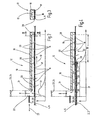
- FIGS. 2 to 4 clarify the vacuum holding device 12.
- the FIGS. 2 to 4 show a portion of the conveyor belt 6, which is permeable to air and / or - seen over its length - is provided with vacuum openings 16.
- the device 1 is formed as an overhead device, the vacuum holding device 12 is above the conveyor belt 6 of the lower run 9, ie, this runs along the bottom 17 of the vacuum holding device 12, preferably the materials of the conveyor belt 6 and the bottom 17 are chosen such that when sliding together only very small frictional forces occur.
- the vacuum holding device 12 has a strip-shaped main body 18, which extends along the longitudinal extent of the conveyor belt 6.
- the main body 18 is provided with an intake passage 19 which extends in the transport direction (arrow 13) and to the transport means 4, that is to the transport belt 6, is open over its entire longitudinal extent, that is, has a correspondingly long slot opening or - as in the embodiment of FIGS. 2 to 4 shown - with a plurality of spaced apart, over the longitudinal extent of the intake passage 19 arranged distributed openings 20 is provided.
- the intake duct 19 has only a very small, preferably square or rectangular cross section. This cross section may be constant over the longitudinal extension of the intake passage 19 or vary in size.
- a vacuum connection 22 In the region of its - in the transport direction (arrow 13) seen - good inlet side end 21 of the intake passage 19 is connected via a vacuum connection 22 to a vacuum source 23, which may be formed in particular as a fan 24.
- a switching valve 25 In the vacuum connection 22 is a switching valve 25 which is designed as a slide 26 which can be displaced by means of an actuator, not shown, in the direction of the double arrow 27. A displacement leads to the closing of the vacuum connection 22 or to its opening.
- the openings 20 are formed in a strip-shaped sliding plate 28, which has the underside 17, along which the transport belt 6 runs.
- the covered longitudinal extent of the intake duct 19 is a high level of negative pressure, since the largest amplitude of the maximum negative pressure with the Gutvorderkante 29 mitwandert, ie, the covered area of the intake 19 acts more like the vacuum connection 22 in the area in front of the Gutvorderkante 29th Guts 2 is a strong suction ensured by the bottleneck present there, so that the moved by means of the conveyor belt 6, front portion 30 is securely sucked and the entire Good 2 is firmly held on the transport means 4 in overhead position.
- the course of the negative pressure present for the distance is shown in the diagrams of FIGS. 2 and 4 designated by the reference numeral 31.
- the arrangement is inventively made such that at the Gutvorderkante 29 a transversely - in particular at right angles - to the transport direction (arrow 13) extending intake channel 34 forms within the intake passage 19, in the FIG. 4 indicated by dotted line.
- This Ansaugkanalquerites 34 is at an intake passage 19 with the same length throughout the length of a constant size. If the intake duct 19 seen over its length have a changing cross-section, so will also change with the Gutvorderkante 29 mitwandernde intake duct 34.
- the cross-section of the intake duct 19 decreases in the course of the longitudinal extent of the intake duct 19 extending in the direction of the arrow 13.
- an air passage cross-section 33 is present, which is formed at the transport means 4 in the area not covered by Good 2 and in the region of action of the intake passage 19.
- the air passage cross-section 33 therefore consists of the sum of the openings 20 present in the zone 35, taking into account the degree of separation with the vacuum openings 16.
- the air passage cross section 33 is dependent on the position of the product 2.
- this value is therefore not a constant size, since the openings 16 move past the openings 20, but in this respect a temporal mean value arises, which represents a corresponding air passage cross-section 33.
- FIG. 4 The intake passage 34 is at most equal to, preferably smaller than the respective associated air passage cross-section 33. This relationship applies at least over a partial length of the intake passage 19, in particular via a part length extending from the diligentinlauf solutionen end to just before the gutauslauf supra end of the intake passage 19.
- the invention relates to at least one intake duct 19 (vacuum duct), which makes it possible, as it were, to "walk along" the active intake cross section for the goods 2 without having to use movable control elements, such as rotary valves or valves or the like.
- the particular downwardly open intake duct (regardless of whether it is provided with a single slot opening or a plurality, distributed over the longitudinal extent arranged opening) preferably has a relatively small cross-section and is - as explained - evacuated in the region of the Guteinlaufs. With a free intake cross section of the intake duct 19, ie if there is no good 2, the air is sucked in predominantly in the region of the product inlet.
- the negative pressure field moves synchronously with the tabular material.
- a self-controlling intake duct in which the goods are held and, for example, braked, for example, by means of a perforated or several perforated transport belts. It can be a switching on and off of the negative pressure (vacuum), for example by means of a pneumatically actuated slide or a flap, these elements are in the vacuum connection.
- the suction channel can be connected via a hose as a vacuum connection 22 with the fan.
- the hose can for example have a diameter of 50 mm exhibit. Due to the relatively small fan no special or even no soundproofing measures are required. Overall, there is only a low energy consumption in the operation of the device.
- a magnetic holding device so that the holding device thus comprises a vacuum holding device and a magnetic holding device. Due to the magnetic effect of the magnetic holding device, which can be switched on and off, ferromagnetic goods can be additionally held.
- Such, purely magnetic effect-based holding device can also be upgraded with the inventive design, so transported not only ferromagnetic tabular goods, but also non-ferromagnetic goods and possibly discarded with such a device upgraded. This is important, for example, when goods are handled both for example steel sheet panels and aluminum sheet panels. Such an upgrade is possible without major modifications.
Landscapes
- Engineering & Computer Science (AREA)
- Mechanical Engineering (AREA)
- Sheets, Magazines, And Separation Thereof (AREA)
- Delivering By Means Of Belts And Rollers (AREA)
- Vending Machines For Individual Products (AREA)
- Belt Conveyors (AREA)
Description
- Die Erfindung betrifft eine Vorrichtung zum Transportieren von tafelförmigen Gütern, wie Blechtafeln oder dergleichen, mit einem Transportmittel und einer das jeweilige Gut an dem Transportmittel haltenden Halteeinrichtung, die als Unterdruckhalteeinrichtung ausgebildet ist, deren Unterdruck durch das Transportmittel hindurchwirkt.
- Eine Vorrichtung der eingangs genannten Art ist aus dem deutschen Gebrauchsmuster
DE 20 2008 004 820 U1 bekannt. Diese bekannte Vorrichtung weist eine Unterdruckhalteeinrichtung auf, bei der der Unterdruck sequenziell derart gesteuert wird, dass dieser lediglich im Bereich, in welchem sich das Gut befindet, anliegt. Um dies realisieren zu können, ist wenigstens ein Sensor zur Erfassung der Tafelvorderkante vor dem Unterdruckbereich vorgesehen, der ein Signal zum sequenziellen Unterdruckaufbau erzeugt. Der Aufbau des Unterdrucks erfolgt mit einer Luftsteuerwalze, die Nuten aufweist, die in Förderrichtung hin abnehmen. Dies bedeutet, dass eine erste Nut mit ihrer größten Länge über einen Zeitbereich Unterdruck erzeugt, der ausreicht, um das Gut bis zu seiner Endposition zu transportieren, während eine letzte Nut kurz gestaltet ist und erst dann wirksam wird, wenn die Nutvorderkante nahezu die Endposition erreicht hat. Diese Lösung hat den Nachteil, dass eine Vielzahl beweglicher Teile erforderlich ist und dass die Luftsteuerwalze synchron zum Gutvorderkanteneinlauf gesteuert werden muss. Die bekannte Vorrichtung ist daher relativ teuer und fehleranfällig im Betrieb. - Die
DE 33 43 811 A1 offenbart einen Saugriemenförderer, wobei in einer Platte Längsnuten angeordnet sind, über die ein mit Öffnungen versehener Riemen laufen kann. - Der Erfindung liegt daher die Aufgabe zugrunde, eine Vorrichtung zum Transportieren von tafelförmigen Gütern der eingangs genannten Art zu schaffen, die konstruktiv einfach und im Betrieb fehlerunanfällig ist.
- Diese Aufgabe wird erfindungsgemäß dadurch gelöst, dass die Unterdruckhalteeinrichtung mindestens einen sich in Transportrichtung oder im Wesentlichen in Transportrichtung erstreckenden, zum Transportmittel hin zumindest über einen Abschnitts einer Längserstreckung offenen Ansaugkanal aufweist, der im Bereich seines - in Transportrichtung gesehen - guteinlaufseitigen Endes an mindestens eine Unterdruckquelle angeschlossen ist, wobei am Transportmittel im vom Gut nicht abgedeckten Bereich des gutstellungsabhängig offenen Ansaugkanals ein Luftdurchtrittsquerschnitt vorliegt, und wobei ein sich quer, insbesondere rechtwinklig, zur Transportrichtung erstreckender, gegebenenfalls gutstellungsabhängiger Ansaugkanalquerschnitt an der Gutvorderkante eines an der Halteeinrichtung gehaltenen und transportierten Guts zumindest über eine Teillänge des Ansaugkanals maximal gleich groß wie oder kleiner als der jeweils zugehörige Luftdurchtrittsquerschnitt ist. Diese Ausgestaltung führt dazu, dass ein quasi selbststeuernder Unterdruckkanal durch fortschreitendes Abdecken des Ansaugkanals durch das transportierte Gut realisiert ist. Der zum Gut hin offene Ansaugkanal weist guteinlaufseitig den Anschluss an die Unterdruckquelle auf. Wird nun ein tafelförmiges Gut von der Transporteinrichtung gefördert, so überdeckt es fortschreitend den sich in Transportrichtung oder im Wesentlichen in Transportrichtung erstreckenden, zum Gut hin offenen Ansaugkanal und lässt damit ein Unterdruckmaximum des Unterdruckfelds mit der Gutvorderkante mitwandern. Das Maximum ergibt sich an der an der Gutvorderkante vorliegenden Engstelle, an der aufgrund des geringen Querschnitts ein entsprechend großer Druckabfall auftritt. Beim Gegenstand der Erfindung ist daher vorgesehen, dass sich die Engstelle im Bereich der Gutvorderkante befindet, wobei sie sich mit der Bewegung des Guts mitbewegt. Es ist zu berücksichtigen, dass der Luftdurchtrittsquerschnitt am Transportmittel, also der jeweils - in Abhängigkeit von der Stellung des Guts - im nicht abgedeckten Bereich des offenen Ansaugkanals momentan vorliegende Luftdurchtrittsquerschnitt eine veränderliche Größe ist. Je weiter die Vorderkante des Guts in Richtung auf das auslaufseitige Ende des Ansaugkanals gelangt, umso kleiner wird der Luftdurchtrittsquerschnitt. Ferner ist zu berücksichtigen, dass der an der Gutvorderkante vorliegende, sich quer, insbesondere rechtwinklig, zur Transportrichtung erstreckende Querschnitt des Ansaugkanals in seiner Größe abhängig sein kann von der jeweils betrachteten Stellung der Gutvorderkante, sofern der Ansaugkanal - über seine Länge betrachtet - nicht überall einen gleichgroßen Querschnitt aufweist. Erfindungsgemäß ist nun vorgesehen, dass zumindest über eine Teillänge des Ansaugkanals die erfindungsgemäßen Verhältnisse vorliegen, nämlich dass dort - im jeweils gutstellungsabhängig betrachteten Augenblick - der Ansaugkanalquerschnitt im Bereich der Gutvorderkante maximal gleich groß wie oder kleiner als der jeweils dazugehörige Luftdurchtrittsquerschnitt am Transportmittel ist. Ist der Luftdurchtrittsquerschnitt größer als der Ansaugkanalquerschnitt, so liegt die entscheidende, also kleinste, Engstelle im Ansaugkanal im Bereich der Vorderkante, mit der Folge, dass sich dort der größte Druckabfall ausbildet und insofern das Gut dadurch sicher gehalten wird, insbesondere ohne eine hohe Saugleistung der Unterdruckhalteeinrichtung zu benötigen, das heißt, der Energieeinsatz zum Betreiben der Unterdruckhalteeinrichtung kann relativ gering ausfallen und trotzdem wird eine hohe Haltewirkung erzielt. Auch wenn der Luftdurchtrittsquerschnitt ebenso groß wie der Ansaugkanalquerschnitt ist, ergeben sich noch die gewünschten positiven Wirkungen. Die Haltewirkung wandert mit der Gutvorderkante mit. Dieses "Mitwandern" des aktiven Ansaugquerschnitts wird ohne den Einsatz beweglicher Steuerelemente, wie die erwähnte Luftsteuerwalze des Standes der Technik, oder dergleichen geschaffen. Es ist vorteilhaft, wenn der Ansaugkanal einen relativ kleinen Querschnitt aufweist. Es können mehrere Ansaugkanäle vorgesehen sein. Die Anzahl der Ansaugkanäle ist in Abhängigkeit von dem Gewicht und den Abmessungen des tafelförmigen Guts wählbar. Mehrere derartige Ansaugkanäle verlaufen vorzugsweise beabstandet zueinander parallel. Der relativ kleine Querschnitt des Ansaugkanals beziehungsweise die relativ kleinen Querschnitte der Ansaugkanäle erfordern unter Berücksichtigung der erfindungsgemäßen Verhältnisse - wie erwähnt - nur eine klein dimensionierte Unterdruckquelle. Wird als Unterdruckquelle ein Ventilator eingesetzt, so kann er eine relativ kleine Bauform haben und hat daher nur einen geringen Energieverbrauch und erfordert keine oder nur geringe Schallschutzmaßnahmen, da er ein entsprechend leises Betriebsgeräusch aufweist.
- Nach einer Weiterbildung der Erfindung ist vorgesehen, dass der Ansaugkanal dadurch offen ist, dass er über seine Längserstreckung rinnenförmig ausgebildet und/oder über seine Längserstreckung mit Öffnungen versehen ist.
- Vorteilhaft ist ferner, wenn sich der Luftdurchtrittsquerschnitt aus dem jeweils momentan vorliegenden gutfreien und deckungsgleichen Durchtrittsquerschnitt des Transportmittels und Durchtrittsquerschnitt des Ansaugkanals ergibt.
- Nach einer Weiterbildung der Erfindung ist vorgesehen, dass die Unterdruckhalteeinrichtung als aktivierbare und deaktivierbare Unterdruckhalteeinrichtung zum Halten oder Freigeben der Güter ausgebildet ist. Im aktivierten Zustand wird das jeweilige Gut am Transportmittel gehalten; im deaktivierten Zustand wird das Gut freigegeben, sodass es beispielsweise bei der Ausgestaltung der Vorrichtung als Überkopfvorrichtung beim Freigeben vom Transportmittel durch Gravitationswirkung fällt und beispielsweise an einem Stapelort abgelegt wird.
- Es ist vorteilhaft, wenn die Unterdruckquelle über eine Unterdruckverbindung strömungstechnisch mit dem Ansaugkanal verbunden ist. Die Unterdruckverbindung stellt demzufolge eine Ansaugverbindung zum Ansaugkanal dar. In der Unterdruckverbindung kann zum Aktivieren und Deaktivieren der Unterdruckhalteeinrichtung ein Schaltventil, insbesondere ein verlagerbarer Schieber oder eine verlagerbare Klappe, vorgesehen sein. Wird das Schaltventil geschlossen, so ist die Unterdruckquelle nicht mehr mit dem Ansaugkanal verbunden, sodass sich der Unterdruck im Ansaugkanal abbaut und das Gut freigegeben wird. Ein Öffnen des Schaltventils führt demzufolge zum Aufbau des Unterdrucks im Ansaugkanal, wodurch das Gut am Transportmittel gehalten wird.
- Das Transportmittel weist mindestens einen Transportriemen auf. Vorzugsweise sind mindestens zwei parallel und mit Abstand zueinander verlaufende Transportriemen vorgesehen, an denen das jeweilige Gut, insbesondere die jeweilige Blechtafel, gehalten wird. Jeder der Transportriemen ist mit einem Ansaugkanal ausgestattet. Der mindestens eine, insbesondere die genannten beiden Transportriemen (oder noch weiteren parallel liegenden Transportriemen) gehören vorzugsweise einem Riementrum an, d.h., der Transportriemen beziehungsweise die Transportriemen laufen endlos um. Demgegenüber ist die Unterdruckhalteeinrichtung ortsfest installiert. Die Unterdruckhalteeinrichtung befindet sich auf einer Seite des Transportriemens/der Transportriemen und das zu haltende Gut befindet sich auf der anderen Seite des Transportriemens/der Transportriemen, wobei das Unterdruckfeld durch den Transportriemen/die Transportriemen hindurchwirkt. Demzufolge besteht das Transportmittel vorzugsweise aus luftdurchlässigem Material und/oder weist Unterdrucköffnungen auf.
- Wie bereits erwähnt, kann die Vorrichtung vorzugsweise als Überkopf-Vorrichtung zum Transport von tafelförmigen Gütern ausgebildet sein. Diese kann insbesondere einen Stapelbereich für von der deaktivieren Unterdruckhalteeinrichtung abgeworfene Güter aufweisen.
- Wie bereits erläutert, kann die Unterdruckquelle vorzugsweise als mindestens ein Ventilator ausgebildet sein.
- Nach einer Weiterbildung der Erfindung ist vorgesehen, dass der Kanalquerschnitt und damit der Ansaugkanalquerschnitt - über die Längserstreckung des Ansaugkanals betrachtet - gleich groß ist oder unterschiedlich groß ist, insbesondere in Richtung auf das gutauslaufseitige Ende des Ansaugkanals abnimmt.
- Die Zeichnungen veranschaulichen die Erfindung anhand eines Ausführungsbeispiels und zwar zeigt:
- Figur 1
- eine schematische Ansicht einer Vorrichtung zum Transportieren von tafelförmigen Gütern,
- Figur 2
- eine Längsschnittansicht durch eine Unterdruckhalteeinrichtung der Vorrichtung der
Figur 1 , - Figur 3
- einen Querschnitt durch die Unterdruckhalteeinrichtung der
Figur 2 entlang der Linie III-III und - Figur 4
- ein der
Figur 2 entsprechender Längsschnitt, jedoch mit einlaufendem, an einem Transportmittel gehaltenen tafelförmigen Gut. - Die
Figur 1 zeigt eine Vorrichtung 1 zum Transportieren von tafelförmigen Gütern 2, insbesondere Blechtafeln 3. Mit der Vorrichtung 1 lassen sich die Güter 2 transportieren und insbesondere als Stapel ablegen. - Die Vorrichtung 1 weist ein Transportmittel 4 in Form eines umlaufenden Trums 5 auf, das vorzugsweise als Riementrum ausgebildet ist. Das Trum 5 weist mehrere, seitliche beabstandet zueinander angeordnete Transportriemen 6 auf, wobei nachstehend nur auf einen Transportriemen 6 eingegangen wird. Die übrigen Transportriemen 6 sind gleichartig ausgestaltet und wirken mit gleichartigen, nachstehend noch näher beschriebenen Baugruppen zusammen, sodass es ausreicht, nur einen Transportriemen 6 mit den zugehörigen Baugruppen zu beschreiben.
- Der Transportriemen 6 wird über zwei Umlenkräder 7,8 geführt, von denen mindestens eines mittels eines nichtdargestellten Antriebs antreibbar ist. Das Untertrum 9 des Trums 5 ist außenseitig einer Stapelablage 10 für die Güter 2 zugewandt. Der Innenseite des von einem Abschnitt des Transportriemens 6 gebildeten Untertrums 9 ist eine Halteeinrichtung 11 zugeordnet. Die Halteeinrichtung 11 ist als Unterdruckhalteeinrichtung 12 ausgebildet und ortsfest angeordnet. Ist die Unterdruckhalteeinrichtung 12 aktiviert, so wird ein dem Trum 5 zugeführtes Gut 2 am Transportriemen 6, also am Untertrum 9, überkopf gehalten und entsprechend Pfeil 13 transportiert. Die Umlaufrichtung des Trums 5 ist mit einem Pfeil 14 verdeutlicht. Gelangt das Gut 2 in den Bereich der Stapelablage 10, so wird die Umlaufgeschwindigkeit des Trums 5 reduziert, vorzugsweise bis zum Stillstand, und anschließend die Unterdruckhalteeinrichtung 12 deaktiviert, wodurch das Gut 2 freigegeben und gemäß Pfeil 15 auf der Stapelablage 10 durch Herabfallen abgelegt wird.
- Die
Figuren 2 bis 4 verdeutlichen die Unterdruckhalteeinrichtung 12. DieFiguren 2 bis 4 zeigen einen Abschnitt des Transportriemens 6, der luftdurchlässig ausgebildet ist und/oder - über seine Länge gesehen - mit Unterdrucköffnungen 16 versehen ist. Da - wie insbesondere derFigur 1 zu entnehmen ist - die Vorrichtung 1 als Überkopf-Vorrichtung ausgebildet ist, befindet sich die Unterdruckhalteeinrichtung 12 oberhalb des Transportriemens 6 des Untertrums 9, d.h., dieser läuft entlang der Unterseite 17 der Unterdruckhalteeinrichtung 12, wobei vorzugsweise die Materialien des Transportriemens 6 und der Unterseite 17 derart gewählt sind, dass bei einem Aneinandergleiten nur sehr kleine Reibungskräfte auftreten. - Die Unterdruckhalteeinrichtung 12 weist einen leistenförmigen Grundkörper 18 auf, der sich entlang der Längserstreckung des Transportriemens 6 erstreckt. Der Grundkörper 18 ist mit einem Ansaugkanal 19 versehen, der sich in Transportrichtung (Pfeil 13) erstreckt und zum Transportmittel 4, also zum Transportriemen 6, hin über seine gesamte Längserstreckung offen ist, also eine entsprechend lange Schlitzöffnung aufweist oder - wie im Ausführungsbeispiel der
Figuren 2 bis 4 dargestellt - mit einer Vielzahl von beabstandet zueinander liegenden, über die Längserstreckung des Ansaugkanals 19 verteilt angeordneten Öffnungen 20 versehen ist. GemäßFigur 3 weist der Ansaugkanal 19 nur einen sehr kleinen, vorzugsweise quadratischen oder rechteckigen Querschnitt auf. Dieser Querschnitt kann über die Längserstreckung des Ansaugkanals 19 konstant sein oder auch in der Größe variieren. - Im Bereich seines - in Transportrichtung (Pfeil 13) gesehenen - guteinlaufseitigen Endes 21 ist der Ansaugkanal 19 über eine Unterdruckverbindung 22 an eine Unterdruckquelle 23 angeschlossen, die insbesondere als Ventilator 24 ausgebildet sein kann. In der Unterdruckverbindung 22 befindet sich ein Schaltventil 25, das als Schieber 26 ausgebildet ist, der mittels eines nicht dargestellten Aktors in Richtung des Doppelpfeils 27 verlagert werden kann. Eine Verlagerung führt zum Verschließen der Unterdruckverbindung 22 beziehungsweise zu deren Öffnen. Die Öffnungen 20 sind in einer streifenförmigen Gleitplatte 28 ausgebildet, die die Unterseite 17 aufweist, an der der Transportriemen 6 entlangläuft.
- Wird ein tafelförmiges Gut 2 der in Betrieb befindlichen Vorrichtung 1 gemäß
Figur 1 von einer vorgelagerten, nicht dargestellten Einrichtung zugeführt, so gelangt der eine Gutvorderkante 29 aufweisende vordere Bereich 30 des Guts 2 in den Wirkungsbereich der Unterdruckhalteeinrichtung 12. Es wird davon ausgegangen, dass zunächst, also wenn die Gutvorderkante 29 die Unterdruckhalteeinrichtung 12 noch nicht erreicht hat, die Verhältnisse gemäßFigur 2 vorliegen. Dort ist erkennbar, dass - bei in Offenstellung verlagertem Schaltventil 25 - die Unterdruckquelle 23 einen Unterdruck im Ansaugkanal 19 herstellt, der einen in einem unterhalb der Unterdruckhalteeinrichtung 12 derFigur 2 dargestellten Diagramm gezeigten Verlauf aufweist. In denFiguren 2 bis 4 wird bei den eingetragenen, durch den Unterdruck bewirkten Strömungspfeilen nicht berücksichtigt, dass sich die Unterdrucköffnungen 16 an den Öffnungen 20 vorbeibewegen, sodass nicht ständig eine Offenstellung vorliegt, sondern auch Überdeckungssituationen, die jedoch im zeitlichen Mittel nicht von Bedeutung sind. Um möglichst Überdeckungssituationen zu minimieren, können Langlöcher vorgesehen sein, zwischen denen nur schmale Trennstege ausgebildet sind. Die Pfeillängen der die Öffnungen 16 und 20 durchsetzenden, das Ansaugen verdeutlichten Pfeile verdeutlichen, dass im Bereich des guteinlaufseitigen Endes 21 des Ansaugkanals 19 das sich ausbildende Unterdruckfeld die größte Druckdifferenz aufweist. Über die Längserstreckung des Ansaugkanals 19 gesehen, steigt der Unterdruck im Bereich der Unterdruckverbindung 22 stark an, erreicht dann sein Maximum etwa auf Höhe der Unterdruckverbindung 22 und fällt dann - gutstromabwärts der Unterdruckverbindung 22 - wieder zügig ab. Wird nun-wie vorstehend bereits angedeutet - ein Gut 2 zugeführt, so gelangt dessen vorderer Bereich 30 in den Wirkungsbereich des Unterdrucks der Unterdruckhalteeinrichtung 12, so wie dies aus der Momentsituation derFigur 4 hervorgeht. Dort ist ersichtlich, dass die Gutvorderkante 29 des durch Unterdruck am Transportriemen 6 gehaltenen Guts 2 bereits bis etwa in den mittleren Bereich der Längserstreckung des Ansaugkanals 19 (gemäß Pfeil 13) verlagert wurde. Dabei werden durch das luftundurchlässige Gut 2 die bereits passierten Öffnungen 20 abgedeckt, mit der Folge, dass sich gemäß dem Diagramm derFigur 4 ein entsprechendes Unterdruckfeld aufbaut, das gegenüber dem Unterdruckverlauf derFigur 2 unterschiedlich ist. Entlang der abgedeckten Längserstreckung des Ansaugkanals 19 liegt ein hoher Level des Unterdrucks vor, da die größte Amplitude des maximalen Unterdrucks quasi mit der Gutvorderkante 29 mitwandert, d.h., der abgedeckte Bereich des Ansaugkanals 19 wirkt quasi wie die Unterdruckverbindung 22. Im Bereich vor der Gutvorderkante 29 des Guts 2 ist ein starkes Ansaugen durch die dort vorliegende Engstelle sichergestellt, sodass der mittels des Transportriemens 6 bewegte, vordere Bereich 30 sicher angesaugt und das gesamte Gut 2 fest am Transportmittel 4 in Überkopfposition gehalten ist. Der für die Wegstrecke jeweils vorliegende Verlauf des Unterdrucks ist in den Diagrammen derFiguren 2 und 4 mit dem Bezugszeichen 31 gekennzeichnet. Die Anordnung ist erfindungsgemäß derart getroffen, dass sich an der Gutvorderkante 29 ein quer - insbesondere rechtwinklig - zur Transportrichtung (Pfeil 13) erstreckender Ansaugkanalquerschnitt 34 innerhalb des Ansaugkanals 19 ausbildet, der in derFigur 4 mit gepunkteter Linie angedeutet ist. Dieser Ansaugkanalquerschnitt 34 ist bei einem Ansaugkanal 19 mit über die Länge überall gleichgroßem Querschnitt eine konstante Größe. Sollte der Ansaugkanal 19 über seine Länge gesehen einen sich verändernden Querschnitt aufweisen, so wird sich auch dementsprechend der mit der Gutvorderkante 29 mitwandernde Ansaugkanalquerschnitt 34 ändern. In einem speziellen, nicht dargestellten Ausführungsbeispiel kann vorgesehen sein, dass sich der Querschnitt des Ansaugkanals 19 im Zuge der in Richtung des Pfeils 13 verlaufenden Längserstreckung des Ansaugkanals 19 verkleinert. Ferner ist zu berücksichtigen, dass sich in einer im Zuge des Transports des Guts 2 in der Größe verändernden Zone 35, die von der Gutvorderkante 29 bis zum gutauslaufseitigen Ende des Ansaugkanals 19 verläuft, ein Luftdurchtrittsquerschnitt 33 vorliegt, der am Transportmittel 4 im vom Gut 2 nicht abgedeckten Bereich sowie im Wirkungsbereich des Ansaugkanals 19 gebildet wird. Der Luftdurchtrittsquerschnitt 33 besteht demzufolge aus der Summe der in der Zone 35 vorliegenden Öffnungen 20 unter Berücksichtigung des Fluchtungsgrads mit den Unterdrucköffnungen 16. Der Luftdurchtrittsquerschnitt 33 ist von der Stellung des Guts 2 abhängig. Ferner ist dieser Wert zusätzlich deshalb keine konstante Größe, da sich die Öffnungen 16 an den Öffnungen 20 vorbeibewegen, jedoch stellt sich insoweit ein zeitlicher Mittelwert ein, der einen entsprechenden Luftdurchtrittsquerschnitt 33 repräsentiert. Erfindungsgemäß ist vorgesehen, dass - entsprechendFigur 4 - der Ansaugkanalquerschnitt 34 maximal gleichgroß wie, vorzugsweise kleiner als der jeweils zugehörige Luftdurchtrittsquerschnitt 33 ist. Diese Beziehung gilt zumindest über eine Teillänge des Ansaugkanals 19, insbesondere über eine sich vom guteinlaufseitigen Ende bis kurz vor das gutauslaufseitige Ende des Ansaugkanals 19 erstreckende Teillänge. Hierdurch ist stets sichergestellt, dass an der Gutvorderkante 29 die kleinste Engstelle der gesamten Unterdruckanordnung vorliegt, mit der Folge, dass dort der größte Druckabfall entsteht und dadurch ermöglicht ist, mit relativ kleiner Saugleistung eine hinreichend große Haltekraft zum sicheren Halten des Guts 2 am Transportmittel 4 zu schaffen. - Gelangt das Gut 2 in den Bereich der Stapelablage 10 (
Figur 1 ), so wird die Umlaufgeschwindigkeit des Trums 5 reduziert, vorzugsweise bis zum Stillstand, und anschließend die Unterdruckhalteeinrichtung 12 deaktiviert, indem der Schieber 26 in Schließstellung verlagert wird. Hierdurch wird das Gut 2 freigegeben und gemäß Pfeil 15 auf der Stapelablage 10 durch Herabfallen abgelegt. Anschließend beschleunigt das Trum 5 wieder und übernimmt ein Folgegut und so weiter. - Die Erfindung betrifft demgemäß mindestens einen Ansaugkanal 19 (Vakuumkanal), der quasi ein "Mitwandern" des aktiven Ansaugquerschnitts für das Gut 2 ermöglicht, ohne dass bewegliche Steuerelemente, wie Drehschieber oder Ventile oder dergleichen, eingesetzt werden müssen. Der insbesondere nach unten offene Ansaugkanal (unabhängig davon, ob er mit einer einzigen Schlitzöffnung versehen ist oder mehrere, über die Längserstreckung verteilt angeordnete Öffnung aufweist) hat vorzugsweise einen relativ kleinen Querschnitt und wird - wie erläutert - im Bereich des Guteinlaufs evakuiert. Bei freiem Ansaugquerschnitt des Ansaugkanals 19, wenn sich also dort kein Gut 2 befindet, wird die Luft überwiegend im Bereich des Guteinlaufs angesaugt. Wird der Ansaugkanal 19 zusehends durch das transportierte Gut 2 abgedeckt, so wandert das Unterdruckfeld synchron zum tafelförmigen Gut mit. Es liegt daher ein selbststeuernder Ansaugkanal (Vakuumkanal) vor, bei dem das Gut beispielsweise mittels eines gelochten oder mehrerer gelochter Transportriemen gehalten und beispielsweise abgebremst wird. Es kann ein Ein- und Ausschalten des Unterdrucks (Vakuums) erfolgen, beispielsweise mittels eines pneumatisch betätigbaren Schiebers oder einer Klappe, wobei sich diese Elemente in der Unterdruckverbindung befinden.
- Aufgrund der Erfindung kommt es gegenüber dem Stand der Technik zu Kosteneinsparungen, da keine aufwendig herzustellende Luftsteuerwalze erforderlich ist. Der Ansaugkanal lässt sich über einen Schlauch als Unterdruckverbindung 22 mit dem Ventilator verbinden. Der Schlauch kann beispielsweise einen Durchmesser von 50 mm aufweisen. Aufgrund des relativ kleinen Ventilators sind keine besonderen oder sogar gar keine Schallschutzmaßnahmen erforderlich. Insgesamt liegt im Betrieb der Vorrichtung nur ein geringer Energieverbrauch vor.
- Selbstverständlich ist es möglich, zusätzlich eine Magnethalteeinrichtung vorzusehen, sodass die Halteeinrichtung also eine Unterdruckhalteeinrichtung und eine Magnethalteeinrichtung umfasst. Aufgrund der Magnetwirkung der Magnethalteeinrichtung, die ein- und ausschaltbar ist, lassen sich ferromagnetische Güter zusätzlich halten. Derartige, rein auf Magnetwirkung basierende Halteeinrichtung können ferner mit der erfindungsgemäßen Ausgestaltung aufgerüstet werden, sodass mit einer derartig aufgerüsteten Vorrichtung nicht nur ferromagnetische tafelförmige Güter, sondern auch nicht ferromagnetische Güter transportiert und gegebenenfalls abgeworfen werden können. Dies ist beispielsweise dann von Bedeutung, wenn als Güter sowohl zum Beispiel Stahlblechtafeln als auch Aluminiumblechtafeln gehandhabt werden. Eine derartige Aufrüstung ist ohne große Umbaumaßnahmen möglich.
Claims (11)
- Vorrichtung zum Transportieren von tafelförmigen Gütern, wie Blechtafeln, mit einem Transportmittel und einer das jeweilige Gut an dem Transportmittel haltenden Halteeinrichtung, die als Unterdruckhalteeinrichtung ausgebildet ist, deren Unterdruck durch das Transportmittel hindurchwirkt, wobei die Unterdruckhalteeinrichtung (12) mindestens einen sich in Transportrichtung erstreckenden, zum Transportmittel (4) hin zumindest über einen Abschnitt seiner Längserstreckung offenen Ansaugkanal (19) aufweist, der im Bereich seines in Transportrichtung gesehen guteinlaufseitigen Endes (21) an mindestens eine Unterdruckquelle (23) angeschlossen ist, wobei am Transportmittel (4) im vom Gut (2) nicht abgedeckten Bereich (Zone 35) des gutstellungsabhängig offenen Ansaugkanals (19) ein Luftdurchtrittsquerschnitt (33) vorliegt, und wobei ein sich quer zur Transportrichtung erstreckender, gegebenenfalls gutstellungsabhängiger Ansaugkanalquerschnitt (34) an der Gutvorderkante (29) eines an der Halteeinrichtung (11) gehaltenen und transportierten Guts (2) zumindest über eine Teillänge des Ansaugkanals (19) maximal gleich groß wie oder kleiner als der jeweils zugehörige Luftdurchtrittsquerschnitt (33) ist, dass der Ansaugkanal (19) dadurch offen ist, dass er über seine Längserstreckung mit Öffnungen (20) versehen ist, wobei das Transportmittel (4) mindestens einen Transportriemen (6) aufweist, wobei der Transportriemen (6) über seine Länge gesehen mit Unterdrucköffnungen (16) versehen ist und wobei der Luftdurchtrittsquerschnitt (33) aus der Summe der in der Zone (35) vorliegenden Öffnungen (20) unter Berücksichtigung des Fluchtungsgrads mit den Unterdrucköffnungen (16) besteht.
- Vorrichtung nach einem der vorhergehenden Ansprüche, dadurch gekennzeichnet, dass die Unterdruckhalteeinrichtung (12) als aktivierbare und deaktivierbare Unterdruckhalteeinrichtung (12) zum Halten oder Freigeben der Güter (2) ausgebildet ist.
- Vorrichtung nach einem der vorhergehenden Ansprüche, dadurch gekennzeichnet, dass die Unterdruckquelle (23) über eine Unterdruckverbindung (22) strömungstechnisch mit dem Ansaugkanal (19) verbunden ist.
- Vorrichtung nach einem der vorhergehenden Ansprüche, dadurch gekennzeichnet, dass in der Unterdruckverbindung (22) zum Aktivieren und Deaktivieren der Unterdruckhalteeinrichtung (12) ein Schaltventil (25), insbesondere ein verlagerbarer Schieber (26) oder eine verlagerbare Klappe, angeordnet ist.
- Vorrichtung nach einem der vorhergehenden Ansprüche, dadurch gekennzeichnet, dass der Transportriemen (6) einem Trum (5) angehört.
- Vorrichtung nach einem der vorhergehenden Ansprüche, gekennzeichnet durch die Ausbildung als Überkopf-Vorrichtung.
- Vorrichtung nach einem der vorhergehenden Ansprüche, gekennzeichnet durch einen Stapelbereich für von der deaktivierten Unterdruckhalteeinrichtung (12) abgeworfene Güter (2).
- Vorrichtung nach einem der vorhergehenden Ansprüche, dadurch gekennzeichnet, dass die Unterdruckquelle (23) als mindestens ein Ventilator (24) ausgebildet ist.
- Vorrichtung nach einem der vorhergehenden Ansprüche, dadurch gekennzeichnet, dass der Kanalquerschnitt und damit der Ansaugkanalquerschnitt (34) über die Längserstreckung des Ansaugkanals (19) betrachtet gleich groß ist oder unterschiedlich groß ist.
- Vorrichtung nach einem der vorhergehenden Ansprüche, dadurch gekennzeichnet, dass der Kanalquerschnitt und damit der Ansaugkanalquerschnitt (34) über die Längserstreckung des Ansaugkanals (19) betrachtet in Richtung auf das gutauslaufseitige Ende des Ansaugkanals (19) abnimmt.
- Vorrichtung nach einem der vorhergehenden Ansprüche, dadurch gekennzeichnet, dass sich der Ansaugkanalquerschnitt (34) rechtwinklig zur Transportrichtung erstreckt.
Applications Claiming Priority (2)
| Application Number | Priority Date | Filing Date | Title |
|---|---|---|---|
| DE102009019785.0A DE102009019785B4 (de) | 2009-05-02 | 2009-05-02 | Vorrichtung zum Transportieren von tafelförmigen Gütern |
| PCT/EP2010/001856 WO2010127745A2 (de) | 2009-05-02 | 2010-03-25 | Vorrichtung zum transportieren von tafelförmigen gütern |
Publications (2)
| Publication Number | Publication Date |
|---|---|
| EP2424797A2 EP2424797A2 (de) | 2012-03-07 |
| EP2424797B1 true EP2424797B1 (de) | 2013-08-28 |
Family
ID=42932348
Family Applications (1)
| Application Number | Title | Priority Date | Filing Date |
|---|---|---|---|
| EP10736603.1A Not-in-force EP2424797B1 (de) | 2009-05-02 | 2010-03-25 | Vorrichtung zum transportieren von tafelförmigen gütern |
Country Status (5)
| Country | Link |
|---|---|
| EP (1) | EP2424797B1 (de) |
| CN (1) | CN102414096B (de) |
| DE (1) | DE102009019785B4 (de) |
| ES (1) | ES2432715T3 (de) |
| WO (1) | WO2010127745A2 (de) |
Families Citing this family (6)
| Publication number | Priority date | Publication date | Assignee | Title |
|---|---|---|---|---|
| ES2729526T3 (es) * | 2016-01-07 | 2019-11-04 | Fagor Arrasate S Coop | Dispositivo de transporte de piezas y método para transportar piezas |
| TWI590371B (zh) * | 2016-05-19 | 2017-07-01 | 由田新技股份有限公司 | 真空吸附移載設備及其真空吸附載台 |
| CN106628857A (zh) * | 2017-02-22 | 2017-05-10 | 东莞裕保电子精密设备有限公司 | 吸附式风道送料装置 |
| CN111573136B (zh) * | 2020-05-20 | 2022-01-07 | 济南和拓自动化科技有限公司 | 一种物料输送装置 |
| CN118323731B (zh) * | 2024-06-13 | 2024-09-10 | 徐州日托光伏科技有限公司 | 一种光伏板传输单元及其输送线 |
| DE202025107819U1 (de) | 2025-12-18 | 2026-05-07 | Neuhäuser GmbH | Vorrichtung zum Transport von Werkstücken |
Family Cites Families (9)
| Publication number | Priority date | Publication date | Assignee | Title |
|---|---|---|---|---|
| US3845950A (en) * | 1968-11-22 | 1974-11-05 | B Kuzniak | Material handling apparatus |
| FR2041277A5 (de) * | 1969-04-18 | 1971-01-29 | Kuzniak Bernard | |
| DE3343811A1 (de) * | 1983-12-03 | 1985-06-13 | Babcock-BSH AG vormals Büttner-Schilde-Haas AG, 4150 Krefeld | Saugriemenfoerderer |
| JP3366787B2 (ja) * | 1995-10-20 | 2003-01-14 | ノーリツ鋼機株式会社 | 感光材料の吸着搬送装置 |
| DE19636160A1 (de) * | 1996-09-06 | 1998-03-12 | Nsm Magnettechnik Gmbh | Bandfördereinrichtung für die hängende Beförderung von Transportgütern mit Unterdruck |
| DE19636161A1 (de) * | 1996-09-06 | 1998-03-12 | Nsm Magnettechnik Gmbh | Förderband für einen Endlosförderer mit Unterdruckeinrichtung |
| DE19732196A1 (de) * | 1997-07-26 | 1999-01-28 | Hauni Maschinenbau Ag | Saugstrangförderer für eine Zigarettenstrangmaschine |
| DE10122032B4 (de) * | 2001-05-07 | 2004-10-14 | Eckhard Polman | Bandfördervorrichtung |
| DE202008004820U1 (de) | 2008-04-07 | 2008-08-21 | Eble, Markus | Transportvorrichtung zum Führen und Ablegen von Tafeln |
-
2009
- 2009-05-02 DE DE102009019785.0A patent/DE102009019785B4/de not_active Expired - Fee Related
-
2010
- 2010-03-25 ES ES10736603T patent/ES2432715T3/es active Active
- 2010-03-25 EP EP10736603.1A patent/EP2424797B1/de not_active Not-in-force
- 2010-03-25 WO PCT/EP2010/001856 patent/WO2010127745A2/de not_active Ceased
- 2010-03-25 CN CN201080019464.7A patent/CN102414096B/zh not_active Expired - Fee Related
Also Published As
| Publication number | Publication date |
|---|---|
| CN102414096B (zh) | 2014-05-21 |
| DE102009019785B4 (de) | 2016-12-22 |
| DE102009019785A1 (de) | 2010-11-11 |
| WO2010127745A2 (de) | 2010-11-11 |
| ES2432715T3 (es) | 2013-12-04 |
| EP2424797A2 (de) | 2012-03-07 |
| CN102414096A (zh) | 2012-04-11 |
| WO2010127745A3 (de) | 2011-01-27 |
Similar Documents
| Publication | Publication Date | Title |
|---|---|---|
| DE102009019785B4 (de) | Vorrichtung zum Transportieren von tafelförmigen Gütern | |
| EP0451702B1 (de) | Bogenanleger | |
| DE202008004820U1 (de) | Transportvorrichtung zum Führen und Ablegen von Tafeln | |
| DE19636160A1 (de) | Bandfördereinrichtung für die hängende Beförderung von Transportgütern mit Unterdruck | |
| DE10213705C5 (de) | Vorrichtung zum Fördern eines Bogenstroms von einem Bogenstapel zu einer bogenverarbeitenden Maschine | |
| EP2841365B1 (de) | Saugfördervorrichtung zum transport von flachteilen, und anlage zum herstellen von flachteilen umfassend einer solchen saugfördervorrichtung | |
| DE102012108198B4 (de) | Vorrichtung zum Absaugen von Abfallprodukten einer Produktionsmaschine mit einem Absaugelement | |
| DE102012013517A1 (de) | Vorrichtung und Verfahren zum Vereinzeln von Wertdokumenten, sowie Wertdokumentbearbeitungssystem | |
| DE10122032A1 (de) | Bandfördervorrichtung | |
| EP3401245B1 (de) | Saugnapfvorrichtung und saugförderer mit einer derartigen saugnapfvorrichtung | |
| DE4424483A1 (de) | Ausleger einer bogenverarbeitenden Maschine | |
| DE19510364A1 (de) | Vorrichtung zum Bearbeiten von Blattlagen oder dergleichen | |
| DE102005050687B4 (de) | Vorrichtung für den insbesondere hängenden Transport von Transportgütern mittels Unterdruck | |
| EP2620400B1 (de) | Transportsystem zum Transport von Blechtafeln in eine Blechdruckmaschine oder Blechlackiermaschine | |
| LU101646B1 (de) | Fördervorrichtung mit einem endlos umlaufenden Förderriemen zum Fördern einer Transporteinrichtung, mittels der ein Fördergut transportierbar ist | |
| EP1398283B1 (de) | Transportvorrichtung für Gegenstände sowie Verfahren zum Halten oder Loslassen der Gegenstände | |
| EP1717179B1 (de) | Vorrichtung für ein Stabilisieren von in einem Förderstrom über eine Wegstrecke in Klammern einer Fördervorrichtung hängend transportierten Druckprodukten | |
| DE102008017753B4 (de) | Transportvorrichtung zum Führen und Ablegen von Tafeln | |
| WO2013160402A1 (de) | Entnahmevorrichtung zur entnahme von flachteilen | |
| DE29718611U1 (de) | Bandfördereinrichtung für die hängende Beförderung von Transportgütern mit Unterdruck | |
| DE202008018496U1 (de) | Transportsystem sowie Vorrichtung zum Transport von Blechtafeln in eine Blechdruckmaschine oder Blechlackiermaschine | |
| DE202008018495U1 (de) | Blechtafel-Saugvorrichtung und Vorrichtung zum Transport von Blechtafeln in eine Blechdruckmaschine oder Blechlackiermaschine sowie Blechtafel-Transportsystem | |
| DE29718610U1 (de) | Förderband für einen Endlosförderer mit Unterdruckeinrichtung | |
| EP4321780A1 (de) | Schieberventil, modul mit einem ventil und anlage zum fördern von schüttgut mit ventilen | |
| DE20108190U1 (de) | Anlage zum Transport von Objekten auf Förderbahnen mittels einer Transportrolle |
Legal Events
| Date | Code | Title | Description |
|---|---|---|---|
| PUAI | Public reference made under article 153(3) epc to a published international application that has entered the european phase |
Free format text: ORIGINAL CODE: 0009012 |
|
| 17P | Request for examination filed |
Effective date: 20110909 |
|
| AK | Designated contracting states |
Kind code of ref document: A2 Designated state(s): AT BE BG CH CY CZ DE DK EE ES FI FR GB GR HR HU IE IS IT LI LT LU LV MC MK MT NL NO PL PT RO SE SI SK SM TR |
|
| DAX | Request for extension of the european patent (deleted) | ||
| GRAP | Despatch of communication of intention to grant a patent |
Free format text: ORIGINAL CODE: EPIDOSNIGR1 |
|
| GRAJ | Information related to disapproval of communication of intention to grant by the applicant or resumption of examination proceedings by the epo deleted |
Free format text: ORIGINAL CODE: EPIDOSDIGR1 |
|
| RIN1 | Information on inventor provided before grant (corrected) |
Inventor name: MICHEL, BJOERN |
|
| 17Q | First examination report despatched |
Effective date: 20121219 |
|
| GRAP | Despatch of communication of intention to grant a patent |
Free format text: ORIGINAL CODE: EPIDOSNIGR1 |
|
| INTG | Intention to grant announced |
Effective date: 20130507 |
|
| GRAS | Grant fee paid |
Free format text: ORIGINAL CODE: EPIDOSNIGR3 |
|
| GRAA | (expected) grant |
Free format text: ORIGINAL CODE: 0009210 |
|
| RIN1 | Information on inventor provided before grant (corrected) |
Inventor name: MICHEL, BJOERN |
|
| AK | Designated contracting states |
Kind code of ref document: B1 Designated state(s): AT BE BG CH CY CZ DE DK EE ES FI FR GB GR HR HU IE IS IT LI LT LU LV MC MK MT NL NO PL PT RO SE SI SK SM TR |
|
| REG | Reference to a national code |
Ref country code: GB Ref legal event code: FG4D Free format text: NOT ENGLISH |
|
| REG | Reference to a national code |
Ref country code: CH Ref legal event code: EP |
|
| REG | Reference to a national code |
Ref country code: AT Ref legal event code: REF Ref document number: 629204 Country of ref document: AT Kind code of ref document: T Effective date: 20130915 |
|
| REG | Reference to a national code |
Ref country code: IE Ref legal event code: FG4D Free format text: LANGUAGE OF EP DOCUMENT: GERMAN |
|
| REG | Reference to a national code |
Ref country code: DE Ref legal event code: R096 Ref document number: 502010004526 Country of ref document: DE Effective date: 20131024 |
|
| REG | Reference to a national code |
Ref country code: ES Ref legal event code: FG2A Ref document number: 2432715 Country of ref document: ES Kind code of ref document: T3 Effective date: 20131204 |
|
| REG | Reference to a national code |
Ref country code: LT Ref legal event code: MG4D |
|
| REG | Reference to a national code |
Ref country code: NL Ref legal event code: VDEP Effective date: 20130828 |
|
| PG25 | Lapsed in a contracting state [announced via postgrant information from national office to epo] |
Ref country code: NO Free format text: LAPSE BECAUSE OF FAILURE TO SUBMIT A TRANSLATION OF THE DESCRIPTION OR TO PAY THE FEE WITHIN THE PRESCRIBED TIME-LIMIT Effective date: 20131128 Ref country code: HR Free format text: LAPSE BECAUSE OF FAILURE TO SUBMIT A TRANSLATION OF THE DESCRIPTION OR TO PAY THE FEE WITHIN THE PRESCRIBED TIME-LIMIT Effective date: 20130828 Ref country code: SE Free format text: LAPSE BECAUSE OF FAILURE TO SUBMIT A TRANSLATION OF THE DESCRIPTION OR TO PAY THE FEE WITHIN THE PRESCRIBED TIME-LIMIT Effective date: 20130828 Ref country code: CY Free format text: LAPSE BECAUSE OF FAILURE TO SUBMIT A TRANSLATION OF THE DESCRIPTION OR TO PAY THE FEE WITHIN THE PRESCRIBED TIME-LIMIT Effective date: 20130814 Ref country code: PT Free format text: LAPSE BECAUSE OF FAILURE TO SUBMIT A TRANSLATION OF THE DESCRIPTION OR TO PAY THE FEE WITHIN THE PRESCRIBED TIME-LIMIT Effective date: 20131230 Ref country code: LT Free format text: LAPSE BECAUSE OF FAILURE TO SUBMIT A TRANSLATION OF THE DESCRIPTION OR TO PAY THE FEE WITHIN THE PRESCRIBED TIME-LIMIT Effective date: 20130828 Ref country code: IS Free format text: LAPSE BECAUSE OF FAILURE TO SUBMIT A TRANSLATION OF THE DESCRIPTION OR TO PAY THE FEE WITHIN THE PRESCRIBED TIME-LIMIT Effective date: 20131228 |
|
| REG | Reference to a national code |
Ref country code: NL Ref legal event code: VDEP Effective date: 20130828 |
|
| PG25 | Lapsed in a contracting state [announced via postgrant information from national office to epo] |
Ref country code: GR Free format text: LAPSE BECAUSE OF FAILURE TO SUBMIT A TRANSLATION OF THE DESCRIPTION OR TO PAY THE FEE WITHIN THE PRESCRIBED TIME-LIMIT Effective date: 20131129 Ref country code: FI Free format text: LAPSE BECAUSE OF FAILURE TO SUBMIT A TRANSLATION OF THE DESCRIPTION OR TO PAY THE FEE WITHIN THE PRESCRIBED TIME-LIMIT Effective date: 20130828 Ref country code: PL Free format text: LAPSE BECAUSE OF FAILURE TO SUBMIT A TRANSLATION OF THE DESCRIPTION OR TO PAY THE FEE WITHIN THE PRESCRIBED TIME-LIMIT Effective date: 20130828 Ref country code: SI Free format text: LAPSE BECAUSE OF FAILURE TO SUBMIT A TRANSLATION OF THE DESCRIPTION OR TO PAY THE FEE WITHIN THE PRESCRIBED TIME-LIMIT Effective date: 20130828 Ref country code: LV Free format text: LAPSE BECAUSE OF FAILURE TO SUBMIT A TRANSLATION OF THE DESCRIPTION OR TO PAY THE FEE WITHIN THE PRESCRIBED TIME-LIMIT Effective date: 20130828 |
|
| PG25 | Lapsed in a contracting state [announced via postgrant information from national office to epo] |
Ref country code: CY Free format text: LAPSE BECAUSE OF FAILURE TO SUBMIT A TRANSLATION OF THE DESCRIPTION OR TO PAY THE FEE WITHIN THE PRESCRIBED TIME-LIMIT Effective date: 20130828 |
|
| PG25 | Lapsed in a contracting state [announced via postgrant information from national office to epo] |
Ref country code: CZ Free format text: LAPSE BECAUSE OF FAILURE TO SUBMIT A TRANSLATION OF THE DESCRIPTION OR TO PAY THE FEE WITHIN THE PRESCRIBED TIME-LIMIT Effective date: 20130828 Ref country code: EE Free format text: LAPSE BECAUSE OF FAILURE TO SUBMIT A TRANSLATION OF THE DESCRIPTION OR TO PAY THE FEE WITHIN THE PRESCRIBED TIME-LIMIT Effective date: 20130828 Ref country code: RO Free format text: LAPSE BECAUSE OF FAILURE TO SUBMIT A TRANSLATION OF THE DESCRIPTION OR TO PAY THE FEE WITHIN THE PRESCRIBED TIME-LIMIT Effective date: 20130828 Ref country code: SK Free format text: LAPSE BECAUSE OF FAILURE TO SUBMIT A TRANSLATION OF THE DESCRIPTION OR TO PAY THE FEE WITHIN THE PRESCRIBED TIME-LIMIT Effective date: 20130828 Ref country code: NL Free format text: LAPSE BECAUSE OF FAILURE TO SUBMIT A TRANSLATION OF THE DESCRIPTION OR TO PAY THE FEE WITHIN THE PRESCRIBED TIME-LIMIT Effective date: 20130828 Ref country code: DK Free format text: LAPSE BECAUSE OF FAILURE TO SUBMIT A TRANSLATION OF THE DESCRIPTION OR TO PAY THE FEE WITHIN THE PRESCRIBED TIME-LIMIT Effective date: 20130828 |
|
| REG | Reference to a national code |
Ref country code: DE Ref legal event code: R097 Ref document number: 502010004526 Country of ref document: DE |
|
| PLBE | No opposition filed within time limit |
Free format text: ORIGINAL CODE: 0009261 |
|
| STAA | Information on the status of an ep patent application or granted ep patent |
Free format text: STATUS: NO OPPOSITION FILED WITHIN TIME LIMIT |
|
| 26N | No opposition filed |
Effective date: 20140530 |
|
| REG | Reference to a national code |
Ref country code: DE Ref legal event code: R097 Ref document number: 502010004526 Country of ref document: DE Effective date: 20140530 |
|
| PG25 | Lapsed in a contracting state [announced via postgrant information from national office to epo] |
Ref country code: LU Free format text: LAPSE BECAUSE OF FAILURE TO SUBMIT A TRANSLATION OF THE DESCRIPTION OR TO PAY THE FEE WITHIN THE PRESCRIBED TIME-LIMIT Effective date: 20140325 |
|
| REG | Reference to a national code |
Ref country code: CH Ref legal event code: PL |
|
| REG | Reference to a national code |
Ref country code: FR Ref legal event code: ST Effective date: 20141128 |
|
| REG | Reference to a national code |
Ref country code: IE Ref legal event code: MM4A |
|
| PG25 | Lapsed in a contracting state [announced via postgrant information from national office to epo] |
Ref country code: CH Free format text: LAPSE BECAUSE OF NON-PAYMENT OF DUE FEES Effective date: 20140331 Ref country code: LI Free format text: LAPSE BECAUSE OF NON-PAYMENT OF DUE FEES Effective date: 20140331 Ref country code: FR Free format text: LAPSE BECAUSE OF NON-PAYMENT OF DUE FEES Effective date: 20140331 Ref country code: IE Free format text: LAPSE BECAUSE OF NON-PAYMENT OF DUE FEES Effective date: 20140325 |
|
| PG25 | Lapsed in a contracting state [announced via postgrant information from national office to epo] |
Ref country code: MT Free format text: LAPSE BECAUSE OF FAILURE TO SUBMIT A TRANSLATION OF THE DESCRIPTION OR TO PAY THE FEE WITHIN THE PRESCRIBED TIME-LIMIT Effective date: 20130828 |
|
| PG25 | Lapsed in a contracting state [announced via postgrant information from national office to epo] |
Ref country code: SM Free format text: LAPSE BECAUSE OF FAILURE TO SUBMIT A TRANSLATION OF THE DESCRIPTION OR TO PAY THE FEE WITHIN THE PRESCRIBED TIME-LIMIT Effective date: 20130828 |
|
| REG | Reference to a national code |
Ref country code: AT Ref legal event code: MM01 Ref document number: 629204 Country of ref document: AT Kind code of ref document: T Effective date: 20150325 |
|
| PG25 | Lapsed in a contracting state [announced via postgrant information from national office to epo] |
Ref country code: MC Free format text: LAPSE BECAUSE OF FAILURE TO SUBMIT A TRANSLATION OF THE DESCRIPTION OR TO PAY THE FEE WITHIN THE PRESCRIBED TIME-LIMIT Effective date: 20130828 |
|
| PG25 | Lapsed in a contracting state [announced via postgrant information from national office to epo] |
Ref country code: BG Free format text: LAPSE BECAUSE OF FAILURE TO SUBMIT A TRANSLATION OF THE DESCRIPTION OR TO PAY THE FEE WITHIN THE PRESCRIBED TIME-LIMIT Effective date: 20130828 |
|
| PG25 | Lapsed in a contracting state [announced via postgrant information from national office to epo] |
Ref country code: BE Free format text: LAPSE BECAUSE OF FAILURE TO SUBMIT A TRANSLATION OF THE DESCRIPTION OR TO PAY THE FEE WITHIN THE PRESCRIBED TIME-LIMIT Effective date: 20140331 Ref country code: TR Free format text: LAPSE BECAUSE OF FAILURE TO SUBMIT A TRANSLATION OF THE DESCRIPTION OR TO PAY THE FEE WITHIN THE PRESCRIBED TIME-LIMIT Effective date: 20130828 Ref country code: HU Free format text: LAPSE BECAUSE OF FAILURE TO SUBMIT A TRANSLATION OF THE DESCRIPTION OR TO PAY THE FEE WITHIN THE PRESCRIBED TIME-LIMIT; INVALID AB INITIO Effective date: 20100325 |
|
| PG25 | Lapsed in a contracting state [announced via postgrant information from national office to epo] |
Ref country code: AT Free format text: LAPSE BECAUSE OF NON-PAYMENT OF DUE FEES Effective date: 20150325 |
|
| PG25 | Lapsed in a contracting state [announced via postgrant information from national office to epo] |
Ref country code: MK Free format text: LAPSE BECAUSE OF FAILURE TO SUBMIT A TRANSLATION OF THE DESCRIPTION OR TO PAY THE FEE WITHIN THE PRESCRIBED TIME-LIMIT Effective date: 20130828 |
|
| PGFP | Annual fee paid to national office [announced via postgrant information from national office to epo] |
Ref country code: DE Payment date: 20240301 Year of fee payment: 15 Ref country code: GB Payment date: 20240320 Year of fee payment: 15 |
|
| PGFP | Annual fee paid to national office [announced via postgrant information from national office to epo] |
Ref country code: IT Payment date: 20240327 Year of fee payment: 15 |
|
| PGFP | Annual fee paid to national office [announced via postgrant information from national office to epo] |
Ref country code: ES Payment date: 20240401 Year of fee payment: 15 |
|
| REG | Reference to a national code |
Ref country code: DE Ref legal event code: R119 Ref document number: 502010004526 Country of ref document: DE |
|
| GBPC | Gb: european patent ceased through non-payment of renewal fee |
Effective date: 20250325 |
|
| PG25 | Lapsed in a contracting state [announced via postgrant information from national office to epo] |
Ref country code: DE Free format text: LAPSE BECAUSE OF NON-PAYMENT OF DUE FEES Effective date: 20251001 |
|
| PG25 | Lapsed in a contracting state [announced via postgrant information from national office to epo] |
Ref country code: GB Free format text: LAPSE BECAUSE OF NON-PAYMENT OF DUE FEES Effective date: 20250325 |
|
| PG25 | Lapsed in a contracting state [announced via postgrant information from national office to epo] |
Ref country code: IT Free format text: LAPSE BECAUSE OF NON-PAYMENT OF DUE FEES Effective date: 20250325 |
|
| REG | Reference to a national code |
Ref country code: ES Ref legal event code: FD2A Effective date: 20260504 |