EP2423023A2 - Dichtung und Dichtungsanordnung für ein Kraftfahrzeug, insbesondere zum Abdichten einer Karosserie - Google Patents
Dichtung und Dichtungsanordnung für ein Kraftfahrzeug, insbesondere zum Abdichten einer Karosserie Download PDFInfo
- Publication number
- EP2423023A2 EP2423023A2 EP11179085A EP11179085A EP2423023A2 EP 2423023 A2 EP2423023 A2 EP 2423023A2 EP 11179085 A EP11179085 A EP 11179085A EP 11179085 A EP11179085 A EP 11179085A EP 2423023 A2 EP2423023 A2 EP 2423023A2
- Authority
- EP
- European Patent Office
- Prior art keywords
- fixing
- frame part
- longitudinal direction
- outer frame
- sealing
- Prior art date
- Legal status (The legal status is an assumption and is not a legal conclusion. Google has not performed a legal analysis and makes no representation as to the accuracy of the status listed.)
- Granted
Links
Images



Classifications
-
- B—PERFORMING OPERATIONS; TRANSPORTING
- B60—VEHICLES IN GENERAL
- B60J—WINDOWS, WINDSCREENS, NON-FIXED ROOFS, DOORS, OR SIMILAR DEVICES FOR VEHICLES; REMOVABLE EXTERNAL PROTECTIVE COVERINGS SPECIALLY ADAPTED FOR VEHICLES
- B60J10/00—Sealing arrangements
- B60J10/80—Sealing arrangements specially adapted for opening panels, e.g. doors
-
- B—PERFORMING OPERATIONS; TRANSPORTING
- B60—VEHICLES IN GENERAL
- B60J—WINDOWS, WINDSCREENS, NON-FIXED ROOFS, DOORS, OR SIMILAR DEVICES FOR VEHICLES; REMOVABLE EXTERNAL PROTECTIVE COVERINGS SPECIALLY ADAPTED FOR VEHICLES
- B60J10/00—Sealing arrangements
- B60J10/30—Sealing arrangements characterised by the fastening means
Definitions
- the invention relates to a sealing arrangement for a motor vehicle, in particular for sealing a body.
- the seal assembly includes a longitudinally extending seal and a flange having an inner frame member and an outer frame member.
- the seal comprises at least a sealing portion and a fixing portion.
- the fastening section has at least one support section and at least one fixing section.
- the flange has at least one support region for receiving the support section and at least one fixation region for receiving the fixation section.
- the support section and the fixing section as well as the support area and the fixing area are each arranged one behind the other in the longitudinal direction.
- the invention further relates to a seal used in such a sealing arrangement.
- a sealing arrangement for sealing the body of a motor vehicle is made DE 10 2006 060 391 A1 known.
- the seal assembly is provided with a flange and a gasket having a sealing portion and a fixing portion.
- the attachment portion can be fastened by means of a fastening means to an outer frame part of the flange.
- the attachment means may be an adhesive tape, an adhesive, a clip or a clip.
- the seal assembly has a mounting portion which is formed by a cross-sectionally U-shaped Kederprofil.
- the welt profile is frictionally mounted on a flange.
- the Kederprofil is reinforced by a metal reinforcing support and has retaining lips, which rest against the flange.
- the seal assembly also serves to receive the edge of an interior trim of the motor vehicle, the so-called vehicle roof, and is provided for this purpose with a groove in which the edge of the vehicle sky is pressed.
- the seal can be fastened by means of a fixing element to a flange of a motor vehicle.
- the flange has an undercut recess, which comprises a tapered area and a receiving area.
- the fixing element comprises a first side cheek, a second side cheek and a connecting web connecting the first side cheek and the second side cheek.
- the connecting web is designed elastically deformable in order to be able to pass through the tapered region by deformation and to reach into the receiving region of the recess of the flange, wherein the connecting web engages undercut in the receiving region of the recess.
- the invention has for its object to propose a seal assembly that can be fixed in a simple and secure manner, is particularly lightweight and is inexpensive to manufacture.
- the gasket of the present invention is attachable to a flange having an inner frame member and an outer frame member, and includes at least a seal portion and a fixing portion, the fixing portion having at least a support portion supported on a support portion of the flange and at least one fixing portion; which is fastened to a fixing region of the flange, and wherein the support portion and the fixing portion are arranged one behind the other in the longitudinal direction.
- the sealing arrangement according to the invention comprises a seal extending in the longitudinal direction according to the invention and a flange having an inner frame part and an outer frame part, the flange having at least one support region for receiving the support section of the seal and at least one fixing region for receiving the fixation section of the seal.
- the support region and the fixing region are arranged one behind the other in the longitudinal direction.
- the seal assembly according to the invention has the advantage that the seal in a simple and safe manner without the use of a Kederprofils on the flange can be fixed and that can be dispensed with a reinforcement or a carrier and the use of an adhesive tape, which costs in the production can be saved and the weight of the seal assembly is reduced. Furthermore, the waiver or the recycling of the seal is facilitated by dispensing with the use of a carrier.
- the seal is characterized by a plurality of support sections and fixing sections, which are arranged alternately in the longitudinal direction.
- the fixing region has an opening which is formed by the inner frame part and the outer frame part, wherein preferably the fixing portion is received in the fixing region or the opening, preferably in a form-fitting manner.
- the opening of the fixing region gives sufficient stability for the seal according to the invention and the use of a welt profile with a reinforcement or a carrier, or on the use of a clip, a clip, an adhesive strip or an adhesive can be dispensed with by this configuration.
- substantially less costs are incurred in the production and installation of the gasket according to the invention.
- the support portions and / or the fixing portions are longitudinally separated by a gap.
- This space divides the attachment portion into support portions and fixing portions.
- the gap allows the outer frame member to pass therethrough, thereby also allowing for partitioning of the flange into support and fixation areas.
- the gap can be made by a variable extrusion of the seal.
- the attachment portion can still be formed continuously after the extrusion of the seal, so that the interstices must be added later. This can be done in particular by milling, sawing, cutting, punching or breaking out.
- the seal according to the invention is characterized by a first sealing portion, which has at least one hollow chamber and which is suitable to seal the body relative to a door.
- the hollow chamber allows the sealing portion to be advantageously adapted to the contour of the door in the closed state.
- the seal is characterized by a second sealing portion, which has at least one sealing lip and preferably serves for sealing the body relative to a vehicle interior trim.
- vehicle interior trim may in particular also designate a vehicle roof.
- the second sealing portion also ensures effective lamination of the flange.
- the seal according to the invention is characterized by a recess which serves in sections for receiving the inner frame part or the outer frame part and is arranged between the fastening portion and sealing portion.
- the fixing section has at least one retaining lip which is suitable for holding the fixing section in the opening.
- the retaining lips make it difficult to pull the fixing section out of the opening, so that a secure hold of the seal on the flange is ensured.
- the fixing portion and the support portion in the longitudinal direction to an approximately constant cross-section.
- the gasket can be easily manufactured by extrusion, and no molding of the fixing portions or support portions is required.
- the sealing arrangement is characterized by a plurality of support areas and fixing areas, which are arranged alternately in the longitudinal direction. As a result, the seal with alternately arranged support portions and fixing portions can be fastened to the flange. Thus, a sufficient fixation and support of the seal is ensured on the flange.
- the fixing region has an opening which is formed by the inner frame part and the outer frame part, wherein preferably the fixing portion is received in the fixing region, preferably in a form-fitting manner.
- the fastening section has an inner side and an outer side, wherein along the support region the inner frame part and the outer frame part run on the inner side, and preferably along the fixing region the inner frame part on the inner side and the outer frame part on the outer side runs.
- the outer frame part can be designed to be continuous and also form the support area and the fixing area equally.
- this configuration makes it possible for the inner frame part and the outer frame part to extend along the support regions adjacent to each other in the longitudinal direction, and thus, for example by spot welding, the inner frame part can be connected to the outer frame part.
- the outer frame part extends at least through a gap.
- the outer frame part can be configured continuously.
- the inner runs Frame part in the longitudinal direction substantially rectilinear and preferably the outer frame part extends in the longitudinal direction substantially sheet-walled.
- the inner frame part and the outer frame part extend in sections parallel to each other in the longitudinal direction.
- the outer frame part has an edge region, which protrudes at least in the fixing region from the inner frame part and is preferably received in the recess.
- Fig. 1 shows a perspective view of a motor vehicle 100 having a door 130 and a body 110.
- the door 130 is provided with a seal assembly 50 which seals the door 130 from the body 110.
- the seal assembly according to the invention 50 has a first sealing portion 20, a second sealing portion 40 and a mounting portion 30.
- the motor vehicle 100 has a flange 120, which is composed of an inner frame part 123 and an outer frame part 124.
- the flange 120 is divided in the longitudinal direction L into fixing regions 122 which have an opening 125 and into support regions 121.
- the attachment portion 30 is divided into support portions 31 and fixing portions 32.
- cross sections of the seal assembly 50 according to the invention which extend transversely to the longitudinal direction L, show a section along a fixing portion 32 of the seal assembly 50.
- the outer frame part 124 runs along the outer side 36 of the fastening section 30, and the inner frame part 123 runs along an inner side 35 of the fastening section 30.
- the sealing portion 20 has a hollow chamber 21, which seals the door 130 against the body 110 of the motor vehicle 100.
- the sealing portion 20 abuts the outer frame part 124 on the outside.
- the outer frame part 124 is received in the recess 11, which is arranged between the fastening portion 30 and sealing portion 20.
- the edge region 126 of the outer frame part 124 protrudes away from the inner frame part 123 in the fixing region 122.
- the sealing portion 40 has two sealing lips 41 which are adapted to abut a vehicle trim and to conceal the flange 120 from the eyes of a vehicle occupant.
- fixing portion 32 of the mounting portion 30 has four retaining lips 34, which complicate the extraction of the fixing portion 32 from the fixing portion 122.
- the fixing portion 32 of the mounting portion 30 of the seal 10 has two retaining lips 34 which form the free end arrow-shaped.
- the support portions 31 and the fixing portions 32 of the fixing portion 30 are arranged one behind the other in the longitudinal direction L.
- the support portions 121 and the fixing portions 122 of the flange 120 are also arranged one behind the other in the longitudinal direction L.
- the support portions 31 and the fixing portions 32 and the support portions 121 and the fixing portions 122 are alternately arranged.
- the support portions 31 and the fixing portions 32 are separated from each other by a gap 33.
- the support portions 121 and the fixing portions 122 are formed by an inner frame member 123 and an outer frame member 124, wherein the inner frame member 123 in the longitudinal direction L is rectilinear, and the outer frame member 124 in the longitudinal direction L is sheet-shaped.
- the fixing portion 32 is positively received in the opening 125.
- the opening 125 is preferably formed in the shape of a pocket.
- the outer frame part 124 extends in the support region 121 on the inner side 35 of the fastening section 30. Between the support region 121 and the fixing region 122, the outer frame part 124 extends through the intermediate space 33. In the fixing region 122, the outer frame part 124 runs along the outer side 36 of the fastening section 30. The inner frame part 123 extends along the inner side 35 of the fastening section 30 both on the support region 121 and on the fixing region 122.
- seal assembly 50 has the advantage that can be dispensed with a carrier or a reinforcement of the seal. Likewise, it can be dispensed with adhesive bonding or by an adhesive tape as well as the attachment of the seal by means of clips or clips. This can save both weight and cost.
Landscapes
- Engineering & Computer Science (AREA)
- Mechanical Engineering (AREA)
- Seal Device For Vehicle (AREA)
- Motor Or Generator Frames (AREA)
- Gasket Seals (AREA)
Abstract
Description
- Die Erfindung betrifft eine Dichtungsanordnung für ein Kraftfahrzeug, insbesondere zum Abdichten einer Karosserie. Die Dichtungsanordnung umfasst eine sich in Längsrichtung erstreckende Dichtung und einen Flansch mit einem inneren Rahmenteil und einem äußeren Rahmenteil. Die Dichtung umfasst wenigstens einen Dichtungsabschnitt und einen Befestigungsabschnitt. Der Befestigungsabschnitt weist wenigstens einen Stützabschnitt und wenigstens einen Fixierungsabschnitt auf. Der Flansch weist wenigstens einen Stützbereich zur Aufnahme des Stützabschnitts und wenigstens einen Fixierungsbereich zur Aufnahme des Fixierungsabschnitts auf. Der Stützabschnitt und der Fixierungsabschnitt sowie der Stützbereich und der Fixierungsbereich sind jeweils in Längsrichtung hintereinander angeordnet. Die Erfindung betrifft ferner eine in einer solchen Dichtungsanordnung verwendete Dichtung.
- Eine Dichtungsanordnung zum Abdichten der Karosserie eines Kraftfahrzeugs ist aus
DE 10 2006 060 391 A1 bekannt. Die Dichtungsanordnung ist mit einem Flansch und einer Dichtung, die einen Dichtungsabschnitt und einen Befestigungsabschnitt aufweist, versehen. Der Befestigungsabschnitt ist mittels eines Befestigungsmittels an einem äußeren Rahmenteil des Flansches befestigbar. Das Befestigungsmittel kann ein Klebeband, ein Klebstoff, ein Clip oder eine Klammer sein. - Eine weitere Dichtungsanordnung wird in
DE 100 47 818 A1 beschrieben. Die Dichtungsanordnung weist einen Befestigungsabschnitt auf, der durch ein im Querschnitt U-förmiges Kederprofil gebildet wird. Das Kederprofil ist kraftschlüssig auf einen Flansch gesteckt. Um einen zuverlässigen Kraftschluss zu erreichen, ist das Kederprofil durch einen metallenen Verstärkungsträger armiert und weist Haltelippen auf, die an dem Flansch anliegen. Die Dichtungsanordnung dient darüber hinaus dazu, den Rand einer Innenverkleidung des Kraftfahrzeugs, den sogenannten Fahrzeughimmel, aufzunehmen, und ist zu diesem Zweck mit einer Nut versehen, in die der Rand des Fahrzeughimmels eingepresst ist. - Aus
DE 10 2009 008 106 B3 ist eine weitere Dichtung für ein Kraftfahrzeug bekannt. Die Dichtung ist mittels eines Fixierungselements an einem Flansch eines Kraftfahrzeugs befestigbar. Hierzu weist der Flansch eine hinterschnittene Aussparung auf, die einen verjüngten Bereich und einen Aufnahmebereich umfasst. Das Fixierungselement umfasst eine erste Seitenwange, eine zweite Seitenwange und einen Verbindungssteg, der die erste Seitenwange und die zweite Seitenwange miteinander verbindet. Der Verbindungssteg ist elastisch verformbar ausgestaltet, um durch eine Verformung den verjüngten Bereich passieren zu können und in den Aufnahmebereich der Aussparung des Flansches zu gelangen, wobei der Verbindungssteg hinterschneidend in den Aufnahmebereich der Aussparung eingreift. - Der Erfindung liegt die Aufgabe zugrunde, eine Dichtungsanordnung vorzuschlagen, die in einfacher und sicherer Weise festlegbar ist, besonders leichtgewichtig ist und kostengünstig herzustellen ist.
- Zur Lösung dieser Aufgabe wird eine Dichtung gemäß Anspruch 1 und eine Dichtungsanordnung gemäß Anspruch 10 vorgeschlagen.
- Vorteilhafte Ausgestaltungen der Erfindung sind in den Ansprüchen 2 bis 9 und 11 bis 17 beschrieben.
- Die erfindungsgemäße Dichtung ist an einem Flansch, der ein inneres Rahmenteil und ein äußeres Rahmenteil aufweist, befestigbar, und umfasst wenigstens einen Dichtungsabschnitt und einen Befestigungsabschnitt, wobei der Befestigungsabschnitt wenigstens einen Stützabschnitt, der sich an einem Stützbereich des Flansches abstützt, und wenigstens einen Fixierungsabschnitt, der an einem Fixierungsbereich des Flansches befestigbar ist, aufweist, und wobei der Stützabschnitt und der Fixierungsabschnitt in Längsrichtung hintereinander angeordnet sind.
- Die erfindungsgemäße Dichtungsanordnung umfasst eine sich in Längsrichtung erstreckende erfindungsgemäße Dichtung und einen Flansch mit einem inneren Rahmenteil und einem äußeren Rahmenteil, wobei der Flansch wenigstens einen Stützbereich zur Aufnahme des Stützabschnitts der Dichtung und wenigstens einen Fixierungsbereich zur Aufnahme des Fixierungsabschnitts der Dichtung aufweist. Der Stützbereich und der Fixierungsbereich sind in Längsrichtung hintereinander angeordnet.
- Die erfindungsgemäße Dichtungsanordnung bietet den Vorteil, dass die Dichtung in einfacher und sicherer Weise ohne den Einsatz eines Kederprofils an dem Flansch festlegbar ist und dass auf eine Armierung oder einen Carrier sowie auf den Einsatz eines Klebebandes verzichtet werden kann, womit Kosten bei der Herstellung gespart werden und das Gewicht der Dichtungsanordnung reduziert ist. Weiterhin wird durch den Verzicht auf den Einsatz eines Carriers die Wiederverwertung beziehungsweise das Recyclen der Dichtung erleichtert.
- In einer bevorzugten Ausgestaltung ist die Dichtung durch eine Vielzahl an Stützabschnitten und Fixierungsabschnitten gekennzeichnet, die in Längsrichtung alternierend angeordnet sind. Somit ist eine sichere und zuverlässige Befestigung der Dichtung an dem Flansch des Kraftfahrzeugs gewährleistet.
- In einer weiteren bevorzugten Ausgestaltung der Dichtung weist der Fixierungsbereich eine Öffnung auf, die durch das innere Rahmenteil und das äußere Rahmenteil gebildet ist, wobei vorzugsweise der Fixierungsabschnitt in dem Fixierungsbereich beziehungsweise der Öffnung aufgenommen ist, und zwar vorzugsweise formschlüssig. Dadurch verleiht die Öffnung des Fixierungsbereichs ausreichend Stabilität für die erfindungsgemäße Dichtung und auf den Einsatz eines Kederprofils mit einer Armierung oder einem Carrier, beziehungsweise auf den Einsatz eines Clips, einer Klammer, eines Klebestreifens oder eines Klebstoffs kann durch diese Ausgestaltung verzichtet werden. So entstehen bei der Herstellung und beim Einbau der erfindungsgemäßen Dichtung substantiell weniger Kosten.
- Bevorzugterweise sind die Stützabschnitte und/oder die Fixierungsabschnitte in Längsrichtung durch einen Zwischenraum voneinander getrennt. Dieser Zwischenraum unterteilt den Befestigungsabschnitt in Stützabschnitte und Fixierungsabschnitte. Der Zwischenraum ermöglicht es, dass das äußere Rahmenteil durch ihn hindurch verläuft, wodurch auch eine Unterteilung des Flansches in Stützbereiche und Fixierungsbereiche ermöglicht wird. Der Zwischenraum kann durch eine variable Extrusion der Dichtung hergestellt sein. Alternativ kann der Befestigungsabschnitt nach der Extrusion der Dichtung noch durchgängig ausgebildet sein, so dass die Zwischenräume nachträglich eingefügt werden müssen. Dies kann insbesondere durch Fräsen, Sägen, Schneiden, Stanzen oder Herausbrechen geschehen. Bevorzugterweise ist die erfindungsgemäße Dichtung durch einen ersten Dichtungsabschnitt gekennzeichnet, der wenigstens eine Hohlkammer aufweist und der geeignet ist, die Karosserie gegenüber einer Tür abzudichten. Die Hohlkammer ermöglicht, dass sich der Dichtungsabschnitt vorteilhaft an die Kontur der Tür in geschlossenem Zustand anpassen kann. Weiterhin vorzugsweise ist die Dichtung durch einen zweiten Dichtungsabschnitt gekennzeichnet, der wenigstens eine Dichtlippe aufweist und vorzugsweise zum Abdichten der Karosserie gegenüber einer Fahrzeuginnenverkleidung dient. Mit dem Begriff Fahrzeuginnenverkleidung kann insbesondere auch ein Fahrzeughimmel bezeichnet sein. Der zweite Dichtungsabschnitt gewährleistet darüber hinaus eine wirksame Kaschierung des Flansches.
- Weiterhin vorzugsweise ist die erfindungsgemäße Dichtung durch eine Ausnehmung gekennzeichnet, die abschnittsweise zur Aufnahme des inneren Rahmenteils oder des äußeren Rahmenteils dient und zwischen Befestigungsabschnitt und Dichtungsabschnitt angeordnet ist.
- In einer weiteren bevorzugten Ausgestaltung weist der Fixierungsabschnitt wenigstens eine Haltelippe auf, die dafür geeignet ist, den Fixierungsabschnitt in der Öffnung zu halten. Die Haltelippen erschweren das Herausziehen des Fixierungsabschnitts aus der Öffnung, so dass ein sicherer Halt der Dichtung am Flansch gewährleistet ist.
- Weiterhin vorzugsweise weist der Fixierungsabschnitt und der Stützabschnitt in Längsrichtung einen annähernd gleichbleibenden Querschnitt auf. Somit kann die Dichtung auf einfache Weise durch Extrusion hergestellt sein und kein Anspritzen der Fixierungsabschnitte oder Stützabschnitte ist erforderlich. In einer bevorzugten Ausgestaltung ist die Dichtungsanordnung durch eine Vielzahl an Stützbereichen und Fixierungsbereichen gekennzeichnet, die in Längsrichtung alternierend angeordnet sind. Dadurch ist die Dichtung mit alternierend angeordneten Stützabschnitten und Fixierungsabschnitten an dem Flansch befestigbar. Somit ist auch eine hinreichende Fixierung und Abstützung der Dichtung an dem Flansch gewährleistet.
- In einer weiterhin bevorzugten Ausgestaltung der Dichtungsanordnung weist der Fixierungsbereich eine Öffnung auf, die durch das innere Rahmenteil und das äußere Rahmenteil gebildet ist, wobei vorzugsweise der Fixierungsabschnitt in dem Fixierungsbereich aufgenommen ist, und zwar vorzugsweise formschlüssig.
- In einer bevorzugten Ausgestaltung der Dichtungsanordnung weist der Befestigungsabschnitt eine Innenseite und eine Außenseite auf, wobei entlang des Stützbereichs das innere Rahmenteil und das äußere Rahmenteil an der Innenseite verlaufen, und vorzugsweise entlang des Fixierungsbereichs das innere Rahmenteil an der Innenseite und das äußere Rahmenteil an der Außenseite verläuft. Durch diese Ausgestaltung kann das äußere Rahmenteil durchgängig ausgebildet sein und zudem gleichermaßen den Stützbereich und den Fixierungsbereich bilden. Weiterhin ermöglicht diese Ausgestaltung, dass das innere Rahmenteil und das äußere Rahmenteil entlang der Stützbereiche angrenzend aneinander in Längsrichtung verlaufen, und somit, beispielsweise durch Punktschweißen, das innere Rahmenteil mit dem äußeren Rahmenteil verbunden werden kann.
- In einer weiteren bevorzugten Ausgestaltung der Dichtungsanordnung verläuft das äußere Rahmenteil wenigstens durch einen Zwischenraum hindurch. Diese Ausgestaltung ermöglicht es, dass das äußere Rahmenteil kontinuierlich ausgestaltet sein kann. Bevorzugterweise verläuft das innere Rahmenteil in Längsrichtung im Wesentlichen geradlinig und vorzugsweise verläuft das äußere Rahmenteil in Längsrichtung im Wesentlichen spundwandförmig.
- Weiterhin vorzugsweise verlaufen das innere Rahmenteil und das äußere Rahmenteil abschnittsweise parallel zueinander in Längsrichtung.
- In einer weiteren Ausgestaltung der Dichtungsanordnung weist das äußere Rahmenteil einen Randbereich auf, der zumindest im Fixierungsbereich vom inneren Rahmenteil wegragt und vorzugsweise in der Ausnehmung aufgenommen ist. Durch diese Ausgestaltung wird ein Zentrieren des Fixierungsabschnitts an der nun trichterförmig ausgestalteten Öffnung des Fixierungsbereich erleichtert und somit eine einfachere Befestigung der Dichtung am Flansch ermöglicht.
- Nachfolgend wird die Erfindung anhand zweier Ausführungsbeispiele näher beschrieben, die in den Zeichnungen in schematischer Weise dargestellt sind. Hierbei zeigen:
- Fig. 1
- eine schematische, perspektivische Ansicht eines Fahrzeugs mit einer erfindungsgemäßen Dichtungsanordnung;
- Fig. 2
- einen Schnitt längs der Linie II-II in
Fig. 1 , der die erfindungsgemäße Dichtungsanordnung zeigt; - Fig. 3
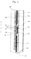
- eine schematische Draufsicht der erfindungsgemäßen Dichtungsanordnung;
- Fig. 4
- einen Schnitt längs der Linie II-II in
Fig. 1 , der die erfindungsgemäße Dichtungsanordnung in einer alternativen Ausgestaltung zeigt. -
Fig. 1 zeigt eine perspektivische Ansicht eines Kraftfahrzeugs 100, das eine Tür 130 und eine Karosserie 110 aufweist. Die Tür 130 ist mit einer Dichtungsanordnung 50 versehen, die die Tür 130 gegenüber der Karosserie 110 abdichtet. - Wie insbesondere die
Fig. 2 und4 zu erkennen geben, weist die erfindungsgemäße Dichtungsanordnung 50 einen ersten Dichtungsabschnitt 20, einen zweiten Dichtungsabschnitt 40 und einen Befestigungsabschnitt 30 auf. Das Kraftfahrzeug 100 weist einen Flansch 120 auf, der aus einem inneren Rahmenteil 123 und einem äußeren Rahmenteil 124 zusammengesetzt ist. Der Flansch 120 ist in Längsrichtung L in Fixierungsbereiche 122, die eine Öffnung 125 aufweisen, und in Stützbereiche 121 unterteilt. Der Befestigungsabschnitt 30 ist in Stützabschnitte 31 und Fixierungsabschnitte 32 unterteilt. Die inFig. 2 und4 wiedergegebenen Querschnitte der erfindungsgemäßen Dichtungsanordnung 50, die quer zur Längsrichtung L verlaufen, zeigen einen Schnitt entlang eines Fixierungsabschnittes 32 der Dichtungsanordnung 50. Entlang des Fixierungsabschnitts 32 ist der Befestigungsabschnitt 30 zwischen dem inneren Rahmenteil 123 und dem äußeren Rahmenteil 124 des Flansches 120 angeordnet. So verläuft das äußere Rahmenteil 124 entlang der Außenseite 36 des Befestigungsabschnitts 30, und das innere Rahmenteil 123 verläuft entlang einer Innenseite 35 des Befestigungsabschnitts 30. - Der Dichtungsabschnitt 20 weist eine Hohlkammer 21 auf, die die Tür 130 gegenüber der Karosserie 110 des Kraftfahrzeugs 100 abdichtet. Der Dichtungsabschnitt 20 liegt außenseitig an dem äußeren Rahmenteil 124 an. Das äußere Rahmenteil 124 ist in der Ausnehmung 11 aufgenommen, die zwischen Befestigungsabschnitt 30 und Dichtungsabschnitt 20 angeordnet ist. Der Randbereich 126 des äußeren Rahmenteils 124 ragt im Fixierungsbereich 122 von dem inneren Rahmenteil 123 weg.
- Der Dichtungsabschnitt 40 weist zwei Dichtlippen 41 auf, die dafür geeignet sind, an einer Fahrzeugverkleidung anzuliegen und den Flansch 120 gegenüber den Blicken eines Fahrzeuginsassen zu kaschieren.
- Der in
Fig. 2 gezeigte Fixierungsabschnitt 32 des Befestigungsabschnitts 30 weist vier Haltelippen 34 auf, die das Herausziehen des Fixierungsabschnitts 32 aus dem Fixierungsbereich 122 erschweren. In der alternativen Ausgestaltung der Dichtungsanordnung 50, wie sie inFig. 4 gezeigt ist, weist der Fixierungsabschnitt 32 des Befestigungsabschnitts 30 der Dichtung 10 zwei Haltelippen 34 auf, die das freie Ende pfeilförmig ausbilden. - Wie aus der
Fig. 3 zu entnehmen ist, sind die Stützabschnitte 31 und die Fixierungsabschnitte 32 des Befestigungsabschnitts 30 in Längsrichtung L hintereinander angeordnet. Ebenso sind die Stützbereiche 121 und die Fixierungsbereiche 122 des Flansches 120 auch in Längsrichtung L hintereinander angeordnet. Weiterhin sind die Stützabschnitte 31 und die Fixierungsabschnitte 32 sowie die Stützbereiche 121 und die Fixierungsbereiche 122 alternierend angeordnet. - Die Stützabschnitte 31 und die Fixierungsabschnitte 32 sind jeweils durch einen Zwischenraum 33 voneinander getrennt. Die Stützbereiche 121 und die Fixierungsbereiche 122 sind durch ein inneres Rahmenteil 123 und ein äußeres Rahmenteil 124 gebildet, wobei das innere Rahmenteil 123 in Längsrichtung L geradlinig verläuft, und das äußere Rahmenteil 124 in Längsrichtung L spundwandförmig verläuft. Wie ebenfalls die
Fig. 3 zu erkennen gibt, ist der Fixierungsabschnitt 32 formschlüssig in der Öffnung 125 aufgenommen. Die Öffnung 125 ist vorzugsweise in der Form einer Tasche ausgebildet. - Das äußere Rahmenteil 124 verläuft im Stützbereich 121 auf der Innenseite 35 des Befestigungsabschnitts 30. Zwischen dem Stützbereich 121 und dem Fixierungsbereich 122 verläuft das äußere Rahmenteil 124 durch den Zwischenraum 33 hindurch. Im Fixierungsbereich 122 verläuft das äußere Rahmenteil 124 entlang der Außenseite 36 des Befestigungsabschnitts 30. Das innere Rahmenteil 123 verläuft sowohl am Stützbereich 121 als auch am Fixierungsbereich 122 entlang der Innenseite 35 des Befestigungsabschnitts 30.
- Die in den Ausführungsbeispielen wiedergegebene Dichtungsanordnung 50 bietet den Vorteil, dass auf einen Carrier oder eine Armierung der Dichtung verzichtet werden kann. Ebenso kann auf das Kleben durch Klebstoff oder durch ein Klebeband sowie auf das Anheften der Dichtung mittels Klammern oder Clipsen verzichtet werden. Dadurch können sowohl Gewicht als auch Kosten eingespart werden.
-
- 10
- Dichtung
- 11
- Ausnehmung
- 20
- Dichtungsabschnitt
- 21
- Hohlkammer
- 30
- Befestigungsabschnitt
- 31
- Stützabschnitt
- 32
- Fixierungsabschnitt
- 33
- Zwischenraum
- 34
- Haltelippe
- 35
- Innenseite
- 36
- Außenseite
- 40
- Dichtungsabschnitt
- 41
- Dichtlippe
- 50
- Dichtungsanordnung
- 100
- Kraftfahrzeug
- 110
- Karosserie
- 120
- Flansch
- 121
- Stützbereich
- 122
- Fixierungsbereich
- 123
- inneres Rahmenteil
- 124
- äußeres Rahmenteil
- 125
- Öffnung
- 126
- Randbereich
- 130
- Tür
Claims (17)
- Dichtung für ein Kraftfahrzeug (100), wobei die Dichtung (10) sich in einer Längsrichtung (L) erstreckt und an einem Flansch (120), der ein inneres Rahmenteil (123) und ein äußeres Rahmenteil (124) aufweist, befestigbar ist, umfassend:wenigstens einen Dichtungsabschnitt (20) undeinen Befestigungsabschnitt (30);wobei der Befestigungsabschnitt (30) wenigstens einen Stützabschnitt (31), der sich an einem Stützbereich (121) des Flansches (120) abstützt, und wenigstens einen Fixierungsabschnitt (32), der an einem Fixierungsbereich (122) des Flansches (120) befestigbar ist, aufweist undwobei der Stützabschnitt (31) und der Fixierungsabschnitt (32) in Längsrichtung (L) hintereinander angeordnet sind.
- Dichtung nach Anspruch 1, gekennzeichnet durch eine Vielzahl an Stützabschnitten (31) und Fixierungsabschnitten (32), die in Längsrichtung (L) alternierend angeordnet sind.
- Dichtung nach Anspruch 1 oder 2, dadurch gekennzeichnet, dass der Fixierungsbereich (122) eine Öffnung (125) aufweist, die durch das innere Rahmenteil (123) und das äußere Rahmenteil (124) gebildet ist, wobei vorzugsweise der Fixierungsabschnitt (32) in dem Fixierungsbereich (122) aufgenommen, weiterhin vorzugsweise formschlüssig aufgenommen ist.
- Dichtung nach einem der Ansprüche 1 bis 3, dadurch gekennzeichnet, dass die Stützabschnitte (31) und/oder die Fixierungsabschnitte (32) in Längsrichtung (L) durch einen Zwischenraum (33) voneinander getrennt sind.
- Dichtung nach einem der Ansprüche 1 bis 4, gekennzeichnet durch einen ersten Dichtungsabschnitt (20), der wenigstens eine Hohlkammer (21) aufweist und der geeignet ist, die Karosserie (110) gegenüber einer Tür (130) abzudichten.
- Dichtung nach einem der Ansprüche 1 bis 5, gekennzeichnet durch einen zweiten Dichtungsabschnitt (40), der wenigstens eine Dichtlippe (41) aufweist und vorzugsweise zum Abdichten der Karosserie (110) gegenüber einer Fahrzeuginnenverkleidung (140) dient.
- Dichtung nach einem der Ansprüche 1 bis 6, gekennzeichnet durch eine Ausnehmung (11), die abschnittsweise zur Aufnahme des inneren Rahmenteils (123) oder des äußeren Rahmenteils (124) dient und zwischen Befestigungsabschnitt (30) und Dichtungsabschnitt (20) angeordnet ist.
- Dichtung nach einem der Ansprüche 3 bis 7, dadurch gekennzeichnet, dass der Fixierungsabschnitt (32) wenigstens eine Haltelippe (34) aufweist, die dafür geeignet ist den Fixierungsabschnitt (32) in der Öffnung (125) zu halten.
- Dichtung nach einem der Ansprüche 1 bis 8, dadurch gekennzeichnet, dass der Fixierungsabschnitt (32) und der Stützabschnitt (31) in Längsrichtung (L) einen annähernd gleichbleibenden Querschnitt aufweisen.
- Dichtungsanordnung für ein Kraftfahrzeug (100), insbesondere zum Abdichten einer Karosserie (110), umfassend:eine sich in Längsrichtung (L) erstreckende Dichtung (10) nach einem der Ansprüche 1 bis 9 undeinen Flansch (120) mit einem inneren Rahmenteil (123) und einem äußeren Rahmenteil (124);wobei der Flansch (120) wenigstens einen Stützbereich (121) zur Aufnahme des Stützabschnitts (31) und wenigstens einen Fixierungsbereich (122) zur Aufnahme des Fixierungsabschnitts (32) aufweist undwobei der Stützbereich (121) und der Fixierungsbereich (122) in Längsrichtung (L) hintereinander angeordnet sind.
- Dichtungsanordnung nach Anspruch 10, gekennzeichnet durch eine Vielzahl an Stützbereichen (121) und Fixierungsbereichen (122), die in Längsrichtung (L) alternierend angeordnet sind.
- Dichtungsanordnung nach Anspruch 10 oder 11, dadurch gekennzeichnet, dass der Fixierungsbereich (122) eine Öffnung (125) aufweist, die durch das innere Rahmenteil (123) und das äußere Rahmenteil (124) gebildet ist, wobei vorzugsweise der Fixierungsabschnitt (32) in dem Fixierungsbereich (122) aufgenommen, weiterhin vorzugsweise formschlüssig aufgenommen ist.
- Dichtungsanordnung nach einem der Ansprüche 10 bis 12, dadurch gekennzeichnet, dass der Befestigungsabschnitt (30) eine Innenseite (35) und eine Außenseite (36) aufweist, wobei entlang des Stützbereichs (121) das innere Rahmenteil (123) und das äußere Rahmenteil (124) an der Innenseite (35) verlaufen, und vorzugsweise entlang des Fixierungsbereichs (122) das innere Rahmenteil (123) an der Innenseite (35) und das äußere Rahmenteil (124) an der Außenseite (36) verläuft.
- Dichtungsanordnung nach einem der Ansprüche 10 bis 13, dadurch gekennzeichnet, dass das äußere Rahmenteil (124) wenigstens durch einen Zwischenraum (33) hindurch verläuft, der die Stützabschnitte (31) und/oder Fixierungsabschnitte (32) in Längsrichtung (L) voneinander trennt.
- Dichtungsanordnung nach einem der Ansprüche 10 bis 14, dadurch gekennzeichnet, dass das innere Rahmenteil (123) in Längsrichtung (L) im Wesentlichen geradlinig verläuft und vorzugsweise das äußere Rahmenteil (124) in Längsrichtung (L) im Wesentlichen spundwandförmig verläuft.
- Dichtungsanordnung nach einem der Ansprüche 10 bis 15, dadurch gekennzeichnet, dass das innere Rahmenteil (123) und das äußere Rahmenteil (124) abschnittsweise parallel zueinander in Längsrichtung (L) verlaufen.
- Dichtungsanordnung nach einem der Ansprüche 10 bis 16, dadurch gekennzeichnet, dass das äußere Rahmenteil (124) einen Randbereich (126) aufweist, der zumindest im Fixierungsbereich (122) vom inneren Rahmenteil (123) wegragt und vorzugsweise in der Ausnehmung (11) aufgenommen ist.
Priority Applications (3)
| Application Number | Priority Date | Filing Date | Title |
|---|---|---|---|
| PL11179085T PL2423023T3 (pl) | 2010-08-27 | 2011-08-26 | Uszczelka i układ uszczelniający dla pojazdu mechanicznego, zwłaszcza do uszczelnienia nadwozia |
| SI201130424T SI2423023T1 (sl) | 2010-08-27 | 2011-08-26 | Tesnilo in tesnilni sklop za motorno vozilo, zlasti za zatesnitev karoserije |
| HRP20150303AT HRP20150303T1 (hr) | 2010-08-27 | 2015-03-18 | Brtva i sklop brtvi za motorna vozila, posebno za brtvljenje karoserije |
Applications Claiming Priority (1)
| Application Number | Priority Date | Filing Date | Title |
|---|---|---|---|
| DE102010035588A DE102010035588B4 (de) | 2010-08-27 | 2010-08-27 | Dichtung und Dichtungsanordnung für ein Kraftfahrzeug, insbesondere zum Abdichten einer Karosserie |
Publications (3)
| Publication Number | Publication Date |
|---|---|
| EP2423023A2 true EP2423023A2 (de) | 2012-02-29 |
| EP2423023A3 EP2423023A3 (de) | 2012-07-18 |
| EP2423023B1 EP2423023B1 (de) | 2015-01-14 |
Family
ID=44532681
Family Applications (1)
| Application Number | Title | Priority Date | Filing Date |
|---|---|---|---|
| EP11179085.3A Active EP2423023B1 (de) | 2010-08-27 | 2011-08-26 | Dichtung und Dichtungsanordnung für ein Kraftfahrzeug, insbesondere zum Abdichten einer Karosserie |
Country Status (8)
| Country | Link |
|---|---|
| EP (1) | EP2423023B1 (de) |
| DE (1) | DE102010035588B4 (de) |
| ES (1) | ES2534656T3 (de) |
| HR (1) | HRP20150303T1 (de) |
| PL (1) | PL2423023T3 (de) |
| PT (1) | PT2423023E (de) |
| RS (1) | RS53838B1 (de) |
| SI (1) | SI2423023T1 (de) |
Citations (3)
| Publication number | Priority date | Publication date | Assignee | Title |
|---|---|---|---|---|
| DE10047818A1 (de) | 2000-09-27 | 2002-04-18 | Volkswagen Ag | Befestigungsanordnung für eine Kraftfahrzeug-Innenverkleidung |
| DE102006060391A1 (de) | 2006-12-20 | 2008-06-26 | Metzeler Automotive Profile Systems Gmbh | Dichtungsanordnung zum Abdichten der Karosserie eines Kraftfahrzeugs |
| DE102009008106B3 (de) | 2008-12-12 | 2010-04-29 | Metzeler Automotive Profile Systems Gmbh | Dichtung für ein Kraftfahrzeug mit einem Fixierungselement und ein solches Fixierungselement |
Family Cites Families (2)
| Publication number | Priority date | Publication date | Assignee | Title |
|---|---|---|---|---|
| FR2806971B1 (fr) * | 2000-03-30 | 2002-11-08 | Hutchinson | Joint d'etancheite, en particulier joint formant lecheur pour vitre coulissante de vehicule automobile |
| FR2829173B1 (fr) * | 2001-08-30 | 2007-02-02 | Metzeler Automotive Profile | Joint double d'etancheite pour ouvrant, notamment pour porte de vehicule automobile, et son procede de fabrication |
-
2010
- 2010-08-27 DE DE102010035588A patent/DE102010035588B4/de active Active
-
2011
- 2011-08-26 EP EP11179085.3A patent/EP2423023B1/de active Active
- 2011-08-26 PT PT111790853T patent/PT2423023E/pt unknown
- 2011-08-26 RS RS20150097A patent/RS53838B1/sr unknown
- 2011-08-26 ES ES11179085.3T patent/ES2534656T3/es active Active
- 2011-08-26 SI SI201130424T patent/SI2423023T1/sl unknown
- 2011-08-26 PL PL11179085T patent/PL2423023T3/pl unknown
-
2015
- 2015-03-18 HR HRP20150303AT patent/HRP20150303T1/hr unknown
Patent Citations (3)
| Publication number | Priority date | Publication date | Assignee | Title |
|---|---|---|---|---|
| DE10047818A1 (de) | 2000-09-27 | 2002-04-18 | Volkswagen Ag | Befestigungsanordnung für eine Kraftfahrzeug-Innenverkleidung |
| DE102006060391A1 (de) | 2006-12-20 | 2008-06-26 | Metzeler Automotive Profile Systems Gmbh | Dichtungsanordnung zum Abdichten der Karosserie eines Kraftfahrzeugs |
| DE102009008106B3 (de) | 2008-12-12 | 2010-04-29 | Metzeler Automotive Profile Systems Gmbh | Dichtung für ein Kraftfahrzeug mit einem Fixierungselement und ein solches Fixierungselement |
Also Published As
| Publication number | Publication date |
|---|---|
| DE102010035588B4 (de) | 2012-05-31 |
| PT2423023E (pt) | 2015-04-30 |
| RS53838B1 (sr) | 2015-06-30 |
| EP2423023A3 (de) | 2012-07-18 |
| HRP20150303T1 (hr) | 2015-04-10 |
| SI2423023T1 (sl) | 2015-04-30 |
| ES2534656T3 (es) | 2015-04-27 |
| PL2423023T3 (pl) | 2015-06-30 |
| EP2423023B1 (de) | 2015-01-14 |
| DE102010035588A1 (de) | 2012-03-01 |
Similar Documents
| Publication | Publication Date | Title |
|---|---|---|
| DE3416480C2 (de) | Befestigungsvorrichtung für Fensterscheiben | |
| EP2475538B1 (de) | Fahrzeugtüranordnung und verfahren zur montage | |
| EP1131220B2 (de) | Fensterdichtungsprofil für ein kabriolett | |
| DE102008005282A1 (de) | Befestigungsanordnung eines Dachmoduls an einem Dachrahmen einer Kraftwagenkarosserie | |
| DE102010015403A1 (de) | Dachmodul für ein Kraftfahrzeug | |
| DE102014005721B3 (de) | Scheibenanordnung für ein Kraftfahrzeug | |
| DE102004018943A1 (de) | Blende zur Abdeckung eines Trägerelementes eines Kraftwagens | |
| DE202013103871U1 (de) | Abdichtungsprofil zum Anschluss eines Anbauteils an eine Scheibe, sowie Abdichtungsanordnung | |
| DE102014118029A1 (de) | Profilstrang und verfahren zum herstellen eines profilstrangs | |
| EP2423023B1 (de) | Dichtung und Dichtungsanordnung für ein Kraftfahrzeug, insbesondere zum Abdichten einer Karosserie | |
| DE19531600B4 (de) | Dichtung für eine verlagerbare Fensterscheibe eines Fahrzeugs | |
| EP2054252B1 (de) | Kraftfahrzeug mit hinteren seitenscheiben | |
| EP2230116A2 (de) | Innenverkleidung für ein Faltverdeck | |
| EP3024679B1 (de) | Abdichtungsprofil zum anschluss eines anbauteils an eine scheibe, sowie abdichtungsanordnung | |
| DE102014016194B4 (de) | Türeinstieg für ein Fahrzeug | |
| DE102015210511A1 (de) | Innenverkleidung für ein Kraftfahrzeug | |
| WO2019011783A1 (de) | Halter für ein flächenelement einer sonnenschutz- oder verdunklungsvorrichtung und sonnenschutz- oder verdunklungsvorrichtung | |
| DE3424579A1 (de) | Dichtung, insbesondere fuer eine rahmenlos gefuehrte seitenscheibe eines fahrzeuges | |
| DE102016218676A1 (de) | Kraftfahrzeug | |
| DE102016114657A1 (de) | Dichtungsprofil für ein Kraftfahrzeug oder Kraftfahrzeugbauteil sowie Verfahren zur Befestigung eines Dichtungsprofils | |
| DE10202308B4 (de) | Vorgefertigtes Fahrzeugdachmodul | |
| DE102015218405A1 (de) | Verbundbauteil zur Führung und Abdichtung von Strukturelementen im Bereich einer Fahrzeugtür | |
| DE10247229B4 (de) | Dichtungsanordnung, insbesondere zum Abdichten der Windschutzscheibe eines Kraftfahrzeugs | |
| DE102005031729A1 (de) | Fahrzeugtür für ein Kraftfahrzeug | |
| DE102015010336A1 (de) | Wasserableiteinrichtung für eine Frontscheibe eines Kraftwagens und Kraftwagen |
Legal Events
| Date | Code | Title | Description |
|---|---|---|---|
| AK | Designated contracting states |
Kind code of ref document: A2 Designated state(s): AL AT BE BG CH CY CZ DE DK EE ES FI FR GB GR HR HU IE IS IT LI LT LU LV MC MK MT NL NO PL PT RO RS SE SI SK SM TR |
|
| AX | Request for extension of the european patent |
Extension state: BA ME |
|
| PUAI | Public reference made under article 153(3) epc to a published international application that has entered the european phase |
Free format text: ORIGINAL CODE: 0009012 |
|
| PUAL | Search report despatched |
Free format text: ORIGINAL CODE: 0009013 |
|
| AK | Designated contracting states |
Kind code of ref document: A3 Designated state(s): AL AT BE BG CH CY CZ DE DK EE ES FI FR GB GR HR HU IE IS IT LI LT LU LV MC MK MT NL NO PL PT RO RS SE SI SK SM TR |
|
| AX | Request for extension of the european patent |
Extension state: BA ME |
|
| RIC1 | Information provided on ipc code assigned before grant |
Ipc: B60J 10/08 20060101ALI20120611BHEP Ipc: B60J 10/00 20060101AFI20120611BHEP |
|
| 17P | Request for examination filed |
Effective date: 20120823 |
|
| 17Q | First examination report despatched |
Effective date: 20121114 |
|
| RAP1 | Party data changed (applicant data changed or rights of an application transferred) |
Owner name: COOPER STANDARD GMBH |
|
| GRAP | Despatch of communication of intention to grant a patent |
Free format text: ORIGINAL CODE: EPIDOSNIGR1 |
|
| INTG | Intention to grant announced |
Effective date: 20140728 |
|
| GRAP | Despatch of communication of intention to grant a patent |
Free format text: ORIGINAL CODE: EPIDOSNIGR1 |
|
| GRAS | Grant fee paid |
Free format text: ORIGINAL CODE: EPIDOSNIGR3 |
|
| GRAA | (expected) grant |
Free format text: ORIGINAL CODE: 0009210 |
|
| INTG | Intention to grant announced |
Effective date: 20141124 |
|
| AK | Designated contracting states |
Kind code of ref document: B1 Designated state(s): AL AT BE BG CH CY CZ DE DK EE ES FI FR GB GR HR HU IE IS IT LI LT LU LV MC MK MT NL NO PL PT RO RS SE SI SK SM TR |
|
| REG | Reference to a national code |
Ref country code: GB Ref legal event code: FG4D Free format text: NOT ENGLISH |
|
| REG | Reference to a national code |
Ref country code: CH Ref legal event code: EP |
|
| REG | Reference to a national code |
Ref country code: IE Ref legal event code: FG4D Free format text: LANGUAGE OF EP DOCUMENT: GERMAN |
|
| REG | Reference to a national code |
Ref country code: AT Ref legal event code: REF Ref document number: 706830 Country of ref document: AT Kind code of ref document: T Effective date: 20150215 |
|
| REG | Reference to a national code |
Ref country code: DE Ref legal event code: R096 Ref document number: 502011005633 Country of ref document: DE Effective date: 20150226 |
|
| REG | Reference to a national code |
Ref country code: HR Ref legal event code: TUEP Ref document number: P20150303 Country of ref document: HR |
|
| REG | Reference to a national code |
Ref country code: RO Ref legal event code: EPE |
|
| REG | Reference to a national code |
Ref country code: HR Ref legal event code: T1PR Ref document number: P20150303 Country of ref document: HR |
|
| REG | Reference to a national code |
Ref country code: SE Ref legal event code: TRGR |
|
| REG | Reference to a national code |
Ref country code: ES Ref legal event code: FG2A Ref document number: 2534656 Country of ref document: ES Kind code of ref document: T3 Effective date: 20150427 |
|
| REG | Reference to a national code |
Ref country code: PT Ref legal event code: SC4A Free format text: AVAILABILITY OF NATIONAL TRANSLATION Effective date: 20150409 |
|
| REG | Reference to a national code |
Ref country code: NL Ref legal event code: VDEP Effective date: 20150114 |
|
| REG | Reference to a national code |
Ref country code: GR Ref legal event code: EP Ref document number: 20150400654 Country of ref document: GR Effective date: 20150421 |
|
| REG | Reference to a national code |
Ref country code: LT Ref legal event code: MG4D |
|
| REG | Reference to a national code |
Ref country code: PL Ref legal event code: T3 |
|
| REG | Reference to a national code |
Ref country code: SK Ref legal event code: T3 Ref document number: E 18467 Country of ref document: SK |
|
| PG25 | Lapsed in a contracting state [announced via postgrant information from national office to epo] |
Ref country code: FI Free format text: LAPSE BECAUSE OF FAILURE TO SUBMIT A TRANSLATION OF THE DESCRIPTION OR TO PAY THE FEE WITHIN THE PRESCRIBED TIME-LIMIT Effective date: 20150114 Ref country code: NO Free format text: LAPSE BECAUSE OF FAILURE TO SUBMIT A TRANSLATION OF THE DESCRIPTION OR TO PAY THE FEE WITHIN THE PRESCRIBED TIME-LIMIT Effective date: 20150414 Ref country code: LT Free format text: LAPSE BECAUSE OF FAILURE TO SUBMIT A TRANSLATION OF THE DESCRIPTION OR TO PAY THE FEE WITHIN THE PRESCRIBED TIME-LIMIT Effective date: 20150114 |
|
| REG | Reference to a national code |
Ref country code: FR Ref legal event code: PLFP Year of fee payment: 5 |
|
| PG25 | Lapsed in a contracting state [announced via postgrant information from national office to epo] |
Ref country code: NL Free format text: LAPSE BECAUSE OF FAILURE TO SUBMIT A TRANSLATION OF THE DESCRIPTION OR TO PAY THE FEE WITHIN THE PRESCRIBED TIME-LIMIT Effective date: 20150114 Ref country code: LV Free format text: LAPSE BECAUSE OF FAILURE TO SUBMIT A TRANSLATION OF THE DESCRIPTION OR TO PAY THE FEE WITHIN THE PRESCRIBED TIME-LIMIT Effective date: 20150114 Ref country code: IS Free format text: LAPSE BECAUSE OF FAILURE TO SUBMIT A TRANSLATION OF THE DESCRIPTION OR TO PAY THE FEE WITHIN THE PRESCRIBED TIME-LIMIT Effective date: 20150514 |
|
| REG | Reference to a national code |
Ref country code: DE Ref legal event code: R097 Ref document number: 502011005633 Country of ref document: DE |
|
| PG25 | Lapsed in a contracting state [announced via postgrant information from national office to epo] |
Ref country code: DK Free format text: LAPSE BECAUSE OF FAILURE TO SUBMIT A TRANSLATION OF THE DESCRIPTION OR TO PAY THE FEE WITHIN THE PRESCRIBED TIME-LIMIT Effective date: 20150114 Ref country code: EE Free format text: LAPSE BECAUSE OF FAILURE TO SUBMIT A TRANSLATION OF THE DESCRIPTION OR TO PAY THE FEE WITHIN THE PRESCRIBED TIME-LIMIT Effective date: 20150114 |
|
| PLBE | No opposition filed within time limit |
Free format text: ORIGINAL CODE: 0009261 |
|
| STAA | Information on the status of an ep patent application or granted ep patent |
Free format text: STATUS: NO OPPOSITION FILED WITHIN TIME LIMIT |
|
| REG | Reference to a national code |
Ref country code: HU Ref legal event code: AG4A Ref document number: E024679 Country of ref document: HU |
|
| 26N | No opposition filed |
Effective date: 20151015 |
|
| PG25 | Lapsed in a contracting state [announced via postgrant information from national office to epo] |
Ref country code: LU Free format text: LAPSE BECAUSE OF FAILURE TO SUBMIT A TRANSLATION OF THE DESCRIPTION OR TO PAY THE FEE WITHIN THE PRESCRIBED TIME-LIMIT Effective date: 20150826 Ref country code: MC Free format text: LAPSE BECAUSE OF FAILURE TO SUBMIT A TRANSLATION OF THE DESCRIPTION OR TO PAY THE FEE WITHIN THE PRESCRIBED TIME-LIMIT Effective date: 20150114 |
|
| REG | Reference to a national code |
Ref country code: CH Ref legal event code: PL |
|
| PG25 | Lapsed in a contracting state [announced via postgrant information from national office to epo] |
Ref country code: CH Free format text: LAPSE BECAUSE OF NON-PAYMENT OF DUE FEES Effective date: 20150831 Ref country code: LI Free format text: LAPSE BECAUSE OF NON-PAYMENT OF DUE FEES Effective date: 20150831 |
|
| REG | Reference to a national code |
Ref country code: IE Ref legal event code: MM4A |
|
| PG25 | Lapsed in a contracting state [announced via postgrant information from national office to epo] |
Ref country code: IE Free format text: LAPSE BECAUSE OF NON-PAYMENT OF DUE FEES Effective date: 20150826 |
|
| REG | Reference to a national code |
Ref country code: HR Ref legal event code: ODRP Ref document number: P20150303 Country of ref document: HR Payment date: 20160812 Year of fee payment: 6 |
|
| REG | Reference to a national code |
Ref country code: FR Ref legal event code: PLFP Year of fee payment: 6 |
|
| PGFP | Annual fee paid to national office [announced via postgrant information from national office to epo] |
Ref country code: BG Payment date: 20160822 Year of fee payment: 6 Ref country code: GB Payment date: 20160824 Year of fee payment: 6 Ref country code: IT Payment date: 20160823 Year of fee payment: 6 |
|
| PGFP | Annual fee paid to national office [announced via postgrant information from national office to epo] |
Ref country code: CZ Payment date: 20160815 Year of fee payment: 6 Ref country code: SE Payment date: 20160823 Year of fee payment: 6 Ref country code: FR Payment date: 20160825 Year of fee payment: 6 Ref country code: AL Payment date: 20160819 Year of fee payment: 6 Ref country code: PT Payment date: 20160824 Year of fee payment: 6 Ref country code: RS Payment date: 20160818 Year of fee payment: 6 Ref country code: SI Payment date: 20160818 Year of fee payment: 6 Ref country code: GR Payment date: 20160822 Year of fee payment: 6 Ref country code: HU Payment date: 20160815 Year of fee payment: 6 Ref country code: PL Payment date: 20160816 Year of fee payment: 6 Ref country code: RO Payment date: 20160823 Year of fee payment: 6 Ref country code: SK Payment date: 20160815 Year of fee payment: 6 |
|
| PGFP | Annual fee paid to national office [announced via postgrant information from national office to epo] |
Ref country code: ES Payment date: 20160829 Year of fee payment: 6 Ref country code: HR Payment date: 20160812 Year of fee payment: 6 Ref country code: TR Payment date: 20160815 Year of fee payment: 6 |
|
| PG25 | Lapsed in a contracting state [announced via postgrant information from national office to epo] |
Ref country code: MT Free format text: LAPSE BECAUSE OF FAILURE TO SUBMIT A TRANSLATION OF THE DESCRIPTION OR TO PAY THE FEE WITHIN THE PRESCRIBED TIME-LIMIT Effective date: 20150114 |
|
| PG25 | Lapsed in a contracting state [announced via postgrant information from national office to epo] |
Ref country code: SM Free format text: LAPSE BECAUSE OF FAILURE TO SUBMIT A TRANSLATION OF THE DESCRIPTION OR TO PAY THE FEE WITHIN THE PRESCRIBED TIME-LIMIT Effective date: 20150114 |
|
| PG25 | Lapsed in a contracting state [announced via postgrant information from national office to epo] |
Ref country code: CY Free format text: LAPSE BECAUSE OF FAILURE TO SUBMIT A TRANSLATION OF THE DESCRIPTION OR TO PAY THE FEE WITHIN THE PRESCRIBED TIME-LIMIT Effective date: 20150114 |
|
| PG25 | Lapsed in a contracting state [announced via postgrant information from national office to epo] |
Ref country code: BE Free format text: LAPSE BECAUSE OF NON-PAYMENT OF DUE FEES Effective date: 20150831 |
|
| REG | Reference to a national code |
Ref country code: AT Ref legal event code: MM01 Ref document number: 706830 Country of ref document: AT Kind code of ref document: T Effective date: 20160826 |
|
| PG25 | Lapsed in a contracting state [announced via postgrant information from national office to epo] |
Ref country code: AT Free format text: LAPSE BECAUSE OF NON-PAYMENT OF DUE FEES Effective date: 20160826 |
|
| REG | Reference to a national code |
Ref country code: HR Ref legal event code: PBON Ref document number: P20150303 Country of ref document: HR Effective date: 20170826 |
|
| GBPC | Gb: european patent ceased through non-payment of renewal fee |
Effective date: 20170826 |
|
| PG25 | Lapsed in a contracting state [announced via postgrant information from national office to epo] |
Ref country code: RO Free format text: LAPSE BECAUSE OF NON-PAYMENT OF DUE FEES Effective date: 20170826 Ref country code: HU Free format text: LAPSE BECAUSE OF NON-PAYMENT OF DUE FEES Effective date: 20170827 Ref country code: SE Free format text: LAPSE BECAUSE OF NON-PAYMENT OF DUE FEES Effective date: 20170827 Ref country code: CZ Free format text: LAPSE BECAUSE OF NON-PAYMENT OF DUE FEES Effective date: 20170826 |
|
| REG | Reference to a national code |
Ref country code: SK Ref legal event code: MM4A Ref document number: E 18467 Country of ref document: SK Effective date: 20170826 |
|
| REG | Reference to a national code |
Ref country code: FR Ref legal event code: ST Effective date: 20180430 |
|
| PG25 | Lapsed in a contracting state [announced via postgrant information from national office to epo] |
Ref country code: PT Free format text: LAPSE BECAUSE OF NON-PAYMENT OF DUE FEES Effective date: 20180226 Ref country code: RS Free format text: LAPSE BECAUSE OF NON-PAYMENT OF DUE FEES Effective date: 20180306 Ref country code: GR Free format text: LAPSE BECAUSE OF NON-PAYMENT OF DUE FEES Effective date: 20180305 Ref country code: SK Free format text: LAPSE BECAUSE OF NON-PAYMENT OF DUE FEES Effective date: 20170826 Ref country code: HR Free format text: LAPSE BECAUSE OF NON-PAYMENT OF DUE FEES Effective date: 20170826 Ref country code: SI Free format text: LAPSE BECAUSE OF NON-PAYMENT OF DUE FEES Effective date: 20170827 |
|
| REG | Reference to a national code |
Ref country code: SI Ref legal event code: KO00 Effective date: 20180410 |
|
| PGFP | Annual fee paid to national office [announced via postgrant information from national office to epo] |
Ref country code: MK Payment date: 20160822 Year of fee payment: 6 |
|
| PG25 | Lapsed in a contracting state [announced via postgrant information from national office to epo] |
Ref country code: GB Free format text: LAPSE BECAUSE OF NON-PAYMENT OF DUE FEES Effective date: 20170826 |
|
| PG25 | Lapsed in a contracting state [announced via postgrant information from national office to epo] |
Ref country code: IT Free format text: LAPSE BECAUSE OF NON-PAYMENT OF DUE FEES Effective date: 20170826 Ref country code: FR Free format text: LAPSE BECAUSE OF NON-PAYMENT OF DUE FEES Effective date: 20170831 |
|
| REG | Reference to a national code |
Ref country code: ES Ref legal event code: FD2A Effective date: 20181024 |
|
| PG25 | Lapsed in a contracting state [announced via postgrant information from national office to epo] |
Ref country code: BG Free format text: LAPSE BECAUSE OF NON-PAYMENT OF DUE FEES Effective date: 20180306 |
|
| PG25 | Lapsed in a contracting state [announced via postgrant information from national office to epo] |
Ref country code: AL Free format text: LAPSE BECAUSE OF NON-PAYMENT OF DUE FEES Effective date: 20170826 Ref country code: ES Free format text: LAPSE BECAUSE OF NON-PAYMENT OF DUE FEES Effective date: 20170827 |
|
| PG25 | Lapsed in a contracting state [announced via postgrant information from national office to epo] |
Ref country code: PL Free format text: LAPSE BECAUSE OF NON-PAYMENT OF DUE FEES Effective date: 20170826 |
|
| PG25 | Lapsed in a contracting state [announced via postgrant information from national office to epo] |
Ref country code: TR Free format text: LAPSE BECAUSE OF NON-PAYMENT OF DUE FEES Effective date: 20170826 |
|
| PGFP | Annual fee paid to national office [announced via postgrant information from national office to epo] |
Ref country code: DE Payment date: 20250910 Year of fee payment: 15 |