EP2422972B2 - Schwenkbare Inspektionsvorrichtung - Google Patents
Schwenkbare Inspektionsvorrichtung Download PDFInfo
- Publication number
- EP2422972B2 EP2422972B2 EP11173908.2A EP11173908A EP2422972B2 EP 2422972 B2 EP2422972 B2 EP 2422972B2 EP 11173908 A EP11173908 A EP 11173908A EP 2422972 B2 EP2422972 B2 EP 2422972B2
- Authority
- EP
- European Patent Office
- Prior art keywords
- housing
- control system
- folding
- light source
- camera
- Prior art date
- Legal status (The legal status is an assumption and is not a legal conclusion. Google has not performed a legal analysis and makes no representation as to the accuracy of the status listed.)
- Active
Links
- 238000007689 inspection Methods 0.000 title claims description 30
- 239000000463 material Substances 0.000 claims description 14
- 238000004026 adhesive bonding Methods 0.000 claims description 7
- 239000000123 paper Substances 0.000 claims description 3
- 239000000853 adhesive Substances 0.000 description 8
- 230000001070 adhesive effect Effects 0.000 description 8
- 238000004519 manufacturing process Methods 0.000 description 6
- 238000005286 illumination Methods 0.000 description 5
- 239000003973 paint Substances 0.000 description 5
- 238000003825 pressing Methods 0.000 description 5
- 238000007664 blowing Methods 0.000 description 3
- 230000007547 defect Effects 0.000 description 3
- 239000003292 glue Substances 0.000 description 3
- 238000005520 cutting process Methods 0.000 description 2
- 230000001419 dependent effect Effects 0.000 description 2
- 239000000428 dust Substances 0.000 description 2
- 238000004080 punching Methods 0.000 description 2
- 229920001817 Agar Polymers 0.000 description 1
- 206010039737 Scratch Diseases 0.000 description 1
- 230000006978 adaptation Effects 0.000 description 1
- 239000002131 composite material Substances 0.000 description 1
- 238000010276 construction Methods 0.000 description 1
- 239000002537 cosmetic Substances 0.000 description 1
- 230000002950 deficient Effects 0.000 description 1
- 238000004049 embossing Methods 0.000 description 1
- 239000000835 fiber Substances 0.000 description 1
- 239000011888 foil Substances 0.000 description 1
- 239000011159 matrix material Substances 0.000 description 1
- 238000012544 monitoring process Methods 0.000 description 1
- 239000005304 optical glass Substances 0.000 description 1
- 239000002245 particle Substances 0.000 description 1
- 230000000284 resting effect Effects 0.000 description 1
- 238000011144 upstream manufacturing Methods 0.000 description 1
- 238000009423 ventilation Methods 0.000 description 1
- 239000002699 waste material Substances 0.000 description 1
Images



Classifications
-
- B—PERFORMING OPERATIONS; TRANSPORTING
- B31—MAKING ARTICLES OF PAPER, CARDBOARD OR MATERIAL WORKED IN A MANNER ANALOGOUS TO PAPER; WORKING PAPER, CARDBOARD OR MATERIAL WORKED IN A MANNER ANALOGOUS TO PAPER
- B31B—MAKING CONTAINERS OF PAPER, CARDBOARD OR MATERIAL WORKED IN A MANNER ANALOGOUS TO PAPER
- B31B50/00—Making rigid or semi-rigid containers, e.g. boxes or cartons
-
- B—PERFORMING OPERATIONS; TRANSPORTING
- B31—MAKING ARTICLES OF PAPER, CARDBOARD OR MATERIAL WORKED IN A MANNER ANALOGOUS TO PAPER; WORKING PAPER, CARDBOARD OR MATERIAL WORKED IN A MANNER ANALOGOUS TO PAPER
- B31B—MAKING CONTAINERS OF PAPER, CARDBOARD OR MATERIAL WORKED IN A MANNER ANALOGOUS TO PAPER
- B31B50/00—Making rigid or semi-rigid containers, e.g. boxes or cartons
- B31B50/006—Controlling; Regulating; Measuring; Improving safety
-
- B—PERFORMING OPERATIONS; TRANSPORTING
- B65—CONVEYING; PACKING; STORING; HANDLING THIN OR FILAMENTARY MATERIAL
- B65H—HANDLING THIN OR FILAMENTARY MATERIAL, e.g. SHEETS, WEBS, CABLES
- B65H2301/00—Handling processes for sheets or webs
- B65H2301/50—Auxiliary process performed during handling process
- B65H2301/54—Auxiliary process performed during handling process for managing processing of handled material
- B65H2301/542—Quality control
-
- B—PERFORMING OPERATIONS; TRANSPORTING
- B65—CONVEYING; PACKING; STORING; HANDLING THIN OR FILAMENTARY MATERIAL
- B65H—HANDLING THIN OR FILAMENTARY MATERIAL, e.g. SHEETS, WEBS, CABLES
- B65H2404/00—Parts for transporting or guiding the handled material
- B65H2404/20—Belts
- B65H2404/25—Driving or guiding arrangements
- B65H2404/254—Arrangement for varying the guiding or transport length
-
- B—PERFORMING OPERATIONS; TRANSPORTING
- B65—CONVEYING; PACKING; STORING; HANDLING THIN OR FILAMENTARY MATERIAL
- B65H—HANDLING THIN OR FILAMENTARY MATERIAL, e.g. SHEETS, WEBS, CABLES
- B65H2404/00—Parts for transporting or guiding the handled material
- B65H2404/20—Belts
- B65H2404/26—Particular arrangement of belt, or belts
- B65H2404/261—Arrangement of belts, or belt(s) / roller(s) facing each other for forming a transport nip
- B65H2404/2613—Means for changing the transport path, e.g. deforming, lengthening
-
- B—PERFORMING OPERATIONS; TRANSPORTING
- B65—CONVEYING; PACKING; STORING; HANDLING THIN OR FILAMENTARY MATERIAL
- B65H—HANDLING THIN OR FILAMENTARY MATERIAL, e.g. SHEETS, WEBS, CABLES
- B65H2553/00—Sensing or detecting means
- B65H2553/40—Sensing or detecting means using optical, e.g. photographic, elements
- B65H2553/42—Cameras
Definitions
- the invention relates to an inspection device for flat, sheet-like material made of paper, cardboard or the like according to the preamble of claim 1.
- control systems comprising at least one line scan camera and a corresponding lighting device.
- the control device is arranged above and / or below the sheet transport plane.
- Different systems are known for transporting the sheets past the control system.
- transport systems which have two or more conveying means for transporting the sheets.
- transport systems are known which have at least one upper conveyor belt and at least one lower conveyor belt, between which the sheets are transported trapped.
- systems are known in which the sheets are transported by means of conveyor belts, which act together with a suction roll.
- Other transport systems which can not be enumerated here, are known and can be combined in a corresponding arrangement with control systems to control the lower and / or upper side of a sheet.
- the sheets are first printed wide web in a printing press. On the sheets, several benefits of the cartons to be produced are printed in each case, which are then punched out in a punch. The punched-out folding box blanks are then fed to a folding box gluing machine and processed here into folding boxes.
- the individual processing stations have conveying means driven for transporting the folding box blanks. These consist, for example, each one arranged on the side of the machine upper and lower conveyor belt, the lower conveyor belt is guided in a roller cheek and the upper conveyor belt in a roller rail.
- the conveyor belts are arranged transversely adjustable and can thus be adjusted to the respective folding carton blank format.
- the blanks are transported printed side down between the top and bottom conveyor belts. From the DE 10 2004 022 344 A1 Such a folding box gluing machine is known.
- the line scan camera Since the blanks are transported in the Faltschachtelklebemaschine with the printed side down from the transport device through the individual processing stations, the line scan camera must be located below the blank transport plane. Since the camera is to take a picture of the entire printed cut width, interfere with the lower continuous conveyor elements. From the DE 10 2005 050 040 A1 a device is known in which an inspection of a resting on a conveyor belt sheet on the back is possible. The camera is mounted in a gap of the conveyor belt below the sheet transport plane. For this purpose, the conveyor belt is placed over pulleys in a loop.
- the problem with controlling the sheets is the recognition of different errors. For example, color smudges are easier to see when the light source is oriented perpendicular to the object to be inspected instead of obliquely. If the light source illuminates the object vertically, the contrast increases and color smear can be better detected. On the other hand, for example, scratches on the sheets can be better recognized if the light source is arranged obliquely to the inspecting object, because the scratches can be better recognized by the oblique illumination due to other reflective properties of the surface. The angle of the camera to the object as well as the angle between the camera and the light source influence the control possibilities of the errors to be examined.
- a digital scanning device for decoding a digitally coded symbol comprising a light source having a plurality of individually controllable light elements for generating dark field illumination and additionally a bright field light source for providing bright field illumination.
- the control of the light sources via a controller depending on the decoding quality of the symbol.
- the solution shown is complex and not suitable for the processing of sheets with high transport speed.
- an inspection device for flat sheet material is known with a control system comprising a camera and a light source.
- the camera and the light source are mounted on a common holder and arranged transversely to the transport direction. In this way, the control device can be set to different blank formats.
- the device has a control system in the form of an optical glass fiber sensor. Transmitter and receiver are independently adjustable in motor with respect to the monitoring angle to the surface to be controlled.
- the inspection device has a control system, which consists of a camera, a light source and a housing. Arc-shaped material is passed by means of a transport device to the control system.
- the control system is arranged below the transport device.
- the camera angle with respect to the surface to be controlled of the sheet material and the angle of incidence of the rays of the light source on the sheet material via an adjustment of the camera and the light source or the transport device is changeable.
- the inspection device can be adapted in a simple manner to different inspection requirements, so that errors of different types are easier to detect.
- the light source is part of the housing.
- the housing can be pivoted via a pivoting device. This allows a particularly simple adjustment of the camera angle and the illumination angle.
- the control system is adjustably mounted transversely to the sheet or box transport direction.
- the camera is mounted with housing, for example, on two round guides and can be adjusted in a known manner by means of a spindle transverse to the transport direction of the sheet or cartons.
- several cameras can be arranged side by side and / or one behind the other in this way easily, whereby the inspection device can be adapted to different working widths and controls in a simple and cost-effective manner.
- the housing of the camera is connected to a blown air connection, via which an air flow is conducted into the housing, which exits at the upper gap of the housing, which is slit-shaped.
- the upper gap is formed either by the housing itself or from the composite of housing and light source by the upward air flow through the housing and the slot-shaped gap on the one hand, the sheet material, such as a box blank, pressed against the upper conveyor element, which significantly increases the smoothness of the carton blank in the area of the camera and thus makes the inspection possible even with high resolution.
- the inspection device has a transport device which has at least one upper and one lower conveying device with contacting conveying means.
- the lower conveyor is designed split and consists of at least two conveyors with a gap between these conveyors.
- the control system is placed in the gap between these lower conveyors.
- the upper conveyor can be carried out divided.
- the gap between the two lower conveyors is variable in their distance. This can be achieved for example via telescopic lower belt conveyors. Thus, the gap can be adapted to different camera or housing dimensions or angular positions.
- the inspection device is integrated into an already existing processing module.
- the print image control system can also be integrated in a separate inspection module, which is then installed between two existing processing modules within the machine assembly of Faltschachtelklebemaschine. This increases the flexibility with respect to the place of use.
- the inspection device can also be used as an off-line device, and thus be combined in an advantageous manner with the necessary for the specific application further modules such as feeder, discharge device and boom.
- a sorting device is useful for the discharge device when it comes to the sorting of various products.
- FIG. 1 shows by way of example individual processing stations a Faltschachtelklebemaschine.
- the folding box gluing machine begins in FIG. 1, bottom right, with an insert 1, which withdraws the blanks to be processed at high speed from a stack in succession and supplies them individually to the subsequent processing station. Following the insert 1 is followed by an alignment station 4, in which the blanks are individually aligned against a lateral stop.
- the alignment station is used to guide transversely positionable machine components in the form of two belt pairs, which serve as conveyor elements and can be transversely positioned via actuators.
- transversely positionable machine components in the form of belt pairs guide the conveying elements, which are positioned transversely with an actuator depending on the type of blank.
- the turning station 9 includes for rotating the blanks about a vertical axis by 90 ° two parallel juxtaposed conveyor lines whose speed is adjustable separately.
- the blanks are on both conveyor lines, so that they are rotated at different speeds of the two conveyor lines.
- the two conveyor lines contain driven rollers as conveying elements.
- a further alignment station 10 which corresponds in its construction of the alignment station behind the insert 1. It thus again contains transversely positionable machine components in the form of pairs of conveyor belts as conveying elements.
- the next processing station 13 serves to perform box-type dependent processing operations; For example, further score lines are pre-broken or special folds are performed. Also through the processing station 13 lead belt pairs as conveying elements that can be positioned transversely with actuators.
- a folding station 14 in which the blank parts previously provided with an adhesive seam are folded over by 180 °.
- the folding station 14 includes pairs of belts as conveying elements and an adhesive applicator, which can be moved by means of actuators in their dependent of the cutting type transverse position.
- a transfer station 15 from which the folded blanks, provided with not yet set adhesive seams, are exactly aligned in all parts with the subsequent collecting and pressing device 16.
- a shingled stream of folded blanks is first formed, which is subsequently held under pressure for some time between conveying press belts, so that the adhesive seams set.
- the transfer station also contains pairs of belts which can be transversely adjusted by means of actuators.
- FIG. 2 shows an example of a transport device 8, each with a left and right upper conveyor 3, 3 'and in each case a left and right lower conveyor 2.2', which is formed in the present example as a belt conveyor with corresponding conveyor belts as conveying means 5, 5 ', 12, 12'.
- the conveyors 3, 3 ', 2, 2' are mounted on round trusses 11, so that they can be adjusted to the respective box cutting width.
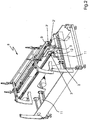
- FIG. 3 shows an inventive inspection device.
- the sheet-like material 24 to be checked such as folding box blanks, is transported by the conveying module 30 in the conveying direction 25 by means of a transport device 20.
- the transport device 20 has an upper conveyor 21 with an endless conveyor 23, which is guided around deflecting rollers, not shown.
- two lower conveyors 22, 22 ' which form a gap with the distance width b to each other.
- Both lower conveyors 22, 22 ' also have conveying means 23, which are guided around deflection rollers 26.
- the roller 27 is connected to a drive, not shown, and thus serves as a drive roller 27 for the conveyor 23 of the lower conveyor.
- the conveying means 23 in the present embodiment are designed as endless conveyor belts.
- the upper conveyor is mounted in a known manner in a roller rail 29 and the lower conveyor in non-illustrated roller cheeks.
- a control system 40 is mounted within the gap between the lower conveyors 22, 22 'such that the sheets transported across the gap can be tested from below by means of the control system 40.
- the control system 40 comprises a camera 41, a light source 42 and a housing 43, wherein the light source 42 may be disposed either inside or outside the housing 43, and as in the present example is also part of the housing 43.
- the housing 43 is provided with a blown air connection 44, via the blown air 45, which is guided, for example via a blower not shown in detail or even a side channel or roller compressor in the housing 43.
- the blown air flows around the camera and possibly the light source and exits from a gap 46 at the upper end of the housing 43, which is preferably slit-shaped, from, strikes the sheet-like material and presses it against the upper conveyor means 23.
- the smoothness of arcuate material in the control system positively influenced.
- the gap between the conveying devices 22, 2 'points in the FIG. 3 the distance b on.
- the lower conveyor devices are designed telescopically in a known manner, which is indicated by the arrows 31, 32.
- the gap between the two lower conveying devices 22, 22 'is thus variable via the telescopic conveying devices, which results in FIG. 4 also by the changed distance width b 'is shown.
- FIG. 3 is further shown that the housing 43 is connected via a flange 49 with a frame-fixed pivot bracket 50.
- the pivot bracket 50 has a circular segment-shaped slot 51.
- the pivot bracket 50 is pivotally connected, for example via a screw 48 to the lower part of the flange 49.
- the upper part of the flange 49 is connected via a fastening element 47 with the pivot bracket 50.
- the slot 51 allows the pivoting of the housing 43 by a pivot angle ⁇ .
- the light source 42 is mounted outside of the housing 43 and forms part of the housing 43.
- the two conveying devices 22, 22 ' have moved further apart via the telescopic devices (not shown) and form a gap with the distance b'.
- This lighting is particularly well suited to inspect Braille cartons in the area under test. Due to the vertical lighting a shadow is avoided at the Braille points.
- the angle between the light source and the camera in a manner not shown can also be adjusted against each other.
- control system 40 can also be formed with other transport devices 20 to form an inspection module, as already explained above.
- control system can of course also be used in other sheet-processing machines, such as in printing presses, folding machines or other finishing machines. It is also possible to use the control system as an inspection system in a separate offline facility for error control.
Landscapes
- Making Paper Articles (AREA)
- Investigating Materials By The Use Of Optical Means Adapted For Particular Applications (AREA)
Description
- Die Erfindung betrifft eine Inspektionsvorrichtung für flaches, bogenförmiges Material aus Papier, Pappe oder derg leichen gemäß dem Oberbegriff von Anspruch 1.
- Bei der Produktion von hochwertigen Druckprodukten beispielsweise Faltschachteln für die Pharma- und Kosmetikindustrie werden hohe Anforderungen an die Qualität sowohl der bedruckten Bogen, als auch der ausgestanzten Faltschachtelzuschnitte bis hin zu den fertig gefalzten und geklebten Faltschachteln, und zusätzlich von der Pharmaindustrie hohe Anforderungen an die Exaktheit der Aufdrucke der hergestellten Faltschachteln gestellt. Dies macht bereits bei der Herstellung während des gesamten Produktionsworkflows eine Fehlerkontrolle auf beispielsweise:
- Papierfehler wie z.B. Kartoneinschlüsse
- Fremde Partikel, z.B. Staub, unerwünschte Folienreste, Stanzabfälle, Aufkleber und Leimreste
- Farbabweichungen oder Lackfehler (fehlender Lack, Lack auf unerwünschten Flächen, Lackspritzer), unscharfe Konturen
- Registerversatz
- Textfehler
- Fehler in der Heißfolienprägung (Löcher in der Fläche, ausgefranste Kanten, fehlende Flächen)
- Kratzer und mechanische Fehler in der Bogenoberfläche (im unbedruckten Karton, im Druckbild, im Lack oder in der Folie)
- Matrixcodes
- Fehlende Fenster oder andere Applikationen aus vorgelagerten Produktionsschritten
- Sortenreinheit der Nutzen
- Übereinstimmung von Strichcodes und/oder Brailleprägungen mit der lesbaren Inhaltsangabe
- Diese Kontrollen werden in der Regel mit Kontrollsystemen durchgeführt, die zumindest eine Zeilenkamera und eine entsprechende Beleuchtungsvorrichtung umfassen. Je nachdem, welche Fläche des Bogens kontrolliert werden soll, ist die Kontrollvorrichtung oberhalb und / oder unterhalb der Bogentransportebene angeordnet. Für den Transport der Bögen vorbei am Kontrollsystem sind unterschiedliche Systeme bekannt. Es gibt Transportsysteme, die nur ein Fördermittel, bspw. ein Saugband, zum Transport der Bögen aufweist. Weiterhin gibt es Transportsysteme, die zwei oder mehr Fördermittel zum Transport der Bögen aufweisen. Hier sind beispielsweise Transportsysteme bekannt, die mindestens einen oberen Förderriemen und mindestens einen unteren Förderriemen auf weisen, zwischen denen die Bögen eingeklemmt transportiert werden. Weiterhin sind auch Systeme bekannt, bei denen die Bögen mittels Förderriemen transportiert werden, die mit einer Saugwalze zusammen wirken. Auch weitere Transportsysteme, die hier nicht abschließend aufgezählt werden können, sind bekannt und können in entsprechender Anordnung mit Kontrollsystemen kombiniert werden, um die untere und / oder obere Seite eines Bogens zu kontrollieren.
- Zur Herstellung von Faltschachteln werden die Bögen zunächst breitbahnig in einer Druckmaschine bedruckt. Auf den Bögen sind jeweils mehrere Nutzen der herzustellenden Faltschachteln aufgedruckt, die dann in einer Stanze ausgestanzt werden. Die ausgestanzten Faltschachtelzuschnitte werden anschließend einer Faltschachtelklebemaschine zugeführt und hier zu Faltschachteln verarbeitet.
- Faltschachtelklebemaschinen zur Herstellung von Faltschachteln aus Faltschachtelzuschnitten weisen bekanntermaßen zumindest die folgenden Module als Bearbeitungsstationen auf:
- Einen Einleger, derdie zu verarbeitenden Zuschnitte mit hoher Geschwindigkeit aus einem Stapel nacheinander abzieht und einzeln der nachfolgenden ersten Bearbeitungsstation zuführt,
- Ein Auftragwerk für Klebstoff, üblicherweise Leim, das auf die zu verklebenden Faltlappen einen Klebstoffstreifen aufträgt und
- Eine Faltstation, in der die mit einem Klebestreifen versehenen Zuschnittteile zur Herstellung einer Klebeverbindung um 180° umgelegt, also gefaltet werden.
- Im Anschluss an die Faltstation ist üblicherweise eine sogenannte Überleitstation angeordnet, in derdie Schachteln gezählt, markiert und - falls schadhaft - ausgeschleust werden können.
- Danach folgt eine Pressstation, an deren Anfang ein Schuppenstrom aus gefalteten Zuschnitten gebildet wird, der in der Pressstation für einige Zeit unter Druck gehalten wird, damit die Klebenähte besser abbinden.
- Die einzelnen Bearbeitungsstationen weisen zum Transport der Faltschachtelzuschnitte angetriebene Fördermittel auf. Diese bestehen beispielsweise aus jeweils einem an der Seite der Maschine angeordneten oberen und unteren Förderriemen, wobei der untere Förderriemen in einer Rollenwange und der obere Förderriemen in einer Rollschiene geführt ist. Die Förderriemen sind querverstellbar angeordnet und können somit auf das jeweilige Faltschachtelzuschnittformat eingestellt werden. Die Zuschnitte werden mit der bedruckten Seite nach unten zwischen dem oberen und unteren Förderriemen transportiert. Aus der
DE 10 2004 022 344 A1 ist eine solche Faltschachtelklebemaschine bekannt. - Da die Zuschnitte in der Faltschachtelklebemaschine mit der bedruckten Seite nach unten von der Transportvorrichtung durch die einzelnen Bearbeitungsstationen transportiert werden, muss die Zeilenkamera unterhalb der Zuschnitttransportebene angeordnet sein. Da die Kamera ein Bild der gesamten bedruckten Zuschnittbreite aufnehmen soll, stören die unteren durchgehenden Förderelemente. Aus der
DE 10 2005 050 040 A1 ist eine Einrichtung bekannt, bei der eine Inspektion eines auf einem Transportband aufliegenden Bogens auf dessen Rückseite möglich ist. Die Kamera wird in einer Lücke des Transportbandesunterhalb der Bogentransportebene angebracht. Hierzu wird das Transportband über Umlenkrollen in einer Schlaufe gelegt. - Problematisch bei der Kontrolle der Bögen ist die Erkennung unterschiedlicher Fehler. So sind beispielsweise Farbverschmierungen besser zu erkennen, wenn die Lichtquelle senkrecht statt schräg auf das zu kontrollierende Objekt ausgerichtet ist. Beleuchtet die Lichtquelle das Objekt senkrecht, so verstärkt sich der Kontrast und Farbverschmierungen können besser erkannt werden. Dahingegen sind beispielsweise Kratzer auf den Bögen besser zu erkennen, wenn die Lichtquelle schräg zum kontrollierenden Objekt angeordnet ist, weil die Kratzer aufgrund anderer Reflexionseigenschaften der Oberfläche durch die schräge Beleuchtung besser erkannt werden können. Auch der Winkel der Kamera zum Objekt sowie der Winkel zwischen Kamera und Lichtquelle beeinflussen die Kontrollmöglichkeiten der zu untersuchenden Fehler.
- Aus der
DE 60 2004 011 979 T2 ist eine digitale Abtastvorrichtung zum Decodieren eines digital codierten Symbols bekannt, die eine Lichtquelle mit mehreren einzeln steuerbaren Lichtelementen zur Erzeugung einer Dunkelfeldbeleuchtung und zusätzlich einer Hellfeldlichtquelle zum Bereitstellen einer Hellfeldbeleuchtung. Die Ansteuerung der Lichtquellen erfolgt über einen Controller in Abhängigkeit von der Decodierungsqualität des Symbols. Die aufgezeigte Lösung ist aufwändig und für die Verarbeitung von Bogen mit hoher Transportgeschwindigkeit nicht geeignet. - Aus der
EP 2 213 449 A1 ist eine Inspektionsvorrichtung für flaches bogenförmiges Material bekannt mit einem Kontrollsystem, welches eine Kamera und eine Lichtquelle aufweist. Die Kamera und die Lichtquelle sind auf einem gemeinsamen Halter befestigt und quer zur Transportrichtung verfahrbar angeordnet. Auf diese Weise kann die Kontrollvorrichtung auf unterschiedliche Zuschnittformate eingestellt werden. - Aus der
EP 0 842 765 A2 ist eine Inspektionsvorrichtung zur Kontrolle von Plastiktaschen bekannt. Die Vorrichtung weist ein Kontrollsystem in Form eines optischen Glas-Fiber Sensors auf. Sender und Empfängersind bezüglich des Überwachungswinkels zur zu kontrollierenden Oberfläche unabhängig voneinander motorisch verstellbar. - Es ist die Aufgabe der vorliegenden Erfindung, eine Inspektionsvorrichtung zu schaffen, welche einfach auf unterschiedliche Inspektionsanforderungen angepasst werden kann, und so ein sicheres Identifizieren von Fehlern unterschiedlicher Art gewährleistet.
- Diese Aufgabe wird gelöst durch die kennzeichnenden Merkmale von Anspruch 1.
- Die erfindungsgemäße Inspektionsvorrichtung weist ein Kontrollsystem auf, welches aus einer Kamera, einer Lichtquelle und einem Gehäuse besteht. Bogenförmiges Material wird mittels einer Transportvorrichtung an dem Kontrollsystem vorbeigeführt. Das Kontrollsystem ist unterhalb der Transportvorrichtung angeordnet. Bei dem Kontrollsystem ist der Kamerawinkel bezüglich der zu kontrollierenden Oberfläche des bogenförmigen Materials und der Auftreffwinkel der Strahlen der Lichtquelle auf das bogenförmige Material über eine Verstellung der Kamera und der Lichtquelle oder der Transportvorrichtung veränderbar.
- Durch diese Verstellmöglichkeiten kann die Inspektionsvorrichtung auf einfache Art und Weise an unterschiedliche Inspektionsanforderungen angepasst werden, so dass Fehler unterschiedlicher Art leichter zu detektieren sind.
- Erfindungsgemäß ist die Lichtquelle Teil des Gehäuses.
- In einer besonders bevorzugten Ausführungsform kann das Gehäuse über eine Schwenkvorrichtung verschwenkt werden. Dies ermöglicht eine besonders einfache Verstellung des Kamerawinkels und des Beleuchtungswinkels.
- Das Kontrollsystem ist quer zur Bogen- bzw. Schachteltransportrichtung verstellbar gelagert. Hierdurch ist nicht nur eine Anpassung des Kamera- bzw. Ausleuchtungswinkels möglich, sondern auch die Anpassung an ganz spezifische Bogen- bzw. Schachtelausschnitte. Hierzu ist die Kamera mit Gehäuse beispielsweise auf zwei Rundführungen gelagert und kann so in bekannter Weise mittels einer Spindel quer zur Transportrichtung der Bogen oder Faltschachteln verstellt werden. Hierdurch ist eine Kontrolle an jeder Stelle quer zum Produkttransport, auch außermittig, einfach einstellbar. Weiterhin können auch mehrere Kameras nebeneinander und / oder hintereinander auf diese Weise einfach angeordnet werden, wodurch die Inspektionseinrichtung auf einfache und kostengünstige Art und Weise auf unterschiedliche Arbeitsbreiten und Kontrollen angepasst werden kann.
- In einer weiteren vorteilhaften Ausführungsform ist das Gehäuse der Kamera mit einem Blasluftanschluss verbunden, über den ein Luftstrom in das Gehäuse geführt wird, der am oberen Spalt des Gehäuses, der schlitzförmig ist, austritt. Hierbei wird der obere Spalt entweder durch das Gehäuse selbst oder aus dem Verbund von Gehäuse und Lichtquelle gebildet Durch den nach oben gerichteten Luftstrom durch das Gehäuse und den schlitzförmigen Spalt wird zum Einen das bogenförmige Material, beispielsweise ein Schachtelzuschnitt, gegen das obere Förderelement gepresst, was die Laufruhe des Schachtelzuschnitts im Bereich der Kamera wesentlich erhöht und somit die Inspektion auch mit hoher Auflösung möglich macht. Zum Anderen wird durch die Blasluft eine Verwirbelung innerhalb des Gehäuses erreicht, wodurch die Optik der Kamera sowie der Schachtelzuschnitt gereinigt wird, und da im Gehäuse ein Überdruck herrscht, das Eintreten von Staub und Stanzresten weitestgehend vermieden. Weiterhin wird durch die Blasluft die Lichtquelle des Kontrollsystems gekühlt, was zu einer höheren Lebensdauer der LEDs führt.
- Erfindunsgemäß weist die Inspektionsvornchtung eine Transportvorrichtung auf, die mindestens eine obere und eine untere Fördereinrichtung mit sich berührenden Fördermittel aufweist. Die untere Fördereinrichtung ist geteilt ausgeführt und besteht aus mindestens zwei Fördereinrichtungen mit einer Lücke zwischen diesen Fördereinrichtungen. Das Kontrollsystem wird in der Lücke zwischen diesen unteren Fördereinrichtungen angeordnet. Selbstverständlich kann auch zusätzlich die obere Fördereinrichtung geteilt ausgeführt sein.
- Die Lücke zwischen den beiden unteren Fördereinrichtungen ist in ihrem Abstand veränderbar. Dies kann beispielsweise über teleskopierbare untere Riemenförderer verwirklicht werden. Damit kann die Lücke auf unterschiedliche Kamera- bzw. Gehäuseabmessungen bzw. Winkelstellungen angepasst werden.
- In einer weiteren vorteilhaften Ausführungsform ist die Inspektionsvorrichtung in ein bereits vorhandenes Bearbeitungsmodul integriert. Dies ist eine besonders kostengünstige Lösung. Alternativ kann das Druckbildkontrollsystem auch in ein eigenes Inspektionsmodul integriert werden, welches dann zwischen zwei bereits vorhandenen Bearbeitungsmodulen innerhalb des Maschinenverbandes der Faltschachtelklebemaschine eingebautwird. Hierdurch wird die Flexibilität bezüglich des Einsatzortes erhöht.
- Die Inspektionsvorrichtung kann aber auch als Offlineeinrichtung verwendet werden, und so in vorteilhafter Weise mit den für den speziellen Anwendungsfall notwendigen weiteren Modulen wie beispielsweise Anleger, Ausschleusevorrichtung und Ausleger kombiniert werden. Alternativ ist zur Ausschleusevorrichtung auch eine Sortiereinrichtung sinnvoll, wenn es um die Sortierung diverser Produkte geht.
- Nachfolgend wird die erfindungsgemäße Inspektionsvorrichtung anhand einer ausgewählten Ausführungsform in einer Faltschachtelklebemaschine erlä utert:
- Figur 1
- zeigt in einer perspektivischen Darstellung beispielhaft einzelne Bearbeitungsstationen einer Faltschachtelklebemaschine
- Figur 2
- zeigt die durchgehende Transportvorrichtung gemäß Stand der Technik in einer Bearbeitungsstation einer Faltschachtelklebemaschine
- Figur 3
- erfindungsgemäßes Inspektionsmodul
- Figur 4
- eine erfindungsgemäße Inspektionsvorrichtung mit verschwenktem Kontrollsystem
-
Figur 1 zeigt beispielhaft einzelne Bearbeitungsstationen einer Faltschachtelklebemaschine. - Die Faltschachtelklebemaschine beginnt in Figur 1 rechts unten mit einem Einleger 1, der die zu verarbeitenden Zuschnitte mit hoher Geschwindigkeit aus einem Stapel nacheinander abzieht und einzeln der nachfolgenden Bearbeitungsstation zuführt. Im Anschluss an den Einleger 1 folgt eine Ausrichtestation 4, in der die Zuschnitte einzeln gegen einen seitlichen Anschlag ausgerichtet werden. Durch die Ausrichtstation führen quer positionierbare Maschinenkomponenten in Form von zwei Riemenpaaren, die als Förderelemente dienen und über Stellantriebe quer positioniert werden können.
- Anschließend folgt ein Vorbrecher 6 und ein erstes Faltmodul 7. Sowohl durch den Vorbrecher 6 als auch durch das Faltmodul 7 führen quer positionierbare Maschinenkomponenten in Form von Riemenpaaren als Förderelemente, die abhängig vom Zuschnittstyp mit einem Stellantrieb quer positioniert werden.
- Auf das Faltmodul 7 folgt eine Drehstation 9. Die Drehstation 9 enthält zum Drehen der Zuschnitte um eine senkrechte Achse um 90° zwei parallel nebeneinander angeordnete Förderstrecken, deren Geschwindigkeit getrennt einstellbar ist. Die Zuschnitte liegen auf beiden Förderstrecken auf, so dass sie bei unterschiedlichen Geschwindigkeiten der beiden Förderstrecken gedreht werden. Die beiden Förderstrecken enthalten angetriebene Rollen als Förderelemente.
- Im Anschluss an die Drehstation 9 folgt eine weitere Ausrichtestation 10, die in ihrem Aufbau der Ausrichtestation hinter dem Einleger 1 entspricht. Sie enthält somit wiederum quer positionierbare Maschinenkomponenten in Form von Förderriemenpaaren als Förderelemente.
- Die nächste Bearbeitungsstation 13 dient dazu, vom Schachteltyp abhängige Bearbeitungsvorgänge durchzuführen; beispielsweise werden weitere Rilllinien vorgebrochen oder Sonderfaltungen durchgeführt. Auch durch die Bearbeitungsstation 13 führen Riemenpaare als Förderelemente, die mit Stellantrieben quer positioniert werden können.
- Anschließend folgt eine Faltstation 14, in der vorher mit einer Klebenaht versehene Zuschnittteile um 180° umgefaltet werden. Die Faltstation 14 enthält Riemenpaare als Förderelemente und ein Klebstoffauftragwerk, die mittels Stellantrieben in ihre vom Zuschnittstyp abhängige Querposition bewegt werden können. Anschließend folgt eine Überleitstation 15, von der die gefalteten, mit noch nicht abgebundenen Klebenähten versehenen Zuschnitte in allen Teilen exakt ausgerichtet der nachfolgenden Sammel- und Presseinrichtung 16 zugeführt werden. In der Sammel- und Presseinrichtung 16 wird zunächst ein Schuppenstrom aus gefalteten Zuschnitten gebildet, der anschließend zwischen fördernden Pressbändern für einige Zeit unter Druck gehalten wird, damit die Klebenähte abbinden. Die Überleitstation enthältebenfalls Riemenpaare, die mittels Stellantrieben querverstellt werden können.
-
Figur 2 zeigt beispielhaft eine Transportvorrichtung 8 mit jeweils einer linken und rechten oberen Fördereinrichtung 3, 3' und jeweils einer linken und rechten unteren Fördereinrichtung 2,2', die im vorliegenden Beispiel als Riemenförderer mit entsprechenden Förderriemen als Fördermittel 5, 5', 12, 12' ausgebildet ist. Die Fördereinrichtungen 3, 3', 2, 2' sind auf Rundtraversen 11 gelagert, so dass sie auf die jeweilige Schachtelzuschnittbreite eingestellt werden können. - In den folgenden schematischen Darstellungen wird der besseren Übersichtlichkeit wegen jeweils nur eine obere und untere Fördereinrichtung dargestellt.
-
Figur 3 zeigt eine erfmdungsgemäße Inspektionsvorrichtung. Das zu kontrollierende bogenförmige Material 24, wie beispielsweise Faltschachtelzuschnitte, wird mittels einer Transportvorrichtung 20 in Förderrichtung 25 durch das Inspektionsmodul 30 transportiert. In der gezeigten Ausfiihrungsform weist die Transportvorrichtung 20 eine obere Fördereinrichtung 21 mit einem endlosen Fördermittel 23 auf, welches um nicht näher dargestellte Umlenkrollen geführt ist. Weiterhin zwei untere Fördereinrichtungen 22, 22', die eine Lücke mit der Abstandsbreite b zueinander bilden. Beide unteren Fördereinrichtungen 22, 22' weisen ebenfalls Fördermittel 23 auf, welche um Umlenkrollen 26 geführt sind. Die Rolle 27 ist mit einem nicht näher dargestellten Antrieb verbunden und dient somit als Antriebsrolle 27 für das Fördermittel 23 der unteren Fördereinrichtung. Die Fördermittel 23 im vorliegenden Ausführungsbeispiel sind als endlose Transportbänder ausgeführt. Die Fördermittel 23 der oberen und unteren Fördereinrichtungen 21, 22, 22' berühren einander und klemmen die zu transportierenden Bögen 24 zwischen sich ein. Die obere Fördereinrichtung ist in bekannter Wiese in einer Rollschiene 29 und die unteren Fördereinrichtungen in nicht näher dargestellten Rollenwangen gelagert. Im vorliegenden Ausführungsbeispiel ist unterhalb der Bogentransportbahn ein Kontrollsystem 40 innerhalb der Lücke zwischen den unteren Fördervorrichtungen 22, 22' derart angebracht, dass die über die Lücke transportierten Bögen von unten mittels des Kontrollsystems 40 geprüft werden können. Das Kontrollsystem 40 weist eine Kamera 41, eine Lichtquelle 42 und ein Gehäuse 43 auf, wobei die Lichtquelle 42 entweder innerhalb oder außerhalb des Gehäuses 43 angeordnet sein kann, und wie im vorliegenden Beispiel auch Teil des Gehäuses 43 ist. Das Gehäuse 43 ist mit einem Blasluftanschluss 44 versehen, über den Blasluft 45, die beispielsweise über ein nicht näher dargestelltes Gebläse oder auch einen Seitenkanal- oder Walzenverdichter in das Gehäuse 43 geführt wird. Die Blasluft umströmt die Kamera und ggf. die Lichtquelle und tritt aus einem Spalt 46 am oberen Ende des Gehäuses 43, welcher vorzugsweise schlitzförmig ausgebildet ist, aus, trifft auf das bogenförmige Material und presst dieses gegen das obere Fördermittel 23. Hierdurch wird die Laufruhe des bogenförmigen Materials im Bereich des Kontrollsystems positiv beeinflusst. - Die Lücke zwischen den Fördervorrichtungen 22, 2' weist in der
Figur 3 den Abstand b auf. Die unteren Fördervorrichtungen sind in bekannter Weise teleskopierbar ausgeführt, was durch die Pfeile 31, 32 angedeutet ist. Über die teleskopierbaren Fördervorrichtungen ist somit die Lücke zwischen den beiden unteren Fördervorrichtungen 22, 22' variabel, was inFigur 4 auch durch die veränderte Abstandsbreite b' gezeigt wird. - In
Figur 3 ist weiterhin dargestellt, dass das Gehäuse 43 über einen Flansch 49 mit einer gestellfesten Schwenkhalterung 50 verbunden ist. Die Schwenkhalterung 50 weistein kreissegmentförmiges Langloch 51 auf. Über dieses Langloch 51 ist die Schwenkhalterung 50 beispielsweise über eine Schraubenverbindung 48 mit dem unteren Teil des Flansches 49 schwenkbar verbunden. Der obere Teil des Flansches 49 ist über ein Befestigungselement 47 mit der Schwenkhalterung 50 verbunden. Das Langloch 51 ermöglicht die Verschwenkung des Gehäuses 43 um einen Schwenkwinkel γ. - In dem in der
Figur 3 dargestellten Ausführungsbeispiel ist die Lichtquelle 42 außerhalb des Gehäuses 43 angebracht und bildet einen Teil des Gehäuses 43. Die Kontrollvorrichtung 40 ist über die Schwenkhalterung so angebracht, dass die Kamera unter einem Winkel α = 0°, d. h. senkrecht auf den Bogen 24 auftrifft und die Strahlen der Lichtquelle unter einem Winkel β > 0°, d. h. schräg, auftreffen. Durch die senkrechte Kameraposition wird vorteilhafter Weise eine Bildverzerrung durch Höhenschlag vermieden. - In der
Figur 4 sind die beiden Fördervorrichtungen 22, 22' über die nicht näher dargestellten Teleskopvorrichtungen weiter auseinander gefahren und bilden eine Lücke mit dem Abstand b'. Die Kontrollvorrichtung 40 ist über die Schwenkhalterung so angebracht, dass die Kamera unter einem Winkel α > 0°, d. h. schräg, auf den Bogen auftrifft und die Strahlen der Lichtquelle unter einem Winkel β = 0°, d. h. senkrecht, auftreffen. Diese Beleuchtung eignet sich besonders gut für die Inspektion von Faltschachteln mit Brailleschrift im zu prüfenden Bereich. Durch die senkrechte Beleuchtung wird ein Schattenwurf an den Braillepunkten vermieden. Zusätzlich kann der Winkel zwischen Lichtquelle und Kamera in nicht näher dargestellter Weise auch gegeneinander verstellt werden. - Das erfindungsgemäße Kontrollsystem 40 kann natürlich auch mit anderen Transportvorrichtungen 20 zu einem Inspektionsmodul gebildet werden, wie bereits weiter oben ausgeführt. Weiterhin kann das Kontrollsystem natürlich auch in anderen Bogen verarbeitenden Maschinen eingesetzt werden, wie beispielsweise in Druckmaschinen, Falzmaschinen oder anderen Weiterverarbeitungsmaschinen. Ebenso ist es möglich, das Kontrollsystem als Inspektionssystem in einer separaten Offline -Einrichtung zur Fehlerkontrolle zu verwenden.
-
- 1
- Einleger
- 2, 2'
- untere Fördereinrichtung
- 3,3'
- obere Fördereinrichtung
- 4
- Ausrichtestation
- 5, 5'
- Fördermittel
- 6
- Vorbrecher
- 7
- Faltmodul
- 8
- Transportvorrichtung
- 9
- Drehstation
- 10
- Ausrichtestation
- 11
- Rundtraverse
- 12, 12'
- Fördermittel
- 13
- Bearbeitungsstation
- 14
- Faltstation
- 15
- Überleitstation
- 16
- Sammel-und Presseinrichtung
- 20
- Transportvorrichtung
- 21
- obere Fördereinrichtung
- 22, 22'
- untere Fördereinrichtung
- 23
- Fördermittel
- 24
- bogenförmiges Material
- 25
- Förderrichtung
- 26
- Umlenkrollen
- 27
- angetriebene Umlenkrolle
- 29
- Rollschiene
- 30
- Inspektionsmodul
- 31
- Verstellrichtung Fördervorrichtung
- 32
- Verstellrichtung Fördervorrichtung
- 40
- Kontrollsystem
- 41
- Kamera
- 42
- Lichtquelle
- 43
- Gehäuse
- 44
- Blasluftanschluss
- 45
- Blasluft
- 46
- Spalt im oberen Gehäuseteil
- 47
- Befestigung
- 48
- Befestigung
- 49
- Flansch
- 50
- Schwenkhalterung
- 51
- Langloch
- b, b'
- Abstandsbreite
- α
- Kamerawinkel
- β
- Auftreffwinkel der Strahlen der Lichtquelle
- γ
- Schwenkwinkel
Claims (4)
- Inspektionsvorrichtung für flaches bogenförmiges Material (24) aus Papier, Pappe oder dergleichen, insbesondere bedruckte oder unbedruckte Bögen, Faltschachtelzuschnitte oder Faltschachteln, mit einem Kontrollsystem (40), welches mindestens aus einer Kamera (41), einer Lichtquelle (42) und einem Gehäuse (43) besteht, wobei das bogenförmige Material (24) mittels einer Transportvorrichtung an dem Kontrollsystem (40) vorbeigeführt wird, der Kamerawinkel (α) bezüglich der zu kontrollierenden Oberfläche des bogenförmigen Materials (24) und der Auftreffwinkel (β) der Strahlen der Lichtquelle (42) auf das bogenförmige Material (24) über eine Verstellung der Kamera (41) und der Lichtquelle (42) oder der Transportvorrichtung veränderbar ist, und wobei die Transportvorrichtung mindestens eine obere (21) und eine untere Fördereinrichtung (22) mit sich berührenden Fördermitteln (23) aufweist,
dadurch gekennzeichnet,
dass das Kontrollsystem (40) unterhalb der Transportvorrichtung angeordnet ist,
dass die Lichtquelle (42) Teil des Gehäuses (43) ist,
dass das Kontrollsystem (40) quer zur Bogen- bzw. Schachteltransportrichtung (25) verstellbar gelagert ist, und
dass die untere Fördereinrichtung (22) geteilt ausgeführt ist und aus mindestens zwei Fördereinrichtungen (22, 22') mit einer variablen Lücke zwischen den Fördereinrichtungen besteht, wobei in der Lücke das Kontrollsystem (40) verschwenkbar angeordnet ist. - Inspektionsvorrichtung nach Anspruch 1,
dadurch gekennzeichnet,
dass das Gehäuse (43) über eine Schwenkvorrichtung (49, 50, 51) verschwenkt werden kann. - Inspektionsvorrichtung nach einem der vorhergehenden Ansprüche,
dadurch gekennzeichnet,
dass das Gehäuse (43) mit einem Blasluftanschluss (44) verbunden ist, über den ein Luftstrom (45) in das Gehäuse (43) geführt wird, der am oberen Spalt (46) des Gehäuses (43) austritt. - Faltschachtelklebemaschine mit einer Inspektionsvorrichtung nach einem der vorhergehenden Ansprüche,
dadurch gekennzeichnet,
dass die Inspektionsvorrichtung als separates Modul einer Faltschachtelklebemaschine in einem eigenen Inspektionsmodul ausgeführt ist, welches zwischen zwei Bearbeitungsmodulen angeordnet ist, oder dass die Inspektionsvorrichtung in einem Bearbeitungsmodul zur Herstellung von Faltschachteln integriert ist.
Applications Claiming Priority (2)
| Application Number | Priority Date | Filing Date | Title |
|---|---|---|---|
| DE102010036012 | 2010-08-31 | ||
| DE102011012807A DE102011012807A1 (de) | 2010-08-31 | 2011-03-02 | Schwenkbare Inspektionsvorrichtung |
Publications (3)
| Publication Number | Publication Date |
|---|---|
| EP2422972A1 EP2422972A1 (de) | 2012-02-29 |
| EP2422972B1 EP2422972B1 (de) | 2013-09-11 |
| EP2422972B2 true EP2422972B2 (de) | 2017-08-23 |
Family
ID=44719183
Family Applications (1)
| Application Number | Title | Priority Date | Filing Date |
|---|---|---|---|
| EP11173908.2A Active EP2422972B2 (de) | 2010-08-31 | 2011-07-14 | Schwenkbare Inspektionsvorrichtung |
Country Status (2)
| Country | Link |
|---|---|
| EP (1) | EP2422972B2 (de) |
| DE (1) | DE102011012807A1 (de) |
Families Citing this family (7)
| Publication number | Priority date | Publication date | Assignee | Title |
|---|---|---|---|---|
| EP2422969B1 (de) | 2010-08-31 | 2013-09-11 | Heidelberger Druckmaschinen AG | Falzschachtelklebemaschine |
| DE102019105217A1 (de) * | 2019-03-01 | 2020-09-03 | Wilhelm Bahmüller Maschinenbau Präzisionswerkzeuge GmbH | Faltmaschine für Faltschachtelzuschnitte und Verfahren zur Erfassung von Rillen und/oder Spalten eines Faltschachtelzuschnitts in Echtzeit |
| DE102020108611A1 (de) | 2020-03-27 | 2021-09-30 | Sig Technology Ag | Verfahren zum Herstellen von Packstoffzuschnitten |
| CN118434657A (zh) * | 2021-12-22 | 2024-08-02 | 鲍勃斯脱梅克斯股份有限公司 | 用于转换机的可调节的传送系统 |
| DE102023111581A1 (de) | 2023-05-04 | 2024-11-07 | Koenig & Bauer Ag | Maschine zur Handhabung von Bogen mit einer Inspektionseinrichtung und einer schwenkbaren Beleuchtungseinrichtung |
| DE102023111583A1 (de) | 2023-05-04 | 2024-11-07 | Koenig & Bauer Ag | Bogendruckmaschine mit einer Simultandruck-Inspektionseinrichtung |
| DE102023111582A1 (de) | 2023-05-04 | 2024-11-07 | Koenig & Bauer Ag | Maschine zur Handhabung von Bogen mit einer Inspektionseinrichtung und einem Sensorstellweg in der lichten Weite |
Citations (4)
| Publication number | Priority date | Publication date | Assignee | Title |
|---|---|---|---|---|
| DE4321179A1 (de) † | 1993-06-25 | 1995-01-05 | Heidelberger Druckmasch Ag | Verfahren und Einrichtung zur Steuerung oder Regelung von Betriebsvorgängen einer drucktechnischen Maschine |
| DE19604241A1 (de) † | 1995-02-09 | 1996-08-14 | Mitsubishi Heavy Ind Ltd | Vorrichtung zum Prüfen der Druckgüte |
| DE102004021600A1 (de) † | 2004-05-03 | 2005-12-08 | Gretag-Macbeth Ag | Vorrichtung zur Inline-Überwachung der Druckqualität bei Bogenoffsetdruckmaschinen |
| DE102008047265A1 (de) † | 2008-09-12 | 2010-04-15 | Heidelberger Druckmaschinen Ag | Faltschachtelklebemaschine zur Herstellung von Faltschachteln aus Zuschnitten |
Family Cites Families (10)
| Publication number | Priority date | Publication date | Assignee | Title |
|---|---|---|---|---|
| US4286149A (en) * | 1979-08-09 | 1981-08-25 | Ncr Canada Ltd - Ncr Canada Ltee | Apparatus and method for detection of overlapping objects |
| DE4008600A1 (de) * | 1990-03-17 | 1991-09-19 | Koenig & Bauer Ag | Laser-mehrfachbogenkontrolle |
| US5861078A (en) * | 1993-08-12 | 1999-01-19 | Cmd Corporation | Method and apparatus for detecting a seal on a plastic bag |
| IT1269506B (it) * | 1994-02-04 | 1997-04-01 | De La Rue Giori Sa | Impianto di controllo di qualita' di fogli stampati in particolare di carte-valore |
| AT402861B (de) * | 1994-03-28 | 1997-09-25 | Oesterr Forsch Seibersdorf | Verfahren und anordnung zum erkennen bzw. zur kontrolle von flächenstrukturen bzw. der oberflächenbeschaffenheit |
| ES2169315T3 (es) * | 1996-07-25 | 2002-07-01 | Komori Printing Mach | Dispositivo para la inspeccion de laminas para una prensa de imprenta offset de laminas. |
| US7604174B2 (en) * | 2003-10-24 | 2009-10-20 | Cognex Technology And Investment Corporation | Method and apparatus for providing omnidirectional lighting in a scanning device |
| DE102004022344A1 (de) | 2004-05-04 | 2005-12-01 | Heidelberger Druckmaschinen Ag | Faltschachtelklebemaschine zur Herstellung von Faltschachteln aus Zuschnitten |
| DE102005050040B4 (de) | 2004-11-15 | 2017-08-24 | Heidelberger Druckmaschinen Ag | Einrichtung zum Steuern einer drucktechnischen Maschine |
| JP5173341B2 (ja) * | 2007-09-26 | 2013-04-03 | 三菱重工印刷紙工機械株式会社 | 製函機の不良品除去装置および製函機 |
-
2011
- 2011-03-02 DE DE102011012807A patent/DE102011012807A1/de not_active Withdrawn
- 2011-07-14 EP EP11173908.2A patent/EP2422972B2/de active Active
Patent Citations (4)
| Publication number | Priority date | Publication date | Assignee | Title |
|---|---|---|---|---|
| DE4321179A1 (de) † | 1993-06-25 | 1995-01-05 | Heidelberger Druckmasch Ag | Verfahren und Einrichtung zur Steuerung oder Regelung von Betriebsvorgängen einer drucktechnischen Maschine |
| DE19604241A1 (de) † | 1995-02-09 | 1996-08-14 | Mitsubishi Heavy Ind Ltd | Vorrichtung zum Prüfen der Druckgüte |
| DE102004021600A1 (de) † | 2004-05-03 | 2005-12-08 | Gretag-Macbeth Ag | Vorrichtung zur Inline-Überwachung der Druckqualität bei Bogenoffsetdruckmaschinen |
| DE102008047265A1 (de) † | 2008-09-12 | 2010-04-15 | Heidelberger Druckmaschinen Ag | Faltschachtelklebemaschine zur Herstellung von Faltschachteln aus Zuschnitten |
Also Published As
| Publication number | Publication date |
|---|---|
| EP2422972A1 (de) | 2012-02-29 |
| DE102011012807A1 (de) | 2012-03-01 |
| EP2422972B1 (de) | 2013-09-11 |
Similar Documents
| Publication | Publication Date | Title |
|---|---|---|
| EP2422973B1 (de) | Inspektionsmodul | |
| EP2422972B1 (de) | Schwenkbare Inspektionsvorrichtung | |
| DE102019110853B4 (de) | Bogenbearbeitungsmaschine und Verfahren zur Inspektion zumindest eines verbliebenen und von einer Formgebungseinrichtung bearbeiteten Teils zumindest eines Bogens | |
| EP4288291B1 (de) | Bearbeitungsmaschine sowie verfahren zur einstellung einer drucklänge und/oder bearbeitungslänge | |
| EP3188995A1 (de) | Verfahren zur steuerung einer faltschachtelmaschine zur qualitätssicherung | |
| EP2423137A1 (de) | Transportvorrichtung | |
| EP4377093B1 (de) | Bearbeitungsmaschinen sowie verfahren zur relativen ausrichtung eines substrates zu einem bearbeitungsaggregat in einer bearbeitungsmaschine | |
| DE102017212134B4 (de) | Bogenverarbeitende Maschine | |
| EP4377092B1 (de) | Bearbeitungsmaschine sowie verfahren zur ausrichtung eines substrates in einer bearbeitungsmaschine | |
| DE102018126049B4 (de) | Tafelförmiges Substrat verarbeitende Maschine mit einer Anlage, Verfahren zum Einrichten und Verfahren zum Betreiben einer Anlage | |
| DE19821875A1 (de) | Verfahren und Vorrichtung zur Korrektur der Lage von Zuschnitten, insbesondere Kartonzuschnitten für Kartonagenverarbeitungsmaschinen | |
| EP4288290B1 (de) | Bearbeitungsmaschine sowie verfahren zur einstellung einer bearbeitungslänge eines formgebungsaggregats einer bearbeitungsmaschine | |
| DE102017212137B4 (de) | Bogenverarbeitende Maschine | |
| DE102018130149B4 (de) | Anlage für eine tafelförmiges Substrat verarbeitende Maschine und Verfahren zum Betreiben einer Anlage | |
| EP4496762B1 (de) | Verfahren zur ansteuerung mindestens einer ausrichtestrecke einer bearbeitungsmaschine | |
| DE19608939A1 (de) | Einrichtung zur Vereinzelung und Beschleunigung von Druckprodukten | |
| DE102017212140B4 (de) | Bogenverarbeitende Maschine | |
| DE102017212138A1 (de) | Bogenverarbeitende Maschine | |
| DE102017212143B4 (de) | Bogenverarbeitende Maschine | |
| DE102017212132B4 (de) | Bogenverarbeitende Maschine | |
| DE102017212141B4 (de) | Bogenverarbeitende Maschine | |
| EP4434927A1 (de) | Verfahren zum überwachen eines falzvorgangs in einer taschenfalzmaschine | |
| DE102017212133A1 (de) | Bogenverarbeitende Maschine und Verfahren zum Betreiben einer bogenverarbeitenden Maschine | |
| DE102017012188A1 (de) | Bogenverarbeitende Maschine | |
| DE102017012187A1 (de) | Bogenverarbeitende Maschine |
Legal Events
| Date | Code | Title | Description |
|---|---|---|---|
| AK | Designated contracting states |
Kind code of ref document: A1 Designated state(s): AL AT BE BG CH CY CZ DE DK EE ES FI FR GB GR HR HU IE IS IT LI LT LU LV MC MK MT NL NO PL PT RO RS SE SI SK SM TR |
|
| AX | Request for extension of the european patent |
Extension state: BA ME |
|
| PUAI | Public reference made under article 153(3) epc to a published international application that has entered the european phase |
Free format text: ORIGINAL CODE: 0009012 |
|
| 17P | Request for examination filed |
Effective date: 20120829 |
|
| 17Q | First examination report despatched |
Effective date: 20121212 |
|
| GRAP | Despatch of communication of intention to grant a patent |
Free format text: ORIGINAL CODE: EPIDOSNIGR1 |
|
| INTG | Intention to grant announced |
Effective date: 20130604 |
|
| GRAS | Grant fee paid |
Free format text: ORIGINAL CODE: EPIDOSNIGR3 |
|
| GRAA | (expected) grant |
Free format text: ORIGINAL CODE: 0009210 |
|
| AK | Designated contracting states |
Kind code of ref document: B1 Designated state(s): AL AT BE BG CH CY CZ DE DK EE ES FI FR GB GR HR HU IE IS IT LI LT LU LV MC MK MT NL NO PL PT RO RS SE SI SK SM TR |
|
| REG | Reference to a national code |
Ref country code: GB Ref legal event code: FG4D Free format text: NOT ENGLISH |
|
| REG | Reference to a national code |
Ref country code: CH Ref legal event code: EP |
|
| REG | Reference to a national code |
Ref country code: AT Ref legal event code: REF Ref document number: 631366 Country of ref document: AT Kind code of ref document: T Effective date: 20130915 |
|
| REG | Reference to a national code |
Ref country code: IE Ref legal event code: FG4D Free format text: LANGUAGE OF EP DOCUMENT: GERMAN |
|
| REG | Reference to a national code |
Ref country code: DE Ref legal event code: R096 Ref document number: 502011001319 Country of ref document: DE Effective date: 20131107 |
|
| PG25 | Lapsed in a contracting state [announced via postgrant information from national office to epo] |
Ref country code: HR Free format text: LAPSE BECAUSE OF FAILURE TO SUBMIT A TRANSLATION OF THE DESCRIPTION OR TO PAY THE FEE WITHIN THE PRESCRIBED TIME-LIMIT Effective date: 20130911 Ref country code: LT Free format text: LAPSE BECAUSE OF FAILURE TO SUBMIT A TRANSLATION OF THE DESCRIPTION OR TO PAY THE FEE WITHIN THE PRESCRIBED TIME-LIMIT Effective date: 20130911 Ref country code: CY Free format text: LAPSE BECAUSE OF FAILURE TO SUBMIT A TRANSLATION OF THE DESCRIPTION OR TO PAY THE FEE WITHIN THE PRESCRIBED TIME-LIMIT Effective date: 20130814 Ref country code: NO Free format text: LAPSE BECAUSE OF FAILURE TO SUBMIT A TRANSLATION OF THE DESCRIPTION OR TO PAY THE FEE WITHIN THE PRESCRIBED TIME-LIMIT Effective date: 20131211 Ref country code: SE Free format text: LAPSE BECAUSE OF FAILURE TO SUBMIT A TRANSLATION OF THE DESCRIPTION OR TO PAY THE FEE WITHIN THE PRESCRIBED TIME-LIMIT Effective date: 20130911 |
|
| REG | Reference to a national code |
Ref country code: NL Ref legal event code: VDEP Effective date: 20130911 |
|
| REG | Reference to a national code |
Ref country code: LT Ref legal event code: MG4D |
|
| PG25 | Lapsed in a contracting state [announced via postgrant information from national office to epo] |
Ref country code: FI Free format text: LAPSE BECAUSE OF FAILURE TO SUBMIT A TRANSLATION OF THE DESCRIPTION OR TO PAY THE FEE WITHIN THE PRESCRIBED TIME-LIMIT Effective date: 20130911 Ref country code: LV Free format text: LAPSE BECAUSE OF FAILURE TO SUBMIT A TRANSLATION OF THE DESCRIPTION OR TO PAY THE FEE WITHIN THE PRESCRIBED TIME-LIMIT Effective date: 20130911 Ref country code: GR Free format text: LAPSE BECAUSE OF FAILURE TO SUBMIT A TRANSLATION OF THE DESCRIPTION OR TO PAY THE FEE WITHIN THE PRESCRIBED TIME-LIMIT Effective date: 20131212 Ref country code: SI Free format text: LAPSE BECAUSE OF FAILURE TO SUBMIT A TRANSLATION OF THE DESCRIPTION OR TO PAY THE FEE WITHIN THE PRESCRIBED TIME-LIMIT Effective date: 20130911 |
|
| PG25 | Lapsed in a contracting state [announced via postgrant information from national office to epo] |
Ref country code: CY Free format text: LAPSE BECAUSE OF FAILURE TO SUBMIT A TRANSLATION OF THE DESCRIPTION OR TO PAY THE FEE WITHIN THE PRESCRIBED TIME-LIMIT Effective date: 20130911 |
|
| PG25 | Lapsed in a contracting state [announced via postgrant information from national office to epo] |
Ref country code: NL Free format text: LAPSE BECAUSE OF FAILURE TO SUBMIT A TRANSLATION OF THE DESCRIPTION OR TO PAY THE FEE WITHIN THE PRESCRIBED TIME-LIMIT Effective date: 20130911 Ref country code: EE Free format text: LAPSE BECAUSE OF FAILURE TO SUBMIT A TRANSLATION OF THE DESCRIPTION OR TO PAY THE FEE WITHIN THE PRESCRIBED TIME-LIMIT Effective date: 20130911 Ref country code: IS Free format text: LAPSE BECAUSE OF FAILURE TO SUBMIT A TRANSLATION OF THE DESCRIPTION OR TO PAY THE FEE WITHIN THE PRESCRIBED TIME-LIMIT Effective date: 20140111 Ref country code: SK Free format text: LAPSE BECAUSE OF FAILURE TO SUBMIT A TRANSLATION OF THE DESCRIPTION OR TO PAY THE FEE WITHIN THE PRESCRIBED TIME-LIMIT Effective date: 20130911 Ref country code: CZ Free format text: LAPSE BECAUSE OF FAILURE TO SUBMIT A TRANSLATION OF THE DESCRIPTION OR TO PAY THE FEE WITHIN THE PRESCRIBED TIME-LIMIT Effective date: 20130911 Ref country code: RO Free format text: LAPSE BECAUSE OF FAILURE TO SUBMIT A TRANSLATION OF THE DESCRIPTION OR TO PAY THE FEE WITHIN THE PRESCRIBED TIME-LIMIT Effective date: 20130911 |
|
| PG25 | Lapsed in a contracting state [announced via postgrant information from national office to epo] |
Ref country code: PL Free format text: LAPSE BECAUSE OF FAILURE TO SUBMIT A TRANSLATION OF THE DESCRIPTION OR TO PAY THE FEE WITHIN THE PRESCRIBED TIME-LIMIT Effective date: 20130911 Ref country code: ES Free format text: LAPSE BECAUSE OF FAILURE TO SUBMIT A TRANSLATION OF THE DESCRIPTION OR TO PAY THE FEE WITHIN THE PRESCRIBED TIME-LIMIT Effective date: 20130911 |
|
| PLBI | Opposition filed |
Free format text: ORIGINAL CODE: 0009260 |
|
| PG25 | Lapsed in a contracting state [announced via postgrant information from national office to epo] |
Ref country code: PT Free format text: LAPSE BECAUSE OF FAILURE TO SUBMIT A TRANSLATION OF THE DESCRIPTION OR TO PAY THE FEE WITHIN THE PRESCRIBED TIME-LIMIT Effective date: 20140113 |
|
| PLAX | Notice of opposition and request to file observation + time limit sent |
Free format text: ORIGINAL CODE: EPIDOSNOBS2 |
|
| 26 | Opposition filed |
Opponent name: KOENIG & BAUER AG Effective date: 20140611 |
|
| REG | Reference to a national code |
Ref country code: DE Ref legal event code: R026 Ref document number: 502011001319 Country of ref document: DE Effective date: 20140611 |
|
| PLBB | Reply of patent proprietor to notice(s) of opposition received |
Free format text: ORIGINAL CODE: EPIDOSNOBS3 |
|
| PG25 | Lapsed in a contracting state [announced via postgrant information from national office to epo] |
Ref country code: DK Free format text: LAPSE BECAUSE OF FAILURE TO SUBMIT A TRANSLATION OF THE DESCRIPTION OR TO PAY THE FEE WITHIN THE PRESCRIBED TIME-LIMIT Effective date: 20130911 |
|
| PG25 | Lapsed in a contracting state [announced via postgrant information from national office to epo] |
Ref country code: LU Free format text: LAPSE BECAUSE OF FAILURE TO SUBMIT A TRANSLATION OF THE DESCRIPTION OR TO PAY THE FEE WITHIN THE PRESCRIBED TIME-LIMIT Effective date: 20140714 |
|
| RAP2 | Party data changed (patent owner data changed or rights of a patent transferred) |
Owner name: MASTERWORK MACHINERY CO., LTD. |
|
| REG | Reference to a national code |
Ref country code: IE Ref legal event code: MM4A |
|
| REG | Reference to a national code |
Ref country code: DE Ref legal event code: R081 Ref document number: 502011001319 Country of ref document: DE Owner name: MASTERWORK MACHINERY CO., LTD., CN Free format text: FORMER OWNER: HEIDELBERGER DRUCKMASCHINEN AG, 69115 HEIDELBERG, DE Effective date: 20150402 |
|
| REG | Reference to a national code |
Ref country code: CH Ref legal event code: NV Representative=s name: GLN S.A., CH Ref country code: CH Ref legal event code: PUE Owner name: MASTERWORK MACHINERY CO., LTD., CN Free format text: FORMER OWNER: HEIDELBERGER DRUCKMASCHINEN AG, DE |
|
| PG25 | Lapsed in a contracting state [announced via postgrant information from national office to epo] |
Ref country code: IE Free format text: LAPSE BECAUSE OF NON-PAYMENT OF DUE FEES Effective date: 20140714 |
|
| GBPC | Gb: european patent ceased through non-payment of renewal fee |
Effective date: 20150714 |
|
| PG25 | Lapsed in a contracting state [announced via postgrant information from national office to epo] |
Ref country code: MC Free format text: LAPSE BECAUSE OF FAILURE TO SUBMIT A TRANSLATION OF THE DESCRIPTION OR TO PAY THE FEE WITHIN THE PRESCRIBED TIME-LIMIT Effective date: 20130911 Ref country code: SM Free format text: LAPSE BECAUSE OF FAILURE TO SUBMIT A TRANSLATION OF THE DESCRIPTION OR TO PAY THE FEE WITHIN THE PRESCRIBED TIME-LIMIT Effective date: 20130911 Ref country code: GB Free format text: LAPSE BECAUSE OF NON-PAYMENT OF DUE FEES Effective date: 20150714 |
|
| PG25 | Lapsed in a contracting state [announced via postgrant information from national office to epo] |
Ref country code: RS Free format text: LAPSE BECAUSE OF FAILURE TO SUBMIT A TRANSLATION OF THE DESCRIPTION OR TO PAY THE FEE WITHIN THE PRESCRIBED TIME-LIMIT Effective date: 20130911 Ref country code: BG Free format text: LAPSE BECAUSE OF FAILURE TO SUBMIT A TRANSLATION OF THE DESCRIPTION OR TO PAY THE FEE WITHIN THE PRESCRIBED TIME-LIMIT Effective date: 20130911 Ref country code: MT Free format text: LAPSE BECAUSE OF FAILURE TO SUBMIT A TRANSLATION OF THE DESCRIPTION OR TO PAY THE FEE WITHIN THE PRESCRIBED TIME-LIMIT Effective date: 20130911 |
|
| REG | Reference to a national code |
Ref country code: FR Ref legal event code: PLFP Year of fee payment: 6 |
|
| PG25 | Lapsed in a contracting state [announced via postgrant information from national office to epo] |
Ref country code: BE Free format text: LAPSE BECAUSE OF FAILURE TO SUBMIT A TRANSLATION OF THE DESCRIPTION OR TO PAY THE FEE WITHIN THE PRESCRIBED TIME-LIMIT Effective date: 20140731 Ref country code: HU Free format text: LAPSE BECAUSE OF FAILURE TO SUBMIT A TRANSLATION OF THE DESCRIPTION OR TO PAY THE FEE WITHIN THE PRESCRIBED TIME-LIMIT; INVALID AB INITIO Effective date: 20110714 Ref country code: TR Free format text: LAPSE BECAUSE OF FAILURE TO SUBMIT A TRANSLATION OF THE DESCRIPTION OR TO PAY THE FEE WITHIN THE PRESCRIBED TIME-LIMIT Effective date: 20130911 |
|
| REG | Reference to a national code |
Ref country code: DE Ref legal event code: R079 Ref document number: 502011001319 Country of ref document: DE Free format text: PREVIOUS MAIN CLASS: B31B0001740000 Ipc: B31B0050740000 |
|
| REG | Reference to a national code |
Ref country code: CH Ref legal event code: PFA Owner name: MASTERWORK MACHINERY CO., LTD., CN Free format text: FORMER OWNER: MASTERWORK MACHINERY CO., LTD., CN |
|
| PUAH | Patent maintained in amended form |
Free format text: ORIGINAL CODE: 0009272 |
|
| STAA | Information on the status of an ep patent application or granted ep patent |
Free format text: STATUS: PATENT MAINTAINED AS AMENDED |
|
| REG | Reference to a national code |
Ref country code: FR Ref legal event code: PLFP Year of fee payment: 7 |
|
| 27A | Patent maintained in amended form |
Effective date: 20170823 |
|
| AK | Designated contracting states |
Kind code of ref document: B2 Designated state(s): AL AT BE BG CH CY CZ DE DK EE ES FI FR GB GR HR HU IE IS IT LI LT LU LV MC MK MT NL NO PL PT RO RS SE SI SK SM TR |
|
| REG | Reference to a national code |
Ref country code: DE Ref legal event code: R102 Ref document number: 502011001319 Country of ref document: DE |
|
| RIC2 | Information provided on ipc code assigned after grant |
Ipc: G07D 7/12 20160101ALI20170714BHEP Ipc: B31B 70/74 20170101AFI20170714BHEP |
|
| REG | Reference to a national code |
Ref country code: CH Ref legal event code: AELC |
|
| REG | Reference to a national code |
Ref country code: AT Ref legal event code: MM01 Ref document number: 631366 Country of ref document: AT Kind code of ref document: T Effective date: 20160714 |
|
| PG25 | Lapsed in a contracting state [announced via postgrant information from national office to epo] |
Ref country code: AT Free format text: LAPSE BECAUSE OF NON-PAYMENT OF DUE FEES Effective date: 20160714 |
|
| PGFP | Annual fee paid to national office [announced via postgrant information from national office to epo] |
Ref country code: IT Payment date: 20170731 Year of fee payment: 7 Ref country code: FR Payment date: 20170726 Year of fee payment: 7 |
|
| PG25 | Lapsed in a contracting state [announced via postgrant information from national office to epo] |
Ref country code: MK Free format text: LAPSE BECAUSE OF FAILURE TO SUBMIT A TRANSLATION OF THE DESCRIPTION OR TO PAY THE FEE WITHIN THE PRESCRIBED TIME-LIMIT Effective date: 20130911 |
|
| PG25 | Lapsed in a contracting state [announced via postgrant information from national office to epo] |
Ref country code: AL Free format text: LAPSE BECAUSE OF FAILURE TO SUBMIT A TRANSLATION OF THE DESCRIPTION OR TO PAY THE FEE WITHIN THE PRESCRIBED TIME-LIMIT Effective date: 20130911 |
|
| PG25 | Lapsed in a contracting state [announced via postgrant information from national office to epo] |
Ref country code: FR Free format text: LAPSE BECAUSE OF NON-PAYMENT OF DUE FEES Effective date: 20180731 |
|
| REG | Reference to a national code |
Ref country code: CH Ref legal event code: NV Representative=s name: BOVARD SA NEUCHATEL CONSEILS EN PROPRIETE INTE, CH |
|
| PG25 | Lapsed in a contracting state [announced via postgrant information from national office to epo] |
Ref country code: IT Free format text: LAPSE BECAUSE OF NON-PAYMENT OF DUE FEES Effective date: 20180714 |
|
| PGFP | Annual fee paid to national office [announced via postgrant information from national office to epo] |
Ref country code: DE Payment date: 20220930 Year of fee payment: 12 |
|
| PGFP | Annual fee paid to national office [announced via postgrant information from national office to epo] |
Ref country code: CH Payment date: 20221026 Year of fee payment: 12 |
|
| REG | Reference to a national code |
Ref country code: DE Ref legal event code: R119 Ref document number: 502011001319 Country of ref document: DE |
|
| REG | Reference to a national code |
Ref country code: CH Ref legal event code: PL |
|
| PG25 | Lapsed in a contracting state [announced via postgrant information from national office to epo] |
Ref country code: DE Free format text: LAPSE BECAUSE OF NON-PAYMENT OF DUE FEES Effective date: 20240201 Ref country code: CH Free format text: LAPSE BECAUSE OF NON-PAYMENT OF DUE FEES Effective date: 20230731 |