EP2422967A1 - Composite material and tire comprising such a material - Google Patents
Composite material and tire comprising such a material Download PDFInfo
- Publication number
- EP2422967A1 EP2422967A1 EP11179219A EP11179219A EP2422967A1 EP 2422967 A1 EP2422967 A1 EP 2422967A1 EP 11179219 A EP11179219 A EP 11179219A EP 11179219 A EP11179219 A EP 11179219A EP 2422967 A1 EP2422967 A1 EP 2422967A1
- Authority
- EP
- European Patent Office
- Prior art keywords
- spring
- tire
- composite material
- springs
- previous
- Prior art date
- Legal status (The legal status is an assumption and is not a legal conclusion. Google has not performed a legal analysis and makes no representation as to the accuracy of the status listed.)
- Withdrawn
Links
- 239000002131 composite material Substances 0.000 title claims abstract description 54
- 239000000463 material Substances 0.000 title claims abstract description 18
- 229920000642 polymer Polymers 0.000 claims abstract description 36
- 229920001971 elastomer Polymers 0.000 claims description 44
- 239000000806 elastomer Substances 0.000 claims description 32
- 238000005452 bending Methods 0.000 claims description 22
- 239000005060 rubber Substances 0.000 claims description 12
- 238000000034 method Methods 0.000 claims description 9
- 238000004519 manufacturing process Methods 0.000 claims description 7
- 229920002635 polyurethane Polymers 0.000 claims description 7
- 239000004814 polyurethane Substances 0.000 claims description 7
- 229910000831 Steel Inorganic materials 0.000 claims description 6
- 239000010959 steel Substances 0.000 claims description 6
- 239000002184 metal Substances 0.000 claims description 4
- 229910052751 metal Inorganic materials 0.000 claims description 4
- OKTJSMMVPCPJKN-UHFFFAOYSA-N Carbon Chemical compound [C] OKTJSMMVPCPJKN-UHFFFAOYSA-N 0.000 claims description 2
- 229910052799 carbon Inorganic materials 0.000 claims description 2
- 239000004033 plastic Substances 0.000 claims description 2
- 229920003023 plastic Polymers 0.000 claims description 2
- 239000011324 bead Substances 0.000 description 15
- 239000000835 fiber Substances 0.000 description 11
- JOYRKODLDBILNP-UHFFFAOYSA-N Ethyl urethane Chemical compound CCOC(N)=O JOYRKODLDBILNP-UHFFFAOYSA-N 0.000 description 9
- 230000035939 shock Effects 0.000 description 7
- 238000013461 design Methods 0.000 description 4
- 230000007246 mechanism Effects 0.000 description 4
- 238000011161 development Methods 0.000 description 3
- 230000000694 effects Effects 0.000 description 3
- 239000011159 matrix material Substances 0.000 description 3
- 230000005855 radiation Effects 0.000 description 3
- 230000003014 reinforcing effect Effects 0.000 description 3
- 239000012858 resilient material Substances 0.000 description 3
- 238000009825 accumulation Methods 0.000 description 2
- 230000002776 aggregation Effects 0.000 description 2
- 238000004220 aggregation Methods 0.000 description 2
- 230000008859 change Effects 0.000 description 2
- 230000001419 dependent effect Effects 0.000 description 2
- 238000009826 distribution Methods 0.000 description 2
- 239000013536 elastomeric material Substances 0.000 description 2
- 239000000203 mixture Substances 0.000 description 2
- 239000002861 polymer material Substances 0.000 description 2
- 239000007787 solid Substances 0.000 description 2
- ZOXJGFHDIHLPTG-UHFFFAOYSA-N Boron Chemical compound [B] ZOXJGFHDIHLPTG-UHFFFAOYSA-N 0.000 description 1
- 229910000975 Carbon steel Inorganic materials 0.000 description 1
- 206010063601 Exposure to extreme temperature Diseases 0.000 description 1
- PEDCQBHIVMGVHV-UHFFFAOYSA-N Glycerine Chemical compound OCC(O)CO PEDCQBHIVMGVHV-UHFFFAOYSA-N 0.000 description 1
- RTAQQCXQSZGOHL-UHFFFAOYSA-N Titanium Chemical compound [Ti] RTAQQCXQSZGOHL-UHFFFAOYSA-N 0.000 description 1
- 229910011208 Ti—N Inorganic materials 0.000 description 1
- 238000004026 adhesive bonding Methods 0.000 description 1
- 229910045601 alloy Inorganic materials 0.000 description 1
- 239000000956 alloy Substances 0.000 description 1
- 230000004075 alteration Effects 0.000 description 1
- 239000004760 aramid Substances 0.000 description 1
- 229920003235 aromatic polyamide Polymers 0.000 description 1
- 230000005540 biological transmission Effects 0.000 description 1
- 229910052796 boron Inorganic materials 0.000 description 1
- 239000010962 carbon steel Substances 0.000 description 1
- 239000000919 ceramic Substances 0.000 description 1
- 238000006243 chemical reaction Methods 0.000 description 1
- 239000011248 coating agent Substances 0.000 description 1
- 238000000576 coating method Methods 0.000 description 1
- 238000004891 communication Methods 0.000 description 1
- 230000006835 compression Effects 0.000 description 1
- 238000007906 compression Methods 0.000 description 1
- 239000004020 conductor Substances 0.000 description 1
- 238000010276 construction Methods 0.000 description 1
- 230000001351 cycling effect Effects 0.000 description 1
- 238000013016 damping Methods 0.000 description 1
- 230000007423 decrease Effects 0.000 description 1
- 238000005265 energy consumption Methods 0.000 description 1
- 230000001747 exhibiting effect Effects 0.000 description 1
- 230000017525 heat dissipation Effects 0.000 description 1
- 230000006872 improvement Effects 0.000 description 1
- 230000003993 interaction Effects 0.000 description 1
- 239000006101 laboratory sample Substances 0.000 description 1
- 230000000116 mitigating effect Effects 0.000 description 1
- 230000004048 modification Effects 0.000 description 1
- 238000012986 modification Methods 0.000 description 1
- 238000000465 moulding Methods 0.000 description 1
- 230000007935 neutral effect Effects 0.000 description 1
- 230000002028 premature Effects 0.000 description 1
- 230000002265 prevention Effects 0.000 description 1
- 239000012783 reinforcing fiber Substances 0.000 description 1
- 239000012779 reinforcing material Substances 0.000 description 1
- 239000004576 sand Substances 0.000 description 1
- 239000002689 soil Substances 0.000 description 1
- 239000010936 titanium Substances 0.000 description 1
- 229910052719 titanium Inorganic materials 0.000 description 1
- 238000012546 transfer Methods 0.000 description 1
- 150000003673 urethanes Chemical class 0.000 description 1
- 230000003313 weakening effect Effects 0.000 description 1
Images


Classifications
-
- B—PERFORMING OPERATIONS; TRANSPORTING
- B60—VEHICLES IN GENERAL
- B60C—VEHICLE TYRES; TYRE INFLATION; TYRE CHANGING; CONNECTING VALVES TO INFLATABLE ELASTIC BODIES IN GENERAL; DEVICES OR ARRANGEMENTS RELATED TO TYRES
- B60C7/00—Non-inflatable or solid tyres
- B60C7/10—Non-inflatable or solid tyres characterised by means for increasing resiliency
- B60C7/14—Non-inflatable or solid tyres characterised by means for increasing resiliency using springs
- B60C7/16—Non-inflatable or solid tyres characterised by means for increasing resiliency using springs of helical or flat coil form
- B60C7/20—Non-inflatable or solid tyres characterised by means for increasing resiliency using springs of helical or flat coil form disposed circumferentially relative to wheel axis
-
- B—PERFORMING OPERATIONS; TRANSPORTING
- B29—WORKING OF PLASTICS; WORKING OF SUBSTANCES IN A PLASTIC STATE IN GENERAL
- B29D—PRODUCING PARTICULAR ARTICLES FROM PLASTICS OR FROM SUBSTANCES IN A PLASTIC STATE
- B29D30/00—Producing pneumatic or solid tyres or parts thereof
-
- B—PERFORMING OPERATIONS; TRANSPORTING
- B29—WORKING OF PLASTICS; WORKING OF SUBSTANCES IN A PLASTIC STATE IN GENERAL
- B29D—PRODUCING PARTICULAR ARTICLES FROM PLASTICS OR FROM SUBSTANCES IN A PLASTIC STATE
- B29D30/00—Producing pneumatic or solid tyres or parts thereof
- B29D30/02—Solid tyres ; Moulds therefor
-
- B—PERFORMING OPERATIONS; TRANSPORTING
- B29—WORKING OF PLASTICS; WORKING OF SUBSTANCES IN A PLASTIC STATE IN GENERAL
- B29D—PRODUCING PARTICULAR ARTICLES FROM PLASTICS OR FROM SUBSTANCES IN A PLASTIC STATE
- B29D30/00—Producing pneumatic or solid tyres or parts thereof
- B29D30/06—Pneumatic tyres or parts thereof (e.g. produced by casting, moulding, compression moulding, injection moulding, centrifugal casting)
-
- B—PERFORMING OPERATIONS; TRANSPORTING
- B60—VEHICLES IN GENERAL
- B60C—VEHICLE TYRES; TYRE INFLATION; TYRE CHANGING; CONNECTING VALVES TO INFLATABLE ELASTIC BODIES IN GENERAL; DEVICES OR ARRANGEMENTS RELATED TO TYRES
- B60C7/00—Non-inflatable or solid tyres
- B60C7/10—Non-inflatable or solid tyres characterised by means for increasing resiliency
- B60C7/14—Non-inflatable or solid tyres characterised by means for increasing resiliency using springs
- B60C7/16—Non-inflatable or solid tyres characterised by means for increasing resiliency using springs of helical or flat coil form
- B60C7/18—Non-inflatable or solid tyres characterised by means for increasing resiliency using springs of helical or flat coil form disposed radially relative to wheel axis
-
- B—PERFORMING OPERATIONS; TRANSPORTING
- B60—VEHICLES IN GENERAL
- B60C—VEHICLE TYRES; TYRE INFLATION; TYRE CHANGING; CONNECTING VALVES TO INFLATABLE ELASTIC BODIES IN GENERAL; DEVICES OR ARRANGEMENTS RELATED TO TYRES
- B60C9/00—Reinforcements or ply arrangement of pneumatic tyres
- B60C9/02—Carcasses
- B60C9/16—Carcasses built-up with metallic reinforcing inlays
Definitions
- Another conventional non-pneumatic tire is integrally molded from an elastomeric material to form a unitary structure comprising inner and outer "hoops.”
- the outer hoop is supported and cushioned by a plurality of circumferentially spaced apart planar ribs and a planar central web, which connects the hoops at their circumferential center.
- the web lies in a plane perpendicular to the rotational axis of the tire.
- the ribs extend axially along the inner and outer hoops connecting the hoops with edges of the ribs along opposite faces of the web.
- the planar ribs may be undercut at the radial extremes to assure bending and no buckling unless a critical load is exceeded.
- this conventional non-pneumatic tire/wheel forms a cage composed of thirty-eight equally spaced radially extending hoops that arch between axially outer rims of a hub.
- the hoops are made of helical steel springs filled by wires cut to a desired length and threaded through the center of the springs.
- the conventional hub may be expanded/contracted axially for varying the diameter of the tire/wheel.
- Normal Tensile Steel means a carbon steel with a tensile strength of at least 2800 MPa @ 0.20 mm filament diameter.
- the invention relates to a composite material in accordance with claim 1, a method of manufacturing in accordance with claim 15, and a tire in accordance with claim 13 or 14 respectively.
- the polymer may be, for example, Poly PT Flex 20, Poly PT Flex 60, Poly PT Flex 70, and/or Poly PT Flex 85 from Polytek Development Corporation of Easton, Pennsylvania.
- Another example material may be Repro Ultra Light Fast-Cast Urethane from Freeman Manufacturing & Supply Company of Avon, Ohio.
- the system further includes a segmented mold for curing the elastomer to the toroidal carcass ply structure.
- a system comprises a method 500 of constructing a tire for non-pneumatic support of a vehicle, a non-pneumatic tire 100 for supporting a vehicle, or both.
- the method 500 may include providing a segmented cylindrical openended mold 510, a circular mold cap 520 corresponding to the mold, and an inflatable/expandable bladder 530.
- a first construction step 501 an open ended cylindrical carcass ply, for example the carcass ply defined by the springs 310 below, may be slid over, or lowered around, the bladder 530.
- a first circular bead 541 is seated in a corresponding first circular groove (not shown) in the mold 510.
- the bladder 530 is partially inflated to form a bulged ply.
- an elastomer 550 such as polyurethane, is poured into the mold 510.
- a fifth step 505 the mold cap 520 is lowered into closing engagement with the mold 510 thereby seating a second circular bead 542 in a corresponding second circular groove (not shown) in the mold cap and also axially compressing the beads 541, 542 of the carcass ply creating a toroidal carcass structure.
- the bladder 530 is further inflated, thereby expanding the carcass ply further and facilitating flow of the elastomer 550 around the exposed surfaces of the carcass ply. Air and excess elastomer 550 may be expelled from the interior of the mold/mold cap 510, 520 through a one-way check valve (not shown) in the mold/mold cap during this sixth step 506.
- a seventh step 507 the bladder 530 is fully inflated, thereby fully expelling air and excess elastomer 550 from the interior of the mold/mold cap 510, 520.
- the mold/mold cap assembly 510, 520 may be relocated to a convenient location since the assembly is self-contained at this point.
- the bladder 530 is deflated, the mold cap 520 is raised out of engagement with the mold 510, and the mold segments 511 are disengaged from each other and the newly cured tire 600.
- a ninth step 509 the tire 600 is fully removed from engagement with the bladder 530 and is ready for use.
- the actual dimensions of the bladder 530, mold/mold cap 510, 520, and carcass ply will determine whether the carcass ply will be completely encased by the elastomer 550 ( FIG. 23 ) or the inner surface of the carcass ply forms the inner toroidal surface of the tire 600.
- the fully inflated bladder 530 will either directly engage the inner surface of the carcass ply, expanded by the axial converging of the beads 541, 542, thereby forming a tire 600 having an inner toroidal surface which is the inner surface of the carcass ply; or the fully inflated bladder will not reach the inner surface of the carcass ply, thereby allowing the elastomer to flow into that gap and forming a completely encased carcass ply.
- the tire 300, 600 may be driven, towed, or provide steering to the vehicle.
- the helical springs of the tire 300, 600 may passively contour to any terrain by flexing and moving with respect to each other.
- the interwoven structure of the helical springs provides stability to the tire 300, 600 and prevents the structure from collapsing as the tire rotates and engages variable terrain.
- the helical springs of the tire 300, 600 may be resilient through a finite range of deformation, and thus a relatively rigid frame similar to a carcass ply may be used to prevent excessive deformation. Radially oriented portions of the springs may be used to connect the tire 300, 600 to the wheel 200. These springs may be interwoven, or interlaced. Other springs may be incorporated with the tire at any bias angle, from radial to circumferential, with the purpose of distributing load. These other springs may be helical springs. Further, as one example, these other springs may extend circumferentially around the tire at a radially outer portion of the tire 300, 600.
- External covering of some kind may be added to partially or fully protect the helical springs from impact damage and/or to change the tire's ability to float and generate traction.
- four basic steps may be utilized to manufacture one example carcass ply structure for the tire 300, 600: i) twisting helical springs together to form a rectangular sheet with a length corresponding to the desired tire circumference; ii) interweaving ends of the rectangular sheet of springs to form a mesh cylinder ( FIG.
- the example tire 300, 600 may be utilized on Earth, the Moon, Mars, and/or any other planetary body, since its elements operate reliably in atmospheric and terrain conditions of these planets.
- the tire 300, 600 may be utilized on its own, or incorporated as a partial or auxiliary load support/distribution system within another tire type.
- the tire 300, 600 requires no air, operates in difficult environments, and contours to all terrains.
- the tire 300, 600 provides an improvement over the conventional wire mesh, non-pneumatic tire of the Apollo LRV.
- the tire 300, 600 provides higher load capacity, since wire size of the helical springs may be increased with relatively little functional alteration.
- the tire 300, 600 provides a longer cycle life, since wire stresses of the helical springs are more uniformly distributed throughout the carcass ply-like structure.
- the tire 300, 600 provides relatively low weight per unit of vehicle weight supported, since the interwoven helical spring network (like a carcass ply) is fundamentally stronger than the crimped wire mesh. Additionally, helical springs are able to compress and elongate to accommodate manufacturing variations.
- the tire 300, 600 provides improved design versatility, since load distribution springs may be added to vary the tire strength in different tire locations and directions.
- the example tire 300, 600 may further provide relatively low energy loss compared to tires that use frictional or hysteretic materials in a carcass, since the helical springs consume near zero energy during deformation.
- the example tire 300, 600 contains redundant load carrying elements and may operate normally even after significant damage.
- the example tire 300, 600 may thus be utilized for low vehicle energy consumption, for tire failure posing a critical threat, for traveling through rough terrain, for exposure to extreme temperatures or high levels of radiation, and/or for exposure to gun fire or bomb blasts.
- FIG. 12 shows a mesh sheet 50 of interwoven helical springs 55 that may provide greater strength and durability than the wire mesh.
- FIGS. 13, 14, and 15 show intermediate steps in forming a mesh sheet 50 as shown in FIG. 12 .
- a first helical spring 55 is shown being rotated thereby interweaving that same first spring with a second helical spring 55.
- a third helical spring 55 is shown being rotated thereby interweaving that third spring with the already woven first and second springs 55.
- FIG. 13 shows a first helical spring 55 is shown being rotated thereby interweaving that same first spring with a second helical spring 55.
- FIG. 15 a helical spring 55 is shown being rotated for connecting two mesh sheets 50 (i.e., the sheet of FIG. 12 ) of helical springs 55.
- FIG. 6 shows a single helical spring 55 for use as described above in FIGS. 12-15 .
- FIG. 17 shows a single helical spring 55 deflected for use in a tire such as the tires 300, 600, as described below.
- an example assembly 100 includes a wheel 200 and a tire 300.
- the wheel 200 has an annular rim 202 at each axial side for securing the tire 300 to the wheel.
- Each rim 202 is fixed relative to the other rim 202.
- Each rim 202 may include a plurality of socket holes 204 for aligning the tire 300 with the rim. Any other suitable means may be used for securing the tire 300 to the rim 200.
- the example tire 300 may include a plurality of helical springs 310 extending radially away from the wheel 200 in an arching configuration and radially back toward the wheel.
- Each end 315 of each spring 310 may be secured to wheel at a corresponding rim 202 of the wheel.
- Each spring 310 has a middle portion interconnecting the ends 315.
- Each end 315 may be secured at an axial orientation ( FIG. 19 ) or at an angled orientation, with each spring 310 extending axially outward from one rim 202, then away from the wheel 300, then back over itself, then inward, and finally axially toward the other rim 202.
- Each end 315 of each spring may thereby be oriented coaxially (or at an angle) with the other end 315 of the same spring.
- each spring 55 may be interwoven with adjacent springs 55 ( FIG. 12 ) enabling load sharing between springs. As shown in FIG. 12 , each spring 55 is interwoven, or interlaced, with an adjacent spring 55 on a first side of the spring and further being interwoven with an adjacent spring 55 on a second opposite side of the spring.
- the springs 310 extend radially and axially and form a woven toroidal structure, similar to the carcass ply of a pneumatic tire, extending about an entire circumference of the tire 300 ( Figs. 8-10 ).
- the helical springs 310 may be any suitable length, gauge, pitch, and shape (i.e., oval springs, elliptical springs, etc.).
- the helical springs 310 may vary in coil diameter (i.e., barrel springs may be used) to create continuity in the mesh through the range of radial positions in the tire 300 (i.e., narrower coil width at the beads).
- the helical springs 310 may be further structured as two or more plies, one or more radially inner plies being radially overlapped by one or more radially outer plies. Further, at least one helical spring of one ply may be interwoven with at least one helical spring of another ply for advantageously increasing strength of the overall structure.
- the helical springs 310 may be Ti-N alloy, steel, titanium, polymer, ceramic, or any other suitable material.
- the purely metallic, non-pneumatic spring tire 300 described above has been developed for space applications.
- the structure is a series of interwoven springs as seen in FIG. 20 .
- This structure was well suited to space applications where rubber is not permitted due to temperature variations (40K to 400K).
- the spring tire 300 may achieve excellent traction where soil composition may be soft sand such as the Moon.
- the variety of road surfaces causes the purely metallic contact interface of the above example tire 300 to have limited application. Based on this limited commercial application, the interwoven structure of the example tire 300 may be enhanced for terrestrial applications.
- a polymer may be added to the all-metal example tire 300 to serve as a tread.
- one option is to use a two-part polyurethane that may be poured into the mold 510 containing the pre-assembled example spring tire 300. Once the two parts are mixed together, a chemical reaction occurs that cures the polymer at ambient temperature and pressure. Once the cure is complete, the resulting tire 300 is removed from the form and is ready for use.
- the rims 202 used for the example lunar spring tire 300 may not be utilized with the method 500.
- a rim similar to those used for standard pneumatic tires may be used with the method 500 to produce the example tire 600.
- three options are: 1) a custom rim designed specifically for the particular vehicle and service application; 2) a standard (commercially available) rim, for light duty applications; and 3) a standard (commercially available) rim modified to allow mechanical fasteners to fix the tire bead to the rim (since the beads 541, 542 need not have an air-tight engagement with the rim).
- the example polymer/spring tire 600 thus partially shares its load carrying mechanism with lunar spring tire 300 (i.e., the interwoven spring carcass-like structure). Additionally, the polymer encased interwoven spring ply becomes an anisotropic ply, with different properties along the axes and transverse to the spring axes. However, unlike typical fiber reinforced plies, the reinforcing springs 310 themselves have a bending stiffness, due to the width of the helixes of each spring, which may be greater than bending stiffness of the reinforcing filaments or yarns alone.
- an interwoven spring tire of a spring/polymer composite in accordance with the present invention may produce a bottom-loaded structure unlike conventional tires.
- the polymer coating of the interwoven spring ply may form a tread pattern 601 designed for traction with the spring ply structure carrying part of the load.
- the example polymer 550 may comprise an elastomeric material which may have a Young's modulus E from about 21 Kg/cm 2 to about 21,000 Kg/cm 2 .
- the tensile modulus at 300% may be 161 Kg/cm 2 or 915.9 MPa.
- a Young's modulus greater than 140 Kg/cm 2 may require a mixture of polyurethane and chopped fibers of an aromatic polyamide.
- boron may be mixed with polyurethane.
- a carcass ply structure 300 of radial springs 310 produces excellent load bearing performance in the example non-pneumatic tire 300 or 600.
- This carcass ply structure 300 thus enhances the performance of the example non-pneumatic tire 300 or 600.
- the similarity of the carcass ply structure 300 to a traditional pneumatic tire carcass ply produces an instructive comparison.
- the structure (i.e., spring stiffness, spring diameter, spring material, etc.) of the carcass ply structure 300 of the example non-pneumatic tire 300, 600 is modified with the intent to improve one functional property of the non-pneumatic tire, any number of other functional properties may be unacceptably degraded. Furthermore, the interaction between the carcass ply structure 300 and the cured elastomer 550 may also unacceptably affect the functional properties of the non-pneumatic tire. A modification of the carcass ply structure 300 may not even improve that one functional property because of these complex interrelationships.
- a composite material in accordance with the present invention may comprise a series of interwoven springs embedded in a polymer.
- the mechanical properties of such a composite material produce more than the mere superposition, or addition, of the strengths of the springs and the polymer (not a mere-collocation or aggregation).
- properties of the composite material may be easily tunable. Bending stiffness may be tuned by changes to the material, pitch, filament diameter, and diameter of the springs. Weight may be tuned by changes to the spring and/or polymer material. Damping and viscous losses may also be tuned by changes to the spring and/or polymer material.
- the springs of the composite material may be in the shape of an ellipse or other helix to conform to spatial restraints. Further, the springs may be of diverse materials, such as metal, plastic, polyurethane, rubber, and carbon (as described above). The springs need not be coated or treated to create adhesion with the polymer matrix, as mechanical interlocking of the springs with the cured polymer provides an appropriate securement mechanism.
- the “free-density" of springs may be (a) tightly laterally compressed or (b) tightly laterally tensioned.
- each spring is laterally compressed with an adjacent spring such that an outer part of each coil of each spring engages an inner part of each coil of the adjacent spring.
- each spring is laterally tensioned with an adjacent spring such that an inner part of each coil of each spring engages an inner part of each coil of the adjacent spring.
- the distance between one spring and its neighbor is approximately the spring filament diameter.
- the distance is approximately the coil diameter minus the filament diameter.
- the above example tires 300, 600 have laterally compressed springs (case (a)) in the bead area for a high stiffness transitioning to laterally tensioned springs (case (b)) in the crown to produce low stiffness needed for obstacle enveloping and for eliminating tire outer diameter growth with speed or load ( FIG. 20 ).
- the measured vertical stiffness of an example ATV tire 600 was 1590 lb/in.
- an example lunar tire 300 having approximately 30% more springs configured in a beam spring arrangement, had a stiffness of 589 lb/in.
- the 270% higher vertical stiffness of the example tire 600 with the springs embedded in polymer cannot be attributed to the addition of the polymer alone, but to the combination of the springs and polymer - a mesh locking effect.
- Another example spring may be constructed of Normal Tensile (NT) steel, clean and uncoated with a 0.35" spring OD, 0.055" wire diameter, 0.28" pitch, and with the springs placed in lateral tension.
- the polymer may be high durometer (80-90) urethane, such as "Repro 83" from Repro Urethanes, Poly PT Flex 20, Poly PT Flex 60, Poly PT Flex 70, Poly PT Flex 80, and/or Poly PT Flex 85 from Polytek Development Corporation of Easton, Pennsylvania, and/or a castable elastomer such as Fast-Cast Urethane from Freeman Manufacturing & Supply Company of Avon, Ohio.
- the composite material in accordance with the present invention may be exemplarily used as a non-pneumatic tire material or a runflat structure material such as an insert in a pneumatic tire.
- the composite material may also improve the puncture resistance and/or the structural stiffness of any structure.
- the composite material of the present invention derives bending stiffness from the bending stiffness of the spring mesh itself, the bending stiffness of the polymer, and the mechanical restriction of relative motion between the springs and the other springs and the polymer (mesh locking effect).
- the mesh locking effect may thus cause the bending stiffness of the composite material to be greater than the bending stiffness of the spring mesh added to the bending stiffness of the polymer (i.e., 9% greater in the example graph below of a spring/rubber composite).
- the spring mesh and polymer are more than a mere collocation or aggregation of strengths.
Landscapes
- Engineering & Computer Science (AREA)
- Mechanical Engineering (AREA)
- Tires In General (AREA)
- Laminated Bodies (AREA)
- Springs (AREA)
Abstract
Description
- This invention relates to a composite material and, more specifically, to a composite material exhibiting unique physical characteristics, its method of manufacturing and its use in tires.
- Conventional non-pneumatic solid rubber tires have been used prior to pneumatic tires.
- It is a tire structure that performs similarly to a pneumatic tire, without requiring air contained under pressure. Communication of a non-pneumatic tire with a road/contact surface in the area of the tire footprint, or contact patch, provides the only force input to the vehicle from the contact surface and provides the handling forces and load to the contact surface. Thus, a non-pneumatic tire has fundamental characteristics in common with a pneumatic tire.
- A conventional pneumatic tire has unique flexure and load carrying characteristics. Shock and deflections, although occurring locally in the area radially inwardly of the footprint, may be absorbed globally by the entire tire structure. Cornering characteristics are achieved by a combination of increases and decreases in tension of the tire sidewall.
- A conventional non-pneumatic tire must similarly be able to withstand shock loads and dissipate absorbed energy. However, unlike a pneumatic tire, a non-pneumatic tire typically absorbs shocks and deflects locally within the footprint or contact patch. Such localized deflection of a non-pneumatic tire must therefore also exhibit high dampening characteristics.
- However, rubber is a poor conductor of heat. The thicker the rubber, the greater the heat accumulation. The heat accumulation may be mitigated to a controlled level by having thin material cross sections with high air circulation.
- Urethane tires can operate at temperatures as high as about 93°C. Temperatures higher than 121 °C degrees for prolonged periods will cause a weakening of the urethane. If the temperature of a urethane tire rises high enough, premature failure of the urethane tire may occur.
- One conventional non-pneumatic tire/wheel includes a central portion of resilient material, an outer resilient tread portion, and an interposed shock absorbing portion comprising a plurality of crossed webs of resilient material formed with the center and tread portions. Formed in the inner portion of the shock absorbing portion is an annular series of orifices. The orifices are set transversely and slightly overlapping. Each orifice extends across the entire axial width of the shock absorbing portion. A pair of disks is also provided with similar orifices. One disk is positioned on each side of the tire/wheel with orifices aligned with those of the shock absorbing portion. Upon molding, one integral unit is formed. This cushion tire/wheel eliminated the metal parts used to fasten a pneumatic or solid rubber tire to a wheel.
- Such conventional attempts to develop a non-pneumatic tire failed to provide adequate heat dissipation along with adequate load bearing capability. As vehicle speeds have increased, these concepts have been incapable of meeting the needs of the passenger and truck tires.
- Another conventional non-pneumatic tire is integrally molded from an elastomeric material to form a unitary structure comprising inner and outer "hoops." The outer hoop is supported and cushioned by a plurality of circumferentially spaced apart planar ribs and a planar central web, which connects the hoops at their circumferential center. The web lies in a plane perpendicular to the rotational axis of the tire. The ribs extend axially along the inner and outer hoops connecting the hoops with edges of the ribs along opposite faces of the web. The planar ribs may be undercut at the radial extremes to assure bending and no buckling unless a critical load is exceeded.
- Another conventional non-pneumatic tire has an equatorial plane, an axis perpendicular to the equatorial plane, an annular tread rotatable about the axis, and an annular elastomer body made from a material having a Shore A hardness in the range of 60 to 100. The elastomer body has first and second spaced lateral sides. The sides are spaced equidistant from the equatorial plane and extend between the tread and the rim. The body has openings positioned equidistant from the axis, some of which extend from the first side and others which extend from the second side to form first and second sets of openings. The sets of openings extend from respective sides toward the equatorial plane. The openings form equally spaced columns of elastomer material in the body. The columns formed by the first set of openings are inclined to the radial direction of the tire, and the columns formed by the second set of openings are generally inclined to the radial direction of the tire, but are opposite in inclination with respect to the columns formed by the first set of openings.
- The National Aeronautics and Space Administration (NASA) has developed surface vehicles to support long range lunar exploration and the development of a lunar outpost. These vehicles are heavier and travel greater distances than the Lunar Roving Vehicle (LRV) developed for the Apollo program in the late 1960s. Consequently, new tires will be required to support up to ten times the weight, and last for up to one hundred times the travel distance, as compared to those used on the Apollo LRV, thereby requiring operational characteristics similar to passenger vehicles used on earth. However, conventional rubber pneumatic tires cannot function acceptably in space.
- For example, rubber properties vary significantly between the cold temperatures experienced in shadow (down to 40 K) and the hot temperatures in sunlight (up to 400 K). Further, rubber degrades when exposed to direct solar radiation, without atmospheric protection. Finally, an air-filled tire is not permissible for manned lunar vehicles because of the possibility of a flat tire. To overcome these limitations, a tire design has been developed for the Apollo LRV and was successfully used on Apollo missions 15, 16, and 17. This non-pneumatic tire was woven from music wire, which was robust to lunar temperature variations and solar radiation, operated in vacuum, and did not require air for load support. This structure further functioned to contour to the lunar terrain, which facilitated traction and reduced vibration transfer to the Apollo LRV.
- As stated above, because of the new weight and distance requirements for lunar vehicles, a tire with greater strength and durability was required. One conventional wheel and non-pneumatic tire assembly has a variable diameter which, in addition to changing its diameter, may also change its width, thereby increasing the area of the wheel that engages the ground. Thus, this non-pneumatic tire may be adjusted to increase a vehicle's performance according to the terrain over which it is traveling. This tire/wheel has arching members with first and second ends connecting a wheel hub. The arching members extend outwardly in an arc between the first and second ends. The arching members form a plurality of flexible hoops spaced circumferentially around the hub and extending radially outward from the hub.
- More specifically, this conventional non-pneumatic tire/wheel forms a cage composed of thirty-eight equally spaced radially extending hoops that arch between axially outer rims of a hub. The hoops are made of helical steel springs filled by wires cut to a desired length and threaded through the center of the springs. The conventional hub may be expanded/contracted axially for varying the diameter of the tire/wheel.
- The wire mesh design of the Apollo LRV tire was found to not be readily scalable. Specifically, the increase in wire diameter to create a tire that supported ten times the load of the original design created two significant limitations: 1) the ability to contour to the terrain was lost, thus limiting traction and ability to isolate vibration; and 2) the increased wire stresses limited functional life.
- Thus, another conventional non-pneumatic tire/wheel includes a plurality of helical springs. Each helical spring includes a first end portion, a second end portion, and an arching middle portion interconnecting the first end portion and the second end portion. Each helical spring is interwoven, or interlaced, with at least one other helical spring of the plurality thereby forming a woven toroidal structure extending about an entire circumference of the non-pneumatic tire/wheel. A subset of helical springs may be secured to a first annular rim of a wheel and/or a second annular rim of the wheel. A wheel with an annular rim at each axial side of the tire may secure the tire to the wheel. Thus, as compared to structures of conventional pneumatic tires, the woven/laced toroidal structure of interwoven helical springs defines a first ply for the non-pneumatic tire. A second ply may radially overlap the first ply. Such a second ply may comprise the same interwoven toroidal structure as the first ply.
- As a result, an improved composite material for a non-pneumatic tire is desirable.
- "Annular" means formed like a ring.
- "Axial" and "axially" are used herein to refer to lines or directions that are parallel to the axis of rotation of the tire.
- "Carcass" means the tire structure apart from the belt structure, tread, undertread, and sidewall rubber over the plies, but including the beads.
- "Casing" means the carcass, belt structure, beads, sidewalls and all other components of the tire excepting the tread and undertread, i.e., the whole tire.
- "Circumferential" means lines or directions extending along the perimeter of the surface of the annular tire parallel to the Equatorial Plane (EP) and perpendicular to the axial direction; it can also refer to the direction of the sets of adjacent circular curves whose radii define the axial curvature of the tread, as viewed in cross section.
- "Elastomer" means a resilient material capable of recovering size and shape after deformation.
- "Footprint" means the contact patch or area of contact of the tire tread with a flat surface at zero speed and under normal load.
- "Inner" means toward the inside of the tire and "outer" means toward its exterior.
- "Normal Tensile Steel (NT)" means a carbon steel with a tensile strength of at least 2800 MPa @ 0.20 mm filament diameter.
- The invention relates to a composite material in accordance with claim 1, a method of manufacturing in accordance with claim 15, and a tire in accordance with claim 13 or 14 respectively.
- Dependent claims refer to preferred embodiments of the invention.
- In one aspect of the invention, the composite material comprises a plurality of springs forming a structure embedded within a polymer. Each spring is interwoven with at least one other spring thereby forming an entirely polymer-coated structure.
- According to another aspect of the present invention, the springs are constructed of Normal Tensile steel, preferably have a 8.9 mm spring outside diameter, have a 1.4 mm wire diameter, and a 7.1 mm pitch.
- According to yet another aspect of the present invention, the composite material forms a toroidal carcass structure extending about an entire circumference of a non-pneumatic tire.
- According to still another aspect of the present invention, the polymer may be, for example,
Poly PT Flex 20, Poly PT Flex 60, Poly PT Flex 70, and/or Poly PT Flex 85 from Polytek Development Corporation of Easton, Pennsylvania. Another example material may be Repro Ultra Light Fast-Cast Urethane from Freeman Manufacturing & Supply Company of Avon, Ohio. - Additionally, a method for constructing a non-pneumatic tire in accordance with the present invention comprises the steps of: sliding a carcass ply structure into engagement with a bladder; seating a first circular bead of the carcass ply structure onto a mold; partially inflating the bladder to form a bulged carcass ply structure; pouring an elastomer into the mold; seating a second circular bead of the carcass ply structure onto a mold cap; closing the mold with the mold cap for enclosing the elastomer; fully inflating the bladder for facilitating engagement of the elastomer with the carcass ply structure; curing the elastomer; and removing the combined carcass ply structure/elastomer which now defines the non-pneumatic tire.
- According to another aspect of the present invention, the carcass ply structure comprises a plurality of springs, each spring extending from the first circular bead to the second circular bead.
- According to still another aspect of the present invention, each spring comprises a first end portion, a second end portion, and an arching middle portion interconnecting the first end portion and the second end portion.
- According to yet another aspect of the present invention, each spring is interwoven with an adjacent spring on a first side of the spring and further is interwoven with an adjacent spring on a second opposite side of the spring thereby forming a toroidal carcass ply structure extending about an entire circumference of the non-pneumatic tire.
- According to still another aspect of the present invention, the elastomer is urethane.
- According to yet another aspect of the present invention, the method further includes the step of relocating the self-contained mold/mold cap subsequent to said closing step.
- Furthermore, a non-pneumatic tire in accordance with the present invention comprises a plurality of springs, which may be helical. Each spring comprises a first end portion, a second end portion, and an arching middle portion. Each spring is interwoven with at least one other helical spring thereby forming a toroidal structure extending about an entire circumference of the non-pneumatic tire. The toroidal structure is at least partially coated with an elastomer.
- According to still another aspect of the present invention, the springs are secured to an annular rim of a wheel.
- According to yet another aspect of the present invention, both the first and second end portions of each annular spring are secured to the annular rim.
- According to still another aspect of the present invention, the toroidal structure defines a first ply for the non-pneumatic tire.
- According to yet another aspect of the present invention, the non-pneumatic tire is constructed utilizing the method described above.
- According to still another aspect of the present invention, the non-pneumatic tires further comprise a second toroidal structure having an interwoven toroidal structure with a plurality of springs. The second toroidal structure overlaps the first toroidal structure and may have at least one spring interwoven with at least one spring of the first toroidal structure.
- According to yet another aspect of the present invention, the second toroidal structure is at least patially coated with the elastomer.
- Also, a system for constructing a non-pneumatic tire according to the present invention comprises a plurality of springs. Each spring comprises a first end portion, a second end portion, and an arching middle portion. Each spring is interwoven with at least one other spring thereby forming a toroidal carcass ply structure extending about an entire circumference of the non-pneumatic tire. The toroidal carcass ply structure is at least partially coated with an elastomer cured to adhere to the toroidal carcass ply structure.
- According to still another aspect of the present invention, the toroidal carcass ply structure is brought into engagement with a bladder.
- According to yet another aspect of the present invention, the toroidal carcass ply structure further includes two circular beads for seating the toroidal carcass ply structure to a mold structure during curing of the elastomer.
- According to still another aspect of the present invention, the elastomer comprises a two-part polyurethane for chemically curing the elastomer onto the toroidal carcass ply structure at ambient temperature.
- According to yet another aspect of the present invention, the cured elastomer forms a tread portion for generating traction of the non-pneumatic tire over varied contact surfaces.
- According to still another aspect of the present invention, the toroidal carcass ply structure forms an anisotropic structure having different mechanical properties in the circumferential direction of the non-pneumatic tire and the radial direction of the non-pneumatic tire.
- According to yet another aspect of the present invention, the system further includes a segmented mold for curing the elastomer to the toroidal carcass ply structure.
- The structure, operation, and advantages of the present invention will become more apparent upon contemplation of the following description as viewed in conjunction with the accompanying drawings, wherein:
-
FIG. 1 schematically shows a first step of constructing an example non-pneumatic tire comprising a composite material in accordance with the present invention. -
FIG. 2 schematically shows a second step of constructing an example non-pneumatic tire comprising a composite material in accordance with the present invention. -
FIG. 3 schematically shows a third step of constructing an example non-pneumatic tire comprising a composite material in accordance with the present invention. -
FIG. 4 schematically shows a fourth step of constructing an example non-pneumatic tire comprising a composite material in accordance with the present invention. -
FIG. 5 schematically shows a fifth step of constructing an example non-pneumatic tire comprising a composite material in accordance with the present invention. -
FIG. 6 schematically shows a sixth step of constructing an example non-pneumatic tire comprising a composite material in accordance with the present invention. -
FIG. 7 schematically shows a seventh step of constructing an example non-pneumatic tire comprising a composite material in accordance with the present invention. -
FIG. 8 schematically shows an eighth step of constructing an example non-pneumatic tire comprising a composite material in accordance with the present invention. -
FIG. 9 schematically shows a ninth step of constructing an example non-pneumatic tire comprising a composite material in accordance with the present invention. -
FIG. 10 schematically shows a tenth step of constructing an example non-pneumatic tire comprising a composite material in accordance with the present invention. -
FIG. 11 represents a schematic illustration of a conventional wire mesh sheet. -
FIG. 12 represents a sheet of interwoven helical springs for use with the composite material of the present invention. -
FIG. 13 represents an intermediate step in forming the sheet ofFIG. 12 . -
FIG. 14 represents another intermediate step in forming the sheet ofFIG. 12 . -
FIG. 15 represents a step in securing two sheets, such as the sheet ofFIG. 12 , together. -
FIG. 16 represents an example helical spring for use with the composite material of the present invention. -
FIG. 17 represents the helical spring ofFIG. 16 in a deflected condition. -
FIG. 18 represents a schematic illustration of an example tire and wheel assembly comprised of the composite material of the present invention. -
FIG. 19 represents a section taken through line 19-19 inFIG. 18 . -
FIG. 20 represents a section taken through line 20-20 inFIG. 19 . -
FIG. 21 represents a schematic perspective view of an example tire of a composite material of the present invention. -
FIG. 22 represents a schematic orthogonal view of the tire ofFIG. 21 . -
FIG. 23 represents a schematic cross-sectional view of the tire ofFIG. 21 . - A system comprises a
method 500 of constructing a tire for non-pneumatic support of a vehicle, anon-pneumatic tire 100 for supporting a vehicle, or both. - The
method 500 may include providing a segmented cylindricalopenended mold 510, acircular mold cap 520 corresponding to the mold, and an inflatable/expandable bladder 530. In afirst construction step 501, an open ended cylindrical carcass ply, for example the carcass ply defined by thesprings 310 below, may be slid over, or lowered around, thebladder 530. In asecond step 502, a firstcircular bead 541 is seated in a corresponding first circular groove (not shown) in themold 510. In athird step 503, thebladder 530 is partially inflated to form a bulged ply. In afourth step 504, anelastomer 550, such as polyurethane, is poured into themold 510. In afifth step 505, themold cap 520 is lowered into closing engagement with themold 510 thereby seating a secondcircular bead 542 in a corresponding second circular groove (not shown) in the mold cap and also axially compressing thebeads sixth step 506, thebladder 530 is further inflated, thereby expanding the carcass ply further and facilitating flow of theelastomer 550 around the exposed surfaces of the carcass ply. Air andexcess elastomer 550 may be expelled from the interior of the mold/mold cap sixth step 506. - In a
seventh step 507, thebladder 530 is fully inflated, thereby fully expelling air andexcess elastomer 550 from the interior of the mold/mold cap seventh step 507, the mold/mold cap assembly eighth step 508, following a sufficient cure time, thebladder 530 is deflated, themold cap 520 is raised out of engagement with themold 510, and themold segments 511 are disengaged from each other and the newly curedtire 600. In a ninth step 509, thetire 600 is fully removed from engagement with thebladder 530 and is ready for use. - During the fifth, sixth, and seventh steps 505-507, the actual dimensions of the
bladder 530, mold/mold cap FIG. 23 ) or the inner surface of the carcass ply forms the inner toroidal surface of thetire 600. In other words, the fullyinflated bladder 530 will either directly engage the inner surface of the carcass ply, expanded by the axial converging of thebeads tire 600 having an inner toroidal surface which is the inner surface of the carcass ply; or the fully inflated bladder will not reach the inner surface of the carcass ply, thereby allowing the elastomer to flow into that gap and forming a completely encased carcass ply. - An
example tire tire wheel 200. Thetire tire - Under the weight of a vehicle, the
tire tire tire - The helical springs of the
tire tire wheel 200. These springs may be interwoven, or interlaced. Other springs may be incorporated with the tire at any bias angle, from radial to circumferential, with the purpose of distributing load. These other springs may be helical springs. Further, as one example, these other springs may extend circumferentially around the tire at a radially outer portion of thetire - External covering of some kind (i.e., a tread, an elastomer 550) may be added to partially or fully protect the helical springs from impact damage and/or to change the tire's ability to float and generate traction. As one example, four basic steps may be utilized to manufacture one example carcass ply structure for the
tire 300, 600: i) twisting helical springs together to form a rectangular sheet with a length corresponding to the desired tire circumference; ii) interweaving ends of the rectangular sheet of springs to form a mesh cylinder (FIG. 2 ); iii) collapsing one end of the mesh cylinder and attaching it to a rim of awheel 200; and iv) flipping the other end of the mesh cylinder inside out and attaching it to another axially opposite rim of thewheel 200. - The
example tire tire tire - The
tire tire tire tire tire - The
example tire example tire example tire - As shown in
FIG. 11 , a woven wire mesh has been used for a conventional lunar tire. However, as discussed above, greater strength and durability is desired.FIG. 12 shows amesh sheet 50 of interwovenhelical springs 55 that may provide greater strength and durability than the wire mesh.FIGS. 13, 14, and 15 show intermediate steps in forming amesh sheet 50 as shown inFIG. 12 . InFIG. 13 , a firsthelical spring 55 is shown being rotated thereby interweaving that same first spring with a secondhelical spring 55. InFIG. 14 , a thirdhelical spring 55 is shown being rotated thereby interweaving that third spring with the already woven first and second springs 55. InFIG. 15 , ahelical spring 55 is shown being rotated for connecting two mesh sheets 50 (i.e., the sheet ofFIG. 12 ) of helical springs 55.FIG. 6 shows a singlehelical spring 55 for use as described above inFIGS. 12-15 .FIG. 17 shows a singlehelical spring 55 deflected for use in a tire such as thetires - As shown in
FIGS. 18-20 , anexample assembly 100 includes awheel 200 and atire 300. Thewheel 200 has anannular rim 202 at each axial side for securing thetire 300 to the wheel. Eachrim 202 is fixed relative to theother rim 202. Eachrim 202 may include a plurality ofsocket holes 204 for aligning thetire 300 with the rim. Any other suitable means may be used for securing thetire 300 to therim 200. - The
example tire 300 may include a plurality ofhelical springs 310 extending radially away from thewheel 200 in an arching configuration and radially back toward the wheel. Eachend 315 of eachspring 310 may be secured to wheel at acorresponding rim 202 of the wheel. Eachspring 310 has a middle portion interconnecting the ends 315. Eachend 315 may be secured at an axial orientation (FIG. 19 ) or at an angled orientation, with eachspring 310 extending axially outward from onerim 202, then away from thewheel 300, then back over itself, then inward, and finally axially toward theother rim 202. Eachend 315 of each spring may thereby be oriented coaxially (or at an angle) with theother end 315 of the same spring. - Further, each
spring 55 may be interwoven with adjacent springs 55 (FIG. 12 ) enabling load sharing between springs. As shown inFIG. 12 , eachspring 55 is interwoven, or interlaced, with anadjacent spring 55 on a first side of the spring and further being interwoven with anadjacent spring 55 on a second opposite side of the spring. Thus, thesprings 310 extend radially and axially and form a woven toroidal structure, similar to the carcass ply of a pneumatic tire, extending about an entire circumference of the tire 300 (Figs. 8-10 ). - The
helical springs 310 may be any suitable length, gauge, pitch, and shape (i.e., oval springs, elliptical springs, etc.). Thehelical springs 310 may vary in coil diameter (i.e., barrel springs may be used) to create continuity in the mesh through the range of radial positions in the tire 300 (i.e., narrower coil width at the beads). Thehelical springs 310 may be further structured as two or more plies, one or more radially inner plies being radially overlapped by one or more radially outer plies. Further, at least one helical spring of one ply may be interwoven with at least one helical spring of another ply for advantageously increasing strength of the overall structure. Thehelical springs 310 may be Ti-N alloy, steel, titanium, polymer, ceramic, or any other suitable material. - The purely metallic,
non-pneumatic spring tire 300 described above has been developed for space applications. The structure is a series of interwoven springs as seen inFIG. 20 . This structure was well suited to space applications where rubber is not permitted due to temperature variations (40K to 400K). In addition, thespring tire 300 may achieve excellent traction where soil composition may be soft sand such as the Moon. - On Earth, however, the variety of road surfaces causes the purely metallic contact interface of the
above example tire 300 to have limited application. Based on this limited commercial application, the interwoven structure of theexample tire 300 may be enhanced for terrestrial applications. - In order to achieve traction on the wide variety of terrestrial road surfaces, a polymer may be added to the all-
metal example tire 300 to serve as a tread. Forstep 504 of themethod 500, one option is to use a two-part polyurethane that may be poured into themold 510 containing the pre-assembledexample spring tire 300. Once the two parts are mixed together, a chemical reaction occurs that cures the polymer at ambient temperature and pressure. Once the cure is complete, the resultingtire 300 is removed from the form and is ready for use. - In laboratory samples, fatigue was tested per the dimensions from Table 1 below with cycling of over one million cycles with a deflection of 38.1 mm. Based on prospective load requirements and terrain specifications, a polymer coated tire was exemplarily targeted at an all-terrain vehicle (ATV). As shown in
FIGS. 21-23 , such anexample tire 600 was determined to have load/deflection characteristics in the below curve. The structural stiffness of thetire 600 was significantly higher than was expected from the spring structure itself. The polymer used, urethane, itself not only carries some load in bending, but also constrains the spring motion in such a way (e.g. prevention of rotation) as to increase the bending stiffness of the springs.Outer Diameter (mm) 6.985 Inner Diameter (mm) 4.318 Wire Filament Diameter (mm) 1.397 Spring Pitch (mm) 6.620 
- As shown in
FIGS. 21-23 , therims 202 used for the examplelunar spring tire 300 may not be utilized with themethod 500. A rim similar to those used for standard pneumatic tires may be used with themethod 500 to produce theexample tire 600. By way of example only, three options are: 1) a custom rim designed specifically for the particular vehicle and service application; 2) a standard (commercially available) rim, for light duty applications; and 3) a standard (commercially available) rim modified to allow mechanical fasteners to fix the tire bead to the rim (since thebeads - The example polymer/
spring tire 600 thus partially shares its load carrying mechanism with lunar spring tire 300 (i.e., the interwoven spring carcass-like structure). Additionally, the polymer encased interwoven spring ply becomes an anisotropic ply, with different properties along the axes and transverse to the spring axes. However, unlike typical fiber reinforced plies, the reinforcingsprings 310 themselves have a bending stiffness, due to the width of the helixes of each spring, which may be greater than bending stiffness of the reinforcing filaments or yarns alone. - This additional bending stiffness contributes significantly to the overall bending stiffness of the interwoven spring ply. Since bending stiffness carries the load placed on the example spring ply
tires FIGS. 21-23 , the polymer coating of the interwoven spring ply may form atread pattern 601 designed for traction with the spring ply structure carrying part of the load. - The
example polymer 550 may comprise an elastomeric material which may have a Young's modulus E from about 21 Kg/cm2 to about 21,000 Kg/cm2. The tensile modulus at 300% may be 161 Kg/cm2 or 915.9 MPa. As another alternative, a Young's modulus greater than 140 Kg/cm2 may require a mixture of polyurethane and chopped fibers of an aromatic polyamide. Also, boron may be mixed with polyurethane. - As stated above, a
carcass ply structure 300 ofradial springs 310 produces excellent load bearing performance in the examplenon-pneumatic tire carcass ply structure 300 thus enhances the performance of the examplenon-pneumatic tire carcass ply structure 300 to a traditional pneumatic tire carcass ply produces an instructive comparison. - When the structure (i.e., spring stiffness, spring diameter, spring material, etc.) of the
carcass ply structure 300 of the examplenon-pneumatic tire carcass ply structure 300 and the curedelastomer 550 may also unacceptably affect the functional properties of the non-pneumatic tire. A modification of thecarcass ply structure 300 may not even improve that one functional property because of these complex interrelationships. - As partially described above, a composite material in accordance with the present invention may comprise a series of interwoven springs embedded in a polymer. The mechanical properties of such a composite material produce more than the mere superposition, or addition, of the strengths of the springs and the polymer (not a mere-collocation or aggregation).
- Further, properties of the composite material may be easily tunable. Bending stiffness may be tuned by changes to the material, pitch, filament diameter, and diameter of the springs. Weight may be tuned by changes to the spring and/or polymer material. Damping and viscous losses may also be tuned by changes to the spring and/or polymer material.
- The springs of the composite material may be in the shape of an ellipse or other helix to conform to spatial restraints. Further, the springs may be of diverse materials, such as metal, plastic, polyurethane, rubber, and carbon (as described above). The springs need not be coated or treated to create adhesion with the polymer matrix, as mechanical interlocking of the springs with the cured polymer provides an appropriate securement mechanism.
- The "free-density" of springs may be (a) tightly laterally compressed or (b) tightly laterally tensioned. Thus, for case (a), each spring is laterally compressed with an adjacent spring such that an outer part of each coil of each spring engages an inner part of each coil of the adjacent spring. For case (b), each spring is laterally tensioned with an adjacent spring such that an inner part of each coil of each spring engages an inner part of each coil of the adjacent spring.
- In case (a), the distance between one spring and its neighbor is approximately the spring filament diameter. In case (b), the distance is approximately the coil diameter minus the filament diameter. For example, the
above example tires FIG. 20 ). - For example, the measured vertical stiffness of an
example ATV tire 600 was 1590 lb/in. In contrast, an examplelunar tire 300, having approximately 30% more springs configured in a beam spring arrangement, had a stiffness of 589 lb/in. The 270% higher vertical stiffness of theexample tire 600 with the springs embedded in polymer cannot be attributed to the addition of the polymer alone, but to the combination of the springs and polymer - a mesh locking effect. - Another example spring may be constructed of Normal Tensile (NT) steel, clean and uncoated with a 0.35" spring OD, 0.055" wire diameter, 0.28" pitch, and with the springs placed in lateral tension. The polymer may be high durometer (80-90) urethane, such as "Repro 83" from Repro Urethanes,
Poly PT Flex 20, Poly PT Flex 60, Poly PT Flex 70, Poly PT Flex 80, and/or Poly PT Flex 85 from Polytek Development Corporation of Easton, Pennsylvania, and/or a castable elastomer such as Fast-Cast Urethane from Freeman Manufacturing & Supply Company of Avon, Ohio. The composite material in accordance with the present invention may be exemplarily used as a non-pneumatic tire material or a runflat structure material such as an insert in a pneumatic tire. The composite material may also improve the puncture resistance and/or the structural stiffness of any structure. - Conventional composite materials usually rely on the embedding of reinforcing fibers or cords in an elastomer matrix. The fibers/cords are typically cylindrical, with a length (I) and a diameter (d). Such fibers/cords may be long (l>>d) or short (l>d), but usually have a high tensile stiffness with respect to the polymer matrix. The bending stiffness of such fibers/cords, however, is typically low because of low area moment of inertia (l=Pi*d^4/64) and small diameter of the fiber/cord. Conventional materials, however, may achieve high bending stiffness as the fibers/cords are loaded in tension and compression as the material is bent by an amount dependent on the position of the fibers/cords relative to the neutral axis of bending.
- In comparison to the conventional material, the composite material of the present invention derives bending stiffness from the bending stiffness of the spring mesh itself, the bending stiffness of the polymer, and the mechanical restriction of relative motion between the springs and the other springs and the polymer (mesh locking effect). The mesh locking effect may thus cause the bending stiffness of the composite material to be greater than the bending stiffness of the spring mesh added to the bending stiffness of the polymer (i.e., 9% greater in the example graph below of a spring/rubber composite). Thus, the spring mesh and polymer are more than a mere collocation or aggregation of strengths.
- Also, adhesive bonding between a reinforcing material and an elastomer is critical, because there is little or no physical interlocking between the fibers/cords and elastomer. Thus, if standard fibers/cords "de-bond" from the elastomer, mechanisms like socketing may occur where the fiber/cord loses all contribution to the composite material's mechanical strength (i.e., bending stiffness). In a composite material in accordance with the present invention, mechanical interlocking is a significant mechanism securing the reinforcing springs in the polymer and contributing to the composite material's structural properties.

- The below example graph illustrates an increase of 20.1 % over the mere addition of stiffness of the springs and the polymer Poly PT Flex 60.

- The below example graph illustrates an increase of 32.5% over the mere addition of stiffness of the springs and the polymer Poly PT Flex 70
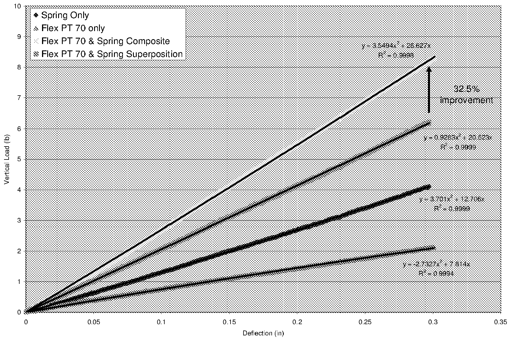
Claims (15)
- A composite material comprising a plurality of springs embedded within a polymer wherein each spring is interwoven with at least one other spring.
- The composite material of claim 1 wherein the springs are entirely polymer-coated.
- The composite material of claim 1 or 2 wherein each spring comprises a coil.
- The composite material of at least one of the previous claims wherein each spring is preferably laterally tensioned with an adjacent spring such that an inner part of each spring or an inner part of each spring coil engages an inner part of an adjacent spring or an inner part of an adjacent spring coil.
- The composite material of at least one of the previous claims wherein each spring is preferably laterally tensioned with an adjacent spring such that an outer part of each spring or an outer part of each spring coil engages an inner part of an adjacent spring or an inner part of an adjacent spring coil.
- The composite material of at least one of the previous claims wherein each spring is preferably laterally compressed with an adjacent spring such that an inner part of each spring or an inner part of each spring coil engages an inner part of an adjacent spring or an inner part of an adjacent spring coil.
- The composite material of at least one of the previous claims wherein each spring is preferably laterally compressed with an adjacent spring such that an outer part of each spring or an outer part of each spring coil engages an inner part of an adjacent spring or an inner part of an adjacent spring coil.
- The composite material of at least one of the previous claims wherein the springs are elliptical.
- The composite material of at least one of the previous claims wherein the springs are constructed of a material from the following group: metal, plastic, polyurethane, rubber, and carbon.
- The composite material of at least one of the previous claims wherein the springs are constructed of preferably normal tensile steel and have a spring outside diameter in a range of from 7 to 11 mm, alternatively 8 to 10 mm such as 8.9 mm, have a wire diameter in a range of from 1 mm to 1.8 mm wire, alternatively 1.2 to 1.6 mm such as 1.4 mm, and/or a pitch in a range of from 5 mm to 10 mm, alternatively 6 mm to 8 mm such as 7.1 mm.
- The composite material of at least one of the previous claims wherein a bending stiffness of the composite material is larger than a bending stiffness of the springs and a bending stiffness of the polymer measured separately prior to forming the composite material.
- The composite material of at least one of the previous claims wherein the polymer is a castable elastomer.
- A non-pneumatic tire wherein the composite material of one of the previous claims forms a toroidal carcass structure extending about an entire circumference of the tire.
- A tire comprising a tire component, the tire component comprising the composite material of one of the previous claims.
- A method of manufacturing a composite material comprising a plurality of springs embedded within a polymer wherein each spring is interwoven with at least one other spring, the method comprising providing a plurality of springs wherein each spring is interwoven with at least one other spring, and embedding the springs within a polymer.
Applications Claiming Priority (1)
| Application Number | Priority Date | Filing Date | Title |
|---|---|---|---|
| US12/870,898 US9616713B2 (en) | 2010-08-30 | 2010-08-30 | Non-pneumatic tire |
Publications (1)
| Publication Number | Publication Date |
|---|---|
| EP2422967A1 true EP2422967A1 (en) | 2012-02-29 |
Family
ID=44719311
Family Applications (1)
| Application Number | Title | Priority Date | Filing Date |
|---|---|---|---|
| EP11179219A Withdrawn EP2422967A1 (en) | 2010-08-30 | 2011-08-29 | Composite material and tire comprising such a material |
Country Status (6)
| Country | Link |
|---|---|
| US (1) | US9616713B2 (en) |
| EP (1) | EP2422967A1 (en) |
| CN (1) | CN102433010A (en) |
| AR (1) | AR083640A1 (en) |
| BR (1) | BRPI1103957A2 (en) |
| IL (1) | IL214713A0 (en) |
Cited By (1)
| Publication number | Priority date | Publication date | Assignee | Title |
|---|---|---|---|---|
| WO2016160188A1 (en) | 2015-04-02 | 2016-10-06 | Baker Hughes Incorporated | Ultrahigh temperature elastic metal composites |
Families Citing this family (20)
| Publication number | Priority date | Publication date | Assignee | Title |
|---|---|---|---|---|
| US8931531B2 (en) * | 2012-05-18 | 2015-01-13 | The Goodyear Tire & Rubber Company | System for non-pneumatic support of a vehicle |
| EP3007909A4 (en) | 2013-06-15 | 2017-03-01 | Ronald Thompson | Annular ring and non-pneumatic tire |
| CN105579248A (en) | 2013-09-24 | 2016-05-11 | 普利司通美国轮胎运营有限责任公司 | Cap ply reinforcement strip in pneumatic tire |
| WO2015068850A1 (en) * | 2013-11-11 | 2015-05-14 | 住友ゴム工業株式会社 | Device for measuring tread ring rigidity and method for measuring uniformity of tread ring |
| US9321312B2 (en) | 2013-12-24 | 2016-04-26 | Bridgestone Americas, Inc. | Airless tire construction having variable stiffness |
| US10427336B2 (en) | 2014-11-20 | 2019-10-01 | Baker Hughes, A Ge Company, Llc | Periodic structured composite and articles therefrom |
| US10953696B2 (en) | 2015-02-04 | 2021-03-23 | Camso Inc | Non-pneumatic tire and other annular devices |
| US10759092B2 (en) | 2015-11-19 | 2020-09-01 | Baker Hughes, A Ge Company, Llc | Methods of making high temperature elastic composites |
| CA3008846C (en) | 2015-12-16 | 2024-02-20 | Ronald H. Thompson | Track system for traction of a vehicle |
| US10450828B2 (en) | 2016-10-28 | 2019-10-22 | Baker Hughes, A Ge Company, Llc | High temperature high extrusion resistant packer |
| CN108973274B (en) | 2017-06-02 | 2020-07-21 | 普利司通美国轮胎运营有限责任公司 | Adhesive system for producing a composite of rubber and a polar thermoset |
| WO2019050548A1 (en) * | 2017-09-11 | 2019-03-14 | Compagnie Generale Des Etablissements Michelin | Spoke for non-pneumatic tire |
| WO2019050547A1 (en) * | 2017-09-11 | 2019-03-14 | Compagnie Generale Des Etablissements Michelin | Spoke for non-pneumatic tire |
| US20220227174A1 (en) * | 2019-05-29 | 2022-07-21 | Bridgestone Corporation | Tire |
| WO2021079834A1 (en) | 2019-10-21 | 2021-04-29 | 株式会社ブリヂストン | Vehicle wheel |
| EP3871902B1 (en) | 2020-02-28 | 2023-07-19 | The Goodyear Tire & Rubber Company | Non-pneumatic tire |
| WO2023043992A1 (en) * | 2021-09-16 | 2023-03-23 | The SMART Tire Company Inc. | Reinforcement of polymers with shape memory alloy elements |
| US12179525B2 (en) | 2021-09-16 | 2024-12-31 | The Smart Tire Company, Inc. | Tire assembly with circumferential shape memory alloy configuration |
| WO2023147159A1 (en) | 2022-01-31 | 2023-08-03 | The SMART Tire Company Inc. | Spring tire wheel assembly with bump stop |
| US20230271451A1 (en) * | 2022-02-25 | 2023-08-31 | The Goodyear Tire & Rubber Company | System for non-pneumatic support of a vehicle |
Citations (13)
| Publication number | Priority date | Publication date | Assignee | Title |
|---|---|---|---|---|
| DE246231C (en) * | ||||
| FR405392A (en) * | 1909-07-19 | 1909-12-28 | Malby George Crofton Dodwell | Advanced tire for bicycle wheels, automobiles and other vehicles |
| GB191106639A (en) * | 1911-03-16 | 1912-06-17 | Ernest Henry Jones | Improvements relating to the Manufacture of Pneumatic Tyres. |
| GB191213013A (en) * | 1912-06-03 | 1912-09-19 | Augustus Doujon Laurent | Improvements in and relating to Tires. |
| GB191205393A (en) * | 1912-03-04 | 1912-12-12 | Frederick Duffield | Improvement in and relating to Spring Tyres. |
| FR459482A (en) * | 1912-06-28 | 1913-11-06 | Wale S Invulnerable Tyre Syndi | Wheel tire and how it is made |
| US1343172A (en) * | 1918-10-10 | 1920-06-08 | Lawrence D Hughes | Resilient tire |
| US1415281A (en) * | 1913-06-06 | 1922-05-09 | Alfred Eugene Harris | Tire cover and the like |
| FR572480A (en) * | 1922-11-15 | 1924-06-06 | Improvements made to the manufacture of imperforable bandages | |
| US1610238A (en) * | 1924-10-13 | 1926-12-14 | Thomas J Benson | Cushion tire |
| DE860262C (en) * | 1944-02-15 | 1952-12-18 | Continental Gummi Werke Ag | Process for the production of vehicle tires |
| EP0588780A1 (en) * | 1992-09-15 | 1994-03-23 | Semperit Reifen Aktiengesellschaft | Reinforcement |
| EP1759612A1 (en) * | 2005-09-01 | 2007-03-07 | Ace Bed Co., Ltd. | Bed mattress using permeable reinforcing member and foaming material, and method of manufacturing the same |
Family Cites Families (77)
| Publication number | Priority date | Publication date | Assignee | Title |
|---|---|---|---|---|
| US1195148A (en) | 1916-08-15 | Walteb thomas newman | ||
| US762740A (en) * | 1904-03-23 | 1904-06-14 | Thomas Midgley | Pneumatic tire. |
| US976710A (en) | 1908-01-31 | 1910-11-22 | Oscar Treier | Vehicle-wheel. |
| US1013656A (en) | 1910-12-16 | 1912-01-02 | William D Hester | Spring-wheel. |
| US1083798A (en) * | 1911-05-25 | 1914-01-06 | Carter J Butts | Automobile-tire. |
| US1133153A (en) * | 1912-03-15 | 1915-03-23 | Ernest Henry Jones | Casing for pneumatic tires. |
| US1090996A (en) | 1912-10-18 | 1914-03-24 | John W Leonard | Spring-tire for vehicle-wheels. |
| US1113036A (en) * | 1914-02-27 | 1914-10-06 | Hesekiah E Mitchell | Tire. |
| US1227348A (en) * | 1914-03-04 | 1917-05-22 | Alfred Edmund Wale | Tire. |
| GB191419768A (en) | 1914-09-14 | 1915-09-02 | Harold Wade | Improvements in or relating to Elevating Trucks. |
| GB191424251A (en) | 1914-12-18 | 1915-11-04 | George Joseph Murphy | Improvements in Spring Wheels. |
| US1258573A (en) | 1917-04-06 | 1918-03-05 | Samuel Johnstone | Automobile cushion-wheel. |
| US1295266A (en) * | 1918-04-19 | 1919-02-25 | Edwin E Bullard | Resilient tire. |
| US1345827A (en) | 1918-10-17 | 1920-07-06 | David D Bohannon | Resilient wheel |
| US1412982A (en) * | 1919-05-03 | 1922-04-18 | Internat Callophone Corp | Casing for telephone sets |
| US1472913A (en) * | 1921-04-14 | 1923-11-06 | Jones Peter | Pneumatic tire |
| US1391985A (en) * | 1921-05-16 | 1921-09-27 | Gaetano E Siino | Spring-tire |
| US1457538A (en) | 1922-10-28 | 1923-06-05 | Mark Louis | Spring wheel |
| US1471580A (en) * | 1923-05-11 | 1923-10-23 | Joseph S Walton | Tire |
| US1561759A (en) * | 1923-10-22 | 1925-11-17 | William O Wetmore | Vehicle tire |
| GB261226A (en) | 1926-02-11 | 1926-11-18 | Frank Richard Rand | A wheel for vehicles for absorbing shock and vibration from roads and railroads |
| US1687206A (en) * | 1927-09-17 | 1928-10-09 | Hatvani Gabriel | Spring tire |
| US1874396A (en) | 1930-03-07 | 1932-08-30 | Harry L Kaufhold | Resilient wheel |
| US2059764A (en) * | 1933-11-03 | 1936-11-03 | Zerillo Frank | Pneumatic tire |
| US3449199A (en) * | 1964-02-13 | 1969-06-10 | George N J Mead | Helical reinforced materials and method of making same |
| US3568748A (en) | 1969-02-17 | 1971-03-09 | Nasa | Resilient wheel |
| US3982576A (en) | 1974-08-09 | 1976-09-28 | Vector Wheel Corporation | Tire structure and method |
| US4071279A (en) * | 1975-04-21 | 1978-01-31 | The Goodyear Tire & Rubber Company | Solid polyurethane tire and wheel assembly |
| FR2472482B1 (en) | 1979-07-25 | 1985-11-08 | Feron De Longcamp Le | NEW DEFORMABLE WHEEL, IN PARTICULAR FOR USE AS A VEHICLE WHEEL OR IN A GEAR |
| GB2059887A (en) | 1979-09-25 | 1981-04-29 | Jones S | Wheels for vehicles |
| GB2109752B (en) | 1981-11-10 | 1985-12-04 | Sydney Jones | Wheel assemblies for vehicles |
| GB8400791D0 (en) * | 1984-01-12 | 1984-02-15 | British Telecomm | Digital filter |
| US4832098A (en) | 1984-04-16 | 1989-05-23 | The Uniroyal Goodrich Tire Company | Non-pneumatic tire with supporting and cushioning members |
| GB8608270D0 (en) | 1986-04-04 | 1986-05-08 | Jones S | Ground-engaging wheels for vehicles |
| US4945962A (en) | 1989-06-09 | 1990-08-07 | The Uniroyal Goodrich Tire Company | Honeycomb non-pneumatic tire with a single web on one side |
| FR2652310A1 (en) | 1989-09-28 | 1991-03-29 | Michelin & Cie | NON-PNEUMATIC DEFORMABLE BANDAGE. |
| CA2043082A1 (en) | 1991-02-27 | 1992-08-28 | James Edward Duddey | Non-pneumatic spare tire |
| US5125443A (en) | 1991-04-16 | 1992-06-30 | Gil Schwartzman | Spring mounted wheel assembly |
| FR2687954A1 (en) | 1992-02-28 | 1993-09-03 | Michelin & Cie | TIRE WITH SEVERAL INDEPENDENT REMOVABLE AND REINFORCED SECTORS. |
| US5265659A (en) | 1992-03-18 | 1993-11-30 | Uniroyal Goodrich Licensing Services, Inc. | Non-pneumatic tire with ride-enhancing insert |
| US5460213A (en) | 1992-03-18 | 1995-10-24 | Uniroyal Goodrich Licensing Services, Inc. | Multiple non-pneumatic tire and process for making it |
| US5386860A (en) | 1992-10-21 | 1995-02-07 | The Goodyear Tire & Rubber Company | Cut resistant tire |
| WO1998043833A1 (en) | 1997-03-27 | 1998-10-08 | Compagnie Generale Des Etablissements Michelin - Michelin & Cie | Non-pneumatic ductile tyre |
| WO1999064256A1 (en) | 1998-06-08 | 1999-12-16 | Paciello Fredy P | Polyform wheel |
| US6209602B1 (en) | 1999-02-03 | 2001-04-03 | The Goodyear Tire & Rubber Company | Industrial service agricultural tire |
| US20050269005A1 (en) | 2000-09-20 | 2005-12-08 | Steinke Richard A | Air no air elastomeric tire |
| US6679306B2 (en) | 2001-12-10 | 2004-01-20 | Amerityre | Run flat tire with an elastomeric inner support |
| JP2003312204A (en) | 2002-04-18 | 2003-11-06 | Topy Ind Ltd | Elastic wheel |
| US6681822B2 (en) | 2002-04-26 | 2004-01-27 | The Goodyear Tire & Rubber Company | Non-pneumatic spare tire |
| US6974519B2 (en) | 2002-05-13 | 2005-12-13 | Amerityre | Tire core package for use in manufacturing a tire with belts, plies and beads and process of tire manufacture |
| JP3890050B2 (en) | 2003-12-22 | 2007-03-07 | 住友ゴム工業株式会社 | Heavy duty tire |
| US6971426B1 (en) | 2004-05-28 | 2005-12-06 | Amerityre | Elastomeric tire with arch shaped shoulders |
| US7094303B2 (en) | 2004-08-02 | 2006-08-22 | Amerityre | Method and apparatus for forming a core of plies, belts and beads and for positioning the core in a mold for forming an elastomeric tire |
| US7399172B2 (en) | 2004-09-04 | 2008-07-15 | Amerityre | Apparatus for vacuum forming an elastomeric tire |
| US7143797B2 (en) | 2005-01-04 | 2006-12-05 | Frederick F. Vannan | Airless tire |
| US7377596B2 (en) | 2005-04-29 | 2008-05-27 | Amerityre | Urethane wheel having a metal core |
| US20060289099A1 (en) | 2005-06-27 | 2006-12-28 | Steinke Richard A | Run flat tire insert system |
| KR100743885B1 (en) * | 2005-09-01 | 2007-07-30 | 주식회사 에이스침대 | Fixing device and fixing method of spring structure and cushion material for mattress |
| FR2893274B1 (en) | 2005-11-15 | 2009-07-17 | Conception & Dev Michelin Sa | NON-PNEUMATIC FLEXIBLE BANDAGE |
| US7438961B2 (en) | 2006-01-10 | 2008-10-21 | Amerityre | Plies sleeve for use in forming an elastomeric tire |
| US7527489B2 (en) | 2006-05-22 | 2009-05-05 | Amerityre | Apparatus for vacuum forming a tire, wheel or other item from an elastomeric material |
| JP5087252B2 (en) | 2006-09-25 | 2012-12-05 | 株式会社ブリヂストン | Non pneumatic tire |
| FR2909035B1 (en) | 2006-11-24 | 2009-10-23 | Delsey Sa | RADIAL DAMPING WHEEL |
| WO2008065407A1 (en) | 2006-11-29 | 2008-06-05 | Royal College Of Art | Vehicle wheel |
| EP1958793A1 (en) | 2006-12-01 | 2008-08-20 | The Royal College of Art | Vehicle wheel |
| US8104524B2 (en) | 2007-03-27 | 2012-01-31 | Resilient Technologies Llc | Tension-based non-pneumatic tire |
| US20080245482A1 (en) | 2007-04-03 | 2008-10-09 | Steinke Richard A | Belt for use in forming a core of plies, beads and belts of a urethane tire |
| US8061398B2 (en) * | 2008-02-25 | 2011-11-22 | Chemtura Corporation | Non-pneumatic tire having angled tread groove wall |
| US8151840B2 (en) | 2008-01-23 | 2012-04-10 | Frederick Forbes Vannan | Method of manufacturing a new airless or pneumatic tire having a reinforced rubber structure and a polyurethane tread |
| US20090183810A1 (en) | 2008-01-23 | 2009-07-23 | Frederick Forbes Vannan | Newly manufactured airless or pneumatic tire having a reinforced rubber structure and a polyurethane tread |
| US20090211677A1 (en) | 2008-02-25 | 2009-08-27 | Palinkas Richard L | Modular tire assembly |
| JP4506853B2 (en) | 2008-02-25 | 2010-07-21 | 横浜ゴム株式会社 | Non-pneumatic tire |
| US20090211681A1 (en) | 2008-02-25 | 2009-08-27 | Palinkas Richard L | Tire and tire rim assembly |
| US7614865B1 (en) | 2008-10-31 | 2009-11-10 | Amerityre Corporation | Method and apparatus for filling a tire and wheel assembly with a closed cell polyurethane foam |
| US8141606B2 (en) * | 2009-05-29 | 2012-03-27 | The Goodyear Tire & Rubber Company | Tire |
| US8662122B2 (en) * | 2010-05-14 | 2014-03-04 | The Goodyear Tire & Rubber Company | System for non-pneumatic support of a vehicle |
| US8720504B2 (en) * | 2011-06-17 | 2014-05-13 | The Goodyear Tire & Rubber Company | System for non-pneumatic support of a vehicle |
-
2010
- 2010-08-30 US US12/870,898 patent/US9616713B2/en active Active
-
2011
- 2011-08-18 IL IL214713A patent/IL214713A0/en unknown
- 2011-08-23 AR ARP110103052A patent/AR083640A1/en unknown
- 2011-08-25 BR BRPI1103957-4A patent/BRPI1103957A2/en not_active IP Right Cessation
- 2011-08-29 EP EP11179219A patent/EP2422967A1/en not_active Withdrawn
- 2011-08-30 CN CN2011102524385A patent/CN102433010A/en active Pending
Patent Citations (13)
| Publication number | Priority date | Publication date | Assignee | Title |
|---|---|---|---|---|
| DE246231C (en) * | ||||
| FR405392A (en) * | 1909-07-19 | 1909-12-28 | Malby George Crofton Dodwell | Advanced tire for bicycle wheels, automobiles and other vehicles |
| GB191106639A (en) * | 1911-03-16 | 1912-06-17 | Ernest Henry Jones | Improvements relating to the Manufacture of Pneumatic Tyres. |
| GB191205393A (en) * | 1912-03-04 | 1912-12-12 | Frederick Duffield | Improvement in and relating to Spring Tyres. |
| GB191213013A (en) * | 1912-06-03 | 1912-09-19 | Augustus Doujon Laurent | Improvements in and relating to Tires. |
| FR459482A (en) * | 1912-06-28 | 1913-11-06 | Wale S Invulnerable Tyre Syndi | Wheel tire and how it is made |
| US1415281A (en) * | 1913-06-06 | 1922-05-09 | Alfred Eugene Harris | Tire cover and the like |
| US1343172A (en) * | 1918-10-10 | 1920-06-08 | Lawrence D Hughes | Resilient tire |
| FR572480A (en) * | 1922-11-15 | 1924-06-06 | Improvements made to the manufacture of imperforable bandages | |
| US1610238A (en) * | 1924-10-13 | 1926-12-14 | Thomas J Benson | Cushion tire |
| DE860262C (en) * | 1944-02-15 | 1952-12-18 | Continental Gummi Werke Ag | Process for the production of vehicle tires |
| EP0588780A1 (en) * | 1992-09-15 | 1994-03-23 | Semperit Reifen Aktiengesellschaft | Reinforcement |
| EP1759612A1 (en) * | 2005-09-01 | 2007-03-07 | Ace Bed Co., Ltd. | Bed mattress using permeable reinforcing member and foaming material, and method of manufacturing the same |
Cited By (2)
| Publication number | Priority date | Publication date | Assignee | Title |
|---|---|---|---|---|
| WO2016160188A1 (en) | 2015-04-02 | 2016-10-06 | Baker Hughes Incorporated | Ultrahigh temperature elastic metal composites |
| EP3277856A4 (en) * | 2015-04-02 | 2018-12-12 | Baker Hughes, A Ge Company, Llc | Ultrahigh temperature elastic metal composites |
Also Published As
| Publication number | Publication date |
|---|---|
| BRPI1103957A2 (en) | 2015-08-25 |
| CN102433010A (en) | 2012-05-02 |
| US20120048440A1 (en) | 2012-03-01 |
| AR083640A1 (en) | 2013-03-13 |
| IL214713A0 (en) | 2012-02-29 |
| US9616713B2 (en) | 2017-04-11 |
Similar Documents
| Publication | Publication Date | Title |
|---|---|---|
| EP2664463B1 (en) | System for non-pneumatic support of a vehicle | |
| EP2386430B1 (en) | Tire comprising springs and method of manufacturing a tire | |
| US9616713B2 (en) | Non-pneumatic tire | |
| US9016336B2 (en) | System for non-pneumatic support of a vehicle | |
| EP2435256B1 (en) | Airless tire comprising helical springs | |
| CN111511580B (en) | Reinforced resilient support for non-pneumatic tires | |
| CN111867853B (en) | Non-pneumatic tire | |
| US11577548B2 (en) | Reinforced resilient support for a non-pneumatic tire | |
| CN111511581B (en) | Reinforced annular support for tires | |
| US11794513B2 (en) | Wheel for a support structure |
Legal Events
| Date | Code | Title | Description |
|---|---|---|---|
| AK | Designated contracting states |
Kind code of ref document: A1 Designated state(s): AL AT BE BG CH CY CZ DE DK EE ES FI FR GB GR HR HU IE IS IT LI LT LU LV MC MK MT NL NO PL PT RO RS SE SI SK SM TR |
|
| AX | Request for extension of the european patent |
Extension state: BA ME |
|
| PUAI | Public reference made under article 153(3) epc to a published international application that has entered the european phase |
Free format text: ORIGINAL CODE: 0009012 |
|
| 17P | Request for examination filed |
Effective date: 20120829 |
|
| 17Q | First examination report despatched |
Effective date: 20130410 |
|
| GRAP | Despatch of communication of intention to grant a patent |
Free format text: ORIGINAL CODE: EPIDOSNIGR1 |
|
| INTG | Intention to grant announced |
Effective date: 20160422 |
|
| GRAS | Grant fee paid |
Free format text: ORIGINAL CODE: EPIDOSNIGR3 |
|
| STAA | Information on the status of an ep patent application or granted ep patent |
Free format text: STATUS: THE APPLICATION IS DEEMED TO BE WITHDRAWN |
|
| 18D | Application deemed to be withdrawn |
Effective date: 20160903 |