FR2687954A1 - TIRE WITH SEVERAL INDEPENDENT REMOVABLE AND REINFORCED SECTORS. - Google Patents
TIRE WITH SEVERAL INDEPENDENT REMOVABLE AND REINFORCED SECTORS. Download PDFInfo
- Publication number
- FR2687954A1 FR2687954A1 FR9202483A FR9202483A FR2687954A1 FR 2687954 A1 FR2687954 A1 FR 2687954A1 FR 9202483 A FR9202483 A FR 9202483A FR 9202483 A FR9202483 A FR 9202483A FR 2687954 A1 FR2687954 A1 FR 2687954A1
- Authority
- FR
- France
- Prior art keywords
- reinforcement
- rim
- tire
- meridian
- rods
- Prior art date
- Legal status (The legal status is an assumption and is not a legal conclusion. Google has not performed a legal analysis and makes no representation as to the accuracy of the status listed.)
- Withdrawn
Links
Classifications
-
- B—PERFORMING OPERATIONS; TRANSPORTING
- B60—VEHICLES IN GENERAL
- B60C—VEHICLE TYRES; TYRE INFLATION; TYRE CHANGING; CONNECTING VALVES TO INFLATABLE ELASTIC BODIES IN GENERAL; DEVICES OR ARRANGEMENTS RELATED TO TYRES
- B60C5/00—Inflatable pneumatic tyres or inner tubes
- B60C5/18—Sectional casings, e.g. comprising replaceable arcuate parts
-
- B—PERFORMING OPERATIONS; TRANSPORTING
- B60—VEHICLES IN GENERAL
- B60C—VEHICLE TYRES; TYRE INFLATION; TYRE CHANGING; CONNECTING VALVES TO INFLATABLE ELASTIC BODIES IN GENERAL; DEVICES OR ARRANGEMENTS RELATED TO TYRES
- B60C5/00—Inflatable pneumatic tyres or inner tubes
-
- Y—GENERAL TAGGING OF NEW TECHNOLOGICAL DEVELOPMENTS; GENERAL TAGGING OF CROSS-SECTIONAL TECHNOLOGIES SPANNING OVER SEVERAL SECTIONS OF THE IPC; TECHNICAL SUBJECTS COVERED BY FORMER USPC CROSS-REFERENCE ART COLLECTIONS [XRACs] AND DIGESTS
- Y10—TECHNICAL SUBJECTS COVERED BY FORMER USPC
- Y10T—TECHNICAL SUBJECTS COVERED BY FORMER US CLASSIFICATION
- Y10T152/00—Resilient tires and wheels
- Y10T152/10—Tires, resilient
- Y10T152/10135—Armored
- Y10T152/10171—Casing construction
- Y10T152/1018—Embedded
- Y10T152/10189—Metal
-
- Y—GENERAL TAGGING OF NEW TECHNOLOGICAL DEVELOPMENTS; GENERAL TAGGING OF CROSS-SECTIONAL TECHNOLOGIES SPANNING OVER SEVERAL SECTIONS OF THE IPC; TECHNICAL SUBJECTS COVERED BY FORMER USPC CROSS-REFERENCE ART COLLECTIONS [XRACs] AND DIGESTS
- Y10—TECHNICAL SUBJECTS COVERED BY FORMER USPC
- Y10T—TECHNICAL SUBJECTS COVERED BY FORMER US CLASSIFICATION
- Y10T152/00—Resilient tires and wheels
- Y10T152/10—Tires, resilient
- Y10T152/10495—Pneumatic tire or inner tube
- Y10T152/10522—Multiple chamber
- Y10T152/10531—Cylinder and piston
- Y10T152/1054—Mutually free walls
- Y10T152/10549—Interfitting
-
- Y—GENERAL TAGGING OF NEW TECHNOLOGICAL DEVELOPMENTS; GENERAL TAGGING OF CROSS-SECTIONAL TECHNOLOGIES SPANNING OVER SEVERAL SECTIONS OF THE IPC; TECHNICAL SUBJECTS COVERED BY FORMER USPC CROSS-REFERENCE ART COLLECTIONS [XRACs] AND DIGESTS
- Y10—TECHNICAL SUBJECTS COVERED BY FORMER USPC
- Y10T—TECHNICAL SUBJECTS COVERED BY FORMER US CLASSIFICATION
- Y10T152/00—Resilient tires and wheels
- Y10T152/10—Tires, resilient
- Y10T152/10495—Pneumatic tire or inner tube
- Y10T152/10522—Multiple chamber
- Y10T152/10531—Cylinder and piston
- Y10T152/1054—Mutually free walls
- Y10T152/10558—Balls
-
- Y—GENERAL TAGGING OF NEW TECHNOLOGICAL DEVELOPMENTS; GENERAL TAGGING OF CROSS-SECTIONAL TECHNOLOGIES SPANNING OVER SEVERAL SECTIONS OF THE IPC; TECHNICAL SUBJECTS COVERED BY FORMER USPC CROSS-REFERENCE ART COLLECTIONS [XRACs] AND DIGESTS
- Y10—TECHNICAL SUBJECTS COVERED BY FORMER USPC
- Y10T—TECHNICAL SUBJECTS COVERED BY FORMER US CLASSIFICATION
- Y10T152/00—Resilient tires and wheels
- Y10T152/10—Tires, resilient
- Y10T152/10495—Pneumatic tire or inner tube
- Y10T152/10522—Multiple chamber
- Y10T152/10576—Annular chambers
- Y10T152/10585—Annular chambers with simultaneous inflating means
Landscapes
- Engineering & Computer Science (AREA)
- Mechanical Engineering (AREA)
- Tires In General (AREA)
Abstract
Description
L'invention concerne un pneumatique formé de plusieurs secteurs pneumatiques montés sur une même jante et circonférentiellement adjacents, chaque secteur étant gonflé, et amovible de manière à pouvoir être remplacé aisément dans le cas où il aurait été endommagé. L'invention concerne également l'ensemble du pneumatique avec une jante de montage adaptée aux secteurs dudit pneumatique.The invention relates to a tire formed from several pneumatic sectors mounted on the same rim and circumferentially adjacent, each sector being inflated, and removable so that it can be easily replaced in the event that it has been damaged. The invention also relates to the whole tire with a mounting rim adapted to the sectors of said tire.
Bien que tous les types de pneumatique puissent être concernés, il est connu que ce sont les pneumatiques pour engins de Génie Civil, roulant dans des mines à ciel ouvert ou souterraines, dans les chantiers de toute sorte, qui sont sujets de la part du sol à de nombreuses agressions. Ils nécessitent donc, plus que tout autre pneumatique, des démontages, des réparations, des remontages fréquents, à moins d'être classés déchets et mis au rebut dans de nombreux cas avant qu'ils soient convenablement usés. Les dimensions des pneumatiques concernés étant les plus grandes et en outre s'accroissant régulièrement dans le temps, les problèmes sont aggravés : les démontages, les réparations et les remontages demandent des moyens de plus en plus volumineux et de plus en plus onéreux.Although all types of tire can be affected, it is known that it is the tires for civil engineering vehicles, rolling in surface or underground mines, in construction sites of all kinds, which are subject to the soil numerous assaults. They therefore require, more than any other tire, disassembly, repair, frequent reassembly, unless they are classified as waste and discarded in many cases before they are properly used. The dimensions of the tires concerned being the largest and further increasing regularly over time, the problems are aggravated: disassembly, repair and reassembly require increasingly bulky and increasingly expensive means.
Le principe de fabriquer un pneumatique fait de plusieurs secteurs gonflables, indépendants les uns des autres, démontables individuellement de la jante, est largement connu par l'art antérieur et on peut citer les brevets américains 12 33 853, 1 311 806, 1 322 685 ou 4 153 094.The principle of manufacturing a tire made of several inflatable sectors, independent of each other, individually removable from the rim, is widely known in the prior art and mention may be made of American patents 12 33 853, 1 311 806, 1 322 685 or 4,153,094.
Ces documents, pour la plupart anciens, concernent soit des secteurs pneumatiques fermés, soit des systèmes permettant à ces secteurs d'être étanches. Le brevet US 4 153 094 décrit en particulier un système d'accrochage où une tringle circulaire renforce le bourrelet circulaire d'un secteur pneumatique. Cette tringle étant percée de trous le long de son pourtour, le secteur est alors attaché par vissage à un plateau lui-même fixé à une jante plate.These documents, for the most part old, relate to either closed pneumatic sectors or systems enabling these sectors to be sealed. US patent 4,153,094 describes in particular a fastening system where a circular rod reinforces the circular bead of a pneumatic sector. This rod being pierced with holes along its periphery, the sector is then attached by screwing to a plate itself fixed to a flat rim.
L'invention répond à une double préoccupation. Premièrement, les secteurs amovibles gonflables se doivent d'être résistants aux agressions du sol, que ce soit isolément ou pris dans leur ensemble. En effet, lors du roulage, plusieurs secteurs sont simultanément chargés et en contact avec le sol : une certaine cohésion entre secteurs est nécessaire pour que les efforts soient répartis sur tous les secteurs concernés. En second lieu les secteurs amovibles doivent avoir une structure telle que leurs montage et démontage de la jante soit aisée et rapide.The invention responds to a double concern. First, the removable inflatable sectors must be resistant to attack by the ground, either individually or as a whole. Indeed, during taxiing, several sectors are simultaneously loaded and in contact with the ground: a certain cohesion between sectors is necessary so that the forces are distributed over all the sectors concerned. Secondly, the removable sectors must have a structure such that their mounting and dismounting of the rim is easy and quick.
Ainsi, conformément à l'invention, le pneumatique constitué de plusieurs secteurs pneumatiques identiques, gonflables amovibles et circonférentiellement adjacents lorsqu'ils sont montés sur une jante adaptée à base circulairement continue est caractérisé en ce que chaque-secteur de hauteur sur jante (H), de largeur méridienne (B), de largeur circonférentielle (C), comprend une bande de roulement réunie à quatre flancs, deux de ces flancs étant circonférentiellement adjacents aux flancs des secteurs voisins et les deux autres formant les flancs du pneumatique, ces flancs se terminant respectivement par des bourrelets méridiens non liés à la jante de montage et renforcés par des tringles méridiennes et par des bourrelets circonférentiels assurant le montage des secteurs sur la jante et renforcés par des tringles circonférentielles liées aux tringles méridiennes et auxquelles au moins une armature de renfort de fils ou câbles inextensibles est ancrée, cette armature étant, au sommet du secteur, radialement juxtaposée à au moins une armature de renforcement de la bande de roulement.Thus, in accordance with the invention, the tire made up of several identical pneumatic sectors, removable inflatable and circumferentially adjacent when they are mounted on a rim adapted to a circularly continuous base is characterized in that each height sector on rim (H) , of meridian width (B), of circumferential width (C), comprises a tread joined to four sidewalls, two of these sidewalls being circumferentially adjacent to the sidewalls of the neighboring sectors and the other two forming the sidewalls of the tire, these sidewalls ending respectively with meridian beads not linked to the mounting rim and reinforced by meridian rods and by circumferential beads ensuring the mounting of the sectors on the rim and reinforced by circumferential rods linked to the meridian rods and to which at least one reinforcing reinforcement of inextensible wires or cables is anchored, this arma ture being, at the top of the sector, radially juxtaposed with at least one reinforcement for reinforcing the tread.
L'armature de renfort, peut être formée d'au moins une nappe de fils ou câbles radiaux, c'est-à-dire dans des plans contenant l'axe de rotation du pneumatique. Elle peut aussi être avantageusement formée d'au moins deux nappes de fils ou câbles, parallèles entre eux dans chaque nappe, et croisés d'une nappe à la suivante.The reinforcing reinforcement may be formed of at least one ply of radial wires or cables, that is to say in planes containing the axis of rotation of the tire. It can also advantageously be formed from at least two plies of wires or cables, mutually parallel in each ply, and crossed from one ply to the next.
Par radialement juxtaposée, il faut comprendre que l'armature de renforcement de la bande de roulement peut être disposée soit radialement sur l'armature de renfort soit radialement sous l'armature de renfort.By radially juxtaposed, it should be understood that the reinforcement reinforcement of the tread can be arranged either radially on the reinforcement reinforcement or radially under the reinforcement reinforcement.
L'armature de renfort est ancrée aux tringles circonférentielles dites tringles de montage : par le terme ancrée il faut entendre qu'elle peut être enroulée autour de ces tringles circonférentielles en formant des retournements, comme connu en soit, mais qu'elle peut être aussi reliée à ces tringles circonférentielles par d'autres moyens, et en particulier, de manière avantageuse, par le moyen de nappe(s) de renforcement additionnelle(s) enroulée(s) autour des tringles circonférentielles et entre les bords desquelles viennent s'insérer les bords de la nappe radiale.The reinforcing reinforcement is anchored to the circumferential rods called assembly rods: by the term anchored it should be understood that it can be wrapped around these circumferential rods by forming reversals, as is known per se, but that it can also be connected to these circumferential rods by other means, and in particular, advantageously, by means of additional reinforcement ply (s) wound (s) around the circumferential rods and between the edges of which are inserted the edges of the radial ply.
De manière préférentielle, les nappes de renforcement additionnelles sont formées de fils ou câbles faisant avec la direction circonférentielle du pneumatique un angle faible -compris entre 30 et 600.Preferably, the additional reinforcing plies are formed of wires or cables making a slight angle with the circumferential direction of the tire - between 30 and 600.
Dans le cas d'une armature de renfort dite radiale, elle peut être avantageusement formée d'un unique fil ou câble qu'on a enroulé autour des deux tringles circonférentielles respectivement, ce qui permet avantageusement d'éviter toutes les dégradations dues à des cisaillements internappes, tout en assurant un excellent ancrage.In the case of a so-called radial reinforcement, it can advantageously be formed from a single wire or cable which has been wound around the two circumferential rods respectively, which advantageously makes it possible to avoid all the damage due to shearing internappes, while ensuring excellent anchoring.
Vu dans un plan radial, le profil méridien de l'armature de renfort présente avec le profil méridien de l'armature de renforcement de la bande de roulement deux points d'intersection situés symétriquement de part et d'autre du plan équatorial. Il est avantageux que ces points d'intersection correspondent aux extrémités axiales de l'armature de renforcement, et que le profil méridien de l'armature de renfort ait en ces points des tangentes faisant avec l'axe de rotation de l'ensemble pneumatique des angles (A) tel que RA - RE tg A =
2RA lorsque le secteur est monté sur jante et gonflé à sa pression de service, RÂ étant le rayon des points (A) d'intersection entre le profil méridien de l'armature de renfort et le profil méridien de l'armature de renforcement de la bande de roulement,
RE étant le rayon du point E du profil méridien de l'armature de renfort le plus éloigné axialement du plan équatorial de l'ensemble pneumatique, et A étant la largeur, mesurée axialement, de l'armature de renforcement de la bande de roulement. I1 est alors particulièrement avantageux, afin que ce profil méridien soit le plus stable possible, que l'armature de renfort soit, dans la région du sommet du secteur, disposée radialement au dessus de l'armature de renforcement de la bande de roulement, armature de renforcement qui aura une rigidité méridienne de flexion élevée. I1 faut entendre par rigidité méridienne de flexion, si F est la force nécessaire pour obtenir la flèche (e) d'une armature de renforcement encastrée de longueur circonférentielle unité et de largeur axiale L, le rapport e . Cette rigidité de flexion méridienne sera dite élevée si elle est au moins égale à 350 daN par mm de longueur circonférentielle.Seen in a radial plane, the meridian profile of the reinforcing reinforcement presents with the meridian profile of the reinforcing reinforcement of the tread two intersection points located symmetrically on either side of the equatorial plane. It is advantageous that these points of intersection correspond to the axial ends of the reinforcement, and that the meridian profile of the reinforcement has tangents at these points forming with the axis of rotation of the pneumatic assembly angles (A) such that RA - RE tg A =
2RA when the sector is mounted on a rim and inflated to its operating pressure, RÂ being the radius of the points (A) of intersection between the meridian profile of the reinforcement reinforcement and the meridian profile of the reinforcement reinforcement of the tread,
RE being the radius of point E of the meridian profile of the reinforcement armature most axially distant from the equatorial plane of the pneumatic assembly, and A being the width, measured axially, of the reinforcement armature of the tread. It is then particularly advantageous, so that this meridian profile is as stable as possible, that the reinforcing reinforcement is, in the region at the top of the sector, disposed radially above the reinforcement reinforcement of the tread, reinforcement reinforcement which will have a high bending meridian stiffness. It should be understood by meridian bending stiffness, if F is the force necessary to obtain the deflection (e) of an embedded reinforcing reinforcement of circumferential length unit and axial width L, the ratio e. This meridian flexural rigidity will be said to be high if it is at least equal to 350 daN per mm of circumferential length.
L'armature de renforcement de la bande de roulement peut être formée d'une ou plusieurs couches de renforcement, formées de nappes de fils ou câbles ou lames, textiles, plastiques ou métalliques, orientés par rapport à la direction circonférentielle de l'ensemble des secteurs selon des angles nuls, droits, aigus, égaux ou différents, le nombre de ces nappes caoutchoutées étant fonction de la résistance de l'armature ainsi formée. I1 peut aussi s'agir de plaques de matériau composite plastique, c'est-à-dire de couche de matière plastique dans laquelle sont incluses des fibres courtes ou longues. Les plaques peuvent aussi être constituées de matière plastique seule, non armée, ou en métal, et peuvent être utilisées seules ou en complément de nappes usuelles de fils ou câbles.The reinforcing reinforcement of the tread may be formed of one or more reinforcing layers, formed of plies of wires or cables or blades, textiles, plastics or metals, oriented with respect to the circumferential direction of all of the sectors at zero, straight, acute, equal or different angles, the number of these rubberized plies being a function of the resistance of the frame thus formed. It can also be sheets of plastic composite material, that is to say a layer of plastic material in which short or long fibers are included. The plates can also be made of a single, unreinforced plastic material or of metal, and can be used alone or in addition to the usual plies of wires or cables.
Les deux tringles méridiennes qui renforcent les bourrelets méridiens sont des tringles se trouvant dans des plans méridiens ou radiaux du pneumatique formé par les secteurs adjacents, lesdits plans méridiens ou radiaux étant des plans contenant l'axe de rotation du pneumatique, les deux tringles circonférentielles étant dans des plans parallèles au plan équatorial et perpendiculaires à l'axe de rotation du pneumatique formé par les secteurs. Les tringles méridiennes et les tringles circonférentielles ne sont pas indépendantes les unes des autres mais sont liées entre elles.The two meridian rods which reinforce the meridian beads are rods located in meridian or radial planes of the tire formed by the adjacent sectors, said meridian or radial planes being planes containing the axis of rotation of the tire, the two circumferential rods being in planes parallel to the equatorial plane and perpendicular to the axis of rotation of the tire formed by the sectors. The meridian rods and the circumferential rods are not independent of each other but are linked together.
Les flancs de secteurs circonférentiellement adjacents les uns aux autres, ou flancs intersecteurs peuvent être constitués d'un simple vulcanisat. De manière préférentielle, ils seront renforcés par une armature de carcasse d'au moins une nappe de fils ou câbles inextensibles, nappe dont les bords seront ancrés aux tringles méridiennes.The sides of sectors circumferentially adjacent to each other, or intersector sides can be made of a simple vulcanizate. Preferably, they will be reinforced by a carcass reinforcement of at least one ply of inextensible wires or cables, a ply whose edges will be anchored to the meridian rods.
Cette armature de carcasse est une armature dont les fils ou câbles inextensibles suivent un tracé selon un profil déterminé allant d'une tringle méridienne à la tringle méridienne circonférentiellement opposée. L'ensemble des fils ou câbles peut couvrir entièrement la surface, qui n'est pas de révolution, comprise entre les tringles méridiennes et les tringles circonférentielles. Mais l'armature de carcasse peut être aussi partielle, les fils ou câbles couvrant seulement une surface comprise entre les tringles méridiennes et deux plans parallèles au plan équatorial du pneumatique, à égale distance dudit plan équatorial et plus proches dudit plan que les plans contenant les tringles circonférentielles. Les deux plans cités ci-dessus seront avantageusement les deux plans définissant la largeur axiale de la ou des couches de renforcement de la bande de roulement.This carcass reinforcement is a reinforcement whose inextensible wires or cables follow a path according to a determined profile going from a meridian rod to the circumferentially opposite meridian rod. The set of wires or cables can entirely cover the surface, which is not of revolution, comprised between the meridian rods and the circumferential rods. However, the carcass reinforcement may also be partial, the wires or cables covering only an area between the meridian rods and two planes parallel to the equatorial plane of the tire, equidistant from said equatorial plane and closer to said plane than the planes containing the circumferential rods. The two planes mentioned above will advantageously be the two planes defining the axial width of the reinforcing layer or layers of the tread.
L'armature de carcasse peut être formée de deux nappes dont les fils ou câbles sont croisés d'une nappe à la suivante, en formant un angle au plus égal à 45O par rapport au plan équatorial du pneumatique, et dans le plan méridien séparant circonférentiellement un secteur en deux parties identiques.The carcass reinforcement may be formed of two plies, the wires or cables of which are crossed from one ply to the next, at an angle at most equal to 45 ° with respect to the equatorial plane of the tire, and in the meridian plane separating circumferentially a sector in two identical parts.
Elle est avantageusement formée d'une nappe unique dont les fils ou câbles sont alors contenus dans des plans perpendiculaires aux deux tringles méridiennes du secteur.It is advantageously formed of a single sheet of which the wires or cables are then contained in planes perpendicular to the two meridian rods of the sector.
Les fils ou câbles constituant cette armature sont retournés autour des tringles meridiennes de manière à former préférentiellement un retournement à hauteur constante.The wires or cables constituting this frame are turned around the meridian rods so as to preferably form a turn at constant height.
Les secteurs de pneumatique ainsi renforcés, peuvent être gonflables individuellement à l'aide de chambres à air individuelles et appropriées, en nombre égal à celui des secteurs, ou alors gonflables dans leur ensemble, avec ou sans chambre à air ; dans ce dernier cas nous sommes en présence d'un ensemble de secteurs dit "sans chambre", chaque secteur étant alors recouvert intérieurement d'une couche de vulcanisat présentant la propriété d'être imperméable au gaz de gonflage du pneumatique.The tire sectors thus reinforced, can be inflatable individually using individual and appropriate air chambers, in a number equal to that of the sectors, or else inflatable as a whole, with or without an air chamber; in the latter case, we are in the presence of a set of so-called "chamberless" sectors, each sector then being internally covered with a layer of vulcanizate having the property of being impermeable to the inflation gas of the tire.
Dans le cas de l'ensemble des secteurs gonflé à la pression de service au moyen d'une chambre à air unique, cette dernière peut être, de manière simple, torique, ou alors une chambre bridée méridiennement par un renfort, sous forme de fil, câble, tringle ou nappe étroite à plusieurs endroits équidistants circonférentiellement. Une telle chambre à air unique peut être continue circonférentiellement, mais elle peut être aussi discontinue, c'est-à-dire comportant deux extrémités fermées.In the case of all the sectors inflated to operating pressure by means of a single air chamber, the latter may be, in a simple manner, toric, or else a chamber flanged meridiously by a reinforcement, in the form of wire , cable, rod or narrow sheet in several places equidistant circumferentially. Such a single air chamber can be circumferentially continuous, but it can also be discontinuous, that is to say having two closed ends.
Si l'on appelle (fig 2a) Rs la distance séparant l'axe de rotation du pneumatique formé par les secteurs du point de l'armature de renfort d'un secteur le plus éloigné dudit axe, et Rm la distance séparant le même axe de rotation du point d'une tringle méridienne le plus éloigné dudit axe, la différence Rs - Rm sera préférentiellement comprise entre 0,1 (Rs - Rc) et 0,5 (Rs - Rc), dans le cas de l'utilisation pour le gonflage à la pression de service d'une chambre à air, et au moins égale à 0,2 (Rs - Rc) dans le cas où l'ensemble des secteurs est gonflé sans chambre à air, Rc étant le rayon des tringles circonférentielles du secteur. Ces variantes permettent avantageusement une bonne continuité de roulement des secteurs en évitant toute dégradation des chambres à air individuelles dans lue'premier cas, en permettant l'étanchéité des secteurs dans le deuxième cas, les tringles méridiennes en regard de deux secteurs adjacents étant jointives aux épaisseurs de gomme près. Dans le cas de l'ensemble gonflable sans chambre à air, les flancs méridiens, respectivement des deux secteurs adjacents sont en contact, à la jonction des deux secteurs, sur une hauteur (h), importante, égale à au moins 0,3 (Rs - Rc), cette hauteur (h), mesurée perpendiculairement à la portion méridienne de tringle, étant sensiblement constante sur les flancs méridiens des secteurs.If we call (fig 2a) Rs the distance separating the axis of rotation of the tire formed by the sectors of the point of the reinforcing reinforcement from a sector furthest from said axis, and Rm the distance separating the same axis of rotation of the point of a meridian rod furthest from said axis, the difference Rs - Rm will preferably be between 0.1 (Rs - Rc) and 0.5 (Rs - Rc), in the case of use for inflation at the operating pressure of an inner tube, and at least equal to 0.2 (Rs - Rc) in the case where all the sectors are inflated without an inner tube, Rc being the radius of the circumferential rods of the sector. These variants advantageously allow good rolling continuity of the sectors by avoiding any deterioration of the individual air chambers in the first case, by allowing the sectors to be sealed in the second case, the meridian rods facing two adjacent sectors being joined to the gum thicknesses close. In the case of the inflatable assembly without an inner tube, the meridian sides, respectively of the two adjacent sectors are in contact, at the junction of the two sectors, over a significant height (h), equal to at least 0.3 ( Rs - Rc), this height (h), measured perpendicular to the meridian portion of the rod, being substantially constant on the meridian flanks of the sectors.
Les tringles méridiennes sont avantageusement inextensibles sous effort de tension, et présentent une faible rigidité de flexion dans leurs plans, c'est-à-dire en présence d'un moment de flexion exercé dans leurs plans. The meridian rods are advantageously inextensible under tension force, and have a low bending stiffness in their planes, that is to say in the presence of a bending moment exerted in their planes.
Cette faible rigidité permet des changements de courbure des tringles méridiennes de tringles sans générer des contraintes internes d'extension et de compression néfastes pour lesdites tringles, qui seront avantageusement formées d'un assemblage de fils ou câbles tressés entre eux ou obtenu par enroulement d'un fil ou câble pour former plusieurs spires. Quant aux tringles circonférentielles elles sont de préférence inextensibles et présentent une grande rigidité à la flexion.This low rigidity allows changes in the curvature of the rods meridian rods without generating internal stresses of extension and compression harmful to said rods, which will advantageously be formed from an assembly of wires or cables braided together or obtained by winding a wire or cable to form several turns. As for the circumferential rods, they are preferably inextensible and have a high rigidity in bending.
Ces tringles circonférentielles peuvent être formées de tiges, de tubes ou de rubans d'acier, avec des extrémités circonférentielles courbes ou retournées sur elles-mêmes.These circumferential rods can be formed of rods, tubes or steel bands, with circumferential ends curved or turned over on themselves.
Deux tringles méridiennes et deux tringles circonférentielles peuvent former une seule tringle unique. Une telle tringle est alors obtenue, par exemple, par le tressage de fils ou câbles sur les portions de tubes, tiges ou rubans pour former les parties circonférentielles et le tressage seul pour former les parties méridiennes. Elle peut aussi être obtenue par l'assemblage de plusieurs spires de fils ou câbles et le passage à l'intérieur des portions de tube, ou l'assemblage avec les tiges ou rubans circonférentiels et serrage par colliers.Two meridian rods and two circumferential rods can form a single single rod. Such a rod is then obtained, for example, by braiding wires or cables on the portions of tubes, rods or ribbons to form the circumferential parts and the braiding alone to form the meridian parts. It can also be obtained by assembling several turns of wires or cables and passing them inside the tube portions, or assembling them with circumferential rods or ribbons and tightening by collars.
De manière préférentielle les tringles circonférentielles seront liées à la jante de montage de façon solide par des moyens appropriés, autres que la jante et les bourrelets.Preferably, the circumferential rods will be securely connected to the mounting rim by suitable means, other than the rim and the beads.
Afin que la jonction entre deux secteurs adjacents offre une bonne résistance à la pénétration de cailloux ou objets divers et aux conséquences de cette pénétration afin de favoriser l'étanchéité de l'ensemble, il est avantageux que les flancs respectivement de deux secteurs adjacents qui se font face soient pourvus, pour lun, d'une rainure présentant sur ledit flanc soit un tracé courbe continu soit préférentiellement un tracé ondulé, et pour l'autre de la saillie correspondante de manière à ce que cette dernière s'emboîte dans la rainure du flanc qui fait face.So that the junction between two adjacent sectors offers good resistance to the penetration of pebbles or various objects and to the consequences of this penetration in order to promote the tightness of the assembly, it is advantageous that the sides respectively of two adjacent sectors which are face are provided, for one, with a groove having on said flank either a continuous curved line or preferably a wavy line, and for the other of the corresponding projection so that the latter fits into the groove of the facing flank.
Les secteurs ainsi réalisés sont montés sur une jante unique monobloc. Afin de faciliter les manipulations des secteurs, et en particulier de faciliter leur montage et démontage, la jante de montage a des rebords de jante s'étendant soit radialement vers l'intérieur en direction de l'axe de rotation, soit radialement vers l'extérieur. Dans le premier cas, les rebords sont rendus discontinus circonférentiellement par la présence d'évidements, ceux-ci permettant la mise en place des bourrelets constitués autour des tringles circonférentielles, tringles se mettant en place axialement à l'intérieur des rebords de jante.The sectors thus produced are mounted on a single monobloc rim. In order to facilitate the handling of the sectors, and in particular to facilitate their assembly and disassembly, the mounting rim has rim flanges extending either radially inwards towards the axis of rotation, or radially towards the outside. In the first case, the flanges are made circumferentially discontinuous by the presence of recesses, these allowing the establishment of the beads formed around the circumferential rods, rods being placed axially inside the rim flanges.
De préférence et de manière connue, les rebords de jante ont des contours extérieurs arrondis de manière à ce que I'armatùre de carcasse et les nappes additionnelles viennent se poser sur les rebords sans création de concentration de contraintes.Preferably and in known manner, the rim flanges have rounded external contours so that the carcass reinforcement and the additional plies come to rest on the flanges without creating a concentration of stresses.
Dans le deuxième cas, c'est-à-dire le cas d'utilisation d'une jante à rebords tournés radialement vers l'extérieur, deux options peuvent se présenter. La première concerne l'utilisation d'une jante répondant aux normes admises avec des rebords, dont les sommets arrondis en général sont axialement à l'extérieur des parois verticales des rebords.In the second case, that is to say the case of using a rim with flanges facing radially outward, two options may arise. The first relates to the use of a rim meeting the accepted standards with flanges, the rounded tops of which are generally axially outside the vertical walls of the flanges.
Le montage des bourrelets circonférentiels d'un secteur se fait alors par fixation solide. La deuxième option concerne l'utilisation d'une jante avec des rebords comportant des sommets dont les extrémités sont tournées axialement vers l'intérieur, ces sommets formant ainsi avec les sièges de jante des rainures d'emboîtage, de montage des bourrelets de forme adaptée de chaque secteur.The circumferential beads of a sector are then assembled by solid fixing. The second option relates to the use of a rim with flanges having vertices whose ends are turned axially inwards, these vertices thus forming with the rim seats grooves for fitting, mounting of the beads of suitable shape. of each sector.
Les caractéristiques, avantages et les modes d'éxécution de la présente invention ressortiront plus clairement de la description donnée ci-après prise en référence au dessin annexé sur lequel - la figure 1 représente l'ensemble roulant formé de secteurs
pneumatiques monté sur jante, - la figure 2a représente, vu en section selon la ligne YY
de la figure 1, un des secteurs formant le pneumatique,
avec des bourrelets armés d'une tringle unique.The characteristics, advantages and modes of execution of the present invention will emerge more clearly from the description given below taken with reference to the appended drawing in which - Figure 1 represents the rolling assembly formed by sectors
tires mounted on rim, - Figure 2a represents, seen in section along line YY
in FIG. 1, one of the sectors forming the tire,
with beads armed with a single rod.
- La figure 2b représente, vu en section selon la ligne XX
de la figure 2a un des secteurs du pneumatique non monté
sur jante.- Figure 2b shows, seen in section along line XX
in FIG. 2a one of the sectors of the tire not mounted
on rim.
- La figure 3a représente, vus en section selon la ligne YY
de la figure 1 des secteurs formant le pneumatique avec
des portions circonférentielles de tringle sous forme de
''cavaliersll, permettant une attache solide à la jante.- Figure 3a represents, seen in section along the line YY
of FIG. 1 of the sectors forming the tire with
circumferential portions of rod in the form of
'' riders, allowing a solid attachment to the rim.
- la figure 3b représente, vu en section selon la ligne XX
de la figure 3a un des secteurs pneumatiques non monté sur
jante.- Figure 3b shows, seen in section along line XX
of FIG. 3a one of the pneumatic sectors not mounted on
rim.
- la figure 4 représente une variante de bourrelet d'un
secteur (3), monté sur une jante dont les rebords ont des
arrondis axialement à l'intérieur.- Figure 4 shows a variant bead of a
sector (3), mounted on a rim whose edges have
axially rounded inside.
- la figure 5a représente, vus dans le plan équatorial du
pneumatique deux secteurs circonférentiellement adjacents,
avec des flancs à rainures et saillies.- Figure 5a shows, seen in the equatorial plane of
pneumatic two circumferentially adjacent sectors,
with grooved and protruding sides.
- la figure 5b représente la même variante, vue sur un flanc
de secteur.- Figure 5b shows the same variant, seen on a side
sector.
- la figure 6 représente une jante de montage destinée à
recevoir l'ensemble des secteurs selon les figures 2a et
2b.- Figure 6 shows a mounting rim intended for
receive all the sectors according to FIGS. 2a and
2b.
- la figure 7a représente très schématiquement un tambour de
confection destiné à la fabrication d'un secteur.- Figure 7a very schematically shows a drum of
confection intended for the manufacture of a sector.
- la figure 7b est une vue de la figure 7a selon le plan de
coupe AA.- Figure 7b is a view of Figure 7a along the plane of
section A-A.
- la figure 8 représente une chambre à air individuelle
destinée à être placée à l'intérieur de chaque section. - Figure 8 shows an individual air chamber
intended to be placed inside each section.
Sur la figure 1, est montrée une roue (R) munie d'une jante (J) sur laquelle sont montés 18 secteurs (S) circonférentiellement adjacents pour former un pneumatique de dimension 18.00 R 33, pneumatique usuellement employé pour le roulage de camions de Génie Civil. Ces secteurs (S) sont indépendants les uns des autres, gonflables séparèment, le nombre de chambres à air étant égal au nombre de secteurs, montables et démontables individuellement.In FIG. 1 is shown a wheel (R) provided with a rim (J) on which are mounted 18 circumferentially adjacent sectors (S) to form a tire of dimension 18.00 R 33, tire usually used for the rolling of trucks of Civil engineering. These sectors (S) are independent of each other, inflatable separately, the number of air chambers being equal to the number of sectors, which can be assembled and dismantled individually.
Dans une première variante de l'invention, chaque secteur (S) (figure 2a et 2b), de hauteur sur jante (H), de largeur méridienne (B), de longueur circonférentielle (C), comprend une tringle unique (1), résultante de la jonction de deux tringles circonférentielles (10) et de deux tringles méridiennes (11). Les tringles circonférentielles (10) sont constituées de tubes d'acier coudés à leurs extrémités (12) dans lesquels sont disposés plusieurs fils d'acier, chaque fil étant enrobé d'une couche de vulcanisat, cet assemblage étant dit "paquet".In a first variant of the invention, each sector (S) (FIG. 2a and 2b), of height on rim (H), of meridian width (B), of circumferential length (C), comprises a single rod (1) , resulting from the junction of two circumferential rods (10) and two meridian rods (11). The circumferential rods (10) consist of steel tubes bent at their ends (12) in which are arranged several steel wires, each wire being coated with a layer of vulcanizate, this assembly being called "package".
Les tubes d'acier ont une longueur circonférentielle (1) au plus égale à la distance circonférentielle (1') séparant les deux parois-respectives des évidements (33) réalisés dans la jante (J) pour le montage des secteurs S (figure 6). Les fils d'acier sont prolongés pour former les tringles méridiennes (11), moins rigides que les parties circonférentielles.The steel tubes have a circumferential length (1) at most equal to the circumferential distance (1 ') separating the two respective walls of the recesses (33) made in the rim (J) for mounting the sectors S (FIG. 6 ). The steel wires are extended to form the meridian rods (11), which are less rigid than the circumferential parts.
Les tringles méridiennes (11) de la tringle (1) servent à l'ancrage d'une nappe (5) de câbles textiles en rayonne inextensibles. Ces câbles sont dans des plans perpendiculaires aux deux parties méridiennes (11) de la tringle (1).The meridian rods (11) of the rod (1) are used to anchor a sheet (5) of inextensible rayon textile cables. These cables are in planes perpendicular to the two meridian parts (11) of the rod (1).
L'ancrage de la nappe (5) se réalise par enroulement de ladite nappe autour des portions (11) en formant les retournements (51). Radialement intérieure à la nappe (5) se trouve la nappe de renfort (4) de câbles acier inextensibles présentant sous un effort égal à 10 % de la charge de rupture un allongement relatif au plus égal à 0,2 %. Cette nappe (4) a une largeur (L), mesurée au niveau des portions (10) de la tringle (1) égale à 131,7 mm et à (1). La variante décrite montre des bords (41) de la nappe (4) qui ne sont pas retournés autour des portions circonférentielles (10), mais sont ancrés par adhésion à l'aide de la nappe additionnelle (7), en câbles métalliques, enroulées autour des portions (10), de manière à présenter deux retournements (70) et (71), entre lesquels sont insérés les bords (41) de la nappe (4).The ply (5) is anchored by winding said ply around the portions (11), forming the turns (51). Radially inside the ply (5) is the reinforcing ply (4) of inextensible steel cables having, under a force equal to 10% of the breaking load, a relative elongation at most equal to 0.2%. This ply (4) has a width (L), measured at the portions (10) of the rod (1) equal to 131.7 mm and to (1). The variant described shows edges (41) of the ply (4) which are not turned around the circumferential portions (10), but are anchored by adhesion using the additional ply (7), in metallic cables, wound around the portions (10), so as to present two turns (70) and (71), between which are inserted the edges (41) of the sheet (4).
Les câbles métalliques de la nappe (7) sont inclinés d'un angle de 45O par rapport à la direction circonférentielle du pneumatique formé par les secteurs (S).The metallic cables of the ply (7) are inclined at an angle of 45 ° relative to the circumferential direction of the tire formed by the sectors (S).
Une armature de renforcement ou de sommet (8), composée de deux nappes de câbles métalliques inextensibles, c'est-à-dire présentant sous 10 % de leur charge de rupture un allongement au plus égal à 0,2 %, et d'une plaque d'acier uniforme d'épaisseur de 2 mm, complète l'ensemble des renforts. Les câbles métalliques font avec la direction circonférentielle des angles de 45O et sont enrobés d'un mélange de calandrage à fort module d'élasticité d'extension. Cette armature de renforcement (8) présente une rigidité à la flexion méridienne égale à 420 daN par mm de longueur circonférentielle.A reinforcement or crown reinforcement (8), composed of two layers of inextensible metallic cables, that is to say having, under 10% of their breaking load, an elongation at most equal to 0.2%, and a uniform steel plate with a thickness of 2 mm, completes all of the reinforcements. The metallic cables make 45 ° angles with the circumferential direction and are coated with a calendering mixture with a high modulus of elasticity of extension. This reinforcing reinforcement (8) has a rigidity at the meridian flexion equal to 420 daN per mm of circumferential length.
L'ensemble des armatures (4, 5, 7, 8) est recouvert d'une bande de roulement (2) comportant des rainures (9), de gomme de flancs (40) et (50), de gomme protectrice des bourrelets (6).The set of frames (4, 5, 7, 8) is covered with a tread (2) having grooves (9), sidewall rubber (40) and (50), protective rubber for the beads ( 6).
Sur la partie droite de la figure 2a, simplifiée, au point (A) d'intersection entre le profil méridien de l'armature de renforcement (8) de largeur axiale A, et de l'armature de renfort (4), la tangente (T) audit profil méridien de l'armature (4) fait avec une parallèle à l'axe de rotation de l'ensemble passant par A un angle (A) tel que
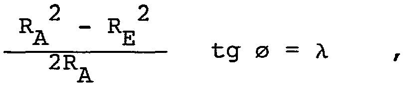
RA et RE étant respectivement, comme montré sur la figure 2a, les rayons du point (A) et du point (E) de l'armature de renfort (4) le plus éloigné axialement de la trace du plan équatorial (XX').RA and RE being respectively, as shown in FIG. 2a, the radii of point (A) and point (E) of the reinforcement reinforcement (4) most axially distant from the trace of the equatorial plane (XX ').
La jante (J) de montage des secteurs (S) de la première variante tels que décrits ci-dessus et montrés sur les fig 2a et 2b , comprend schématiquement (fig 6) un disque (D), un fond de jante (30), des sièges (31) et des rebords (32), ces rebords (32) ayant la particularité d'être discontinus circonférentiellement. Les évidements (33) ont les dimensions suivantes : la profondeur (a) est égale à la largeur axiale du rebord de jante et à 50 mm, soit sensiblement 0,06 d , d étant le diamètre du siège de jante ; la largeur circonférentielle (b) est égale à 28 mm, soit sensiblement 0,035 d ; la hauteur (h) d'un rebord de jante est égale à 50 mm.The rim (J) for mounting the sectors (S) of the first variant as described above and shown in fig 2a and 2b, schematically comprises (fig 6) a disc (D), a rim tape (30) , seats (31) and ledges (32), these ledges (32) having the distinction of being circumferentially discontinuous. The recesses (33) have the following dimensions: the depth (a) is equal to the axial width of the rim flange and 50 mm, ie substantially 0.06 d, d being the diameter of the rim seat; the circumferential width (b) is equal to 28 mm, ie substantially 0.035 d; the height (h) of a rim flange is equal to 50 mm.
Par comparaison à un ensemble formé du pneumatique et d'une jante à rebords dirigés vers l'axe de rotation du pneumatique, nous pouvons énoncer que nous sommes en présence d'un secteur à accrochage inversé, les bourrelets circonférentiels du secteur (S) renforcés par les tringles (10) venant se poser sur les sièges (31) de la jante (J) radialement par l'intérieur.By comparison with an assembly formed by the tire and a rim with flanges directed towards the axis of rotation of the tire, we can state that we are in the presence of a reverse latching sector, the circumferential beads of the sector (S) reinforced by the rods (10) coming to rest on the seats (31) of the rim (J) radially from the inside.
Le secteur pneumatique (S) représenté sur les figures 3a et 3b ne diffère fondamentalement de celui représenté sur les figures 2a et 2b que par la constitution des tringles renforçant les bourrelets du secteur.Les tringles circonférentielles (10) sont constituées de rubans (101) ou tubes d'acier laitonnés, retournés sur eux-mêmes radialement à l'intérieur, les retournements (102) étant eux-mêmes coudés de manière à ce que les rubans se terminent par des parties droites (103) cylindriques. Ces parties (103) sont filetées et permettent la fixation solide sur la jante de montage des secteurs (S), par le moyen d'écrous (34).The pneumatic sector (S) represented in FIGS. 3a and 3b differs fundamentally from that represented in FIGS. 2a and 2b only by the constitution of the rods reinforcing the beads of the sector. The circumferential rods (10) consist of ribbons (101) or brass-plated steel tubes, turned inside out radially inside, the turns (102) being themselves bent so that the ribbons end in straight cylindrical parts (103). These parts (103) are threaded and allow solid fixing to the mounting rim of the sectors (S), by means of nuts (34).
Quant à la jante (J) destinée à recevoir les secteurs (S) de la seconde variante tels que décrits ci-dessus et montrés sur les figures 3a et 3b , ses rebords (32) sont radialement à l'extérieur du fond de jante (30) et des sièges (31), (figure 3a), c'est-à-dire comme pour une jante normale.Les sièges (31) sont cependant percés d'orifices (33) destinés au passage des tiges filetées (103) correspondant aux tringles circonférentielles (10) ou "cavaliers". Les écrous (34) permettent la fixation solide, tout en étant simple.As for the rim (J) intended to receive the sectors (S) of the second variant as described above and shown in FIGS. 3a and 3b, its flanges (32) are radially outside the rim tape ( 30) and seats (31), (FIG. 3a), that is to say as for a normal rim. The seats (31) are however pierced with orifices (33) intended for the passage of the threaded rods (103) corresponding to the circumferential rods (10) or "jumpers". The nuts (34) allow the solid fixing, while being simple.
La troisième variante, montrée sur la figure 4, diffère des précédentes par le système d'accrochage à la jante (J) et par la jante (J) elle-même. Le système d'accrochage comprend une tringle (1) comprenant les parties circonférentielles (10) et les parties méridiennes -(11). Aux parties circonférentielles (10) sont adjointes deux portions de tringles (10') circulaires et maintenues fixées aux parties circonférentielles (10) par des colliers (10"). Autour de ce système est retournée l'armature de renfort (4) pour former des retournements (41). Un tel système d'accrochage permet l'emboîtage des bourrelets (6) dans la rainure d'accrochage (R) de la jante (J) formée d'une part par les sièges (31) de jante et les rebords arrondis (32) axialement vers l'intérieur, c'est-à-dire vers l'axe (XX').The third variant, shown in FIG. 4, differs from the previous ones by the system for attaching to the rim (J) and by the rim (J) itself. The attachment system comprises a rod (1) comprising the circumferential parts (10) and the meridian parts - (11). To the circumferential parts (10) are added two portions of circular rods (10 ′) and held fixed to the circumferential parts (10) by collars (10 "). Around this system the reinforcement reinforcement (4) is inverted to form such an attachment system allows the fitting of the beads (6) in the attachment groove (R) of the rim (J) formed on the one hand by the rim seats (31) and the rounded edges (32) axially inwards, that is to say towards the axis (XX ').
Sur la figure 5a, on voit les deux flancs (50), de deux secteurs (S) adjacents, qui se font face. L'un est muni d'une rainure (52), dont le tracé, vue sur le flanc (figure 5b) est une sinusoïde dont l'axe moyen (ZZ) est curviligne. L'autre est pourvu d'une saillie (53), présentant le même tracé sur le flanc que la rainure (52) sur le flanc qui fait face, et dont les dimensions sont telles que ladite saillie (53) s'emboîte parfaitement et sans effort dans la rainure (52).In Figure 5a, we see the two sides (50) of two adjacent sectors (S), which face each other. One is provided with a groove (52), the outline of which, seen on the side (FIG. 5b) is a sinusoid whose mean axis (ZZ) is curvilinear. The other is provided with a projection (53), having the same outline on the side as the groove (52) on the opposite side, and whose dimensions are such that said projection (53) fits perfectly and effortlessly in the groove (52).
Bien que les rainure et saillie ne soient représentées que dans la partie supérieure des flancs intersecteurs, il est évident que rainure et saillie peuvent être prolongées dans les parties latérales de ces flancs.Although the groove and projection are only shown in the upper part of the intersecting flanks, it is obvious that the groove and projection can be extended in the lateral parts of these flanks.
La figure 7a montre, très schématiquement un tambour de confection (T) destiné à la fabrication d'un secteur (S) muni d'une tringle unique (1). Ce tambour cylindrique a la particularité d'être muni de gorges (G), destinées à la pose et au serrage des tringles (1) sur le tambour, non circulaire mais ayant une configuration adaptée à celle de la tringle (1) du secteur (S). Ces gorges (G)- entourent une fenêtre (F), à l'intérieur de laquelle se trouve une membrane (M) déformable (figure 7b). Cette membrane (M) peut être renforcée en elle-même de manière à conférer sous l'effet de la pression de galbage la configuration désirée à l'armature de renfort, éventuellement l'armature de -carcasse --posée initialement sur le tambour (T). La membrane (M) peut aussi être déformée par l'action combinée de la pression de galbage et d'un support métallique situé radialement à l'intérieur de la membrane.FIG. 7a shows, very schematically, a construction drum (T) intended for the manufacture of a sector (S) provided with a single rod (1). This cylindrical drum has the particularity of being provided with grooves (G), intended for the installation and the tightening of the rods (1) on the drum, not circular but having a configuration adapted to that of the rod (1) of the sector ( S). These grooves (G) - surround a window (F), inside which is a deformable membrane (M) (Figure 7b). This membrane (M) can be reinforced in itself so as to impart under the effect of the curving pressure the desired configuration to the reinforcing reinforcement, possibly the carcass reinforcement - initially placed on the drum ( T). The membrane (M) can also be deformed by the combined action of the shaping pressure and a metal support located radially inside the membrane.
Le procédé pour fabriquer un secteur de pneumatique, donné à titre d'exemple, consiste à poser sur le tambour de confection, sommairement décrit ci-dessus, les gommes de protecteur de bourrelet, les nappes additionnelles éventuelles (7), l'armature éventuelle de câbles (5), les gommes de bourrage nécessaires, puis à galber l'ensemble ainsi constitué. L'armature de câbles radiaux (4) est alors posée avant le retournement autour des tringles (1) des nappes additionnelles (7). Le secteur est ensuite achevé par la pose des gommes de flanc, de la ou des couches de renforcement (8) de la bande de roulement (9). L'ébauche crue ainsi réalisée est ensuite vulcanisée dans un moule de cuisson de forme adaptée.The process for manufacturing a tire sector, given by way of example, consists in placing the bead protector gums, any additional plies (7), any reinforcement, on the garment drum, briefly described above. cables (5), the necessary stuffing rubber, then to bend the assembly thus formed. The armature of radial cables (4) is then laid before turning around the rods (1) of the additional plies (7). The sector is then completed by the installation of sidewall gums, of the reinforcing layer or layers (8) of the tread (9). The raw blank thus produced is then vulcanized in a baking mold of suitable shape.
Une deuxième technique possible de fabrication d'un secteur (S) consiste à utiliser un noyau dur, muni ou non d'espaceurs, sur lequel on dispose les éléments de renforcement de la nappe de renfort (4) et les éléments de renforcement de l'armature de carcasse (5), les nappes ou armature étant munies de leurs tringles respectives. Ce noyau est placé dans un moule adapté, dont la fermeture permet l'injection de matière caoutchouteuse.A second possible technique for manufacturing a sector (S) consists in using a hard core, whether or not provided with spacers, on which the reinforcing elements of the reinforcing ply (4) and the reinforcing elements of the 'carcass reinforcement (5), the plies or reinforcement being provided with their respective rods. This core is placed in a suitable mold, the closure of which allows the injection of rubbery material.
Quant aux chambres à air (C) nécessaires pour le gonflage des secteurs formant le pneumatique, lorsque ceux-çi ne sont pas munis intérieurement d'une couche de vulcanisat présentant la propriété d'être imperméable à l'air de gonflage, leur forme (figure 8) est pratiquement équivalente à la forme intérieure d'un secteur (S). Elles sont munies d'une valve (V) sur leur face plane (P) destinée à rentrer en contact avec la jante (J) de montage. Ces chambres sont fabriquées par rotomoulage c'est-à-dire en répartissant, par rotation simultanée selon trois axes, à l'intérieur d'un moule creux, un élastomère par exemple du polyuréthane à haute température pour effectuer la vulcanisation. As for the air chambers (C) necessary for the inflation of the sectors forming the tire, when these are not internally provided with a layer of vulcanizate having the property of being impermeable to the inflation air, their shape ( Figure 8) is practically equivalent to the interior shape of a sector (S). They are provided with a valve (V) on their flat face (P) intended to come into contact with the mounting rim (J). These chambers are manufactured by rotational molding, that is to say by distributing, by simultaneous rotation along three axes, inside a hollow mold, an elastomer, for example polyurethane at high temperature to effect vulcanization.
Claims (24)

Priority Applications (10)
| Application Number | Priority Date | Filing Date | Title |
|---|---|---|---|
| FR9202483A FR2687954A1 (en) | 1992-02-28 | 1992-02-28 | TIRE WITH SEVERAL INDEPENDENT REMOVABLE AND REINFORCED SECTORS. |
| CA002125297A CA2125297C (en) | 1992-02-28 | 1993-02-22 | Tire having a plurality of independant removable and reinforced sectors |
| ES93904002T ES2095635T3 (en) | 1992-02-28 | 1993-02-22 | TIRE WITH SEVERAL REMOVABLE AND REINFORCED INDEPENDENT SECTORS. |
| PCT/EP1993/000411 WO1993016890A1 (en) | 1992-02-28 | 1993-02-22 | Tyre having a plurality of independent removable and reinforced sectors |
| EP93904002A EP0627995B1 (en) | 1992-02-28 | 1993-02-22 | Tyre having a plurality of independent removable and reinforced sectors |
| DE69305627T DE69305627T2 (en) | 1992-02-28 | 1993-02-22 | TIRES WITH MULTIPLE INDEPENDENT, ADJUSTABLE AND REINFORCED SECTORS |
| AU34985/93A AU669880B2 (en) | 1992-02-28 | 1993-02-22 | Tyre having a plurality of independent removable and reinforced sectors |
| US08/284,615 US5556488A (en) | 1992-02-28 | 1993-02-22 | Tire having a plurality of independent removable and reinforced sectors |
| JP51453493A JP3431147B2 (en) | 1992-02-28 | 1993-02-22 | Removable and reinforced tires with multiple independent sectors |
| BR9305815A BR9305815A (en) | 1992-02-28 | 1993-02-22 | Pneumatic consisting of several inflatable and removable pneumatic sectors and set formed by the same and a rim |
Applications Claiming Priority (1)
| Application Number | Priority Date | Filing Date | Title |
|---|---|---|---|
| FR9202483A FR2687954A1 (en) | 1992-02-28 | 1992-02-28 | TIRE WITH SEVERAL INDEPENDENT REMOVABLE AND REINFORCED SECTORS. |
Publications (1)
| Publication Number | Publication Date |
|---|---|
| FR2687954A1 true FR2687954A1 (en) | 1993-09-03 |
Family
ID=9427257
Family Applications (1)
| Application Number | Title | Priority Date | Filing Date |
|---|---|---|---|
| FR9202483A Withdrawn FR2687954A1 (en) | 1992-02-28 | 1992-02-28 | TIRE WITH SEVERAL INDEPENDENT REMOVABLE AND REINFORCED SECTORS. |
Country Status (10)
| Country | Link |
|---|---|
| US (1) | US5556488A (en) |
| EP (1) | EP0627995B1 (en) |
| JP (1) | JP3431147B2 (en) |
| AU (1) | AU669880B2 (en) |
| BR (1) | BR9305815A (en) |
| CA (1) | CA2125297C (en) |
| DE (1) | DE69305627T2 (en) |
| ES (1) | ES2095635T3 (en) |
| FR (1) | FR2687954A1 (en) |
| WO (1) | WO1993016890A1 (en) |
Families Citing this family (11)
| Publication number | Priority date | Publication date | Assignee | Title |
|---|---|---|---|---|
| JP2003205703A (en) * | 1999-07-16 | 2003-07-22 | Toyoharu Maeda | Tire device, tire constituting method, and split tire element |
| US7182307B2 (en) * | 2003-09-30 | 2007-02-27 | Verti-Crete, Llc | System for vertically forming concrete panels |
| US8246002B1 (en) | 2003-09-30 | 2012-08-21 | Verti-Crete, Llc | Concrete panel mold having reinforced lower support gasket for vertically forming concrete panels |
| US20060137273A1 (en) * | 2005-12-12 | 2006-06-29 | Baker William B | Liner system for forming concrete panels |
| US7938158B2 (en) * | 2007-08-02 | 2011-05-10 | Bridgestone Americas Tire Operations, Llc | Puncture resistant pneumatic tire |
| US8141606B2 (en) | 2009-05-29 | 2012-03-27 | The Goodyear Tire & Rubber Company | Tire |
| US8662122B2 (en) | 2010-05-14 | 2014-03-04 | The Goodyear Tire & Rubber Company | System for non-pneumatic support of a vehicle |
| US9616713B2 (en) | 2010-08-30 | 2017-04-11 | The Goodyear Tire & Rubber Company | Non-pneumatic tire |
| US8720504B2 (en) | 2011-06-17 | 2014-05-13 | The Goodyear Tire & Rubber Company | System for non-pneumatic support of a vehicle |
| US9694629B1 (en) | 2012-02-29 | 2017-07-04 | Carolyn Dry | Self-repairing inflatable articles incorporating an integrated self-repair system |
| US8685513B1 (en) | 2012-02-29 | 2014-04-01 | Carolyn M. Dry | Inflatable articles comprising a self-repairing laminate |
Citations (5)
| Publication number | Priority date | Publication date | Assignee | Title |
|---|---|---|---|---|
| FR354950A (en) * | 1904-06-08 | 1905-10-18 | Frederick George Mckim | Pneumatic tire |
| FR380768A (en) * | 1907-08-12 | 1907-12-17 | Henry Delort | Severed pneumatic tire |
| GB191300457A (en) * | 1912-01-15 | 1913-03-13 | Morton Peabody Prince | Improvements in Sectional Pneumatic Tyres. |
| FR1529882A (en) * | 1967-05-11 | 1968-06-21 | Bertin & Cie | Inflatable roller more particularly intended for use as a running member for vehicles |
| US4153094A (en) * | 1977-02-28 | 1979-05-08 | Mckenzie Ross A | Sectional tire |
Family Cites Families (5)
| Publication number | Priority date | Publication date | Assignee | Title |
|---|---|---|---|---|
| US1322685A (en) * | 1919-11-25 | Vehicle-wheel | ||
| US1311806A (en) * | 1919-07-29 | Sectional pneumatic tire | ||
| US1104426A (en) * | 1912-04-02 | 1914-07-21 | Frederick Keller | Tire. |
| US1233853A (en) * | 1916-11-10 | 1917-07-17 | James Drummond | Pneumatic tire. |
| US2680464A (en) * | 1952-02-23 | 1954-06-08 | Est Ets Sciences Tec | Tire structure |
-
1992
- 1992-02-28 FR FR9202483A patent/FR2687954A1/en not_active Withdrawn
-
1993
- 1993-02-22 WO PCT/EP1993/000411 patent/WO1993016890A1/en active IP Right Grant
- 1993-02-22 CA CA002125297A patent/CA2125297C/en not_active Expired - Fee Related
- 1993-02-22 BR BR9305815A patent/BR9305815A/en not_active IP Right Cessation
- 1993-02-22 EP EP93904002A patent/EP0627995B1/en not_active Expired - Lifetime
- 1993-02-22 JP JP51453493A patent/JP3431147B2/en not_active Expired - Fee Related
- 1993-02-22 DE DE69305627T patent/DE69305627T2/en not_active Expired - Fee Related
- 1993-02-22 AU AU34985/93A patent/AU669880B2/en not_active Ceased
- 1993-02-22 US US08/284,615 patent/US5556488A/en not_active Expired - Lifetime
- 1993-02-22 ES ES93904002T patent/ES2095635T3/en not_active Expired - Lifetime
Patent Citations (5)
| Publication number | Priority date | Publication date | Assignee | Title |
|---|---|---|---|---|
| FR354950A (en) * | 1904-06-08 | 1905-10-18 | Frederick George Mckim | Pneumatic tire |
| FR380768A (en) * | 1907-08-12 | 1907-12-17 | Henry Delort | Severed pneumatic tire |
| GB191300457A (en) * | 1912-01-15 | 1913-03-13 | Morton Peabody Prince | Improvements in Sectional Pneumatic Tyres. |
| FR1529882A (en) * | 1967-05-11 | 1968-06-21 | Bertin & Cie | Inflatable roller more particularly intended for use as a running member for vehicles |
| US4153094A (en) * | 1977-02-28 | 1979-05-08 | Mckenzie Ross A | Sectional tire |
Also Published As
| Publication number | Publication date |
|---|---|
| DE69305627D1 (en) | 1996-11-28 |
| EP0627995A1 (en) | 1994-12-14 |
| US5556488A (en) | 1996-09-17 |
| AU3498593A (en) | 1993-09-13 |
| EP0627995B1 (en) | 1996-10-23 |
| BR9305815A (en) | 1997-02-18 |
| ES2095635T3 (en) | 1997-02-16 |
| CA2125297A1 (en) | 1993-09-02 |
| AU669880B2 (en) | 1996-06-27 |
| WO1993016890A1 (en) | 1993-09-02 |
| DE69305627T2 (en) | 1997-03-06 |
| CA2125297C (en) | 2004-02-17 |
| JP3431147B2 (en) | 2003-07-28 |
| JPH07504139A (en) | 1995-05-11 |
Similar Documents
| Publication | Publication Date | Title |
|---|---|---|
| EP0733000B1 (en) | Tyre, rim, supporting ring and assembly comprising same | |
| EP2209655B1 (en) | Tyre with shell and carrier structure | |
| EP0748287B1 (en) | Tyre with beads having an improved structure, and assembly of said tyre and a suitable rim | |
| EP0627995B1 (en) | Tyre having a plurality of independent removable and reinforced sectors | |
| FR2776238A1 (en) | Tire with bead reinforcements designed for use on heavy vehicles | |
| CA2127433C (en) | Holding device of the tread of a tire | |
| EP1047565A1 (en) | Tyre bead with circumferential reinforcing elements | |
| EP1289779B1 (en) | Tyre comprising a reinforcing profiled section in at least one sidewall, and mounted tyre/rim assembly | |
| EP1353811B1 (en) | Tyre with additional ring | |
| EP0626279B1 (en) | Sealing ring between tire beads | |
| EP1257427B1 (en) | Tyre bead | |
| EP0835769B9 (en) | Supporting device for tyre tread | |
| WO2002051651A1 (en) | Assembly consisting of a tyre and a sealing component and method for making same | |
| FR2773517A1 (en) | TIRE SADDLE WITH CIRCUMFERENTIAL REINFORCEMENT ELEMENTS | |
| WO1998023457A1 (en) | Supporting membrane for tyre tread | |
| EP1185426B1 (en) | Coreless bead for tyre | |
| FR2610872A1 (en) | VEHICLE WHEEL WITH OPERATING SAFETY CHARACTERISTICS IN THE EVENT OF AN AVIATION | |
| EP3642051A1 (en) | Tyre type device for vehicle | |
| FR2781723A1 (en) | RADIAL TIRE SADDLE | |
| LU86479A1 (en) | PNEUMATIC BANDAGES | |
| FR2903047A1 (en) | Running flat device for motor vehicle, has textile wall delimiting annular compartment with locking units, and support portion with circumferential support unit on its inner side for taking back force applied to support unit by flanges | |
| EP3642052A1 (en) | Tyre type device for vehicle | |
| LU86064A1 (en) | PNEUMATIC TAPE WITH CONCAVED SIDES |
Legal Events
| Date | Code | Title | Description |
|---|---|---|---|
| ST | Notification of lapse |