EP2422862A1 - Abscheider zum Trennen eines Ein- oder Mehrphasengemisches - Google Patents
Abscheider zum Trennen eines Ein- oder Mehrphasengemisches Download PDFInfo
- Publication number
- EP2422862A1 EP2422862A1 EP10174002A EP10174002A EP2422862A1 EP 2422862 A1 EP2422862 A1 EP 2422862A1 EP 10174002 A EP10174002 A EP 10174002A EP 10174002 A EP10174002 A EP 10174002A EP 2422862 A1 EP2422862 A1 EP 2422862A1
- Authority
- EP
- European Patent Office
- Prior art keywords
- separator
- mixture
- light liquid
- collector
- wall
- Prior art date
- Legal status (The legal status is an assumption and is not a legal conclusion. Google has not performed a legal analysis and makes no representation as to the accuracy of the status listed.)
- Granted
Links
Images


Classifications
-
- B—PERFORMING OPERATIONS; TRANSPORTING
- B01—PHYSICAL OR CHEMICAL PROCESSES OR APPARATUS IN GENERAL
- B01D—SEPARATION
- B01D17/00—Separation of liquids, not provided for elsewhere, e.g. by thermal diffusion
- B01D17/02—Separation of non-miscible liquids
- B01D17/0208—Separation of non-miscible liquids by sedimentation
- B01D17/0211—Separation of non-miscible liquids by sedimentation with baffles
-
- B—PERFORMING OPERATIONS; TRANSPORTING
- B01—PHYSICAL OR CHEMICAL PROCESSES OR APPARATUS IN GENERAL
- B01D—SEPARATION
- B01D17/00—Separation of liquids, not provided for elsewhere, e.g. by thermal diffusion
- B01D17/02—Separation of non-miscible liquids
- B01D17/0217—Separation of non-miscible liquids by centrifugal force
-
- B—PERFORMING OPERATIONS; TRANSPORTING
- B01—PHYSICAL OR CHEMICAL PROCESSES OR APPARATUS IN GENERAL
- B01D—SEPARATION
- B01D21/00—Separation of suspended solid particles from liquids by sedimentation
- B01D21/003—Sedimentation tanks provided with a plurality of compartments separated by a partition wall
-
- B—PERFORMING OPERATIONS; TRANSPORTING
- B01—PHYSICAL OR CHEMICAL PROCESSES OR APPARATUS IN GENERAL
- B01D—SEPARATION
- B01D21/00—Separation of suspended solid particles from liquids by sedimentation
- B01D21/0039—Settling tanks provided with contact surfaces, e.g. baffles, particles
- B01D21/0042—Baffles or guide plates
-
- B—PERFORMING OPERATIONS; TRANSPORTING
- B01—PHYSICAL OR CHEMICAL PROCESSES OR APPARATUS IN GENERAL
- B01D—SEPARATION
- B01D21/00—Separation of suspended solid particles from liquids by sedimentation
- B01D21/0039—Settling tanks provided with contact surfaces, e.g. baffles, particles
- B01D21/0054—Plates in form of a coil
-
- B—PERFORMING OPERATIONS; TRANSPORTING
- B01—PHYSICAL OR CHEMICAL PROCESSES OR APPARATUS IN GENERAL
- B01D—SEPARATION
- B01D21/00—Separation of suspended solid particles from liquids by sedimentation
- B01D21/24—Feed or discharge mechanisms for settling tanks
- B01D21/2427—The feed or discharge opening located at a distant position from the side walls
-
- B—PERFORMING OPERATIONS; TRANSPORTING
- B01—PHYSICAL OR CHEMICAL PROCESSES OR APPARATUS IN GENERAL
- B01D—SEPARATION
- B01D21/00—Separation of suspended solid particles from liquids by sedimentation
- B01D21/24—Feed or discharge mechanisms for settling tanks
- B01D21/2433—Discharge mechanisms for floating particles
-
- B—PERFORMING OPERATIONS; TRANSPORTING
- B01—PHYSICAL OR CHEMICAL PROCESSES OR APPARATUS IN GENERAL
- B01D—SEPARATION
- B01D21/00—Separation of suspended solid particles from liquids by sedimentation
- B01D21/24—Feed or discharge mechanisms for settling tanks
- B01D21/245—Discharge mechanisms for the sediments
-
- B—PERFORMING OPERATIONS; TRANSPORTING
- B01—PHYSICAL OR CHEMICAL PROCESSES OR APPARATUS IN GENERAL
- B01D—SEPARATION
- B01D21/00—Separation of suspended solid particles from liquids by sedimentation
- B01D21/26—Separation of sediment aided by centrifugal force or centripetal force
- B01D21/265—Separation of sediment aided by centrifugal force or centripetal force by using a vortex inducer or vortex guide, e.g. coil
-
- B—PERFORMING OPERATIONS; TRANSPORTING
- B01—PHYSICAL OR CHEMICAL PROCESSES OR APPARATUS IN GENERAL
- B01D—SEPARATION
- B01D21/00—Separation of suspended solid particles from liquids by sedimentation
- B01D21/30—Control equipment
- B01D21/34—Controlling the feed distribution; Controlling the liquid level ; Control of process parameters
Definitions
- the present invention generally relates to a separator. Specifically, the invention relates to a separator for separating a single or multi-phase mixture. , in particular a proportion of light liquid and a portion of sludge, or a single-phase mixture of a smaller proportion of light liquid and a larger proportion of heavy liquid, such as oil-contaminated and possibly sludge-conducting water.
- a spiral separator for oil and sludge which has a separating basin for collecting the light liquid and possibly the sludge, a feed pipe for the mixture to be separated and a drain pipe for heavy liquid and possibly of sludge largely freed heavy liquid.
- the separating basin is designed such that liquid contains at least up to a lowest liquid level predetermined by a drainage threshold from the separating basin to the drainage pipe.
- the separator further comprises a disposed within the separating basin light liquid collector having a substantially tubular vertical wall.
- the wall of the collector as well as the partition wall each have an upper edge which is higher, at least in the region of the outermost space than the lowest liquid level. Furthermore, should - according to the EP 0 960 643 A1 - The inlet pipe through the wall of the collector and approximately tangentially open into the outermost space of the collector and the outermost space should have at least in the region of an inlet mouth of the inlet pipe a horizontal-radial clear width, which corresponds approximately to a horizontal width of the inlet pipe.
- the separator is the EP 0 960 643 A1 less suitable for separating a two- or three-phase mixture in which one phase consists, for example, of sand or smaller rock oil.
- the object of the invention is to improve the generic separator on.
- the separator should be capable of separating a two- or three-phase mixture in which one phase, e.g. consists of particles, sand and / or settleable substances.
- the separating basin is funnel-shaped at least in the lower region.
- the inner spiral of the spiral-like gap extends far into the funnel-shaped Schlammabsetzraum until close to the sludge removal system.
- the measures of the invention initially have the consequence that the drainage values and the separation of oil and particles are improved by the funnel-shaped design of the spiral walls and the entire built-in part.
- the Schlammabsetzraum is disposed below the mixture separator and light liquid collector, wherein the inner turn of the partition is guided just deeper into the separation basin than the outer turn.
- the improvements are particularly effective when separating a two-phase mixture with a proportion of light liquid and a proportion of sludge, but also in the separation of single-phase mixture with a smaller proportion of light liquid and a greater proportion of heavy liquid, such as oil-contaminated and optionally sludge leading water.
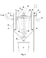
- FIG. 1 Illustrated u training example of an inventive separator is intended for collecting light liquid and possibly sludge, which - usually - smaller amount in a larger amount of heavy liquid - usually Wasswer - contain and be carried along.
- the separator comprises a separating basin 12 with a feed pipe 14 for the supply of the mixture to be separated and a discharge pipe 16 for the discharge of the heavy liquid (for example oil) and possibly of the sludge largely freed heavy liquid (for example water).
- the inlet pipe 14 and the drain pipe 16 are substantially diametrically opposed to each other at the substantially hollow cylindrical in the upper part with a vertical axis and tapered downwards in the lower part arranged.
- the drain threshold 18 determines by its height (not shown) lowest level of liquid in the separation tank 12th
- a planar partition wall 4 is arranged, which, starting from the wall 3 of the collector 20, substantially rolls up to the axis of the collector 20 with spiral-like turns. More precisely, the partition wall 4 is substantially shaped as a section of a surface resulting from a generatrix 32 and a spiral-like guide curve. Successive turns of the partition wall 4 define with each other a vertical spiral-like gap, while an outermost turn of the partition wall 4 together with the wall 3 of the collector 20 defines an outermost gap of the collector 20, in which the inlet pipe 14 opens. Accordingly, the outermost intermediate space of the collector 20 in the region of an inlet mouth 70 of the inlet pipe 14 with a transition piece to improve the flow on a horizontal-radial clear width, which corresponds approximately to the horizontal width of the inlet pipe 14 itself.
- the upper edge of the wall 3 of the collector 20 is higher than that of the drain threshold 18 certain highest liquid level.
- the exhaust pipe 46 may also be designed to be flexible or extendable and arranged on a float provided for floating on the liquid in such a way that the upper opening 58 of the exhaust pipe is always near the liquid level on the axis of the collector 20.
- connection for returning liquid to the collector.
- This compound can be formed, for example, as a small hole with a connected line in the upper part of the baffle and essentially serves to make the weight differences caused by differences in differences in the liquid levels in the various parts of the system to the very last floated particles and droplets etc Of light liquid from the emerging heavy liquid to remove and return to the collector.
- the trigger of the light liquid is - as in FIG. 3 shown here on the basic example of the non-conical configuration of the spiral partition, but of course also on the improved design of the conical configuration used - no ⁇ labschreibraum provided, but designed as a tube light liquid withdrawal (oil drain) in a light liquid container (oil tank) with an upper valve for the Collected light liquid (oil) and a lower valve for a possibly to be supplied to another separator rest.
- the partition on its outwardly facing side coated with a light-rejecting material, coated or painted, while the partition wall and the wall 3 of the collector 20 on its inwardly facing sides with a readily wettable by the light liquid material coated, coated or painted.
- the light-rejecting material may be an oil-repellent polymer
- the material wettable by the light-weight liquid may be, for example, an oil-friendly polymer such as polyamide or the like.
- the separator was designed to optimally separate oils and at the same time, and especially, settleable substances in the ⁇ m range.
- Light liquids with the specific gravity of 0.85 flow automatically at an oil level of 12 cm, which forms quickly in the upper part in the middle. They are by the central bulge with Abdrückrohr outside the flow area, so are no longer entrained. Settleable substances are withdrawn with a minimum amount of wastewater at the bottom and then sent for further treatment.
- Fine particles in the range below 50 microns remain in the centrifugal movement on the spiral outer wall until the second revolution - ie 720 ° - and are directed into the third revolution circle. Here they are separated from the flow path of the main stream and only exposed to the suction of the suction pump connected to the funnel and are further promoted and discharged with the coarser substances that have fallen through the main flow for bypass treatment.
- the drainage threshold which circulates the entire separation chamber favors the calm and uniform outflow of the heavy liquid and, associated therewith, a very good cleaning performance of light liquids and in particular of settable solids.
Landscapes
- Chemical & Material Sciences (AREA)
- Chemical Kinetics & Catalysis (AREA)
- Physics & Mathematics (AREA)
- Thermal Sciences (AREA)
- Removal Of Floating Material (AREA)
Abstract
Description
- Die vorliegende Erfindung betrifft allgemein einen Abscheider. Speziell betrifft die Erfindung einen Abscheider zum Trennen eines Ein- oder Mehrphasengemisches. , insbesondere eines Anteils Leichtflüssigkeit und eines Anteils Schlamm, oder eines Einphasengemisches eines kleineren Anteils Leichtflüssigkeit und eines grösseren Anteils Schwerflüssigkeit, wie ölverschmutztes und gegebenenfalls Schlamm führendes Wasser.
- Aus der
EP 0 960 643 A1 ist ein Spiralabscheider für Öl und Schlamm bekannt, das ein Abscheidebecken zum Auffangen der Leichtflüssigkeit und ggf. des Schlammes, einem Zulaufrohr für das zu trennende Gemisch und einem Ablaufrohr für von Leichtflüssigkeit und ggf. von Schlamm weitgehend befreite Schwerflüssigkeit aufweist. Das Abscheidebecken ist so ausgebildet ist, dass Flüssigkeit zumindest bis zu einem von einer Ablaufschwelle vom Abscheidebecken zum Ablaufrohr hin vorgegebenen niedrigsten Flüssigkeitsspiegel enthält. Der Abscheider weist weiterhin einen innerhalb des Abscheidebeckens angeordneten Leichtflüssigkeit-Sammler mit einer im Wesentlichen rohrförmige vertikale Wandung aufweist. Bei dem Abscheider derEP 0 960 643 A1 gelangt das Gemisch vom Zulaufrohr zum Inneren des Sammlers und aus einem unteren Bereich des Sammlers gelangt Schwerflüssigkeit und ggf. Schlamm zu einem unteren Bereich des Abscheidebeckens hin. Innerhalb des Sammlers ist eine Trennwand angeordnet, die im Wesentlichen als Ausschnitt einer Regelfläche geformt ist. Die Trennwand ergibt sich aus vertikalen Erzeugenden und einer horizontalen spiralartigen Leitkurve und rollt sich ausgehend von der Wandung des Sammlers im Wesentlichen bis zur Achse des Sammlers mit spiralartigen Windungen ein. Aufeinanderfolgende Windungen der Trennwand definieren miteinander einen spiralartigen Zwischenraum, während eine äusserste Windung der Trennwand zusammen mit der Wandung des Sammlers einen äussersten Zwischenraum definiert. Gemäss derEP 0 960 643 A1 soll sowohl die Wandung des Sammlers wie auch die Trennwand je einen oberen Rand aufweisen, der zumindest im Bereich des äussersten Zwischenraumes höher liegt als der niedrigste Flüssigkeitsspiegel. Weiterhin soll - gemäss derEP 0 960 643 A1 - das Zulaufrohr durch die Wandung des Sammlers hindurch und annähernd tangential dazu in den äussersten Zwischenraum des Sammlers einmünden und der äusserste Zwischenraum soll zumindest im Bereich einer Eintrittsmündung des Zulaufrohres eine horizontal-radiale lichte Weite aufweisen, die annähernd einer horizontalen Weite des Zulaufrohres entspricht. Allerdings ist der Abscheider derEP 0 960 643 A1 weniger geeignet, ein Zwei- oder Dreiphasengemisch zu trennen, bei dem eine Phase z.B. aus Sand oder kleinerem Steingeröll besteht. - Aufgabe der Erfindung ist es, den gattungsgemässen Abscheider weiter zu verbessern. Insbesondere soll der Abscheider gemäss der Aufgabe der Erfindung geeignet sein, ein Zwei- oder Dreiphasengemisch zu trennen, bei dem eine Phase z.B. aus Partikeln, Sand und/oder absetzbaren Stoffen besteht.
- Diese Aufgabe wird durch einen Abscheider nach Anspruch 1 gelöst. Erfindungsgemäss ist das Abscheidebecken zumindest im unteren Bereich trichterförmig ausgebildet. Die innere Spirale des spiralartigen Zwischenraums zieht sich bis weit in den trichterförmig ausgebildeten Schlammabsetzraum bis nahe bis an das Schlammabzugssystem hin. Dabei haben die Massnahmen der Erfindung zunächst einmal zur Folge, dass durch die trichterförmige Ausbildung der Spiralwände und des gesamten Einbauteils die Ablaufwerte und die Trennung von Öl und Partikeln verbessert werden. Der Schlammabsetzraum ist unter dem Gemischtrenner und Leichtflüssigkeitssammler angeordnet, wobei die innere Windung der Trennwand eben tiefer in das Abscheidebecken geführt ist als die äussere Windung.
Die Verbesserungen wirken sich insbesondere beim Trennen eines Zweiphasengemisches mit einem Anteil Leichtflüssigkeit und einem Anteil Schlamm aus, aber auch bei der Trennung Einphasengemisches mit einem kleineren Anteil Leichtflüssigkeit und einem grösseren Anteil Schwerflüssigkeit, wie ölverschmutztes und gegebenenfalls Schlamm führendes Wasser. - Als besonders vorteilhaft hat sich herausgestellt, wenn die die Windungen der Trennwand konisch angeordnet sind derart, dass die unteren Bereiche der Trennwand jeweils einen kleineren Spiralradius aufweisen als die obere Bereiche.
- Es ist bekannt, dass sich bei dem Abscheider gemäss dem Stand der Technik nach ca. 100 - 120° Umdrehung sich im Wirbelweg strömungstechnisch eine Spreizung des Stromes um ca. 30 - 45° nach oben und unten ausbildet. Diese wird aufgehoben durch ein nach 120° Strömung eingelassenes, sogenanntes 3x 6 geteiltes Rohrbogenpaket. Das Gleiche wird nach Ausgang des ersten Paketes im Bereich der folgenden 100 - 120° Umdrehung ebenfalls eingelassen. Diese 3x 6 geteilten Rohrbogenpakete gewährleisten eine waagerecht geführte Strömung und man erreicht eine ruhigere Oberfläche und ruhigere und intensivierte - für Partikel auswirkende zentrifugale und für Leichtstoffe auswirkende zentripetale - Mechanismen. Damit wird eine wesentlich begünstigte Öl- und Partikelseparierung erreicht, in dem der notwendige Weg zur Mitte verbessert wird. Mit dieser Entwicklung ist eine verbesserte Reinigungsleistung von Ölabscheidung und Partikelseparierung im Galaxie-Wirbelsystem erreicht worden.
- Besonders vorteilhafte Ausführungen sind in den abhängigen Patentansprüchen angegeben.
-
- Fig. 1
- eine schematische Darstellung eines ersten Ausführungsbeispiels eines erfindungsgemässen Abscheiders, im mit einer vertikalen, nichtkonischen Ausbildung der spiralförmigen Trennwände;
- Figur 2
- eine schematische Darstellung eines zweiten Ausführungsbeispiels eines erfindungsgemässen Abscheiders, im mit einer konischen Ausbildung der spiralförmigen Trennwände;
- Figur 3
- eine schematische Darstellung mit einer alternativen Ausgestaltung des Ölabzuges mit einer vertikalen, nichtkonischen Ausbildung der spiralförmigen Trennwände gemäss
Figur 1 ; und - Figur 4
- eine schematische Darstellung mit einer alternativen Ausgestaltung des Schlammabzuges mit einem Auslauf in einen Siebcontainer mit einer konischen Ausbildung der spiralförmigen Trennwände gemäss
Figur 2 . - Das hier dargestellte Ausführungsbeispiel entspricht dem im Stand der Technik dargestellten, soweit es durch die speziellen Massnahmen der Erfindung nicht abgewandelt ist. Daher wird hier auf den in der
EP 0 960 643 A1 dargestellten Beschreibungstext zunächst einmal zurückgegriffen, um die Grundversion zu beschreiben. - Ein in
Fig. 1 dargestelltes u Ausbildungsbeispiel eines erfindungsgemässen Abscheiders ist zum Auffangen von Leichtflüssigkeit und ggf. Schlamm bestimmt, die als -üblicherweise - kleinere Menge in einer grösseren Menge Schwerflüssigkeit - üblicherweise Wasswer - enthalten und davon mitgeführt werden. - Der Abscheider umfasst ein Abscheidebecken 12 mit einem Zulaufrohr 14 für die Zuleitung des zu trennenden Gemisches und einem Ablaufrohr 16 für die Ableitung der von der Leichtflüssigkeit (beispielsweise Öl) und ggf. vom Schlamm weitgehend befreite Schwerflüssigkeit (beispielsweise Wasser). Das Zulaufrohr 14 und das Ablaufrohr 16 sind am dem im oberen Teil im Wesentlichen hohlzylindrisch mit vertikaler Achse und im unteren Teil nach unten konisch verjüngt ausgebildeten Abscheidebecken 12 im Wesentlichen diametral einander gegenüberliegend angeordnet. Die Ablaufschwelle 18 bestimmt durch ihre Höhe einen (nicht näher dargestellten) niedrigsten Flüssigkeitsspiegel im Abscheidebecken 12.
- Im Abscheidebecken 12 ist ein Gemischtrenner und Leichtflüssigkeit-Sammler 20 angeordnet, der eine rohrförmige Wandung 3 um eine im wesentlichen vertikalen Achse aufweist. Vom Zulaufrohr 14 gelangt das Gemisch zum Inneren des Sammlers 20, indem das Zulaufrohr 14 durch die Wandung 3 des Sammlers 20 hindurch und annähernd tangential dazu in den Sammler 20 einmündet. Aus einem unteren Bereich des Sammlers 20 gelangt Schwerflüssigkeit und ggf. Schlamm zu einem unteren Bereich 28 des Abscheidebeckens 12, der zweckmässigerweise als Schlammfangraum ausgebildet ist.
- Innerhalb des Sammlers 20 ist eine flächige Trennwand 4 angeordnet, die sich, ausgehend von der Wandung 3 des Sammlers 20, im Wesentlichen bis zur Achse des Sammlers 20 mit spiralartigen Windungen einrollt. Präziser ausgedrückt ist die Trennwand 4 im Wesentlichen als Ausschnitt einer Fläche geformt, welche sich aus einer Erzeugenden 32 und einer spiralartigen Leitkurve ergibt. Aufeinanderfolgende Windungen der Trennwand 4 definieren miteinander einen vertikalen spiralartigen Zwischenraum, während eine äusserste Windung der Trennwand 4 zusammen mit der Wandung 3 des Sammlers 20 einen äussersten Zwischenraum des Sammlers 20 definiert, in welchen das Zulaufrohr 14 einmündet. Dementsprechend weist der äusserste Zwischenraum des Sammlers 20 im Bereich einer Eintrittsmündung 70 des Zulaufrohres 14 mit einem Übergangsstück zur Strömungsverbesserung eine horizontal-radiale lichte Weite auf, die annähernd der horizontalen Weite des Zulaufrohres 14 selbst entspricht.
- Der obere Rand der Wandung 3 des Sammlers 20 liegt höher als der von der Ablaufschwelle 18 bestimmte höchste Flüssigkeitsspiegel.
- In
Figur 3 dargestellt ist mittig-axial im Sammler 20 ein Abzugsrohr 46 angeordnet, dessen obere Öffnung etwa auf Höhe des niedrigsten Flüssigkeitsspiegels liegt. Dieses Abzugsrohr 46 führt zu einem Ölabdruckbehälter 48, der Öle speichert und auf den kleinen Wasserablauf 68 einen Sog ausübt und über ein Ölabdrückrohr 58, das höher liegt als der maximale Betriebswasserstand im Abscheider bei einem bestimmten Ölstand das Öl überlaufen lässt. - Das Abzugsrohr 46 kann auch den ist flexibel oder ausziehbar ausgebildet sein und an einem zum Schwimmen auf der Flüssigkeit vorgesehenen Schwimmkörper auf solche Weise angeordnet sein, dass sich die obere Öffnung 58 des Abzugsrohres stets unweit des Flüssigkeitsspiegels auf der Achse des Sammlers 20 befindet.
- Es kann eine (nicht dargestellte) Verbindung zum Rückführen von Flüssigkeit zum Sammler vorgesehen werden. Diese Verbindung kann beispielsweise als kleines Loch mit angeschlossener Leitung im oberen Teil der Tauchwand ausgebildet sein und dient im wesentlichen dazu, die von den Wichte-Unterschieden bewirkten Unterschiede der Flüssigkeitsspiegel in den verschiedenen Teilen der Anlage zu nutzen, um die allerletzten aufgeschwommenen Partikel und Tröpfchen etc. von Leichtflüssigkeit aus der austretenden Schwerflüssigkeit zu entfernen und zum Sammler zurückzuführen.
- Um die Koaleszenz der aufgeschwommenen Partikel und Tröpfchen etc. der Leichtflüssigkeit zu fördern, ist die Trennwand auf ihren beiden Oberflächen d.h. auf ihren beiden vertikalen Seiten mit verschiedener Beschaffenheit ausgebildet. Auf der nach aussen gewandten Seite ihrer Windungen ist die Trennwand 4 von der Leichtflüssigkeit weniger benetzbar ausgebildet als auf der nach innen gewandten Seite ihrer Windungen.
- In einem verbesserten Ausführungsbeispiel sind - wie in
Figur 2 dargestellt - die Windungen der spiralförmigen Trennwand 4 konisch angeordnet derart, dass die unteren Bereiche der Trennwand jeweils einen kleineren Spiralradius aufweisen als die obere Bereiche. Durch diese Geometrie lässt sich - wie sich gezeigt hat - eine verbesserte Trennung von Schlamm, Leichtflüssigkeit und Schwerflüssigkeit erzielen. - In einer alternativen Ausführung des Abzugs der Leichtflüssigkeit ist - wie in
Figur 3 hier am Grundbeispiel der nichtkonischen Ausgestaltung der spiralförmigen Trennwand dargestellt, aber selbstverständlich auch an der verbesserten Ausführung der konischen Ausgestaltung einsetzbar - kein Ölabrückraum vorgesehen, sondern ein als Rohr ausgestalteter Leichtflüssigkeitsabzug (Ölabzug), der in einen Leichtflüssigkeitsbehälter (Ölbehälter) mit einem oberen Ventil für die gesammelte Leichtflüssigkeit (Öl) und einem unteren Ventil für ein allenfalls einem weiteren Abscheider zuzuführenden Rest. - Zur Erzeugung der gewünschten Oberflächenbeschaffenheit kann die Trennwand auf ihrer nach aussen gewandten Seite mit einem die Leichtflüssigkeit abweisenden Material überzogen, beschichtet oder gestrichen, während die Trennwand sowie die Wandung 3 des Sammlers 20 auf ihrer nach innen gewandten Seiten mit einem von der Leichtflüssigkeit gut benetzbaren Material überzogen, beschichtet oder gestrichen sind. Beispielsweise kann das die Leichtflüssigkeit abweisende Material ein ölabweisendes Polymer sein, während das von der Leichtflüssigkeit benetzbare Material beispielsweise ein ölfreundliches bzw. ölfreundlicheres Polymer wie Polyamid oder dergleichen sein kann.
- Der Abscheider wurde konzipiert, um Öle und zugleich und insbesondere, absetzbare Stoffe im µm-Bereich optimal zu separieren. Leichtflüssigkeiten mit dem spezifischen Gewicht von 0,85 fliessen bei einem Ölstand von 12 cm, der sich schnell im oberen Teil mittig ausbildet, automatisch über. Sie sind durch die mittige Aufwölbung mit Abdrückrohr ausserhalb des Strömungsbereiches, werden also nicht mehr mitgerissen. Absetzbare Stoffe werden mit einem minimalen Abwasseranteil unten abgezogen und dann einer weiteren Behandlung zugeführt.
- Durch Testreihen konnte gezeigt werden, dass sich die Feinstpartikel nach 360° gebündelt wie ein Film an der äusseren Wand der Spirale entlang zur Mitte bewegen. Die Spirale hat unterschiedliche Längen. Die ca. 360° rohrähnliche Mitte der Spirale ist am längsten und zwar bis ca. 50 mm über der Absaugpumpe ausgebildet. Grössere Partikel und Metall- oder Stein-Stücke fallen in der ersten 360° Umdrehung automatisch nach unten - auch durch den waagrecht, dann nach oben bewegenden Hauptstrom hindurch. Feinere Partikel erreichen die zweite Umdrehung von 360° und können durch die tiefer ausgebildete Spiralwand tiefer unten im Kreislauf der zweiten Spirale gehalten werden, wo die waagrechte Strömung geringer ist. Sie fallen deshalb durch die langsamere Strömung in die Trichterspitze. Feinstpartikel im Bereich unter 50 µm bleiben bis zur zweiten Umdrehung - also 720° - in der zentrifugalen Bewegung an der Spiralaussenwand und werden in den dritten Umdrehungskreis geleitet. Hier sind sie vom Strömungsweg des Hauptstromes abgegrenzt und nur noch dem Sog der am Trichter angeschlossenen Saugpumpe ausgesetzt und werden mit den durch den Hauptstrom durchgefallenen gröberen Stoffen zur Bypassbehandlung weitergefördert und ausgeschleust.
- Die den gesamten Abscheideraum umlaufende Ablaufschwelle begünstigt dabei die beruhigte und gleichmässige Ablaufströmung der Schwerflüssigkeit und damit verbunden eine sehr gute Reinigungsleistung von Leichtflüssigkeiten und insbesondere von absetzbaren Feiststoffen.
-
- 1
- Zulauf
- 2
- Aussenwand des Abscheiders
- 3
- rohrförmige Wandung des Sammlers
- 4
- spiralförmige Trennwand
- 6
- unterer Bereich des Sammlers
- 12
- Abscheidebecken
- 14
- Zulaufrohr
- 16
- Ablaufrohr für Schwerflüssigkeit/Wasser
- 18
- Ablaufschwelle
- 20
- Gemischtrenner und Leichtflüssigkeitssammler
- 28
- unterer, vorzugsweise trichterförmiger Bereich des Abscheidebeckens, Schlammabsetzraum
- 32
- Erzeugende
- 38
- oberer Rand der Wandung des Sammlers
- 46
- Abzugsrohr
- 48
- Ölabdrückraum
- 50
- Ölablaufrohr
- 54
- Austrittsmündung des Ablaufrohres
- 58
- Überlauf zum Ölabdrückraum
- 60a, 60b
- Ölablaufkanal
- 68
- kleiner Wasserablauf
- 70
- Eintrittsmündung mit Übergangsstück zur Strömungsverbesserung
- B
- Schlammabzugsystem
- C
- Siebcontainer
Claims (12)
- Abscheider zum Trennen eines Ein- oder Mehrphasengemisches,mit einem Abscheidebecken (12) zum Auffangen einer Leichtflüssigkeit und gegebenenfalls eines Schlammes, einem Zulaufrohr (14) für das zu trennende Gemisch und einem Ablaufrohr (16) für eine von Leichtflüssigkeit und gegebenenfalls von Schlamm weitgehend befreite Schwerflüssigkeit,wobei das Abscheidebecken (12) einen innerhalb des Abscheidebeckens (12) angeordneten Gemischtrenners und Leichtflüssigkeitssammlers (20), der eine rohrförmige Wandung (3) aufweist,wobei der Abscheider (12) so ausgebildet ist, dass das Gemisch vom Zulaufrohr (14) in den Gemischtrenner und Leichtflüssigkeitssammler (20) gelangt und aus einem unteren Bereich des Gemischtrenners und Leichtflüssigkeitssammlers (20) Schwerflüssigkeit und gegebenenfalls davon getrennt Schlamm in den unteren Bereich des Abscheidebeckens (12) hin gelangt,wobei innerhalb des Gemischtrenner und -Leichtflüssigkeitssammlers (20) eine Trennwand (4) angeordnet ist, die sich, ausgehend von der Wandung (3) des Gemischtrenners und Leichtflüssigkeitssammlers (20) in Richtung Achse des Gemischtrenners und Leichtflüssigkeitssammlers (20) einrollt und mit nahezu einer oder aufeinanderfolgenden Windungen der Trennwand (4) miteinander einen spiralartigen Zwischenraum definiert, während eine äussere Windung der Trennwand (4) einen äussersten Zwischenraum definiert,dadurch gekennzeichnet, dass
der Abscheider im unteren Bereich ein Schlammabzugssystem (B) oder ein Ventil zum Ablassen von Schlamm aufweist,
sich die innere Spirale des spiralartigen Zwischenraums bis weit in den unteren Bereich des Abscheidebeckens (12) bis nahe bis an das Schlammabzugssystem (B) hinzieht, wobei die innere Windung der Trennwand (4) tiefer in das Abscheidebecken (12) geführt ist als die äussere Windung. - Abscheider nach Anspruch 1, dadurch gekennzeichnet, dass das Abscheidebecken (12) zumindest im unteren Bereich trichterförmig ausgebildet ist, wodurch im unteren Bereich des Trichters ein Schlammabsetzraum (28) ausgebildet ist,
- Abscheider nach Anspruch 1 oder 2, dadurch gekennzeichnet, dass der Abscheider im oberen bereich eine den ganzen Abscheider umfassende, umlaufende Überfallkante (18) für die Schwerflüssigkeit aufweist.
- Abscheider nach einem der Ansprüche 1 bis 3, dadurch gekennzeichnet, dass die Windungen der Trennwand (4) konisch angeordnet sind derart, dass die unteren Bereiche der Trennwand (4) jeweils einen kleineren Spiralradius aufweisen als die obere Bereiche.
- Abscheider nach einem der Ansprüche 1 bis 4, dadurch gekennzeichnet, dass das Zulaufrohr (14) durch die Wand (2) des Abscheiders (12) und dann durch die Trennwand (4) des Gemischtrenners und Leichtflüssigkeitssammlers (20) hindurch und annähernd tangential dazu in den äusseren Zwischenraum des Gemischtrenners und Leichtflüssigkeitssammlers (20) einmündet,
- Abscheider nach einem der Ansprüche 1 bis 5, dadurch gekennzeichnet, dass im Gemischtrenner und Leichtflüssigkeitssammler (20) ein Abzugsrohr angeordnet ist, dessen obere Öffnung zwischen der Höhe wenig unter dem niedrigsten Flüssigkeitsstand und wenig unter dem maximalen Betriebsflüssigkeitsstand liegt und das zu einem Ölabdrückraum (48) hin verläuft, und von einem oberen Bereich des Ölabdrückraumes (48) ein Ölüberlauf (58), vorhanden ist, dessen Oberkante höher liegt als der maximale Betriebsflüssigkeitsstand und von dort ein Kanal zu einem Öltank führt.
- Abscheider nach einem der Ansprüche 1 bis 6, dadurch gekennzeichnet, dass der Abscheiderbehälter (12) eine, vorzugsweise den gesamten Behälter umlaufende Überfallkante oder Ablaufschwelle (18) für die Schwerflüssigkeit und vorzugsweise eine tiefer liegende umlaufende Rinne hat, der sich das Ablaufrohr (16) anschliesst.
- Abscheider nach einem der Ansprüche 1 bis 7, dadurch gekennzeichnet, dass die Trennwand (4) strömungsbegünstigende Elemente, insbesondere Abrisskanten, aufweist.
- Abscheider nach einem der Ansprüche 1 bis 8, dadurch gekennzeichnet, dass eine teilweise oder über die gesamte Spirallänge erstreckende die Strömung unterteilende Segmenteinteilung eingelassen ist.
- Abscheider nach einem der Ansprüche 1 bis 9, dadurch gekennzeichnet, dass in dem Zulaufkanal zum Öltank ein pegelgesteuertes Ventil, vorzugsweise ein Schwimmer und ein Ventilsitz darüber, angeordnet ist, so dass bei sich füllendem Zulaufkanal-Durchlass den Zulauf zum Durchlass sperrt.
- Abscheider nach einem der Ansprüche 6 bis 9, dadurch gekennzeichnet, dass das Abzugrohr flexibel oder ausziehbar ausgebildet und an einem zum Schwimmen auf der Flüssigkeit vorgesehenen Schwimmkörper angeordnet ist und der Ölabdrückraum (48) über Selbstgefälle oder ein Fördersystem dieser Ölabdrückraum (48) beschickt wird.
- Abscheider nach einem der Anspruch 11, dadurch gekennzeichnet, dass das Abzugrohr im Abscheider befindet.
Priority Applications (1)
| Application Number | Priority Date | Filing Date | Title |
|---|---|---|---|
| EP10174002.5A EP2422862B1 (de) | 2010-08-25 | 2010-08-25 | Abscheider zum Trennen eines Ein- oder Mehrphasengemisches |
Applications Claiming Priority (1)
| Application Number | Priority Date | Filing Date | Title |
|---|---|---|---|
| EP10174002.5A EP2422862B1 (de) | 2010-08-25 | 2010-08-25 | Abscheider zum Trennen eines Ein- oder Mehrphasengemisches |
Publications (2)
| Publication Number | Publication Date |
|---|---|
| EP2422862A1 true EP2422862A1 (de) | 2012-02-29 |
| EP2422862B1 EP2422862B1 (de) | 2014-06-04 |
Family
ID=43531143
Family Applications (1)
| Application Number | Title | Priority Date | Filing Date |
|---|---|---|---|
| EP10174002.5A Active EP2422862B1 (de) | 2010-08-25 | 2010-08-25 | Abscheider zum Trennen eines Ein- oder Mehrphasengemisches |
Country Status (1)
| Country | Link |
|---|---|
| EP (1) | EP2422862B1 (de) |
Cited By (6)
| Publication number | Priority date | Publication date | Assignee | Title |
|---|---|---|---|---|
| CN102701555A (zh) * | 2012-07-02 | 2012-10-03 | 西南石油大学 | 一种含油污泥处理池 |
| CN106517706A (zh) * | 2016-12-09 | 2017-03-22 | 李伟科 | 一种带有螺旋进料装置的化工油泥除杂装置 |
| CN110217955A (zh) * | 2019-06-12 | 2019-09-10 | 曾尚武 | 泥沙分离机 |
| CN112390508A (zh) * | 2020-12-18 | 2021-02-23 | 北京荣技环保节能科技有限公司 | 一种炼油厂含油污泥处理系统及工艺 |
| IT202000029249A1 (it) * | 2020-12-01 | 2021-03-01 | Energy Supply Chain Plan S R L | Separatore a spirale in campo di forze gravitazionale, elettrico e magnetico per miscele di fluidi, gassosi e liquidi |
| CN113024082A (zh) * | 2021-04-12 | 2021-06-25 | 华东理工大学 | 一种含石油烃泥沙下行式旋流洗脱成套设备和洗脱方法 |
Citations (4)
| Publication number | Priority date | Publication date | Assignee | Title |
|---|---|---|---|---|
| GB522316A (en) * | 1938-12-09 | 1940-06-14 | Alexr Esplen & Company Ltd | Improvements in or relating to apparatus for separating liquids |
| WO1993007946A1 (en) * | 1991-10-18 | 1993-04-29 | William Warwick Foster | Separators |
| EP0960643A1 (de) | 1998-05-18 | 1999-12-01 | Awas Ag | Abscheider zum Trennen eines Zweiphasen-Flüssigkeitsgemisches in Leichtflüssigkeit und Schwerflüssigkeit |
| US20050194322A1 (en) * | 2004-03-02 | 2005-09-08 | Palmer Robert M. | Method, system and apparatus for separating solids from drilling slurry |
-
2010
- 2010-08-25 EP EP10174002.5A patent/EP2422862B1/de active Active
Patent Citations (4)
| Publication number | Priority date | Publication date | Assignee | Title |
|---|---|---|---|---|
| GB522316A (en) * | 1938-12-09 | 1940-06-14 | Alexr Esplen & Company Ltd | Improvements in or relating to apparatus for separating liquids |
| WO1993007946A1 (en) * | 1991-10-18 | 1993-04-29 | William Warwick Foster | Separators |
| EP0960643A1 (de) | 1998-05-18 | 1999-12-01 | Awas Ag | Abscheider zum Trennen eines Zweiphasen-Flüssigkeitsgemisches in Leichtflüssigkeit und Schwerflüssigkeit |
| US20050194322A1 (en) * | 2004-03-02 | 2005-09-08 | Palmer Robert M. | Method, system and apparatus for separating solids from drilling slurry |
Cited By (6)
| Publication number | Priority date | Publication date | Assignee | Title |
|---|---|---|---|---|
| CN102701555A (zh) * | 2012-07-02 | 2012-10-03 | 西南石油大学 | 一种含油污泥处理池 |
| CN106517706A (zh) * | 2016-12-09 | 2017-03-22 | 李伟科 | 一种带有螺旋进料装置的化工油泥除杂装置 |
| CN110217955A (zh) * | 2019-06-12 | 2019-09-10 | 曾尚武 | 泥沙分离机 |
| IT202000029249A1 (it) * | 2020-12-01 | 2021-03-01 | Energy Supply Chain Plan S R L | Separatore a spirale in campo di forze gravitazionale, elettrico e magnetico per miscele di fluidi, gassosi e liquidi |
| CN112390508A (zh) * | 2020-12-18 | 2021-02-23 | 北京荣技环保节能科技有限公司 | 一种炼油厂含油污泥处理系统及工艺 |
| CN113024082A (zh) * | 2021-04-12 | 2021-06-25 | 华东理工大学 | 一种含石油烃泥沙下行式旋流洗脱成套设备和洗脱方法 |
Also Published As
| Publication number | Publication date |
|---|---|
| EP2422862B1 (de) | 2014-06-04 |
Similar Documents
| Publication | Publication Date | Title |
|---|---|---|
| EP1062047B1 (de) | Zyklonabscheider | |
| DE68913120T2 (de) | Separator. | |
| EP2422862B1 (de) | Abscheider zum Trennen eines Ein- oder Mehrphasengemisches | |
| EP0649346B1 (de) | Vorrichtung zur zentrischen beschickung von rundbecken | |
| EP0637653A2 (de) | Anordnung zum Ausscheiden von Schmutzstoffen, insbesondere Grobstoffen, bei Trennbauwerken für den Gewässerschutz, wie z. B. Regenwasserentlastungsbauwerken | |
| EP2624960B1 (de) | Separatorvorrichtung mit einer zyklonabscheidereinrichtung | |
| EP3222357B2 (de) | Schlammabscheider | |
| DE1301796B (de) | Hydrozyklon | |
| DE202008012099U1 (de) | Verbesserter Schmutzwassereinlauf | |
| DE10136161B4 (de) | Wasserleitungselement für ein Wasserableitsystem für Roh-und Regenwasser | |
| WO2012031864A1 (de) | Kraftstofffilter zur filterung von kraftstoff | |
| DE2512104A1 (de) | Zyklon | |
| DE3826454A1 (de) | Vorrichtung zur abscheidung von verunreinigungen aus gas | |
| DE3503486A1 (de) | Abscheidevorrichtung | |
| EP0960643B1 (de) | Abscheider zum Trennen eines Zweiphasen-Flüssigkeitsgemisches in Leichtflüssigkeit und Schwerflüssigkeit | |
| DE19720338C2 (de) | Leichtflüssigkeitsabscheider mit speziellem Einlaufrohr | |
| DE10201916A1 (de) | Vorrichtung zum kontinuierlichen Trennen von aufschwimmbaren und sedimentierbaren Stoffen aus damit verunreinigtem Wasser | |
| DE20018715U1 (de) | Sandfanganlage | |
| DE9419662U1 (de) | Abscheidebecken für mit Sink- und/oder Schwimmstoffen befrachtete Abwässer | |
| DE202009016167U1 (de) | Schmutzwassereinlauf mit Sicherung | |
| EP4041123B1 (de) | Dentalabscheider | |
| EP4042023B1 (de) | Dentalabscheider | |
| DE4241178C2 (de) | Schwimmstoff-Abscheider | |
| EP0965375A1 (de) | Vorrichtung zum Separieren der Feststoffe aus Flüssigkeits-Feststoffgemischen | |
| DE102022102477B4 (de) | Behandlungsvorrichtung sowie Verfahren |
Legal Events
| Date | Code | Title | Description |
|---|---|---|---|
| AK | Designated contracting states |
Kind code of ref document: A1 Designated state(s): AL AT BE BG CH CY CZ DE DK EE ES FI FR GB GR HR HU IE IS IT LI LT LU LV MC MK MT NL NO PL PT RO SE SI SK SM TR |
|
| AX | Request for extension of the european patent |
Extension state: BA ME RS |
|
| PUAI | Public reference made under article 153(3) epc to a published international application that has entered the european phase |
Free format text: ORIGINAL CODE: 0009012 |
|
| 17P | Request for examination filed |
Effective date: 20120827 |
|
| 17Q | First examination report despatched |
Effective date: 20130522 |
|
| REG | Reference to a national code |
Ref country code: DE Ref legal event code: R079 Ref document number: 502010007102 Country of ref document: DE Free format text: PREVIOUS MAIN CLASS: B01D0021000000 Ipc: B01D0021240000 |
|
| GRAP | Despatch of communication of intention to grant a patent |
Free format text: ORIGINAL CODE: EPIDOSNIGR1 |
|
| RIC1 | Information provided on ipc code assigned before grant |
Ipc: B01D 21/00 20060101ALI20131213BHEP Ipc: B01D 21/26 20060101ALI20131213BHEP Ipc: B01D 17/02 20060101ALI20131213BHEP Ipc: B01D 21/24 20060101AFI20131213BHEP |
|
| INTG | Intention to grant announced |
Effective date: 20140122 |
|
| GRAS | Grant fee paid |
Free format text: ORIGINAL CODE: EPIDOSNIGR3 |
|
| GRAA | (expected) grant |
Free format text: ORIGINAL CODE: 0009210 |
|
| AK | Designated contracting states |
Kind code of ref document: B1 Designated state(s): AL AT BE BG CH CY CZ DE DK EE ES FI FR GB GR HR HU IE IS IT LI LT LU LV MC MK MT NL NO PL PT RO SE SI SK SM TR |
|
| REG | Reference to a national code |
Ref country code: GB Ref legal event code: FG4D Free format text: NOT ENGLISH |
|
| REG | Reference to a national code |
Ref country code: CH Ref legal event code: EP |
|
| REG | Reference to a national code |
Ref country code: AT Ref legal event code: REF Ref document number: 670716 Country of ref document: AT Kind code of ref document: T Effective date: 20140615 |
|
| REG | Reference to a national code |
Ref country code: IE Ref legal event code: FG4D Free format text: LANGUAGE OF EP DOCUMENT: GERMAN |
|
| REG | Reference to a national code |
Ref country code: CH Ref legal event code: NV Representative=s name: SCHMAUDER AND PARTNER AG PATENT- UND MARKENANW, CH |
|
| REG | Reference to a national code |
Ref country code: DE Ref legal event code: R096 Ref document number: 502010007102 Country of ref document: DE Effective date: 20140717 |
|
| REG | Reference to a national code |
Ref country code: NL Ref legal event code: VDEP Effective date: 20140604 |
|
| PG25 | Lapsed in a contracting state [announced via postgrant information from national office to epo] |
Ref country code: FI Free format text: LAPSE BECAUSE OF FAILURE TO SUBMIT A TRANSLATION OF THE DESCRIPTION OR TO PAY THE FEE WITHIN THE PRESCRIBED TIME-LIMIT Effective date: 20140604 Ref country code: GR Free format text: LAPSE BECAUSE OF FAILURE TO SUBMIT A TRANSLATION OF THE DESCRIPTION OR TO PAY THE FEE WITHIN THE PRESCRIBED TIME-LIMIT Effective date: 20140905 Ref country code: CY Free format text: LAPSE BECAUSE OF FAILURE TO SUBMIT A TRANSLATION OF THE DESCRIPTION OR TO PAY THE FEE WITHIN THE PRESCRIBED TIME-LIMIT Effective date: 20140604 Ref country code: NO Free format text: LAPSE BECAUSE OF FAILURE TO SUBMIT A TRANSLATION OF THE DESCRIPTION OR TO PAY THE FEE WITHIN THE PRESCRIBED TIME-LIMIT Effective date: 20140904 Ref country code: LT Free format text: LAPSE BECAUSE OF FAILURE TO SUBMIT A TRANSLATION OF THE DESCRIPTION OR TO PAY THE FEE WITHIN THE PRESCRIBED TIME-LIMIT Effective date: 20140604 |
|
| REG | Reference to a national code |
Ref country code: LT Ref legal event code: MG4D |
|
| PG25 | Lapsed in a contracting state [announced via postgrant information from national office to epo] |
Ref country code: HR Free format text: LAPSE BECAUSE OF FAILURE TO SUBMIT A TRANSLATION OF THE DESCRIPTION OR TO PAY THE FEE WITHIN THE PRESCRIBED TIME-LIMIT Effective date: 20140604 Ref country code: LV Free format text: LAPSE BECAUSE OF FAILURE TO SUBMIT A TRANSLATION OF THE DESCRIPTION OR TO PAY THE FEE WITHIN THE PRESCRIBED TIME-LIMIT Effective date: 20140604 Ref country code: SE Free format text: LAPSE BECAUSE OF FAILURE TO SUBMIT A TRANSLATION OF THE DESCRIPTION OR TO PAY THE FEE WITHIN THE PRESCRIBED TIME-LIMIT Effective date: 20140604 |
|
| PG25 | Lapsed in a contracting state [announced via postgrant information from national office to epo] |
Ref country code: SK Free format text: LAPSE BECAUSE OF FAILURE TO SUBMIT A TRANSLATION OF THE DESCRIPTION OR TO PAY THE FEE WITHIN THE PRESCRIBED TIME-LIMIT Effective date: 20140604 Ref country code: RO Free format text: LAPSE BECAUSE OF FAILURE TO SUBMIT A TRANSLATION OF THE DESCRIPTION OR TO PAY THE FEE WITHIN THE PRESCRIBED TIME-LIMIT Effective date: 20140604 Ref country code: CZ Free format text: LAPSE BECAUSE OF FAILURE TO SUBMIT A TRANSLATION OF THE DESCRIPTION OR TO PAY THE FEE WITHIN THE PRESCRIBED TIME-LIMIT Effective date: 20140604 Ref country code: EE Free format text: LAPSE BECAUSE OF FAILURE TO SUBMIT A TRANSLATION OF THE DESCRIPTION OR TO PAY THE FEE WITHIN THE PRESCRIBED TIME-LIMIT Effective date: 20140604 Ref country code: PT Free format text: LAPSE BECAUSE OF FAILURE TO SUBMIT A TRANSLATION OF THE DESCRIPTION OR TO PAY THE FEE WITHIN THE PRESCRIBED TIME-LIMIT Effective date: 20141006 Ref country code: ES Free format text: LAPSE BECAUSE OF FAILURE TO SUBMIT A TRANSLATION OF THE DESCRIPTION OR TO PAY THE FEE WITHIN THE PRESCRIBED TIME-LIMIT Effective date: 20140604 |
|
| PG25 | Lapsed in a contracting state [announced via postgrant information from national office to epo] |
Ref country code: PL Free format text: LAPSE BECAUSE OF FAILURE TO SUBMIT A TRANSLATION OF THE DESCRIPTION OR TO PAY THE FEE WITHIN THE PRESCRIBED TIME-LIMIT Effective date: 20140604 Ref country code: IS Free format text: LAPSE BECAUSE OF FAILURE TO SUBMIT A TRANSLATION OF THE DESCRIPTION OR TO PAY THE FEE WITHIN THE PRESCRIBED TIME-LIMIT Effective date: 20141004 Ref country code: NL Free format text: LAPSE BECAUSE OF FAILURE TO SUBMIT A TRANSLATION OF THE DESCRIPTION OR TO PAY THE FEE WITHIN THE PRESCRIBED TIME-LIMIT Effective date: 20140604 |
|
| REG | Reference to a national code |
Ref country code: DE Ref legal event code: R097 Ref document number: 502010007102 Country of ref document: DE |
|
| PG25 | Lapsed in a contracting state [announced via postgrant information from national office to epo] |
Ref country code: MC Free format text: LAPSE BECAUSE OF FAILURE TO SUBMIT A TRANSLATION OF THE DESCRIPTION OR TO PAY THE FEE WITHIN THE PRESCRIBED TIME-LIMIT Effective date: 20140604 Ref country code: LU Free format text: LAPSE BECAUSE OF FAILURE TO SUBMIT A TRANSLATION OF THE DESCRIPTION OR TO PAY THE FEE WITHIN THE PRESCRIBED TIME-LIMIT Effective date: 20140825 |
|
| PLBE | No opposition filed within time limit |
Free format text: ORIGINAL CODE: 0009261 |
|
| STAA | Information on the status of an ep patent application or granted ep patent |
Free format text: STATUS: NO OPPOSITION FILED WITHIN TIME LIMIT |
|
| PG25 | Lapsed in a contracting state [announced via postgrant information from national office to epo] |
Ref country code: DK Free format text: LAPSE BECAUSE OF FAILURE TO SUBMIT A TRANSLATION OF THE DESCRIPTION OR TO PAY THE FEE WITHIN THE PRESCRIBED TIME-LIMIT Effective date: 20140604 Ref country code: BE Free format text: LAPSE BECAUSE OF NON-PAYMENT OF DUE FEES Effective date: 20140831 Ref country code: IT Free format text: LAPSE BECAUSE OF FAILURE TO SUBMIT A TRANSLATION OF THE DESCRIPTION OR TO PAY THE FEE WITHIN THE PRESCRIBED TIME-LIMIT Effective date: 20140604 |
|
| 26N | No opposition filed |
Effective date: 20150305 |
|
| REG | Reference to a national code |
Ref country code: IE Ref legal event code: MM4A |
|
| GBPC | Gb: european patent ceased through non-payment of renewal fee |
Effective date: 20140904 |
|
| REG | Reference to a national code |
Ref country code: FR Ref legal event code: ST Effective date: 20150430 |
|
| REG | Reference to a national code |
Ref country code: DE Ref legal event code: R097 Ref document number: 502010007102 Country of ref document: DE Effective date: 20150305 |
|
| PG25 | Lapsed in a contracting state [announced via postgrant information from national office to epo] |
Ref country code: SI Free format text: LAPSE BECAUSE OF FAILURE TO SUBMIT A TRANSLATION OF THE DESCRIPTION OR TO PAY THE FEE WITHIN THE PRESCRIBED TIME-LIMIT Effective date: 20140604 Ref country code: GB Free format text: LAPSE BECAUSE OF NON-PAYMENT OF DUE FEES Effective date: 20140904 |
|
| PG25 | Lapsed in a contracting state [announced via postgrant information from national office to epo] |
Ref country code: FR Free format text: LAPSE BECAUSE OF NON-PAYMENT OF DUE FEES Effective date: 20140901 Ref country code: IE Free format text: LAPSE BECAUSE OF NON-PAYMENT OF DUE FEES Effective date: 20140825 |
|
| PG25 | Lapsed in a contracting state [announced via postgrant information from national office to epo] |
Ref country code: SM Free format text: LAPSE BECAUSE OF FAILURE TO SUBMIT A TRANSLATION OF THE DESCRIPTION OR TO PAY THE FEE WITHIN THE PRESCRIBED TIME-LIMIT Effective date: 20140604 |
|
| PG25 | Lapsed in a contracting state [announced via postgrant information from national office to epo] |
Ref country code: BG Free format text: LAPSE BECAUSE OF FAILURE TO SUBMIT A TRANSLATION OF THE DESCRIPTION OR TO PAY THE FEE WITHIN THE PRESCRIBED TIME-LIMIT Effective date: 20140604 Ref country code: MT Free format text: LAPSE BECAUSE OF FAILURE TO SUBMIT A TRANSLATION OF THE DESCRIPTION OR TO PAY THE FEE WITHIN THE PRESCRIBED TIME-LIMIT Effective date: 20140604 |
|
| PG25 | Lapsed in a contracting state [announced via postgrant information from national office to epo] |
Ref country code: HU Free format text: LAPSE BECAUSE OF FAILURE TO SUBMIT A TRANSLATION OF THE DESCRIPTION OR TO PAY THE FEE WITHIN THE PRESCRIBED TIME-LIMIT; INVALID AB INITIO Effective date: 20100825 Ref country code: TR Free format text: LAPSE BECAUSE OF FAILURE TO SUBMIT A TRANSLATION OF THE DESCRIPTION OR TO PAY THE FEE WITHIN THE PRESCRIBED TIME-LIMIT Effective date: 20140604 |
|
| REG | Reference to a national code |
Ref country code: AT Ref legal event code: MM01 Ref document number: 670716 Country of ref document: AT Kind code of ref document: T Effective date: 20150825 |
|
| PG25 | Lapsed in a contracting state [announced via postgrant information from national office to epo] |
Ref country code: AT Free format text: LAPSE BECAUSE OF NON-PAYMENT OF DUE FEES Effective date: 20150825 |
|
| PGFP | Annual fee paid to national office [announced via postgrant information from national office to epo] |
Ref country code: CH Payment date: 20170818 Year of fee payment: 8 |
|
| PG25 | Lapsed in a contracting state [announced via postgrant information from national office to epo] |
Ref country code: MK Free format text: LAPSE BECAUSE OF FAILURE TO SUBMIT A TRANSLATION OF THE DESCRIPTION OR TO PAY THE FEE WITHIN THE PRESCRIBED TIME-LIMIT Effective date: 20140604 |
|
| PG25 | Lapsed in a contracting state [announced via postgrant information from national office to epo] |
Ref country code: AL Free format text: LAPSE BECAUSE OF FAILURE TO SUBMIT A TRANSLATION OF THE DESCRIPTION OR TO PAY THE FEE WITHIN THE PRESCRIBED TIME-LIMIT Effective date: 20140604 |
|
| REG | Reference to a national code |
Ref country code: CH Ref legal event code: PL |
|
| PG25 | Lapsed in a contracting state [announced via postgrant information from national office to epo] |
Ref country code: LI Free format text: LAPSE BECAUSE OF NON-PAYMENT OF DUE FEES Effective date: 20180831 Ref country code: CH Free format text: LAPSE BECAUSE OF NON-PAYMENT OF DUE FEES Effective date: 20180831 |
|
| REG | Reference to a national code |
Ref country code: DE Ref legal event code: R082 Ref document number: 502010007102 Country of ref document: DE Representative=s name: PATENTANWAELTE DR. KELLER, SCHWERTFEGER PARTNE, DE Ref country code: DE Ref legal event code: R082 Ref document number: 502010007102 Country of ref document: DE Representative=s name: PATENTANWAELTE DR. KELLER, SCHWERTFEGER, DE Ref country code: DE Ref legal event code: R082 Ref document number: 502010007102 Country of ref document: DE Representative=s name: DOMPATENT VON KREISLER SELTING WERNER - PARTNE, DE |
|
| REG | Reference to a national code |
Ref country code: DE Ref legal event code: R081 Ref document number: 502010007102 Country of ref document: DE Owner name: FUCHS FERTIGTEILWERKE OST GMBH, DE Free format text: FORMER OWNER: AWAS AG, SALENSTEIN, CH Ref country code: DE Ref legal event code: R082 Ref document number: 502010007102 Country of ref document: DE Representative=s name: DOMPATENT VON KREISLER SELTING WERNER - PARTNE, DE Ref country code: DE Ref legal event code: R081 Ref document number: 502010007102 Country of ref document: DE Owner name: AWAS INTERNATIONAL GMBH, DE Free format text: FORMER OWNER: AWAS AG, SALENSTEIN, CH |
|
| REG | Reference to a national code |
Ref country code: DE Ref legal event code: R082 Ref document number: 502010007102 Country of ref document: DE Representative=s name: PATENTANWAELTE DR. KELLER, SCHWERTFEGER PARTNE, DE Ref country code: DE Ref legal event code: R082 Ref document number: 502010007102 Country of ref document: DE Representative=s name: PATENTANWAELTE DR. KELLER, SCHWERTFEGER, DE Ref country code: DE Ref legal event code: R081 Ref document number: 502010007102 Country of ref document: DE Owner name: FUCHS FERTIGTEILWERKE OST GMBH, DE Free format text: FORMER OWNER: AWAS INTERNATIONAL GMBH, 57234 WILNSDORF, DE |
|
| PGFP | Annual fee paid to national office [announced via postgrant information from national office to epo] |
Ref country code: DE Payment date: 20250819 Year of fee payment: 16 |