EP2422048B1 - Pumpe mit elastischer dichtung - Google Patents
Pumpe mit elastischer dichtung Download PDFInfo
- Publication number
- EP2422048B1 EP2422048B1 EP10719766.7A EP10719766A EP2422048B1 EP 2422048 B1 EP2422048 B1 EP 2422048B1 EP 10719766 A EP10719766 A EP 10719766A EP 2422048 B1 EP2422048 B1 EP 2422048B1
- Authority
- EP
- European Patent Office
- Prior art keywords
- rotor
- housing
- seal
- outlet
- fluid
- Prior art date
- Legal status (The legal status is an assumption and is not a legal conclusion. Google has not performed a legal analysis and makes no representation as to the accuracy of the status listed.)
- Active
Links
- 239000012530 fluid Substances 0.000 claims description 38
- 239000000463 material Substances 0.000 claims description 8
- 238000007789 sealing Methods 0.000 claims description 7
- 239000004033 plastic Substances 0.000 claims description 6
- 229920003023 plastic Polymers 0.000 claims description 6
- 238000001746 injection moulding Methods 0.000 claims description 4
- 229920002457 flexible plastic Polymers 0.000 claims 1
- 238000002347 injection Methods 0.000 description 6
- 239000007924 injection Substances 0.000 description 6
- 238000000465 moulding Methods 0.000 description 5
- 238000005086 pumping Methods 0.000 description 5
- -1 polyethylene Polymers 0.000 description 4
- 238000013461 design Methods 0.000 description 3
- 239000013536 elastomeric material Substances 0.000 description 3
- 238000004519 manufacturing process Methods 0.000 description 3
- 238000000034 method Methods 0.000 description 3
- 239000004698 Polyethylene Substances 0.000 description 2
- 239000004743 Polypropylene Substances 0.000 description 2
- 239000000853 adhesive Substances 0.000 description 2
- 230000001070 adhesive effect Effects 0.000 description 2
- 230000000694 effects Effects 0.000 description 2
- 239000007788 liquid Substances 0.000 description 2
- 238000012856 packing Methods 0.000 description 2
- 229920000573 polyethylene Polymers 0.000 description 2
- 229920001155 polypropylene Polymers 0.000 description 2
- DHKHKXVYLBGOIT-UHFFFAOYSA-N acetaldehyde Diethyl Acetal Natural products CCOC(C)OCC DHKHKXVYLBGOIT-UHFFFAOYSA-N 0.000 description 1
- 125000002777 acetyl group Chemical class [H]C([H])([H])C(*)=O 0.000 description 1
- 230000002411 adverse Effects 0.000 description 1
- 230000004888 barrier function Effects 0.000 description 1
- 230000015572 biosynthetic process Effects 0.000 description 1
- 238000004891 communication Methods 0.000 description 1
- 230000000295 complement effect Effects 0.000 description 1
- 239000007789 gas Substances 0.000 description 1
- 238000007373 indentation Methods 0.000 description 1
- 238000009434 installation Methods 0.000 description 1
- 239000002991 molded plastic Substances 0.000 description 1
- 239000012768 molten material Substances 0.000 description 1
- 238000003825 pressing Methods 0.000 description 1
- 238000012545 processing Methods 0.000 description 1
- 239000011347 resin Substances 0.000 description 1
- 229920005989 resin Polymers 0.000 description 1
- 229910001220 stainless steel Inorganic materials 0.000 description 1
- 239000010935 stainless steel Substances 0.000 description 1
- 238000013022 venting Methods 0.000 description 1
- XLYOFNOQVPJJNP-UHFFFAOYSA-N water Substances O XLYOFNOQVPJJNP-UHFFFAOYSA-N 0.000 description 1
Images
Classifications
-
- F—MECHANICAL ENGINEERING; LIGHTING; HEATING; WEAPONS; BLASTING
- F04—POSITIVE - DISPLACEMENT MACHINES FOR LIQUIDS; PUMPS FOR LIQUIDS OR ELASTIC FLUIDS
- F04C—ROTARY-PISTON, OR OSCILLATING-PISTON, POSITIVE-DISPLACEMENT MACHINES FOR LIQUIDS; ROTARY-PISTON, OR OSCILLATING-PISTON, POSITIVE-DISPLACEMENT PUMPS
- F04C15/00—Component parts, details or accessories of machines, pumps or pumping installations, not provided for in groups F04C2/00 - F04C14/00
-
- F—MECHANICAL ENGINEERING; LIGHTING; HEATING; WEAPONS; BLASTING
- F01—MACHINES OR ENGINES IN GENERAL; ENGINE PLANTS IN GENERAL; STEAM ENGINES
- F01C—ROTARY-PISTON OR OSCILLATING-PISTON MACHINES OR ENGINES
- F01C19/00—Sealing arrangements in rotary-piston machines or engines
- F01C19/005—Structure and composition of sealing elements such as sealing strips, sealing rings and the like; Coating of these elements
-
- F—MECHANICAL ENGINEERING; LIGHTING; HEATING; WEAPONS; BLASTING
- F01—MACHINES OR ENGINES IN GENERAL; ENGINE PLANTS IN GENERAL; STEAM ENGINES
- F01C—ROTARY-PISTON OR OSCILLATING-PISTON MACHINES OR ENGINES
- F01C5/00—Rotary-piston machines or engines with the working-chamber walls at least partly resiliently deformable
- F01C5/04—Rotary-piston machines or engines with the working-chamber walls at least partly resiliently deformable the resiliently-deformable wall being part of the outer member, e.g. of a housing
-
- F—MECHANICAL ENGINEERING; LIGHTING; HEATING; WEAPONS; BLASTING
- F04—POSITIVE - DISPLACEMENT MACHINES FOR LIQUIDS; PUMPS FOR LIQUIDS OR ELASTIC FLUIDS
- F04C—ROTARY-PISTON, OR OSCILLATING-PISTON, POSITIVE-DISPLACEMENT MACHINES FOR LIQUIDS; ROTARY-PISTON, OR OSCILLATING-PISTON, POSITIVE-DISPLACEMENT PUMPS
- F04C15/00—Component parts, details or accessories of machines, pumps or pumping installations, not provided for in groups F04C2/00 - F04C14/00
- F04C15/0003—Sealing arrangements in rotary-piston machines or pumps
- F04C15/0007—Radial sealings for working fluid
- F04C15/0015—Radial sealings for working fluid of resilient material
-
- F—MECHANICAL ENGINEERING; LIGHTING; HEATING; WEAPONS; BLASTING
- F04—POSITIVE - DISPLACEMENT MACHINES FOR LIQUIDS; PUMPS FOR LIQUIDS OR ELASTIC FLUIDS
- F04C—ROTARY-PISTON, OR OSCILLATING-PISTON, POSITIVE-DISPLACEMENT MACHINES FOR LIQUIDS; ROTARY-PISTON, OR OSCILLATING-PISTON, POSITIVE-DISPLACEMENT PUMPS
- F04C5/00—Rotary-piston machines or pumps with the working-chamber walls at least partly resiliently deformable
-
- F—MECHANICAL ENGINEERING; LIGHTING; HEATING; WEAPONS; BLASTING
- F04—POSITIVE - DISPLACEMENT MACHINES FOR LIQUIDS; PUMPS FOR LIQUIDS OR ELASTIC FLUIDS
- F04C—ROTARY-PISTON, OR OSCILLATING-PISTON, POSITIVE-DISPLACEMENT MACHINES FOR LIQUIDS; ROTARY-PISTON, OR OSCILLATING-PISTON, POSITIVE-DISPLACEMENT PUMPS
- F04C15/00—Component parts, details or accessories of machines, pumps or pumping installations, not provided for in groups F04C2/00 - F04C14/00
- F04C15/06—Arrangements for admission or discharge of the working fluid, e.g. constructional features of the inlet or outlet
-
- F—MECHANICAL ENGINEERING; LIGHTING; HEATING; WEAPONS; BLASTING
- F04—POSITIVE - DISPLACEMENT MACHINES FOR LIQUIDS; PUMPS FOR LIQUIDS OR ELASTIC FLUIDS
- F04C—ROTARY-PISTON, OR OSCILLATING-PISTON, POSITIVE-DISPLACEMENT MACHINES FOR LIQUIDS; ROTARY-PISTON, OR OSCILLATING-PISTON, POSITIVE-DISPLACEMENT PUMPS
- F04C2/00—Rotary-piston machines or pumps
- F04C2/22—Rotary-piston machines or pumps of internal-axis type with equidirectional movement of co-operating members at the points of engagement, or with one of the co-operating members being stationary, the inner member having more teeth or tooth-equivalents than the outer member
-
- F—MECHANICAL ENGINEERING; LIGHTING; HEATING; WEAPONS; BLASTING
- F04—POSITIVE - DISPLACEMENT MACHINES FOR LIQUIDS; PUMPS FOR LIQUIDS OR ELASTIC FLUIDS
- F04C—ROTARY-PISTON, OR OSCILLATING-PISTON, POSITIVE-DISPLACEMENT MACHINES FOR LIQUIDS; ROTARY-PISTON, OR OSCILLATING-PISTON, POSITIVE-DISPLACEMENT PUMPS
- F04C2240/00—Components
- F04C2240/30—Casings or housings
-
- F—MECHANICAL ENGINEERING; LIGHTING; HEATING; WEAPONS; BLASTING
- F04—POSITIVE - DISPLACEMENT MACHINES FOR LIQUIDS; PUMPS FOR LIQUIDS OR ELASTIC FLUIDS
- F04C—ROTARY-PISTON, OR OSCILLATING-PISTON, POSITIVE-DISPLACEMENT MACHINES FOR LIQUIDS; ROTARY-PISTON, OR OSCILLATING-PISTON, POSITIVE-DISPLACEMENT PUMPS
- F04C2250/00—Geometry
- F04C2250/20—Geometry of the rotor
- F04C2250/201—Geometry of the rotor conical shape
-
- F—MECHANICAL ENGINEERING; LIGHTING; HEATING; WEAPONS; BLASTING
- F05—INDEXING SCHEMES RELATING TO ENGINES OR PUMPS IN VARIOUS SUBCLASSES OF CLASSES F01-F04
- F05C—INDEXING SCHEME RELATING TO MATERIALS, MATERIAL PROPERTIES OR MATERIAL CHARACTERISTICS FOR MACHINES, ENGINES OR PUMPS OTHER THAN NON-POSITIVE-DISPLACEMENT MACHINES OR ENGINES
- F05C2225/00—Synthetic polymers, e.g. plastics; Rubber
Definitions
- the invention relates to pumps.
- a known form of pump comprises a housing with an inlet for connection to a source of fluid and an outlet for pumped fluid with the inlet and the outlet being spaced apart around a path of a rotor within the housing.
- the rotor includes at least one surface forming, with the housing, a closed chamber travelling around the housing to convey fluid around the housing.
- the term "fluid" includes both gases and liquids.
- JPS54139103 discloses a pumping installation comprising a rotor having a plurality of rotor projections, and a stator comprising a flexible stator projection that can be contacted by a rotor projection, and is located proximate a discharge port.
- the stator projection encloses a cavity containing fluid.
- JP49024486 discloses a pump comprising a rotor that is eccentrically mounted within a housing, in which a flexible projection is biased by a spring to contact the rotor, and will be displaced radially as the rotor rotates in use.
- US 5 660 536 discloses a pump for a marine propulsion system, comprising a multi-vaned rotary impeller within a cylindrical housing chamber.
- US 4 836 759 discloses a rotary pump comprising a rotor mounted within a stator having inlet and exhaust ports.
- the rotor has a lobe, and comprises elastomeric material of different hardness to an elastomeric material comprised in the stator, so that the rotor, the lobe and the stator are compressed as the rotor moves in an orbital path within the stator to form two pumping chambers of variable capacity.
- a pump of this kind is disclosed in WO 2006/027548 in which a seal is provided in the housing between the inlet and the outlet to seal against the rotor.
- a first problem with pumps of this kind is that the housing and the seal are formed separately and then fitted together.
- the housing may be injection moulded and the seal fixed in the housing using an adhesive.
- the seal may be moulded with the housing in a 2-shot injection moulding process. This is a problem when there are two or more chambers because, any mismatch at the join between the housing and the seal can cause a leakage between adjacent chambers, particularly at higher pressure differences between the inlet pressure and the outlet pressure and where the apices of the rotor are positioned pressing into the seal. This leakage causes inaccuracy of flow rate of the pump and may allow unwanted backflow through the pump when stopped or at low flow rates.
- a pump comprising the features defined in independent claim 1.
- a further problem with such a pump is that the sealing force between the rotor and the seal should be matched to the pressure of the fluid at either the inlet or the outlet. At higher pressures, a greater sealing force is required but, if such a higher force is used at lower pressures, then frictional forces are unnecessarily increased and the torque required to drive the rotor is unnecessarily high. If a lower sealing force is used at higher pressures, then there can be leakage between the seal and the rotor.
- a pump according to claim 1 and further comprising a passage to supply fluid to an under surface for urging the seal as defined in claim 1 against the rotor.
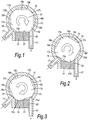
- the known pump of WO 2006/027548 is formed by a housing indicated generally at 10 which may be formed by a plastics moulding of, for example, polyethylene or polypropylene.
- the housing 10 is formed with an inlet 11 for connection to a source of fluid and an outlet 12 for pumped fluid.
- the interior of the housing 10 is cylindrical.
- the portion of the interior of the housing 10 between the outlet 12 and the inlet 11, again in clockwise direction as viewed in Figures 1 to 3 carries a seal 14 that will be described in more detail below.
- the housing 10 contains a rotor 15.
- the rotor 15 may be formed of stainless steel or as a precision injection moulded plastics part formed from a resin such as acetal.
- the rotor 15 is generally of circular cross-section and includes four recessed surfaces 16a, 16b, 16c and 16d of equal length equiangularly spaced around the rotor and interconnected by apices 17a, 17b, 17c and 17d formed by unrelieved portions of the rotor 15. Accordingly, each apex is rounded with a curvature that matches the curvature of the cylindrical housing surface 13 so that the rotor 15 is an interference fit within the cylindrical housing surface 13.
- each recessed surface 16a, 16b, 16c and 16d forms a respective chamber 18a, 18b, 18c and 18d with the cylindrical housing surface 13 as each surface 16a, 16b, 16c, 16d travels around that housing surface 13.
- the rotor 15 may be arranged to distend slightly the housing 10, so ensuring a fluid-tight seal around each surface 16a, 16b. 16c. 16d.
- the rotor 15 is rotated in a clockwise direction in Figures 1 to 3 by a drive (not shown in the Figures).
- the seal 14 is formed by a block of elastomeric material that is compliant, flexible and resilient such as that sold under the trade mark Hytrel.
- the seal 14 is connected to the housing 10 to prevent fluid passing between the seal 14 and the housing 10. This may be by use of an adhesive.
- the seal 14 could be moulded with the housing 10 in a 2-shot injection moulding process. In this latter case, the material of the seal 14 must be such that it welds to the housing to prevent leakage.
- the seal 14 has a first axial edge 19 adjacent the inlet 11 and a second axial edge 20 adjacent the outlet 12.
- the seal 14 has a rotor engaging surface 21 that has a length between the first and second edges 19, 20 that is generally equal to the length of each of the recessed surfaces 16a, 16b, 16c and 16d between the associated apices 17a, 17b, 17c, 17d and is shaped to match the shape of each recessed surface 16a, 16b, 16c, 16d.
- the axial extent of the seal 14 is that at least the same as the axial extent of the recessed surfaces 16a, 16b, 16c, 16d.
- the seal 14 projects into the space defined by an imaginary cylinder described by a continuation of the cylindrical surface 13 between the inlet 11 and the outlet 12.
- the seal 14 may be flexed between the first and second axial edges 19, 20 so that it bows outwardly relatively to the seal 14 towards the axis of the rotor 15 where the recessed surfaces 16a, 16b, 16c, 16d are concave.
- the inlet 11 is connected to a source of fluid to be pumped and the outlet 12 is connected to a destination for the pumped fluid.
- the rotor 15 is rotated in a clockwise direction as viewed in Figures 1 to 3 .
- the rotor surface 16a engages resiliently the seal surface 21. In this way, the space between the housing 10 and the rotor 15 is closed in this zone and the passage of fluid from the outlet 12 to the inlet 11 is prevented.
- the rotor 15 then moves to a position equivalent to the position shown in Figure 1 and pumping continues. In this way, fluid is pumped between the inlet 11 and the outlet 12.
- the rate of flow of liquid is proportional to the rate of rotation of the rotor 15 and the volumes of the chambers 18a, 18b, 18c and 18d.
- the rotor 15 is shown as having four surfaces 16a, 16b, 16c, 16d, it could have any number of surfaces such as one or two or three surfaces or more than four surfaces.
- the surfaces 16a, 16b, 16c, 16d may be planar, or may be, for example, convexly or concavely curved. They may be shaped as indentations formed by the intersection with the rotor 15 of an imaginary cylinder having its axis at 90° to the axis of the rotor and offset to one side of the rotor axis.
- the rotor engaging surface 21 of the seal 14 may be shaped to compliment the shape of the surfaces 16a, 16b, 16c, 16d.
- the seal 14 acts to prevent the formation of a chamber between the outlet 12 and the inlet 11 in the direction of the rotor 15.
- the resilience of the seal 14 allows it always to fill the space between the inlet 11 and the outlet 12 and the portion of the rotor 15 in this region.
- the use of a spring acting on the seal 14, as described above, will decrease that tendency and so allow the pump to operate at higher pressures.
- the force applied by the spring determines the maximum pump pressure. Pumps are known in which the outlet and the inlet are separated by a thin vane extending from the housing and contacting the rotor.
- a seal 114 is formed in one-piece with the housing 10. These parts may be formed from a plastics material by a single injection moulding process.
- the seal 114 is a thin plastics wall that extends circumferentially from the inlet 11 to the outlet 12.
- the thickness of the wall may, for example, be 0.15mm.
- the material of the housing 10 and the thickness of the wall are chosen such that the wall can distort when contacted by the apices 17a, 17b, 17c, 17d of the rotor 15. Suitable materials may be polyethylene or polypropylene.
- seal 114 In order for the seal 114 to be flexible enough to follow the contour of the rotor 15 as it rotates requires that the seal 114 be moulded with a very thin wall section. This requirement for a thin wall section over a large area is not normally encountered in typical injection moulded parts. By careful processing using high injection pressures, locally hot tooling around the seal area and local venting to eliminate gassing it is possible to achieve seals 114 with a wall thickness between 0.1mm - 0.3mm.
- the sliding portion of the tool that creates the outer surface of the seal 114 is controlled hydraulically.
- the molten plastic is injected into the tool by the injection screw in the conventional manner where the seal wall thickness is approximately twice the design thickness thus allowing the molten material to flow readily across the seal.
- the injection screw instead of using the injection screw to provide the packing pressure whilst the moulding cools and solidifies the sliding portion of the tool is advanced hydraulically to create the desired seal wall thickness and creating the packing pressure at the same time.
- seal 114 may require the moulding of stiffening members such as flanges on the housing 10 to provide it with sufficient rigidity.
- the presence of the unitarily formed seal 114 ensures that there is no leakage between adjacent chambers 18a, 18b, 18c and 18d at the joint between the housing 10 and the seal 114 as an apex 17a, 17b, 17c, 17d passes the joint, as may occur in the known embodiment of Figures 1 to 3 particularly at higher pressures. This gives a longer operational life.
- the use of a single shot moulding compared with twin shot or co-moulding processes reduces the number of processes, has a faster cycle time, requires simpler mould tools and mould machinery and leads to higher manufacturing yield and lower costs.
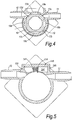
- the seal 114 is formed in one piece with the housing 10, as in Figure 4 . In this embodiment, however, there is provided a resilient displacer pad 141 that bears against the underside of the seal 114 to urge the seal against the rotor 15.
- the force applied by the pad 141 is chosen to allow the pump to operate at a lower end of a range of operating pressures for which the pump is designed, for example up to 0.5bar.
- a port 101 is provided in the outlet 12 to allow communication between the outlet 12 and the space behind the seal 114.
- the effect of this is to allow fluid to flow through the port 101 in operation and apply fluid pressure to a chamber 147 formed by the under surface of the seal 114, a turret 145 projecting outwardly from the rest of the housing 10 and a cap 146 closing the turret 145.
- the force applied by the seal 114 to the rotor is thus the sum of the force applied by the pad 141 and the force applied by the fluid. In this way, the applied force varies with the outlet pressure and an increase in outlet pressure results in a corresponding increase in the force applied to the seal 114 so preventing leakage between the seal 114 and the rotor 15 as a result of the increased pressure.
- pumps that have a maximum operating pressure of 1bar without the port 101 can be operated at pressures of up to and exceeding 6bar with the port 101.
- a single design of pump may be used for application requiring a variety of single pressures. It is not necessary to design the pump with a single limited range of operating pressures in mind.
- the pump always operates with the minimum torque requirement since the force between the seal 114 and the rotor 15 is never unnecessarily high.
- the fluid could be provided to the under surface from the inlet 11 or from any other suitable point within the housing 10 or supplied via a tube from a remote location in the fluid system, thus enabling the manufacture of a pump with high input pressure or output pressure.
- the interior of the housing 10 and the exterior of the rotor 15 have complementary cylindrical surfaces.
- the operating torque and the maximum pumping pressure are affected by the closeness of the fit between these parts and small manufacturing variations can have an adverse effect by increasing the required torque and by reducing the maximum pumping pressure through leakage.
Landscapes
- Engineering & Computer Science (AREA)
- Mechanical Engineering (AREA)
- General Engineering & Computer Science (AREA)
- Details And Applications Of Rotary Liquid Pumps (AREA)
- Rotary Pumps (AREA)
Claims (11)
- Pumpe, umfassend
ein Gehäuse (10), wobei das Gehäuse (10) Folgendes hat:eine Innenfläche, die eine Rotorbahn definiert,einen Einlass (11), der in dem Gehäuse (10) an einer ersten Position auf der Rotorbahn ausgebildet ist,einen Auslass (12), der in dem Gehäuse (10) an einer von der ersten Position beabstandeten zweiten Position auf der Rotorbahn ausgebildet ist,einen in dem Gehäuse drehbaren Rotor (15),wobei mindestens eine erste Fläche an dem Rotor (15) ausgebildet ist und gegen die Rotorbahn des Gehäuses (10) abdichtet,wobei mindestens eine zweite Fläche, die eine ausgesparte Fläche ist, an dem Rotor (15) ausgebildet ist, von der ersten Fläche umfangsmäßig beabstandet ist und eine Kammer mit der Rotorbahn bildet, die bei Drehung des Rotors (15) um die Rotorbahn fährt, um Fluid um das Gehäuse (10) von dem Einlass (11) zu dem Auslass (12) zu fördern,gekennzeichnet durcheine federnde Dichtung (14, 114), die in einem einteiligen Teil mit dem Gehäuse (10) ausgebildet ist, auf der Rotorbahn angeordnet ist und sich so zwischen dem Auslass (12) und dem Einlass (11) in der Rotationsrichtung des Rotors (15) erstreckt, dass die erste Rotorfläche mit der Dichtung (14, 114) abdichtet und sich federnd deformiert, wenn sich der Rotor (15) um die Rotorbahn in dem Gehäuse dreht, um zu verhindern, dass Fluid von dem Auslass (12) zu dem Einlass (11) an der Dichtung vorbei strömt. - Pumpe nach Anspruch 1, wobei das Gehäuse (10) und die Dichtung (14, 114) mittels eines einzigen Spritzgussprozesses aus einem Kunststoffmaterial gebildet sind.
- Pumpe nach Anspruch 1 oder Anspruch 2, wobei die Dichtung (14, 114) durch eine flexible Kunststoffwand gebildet ist.
- Pumpe nach einem der Ansprüche 2 bis 3, wobei die Wand eine Dicke von 0,1 mm bis 0,3 mm, vorzugsweise von 0,15 mm, hat.
- Pumpe nach einem der vorhergehenden Ansprüche, umfassend einen Durchgang (101) zum Zuführen eines Fluids zu einer Unterfläche, um die Dichtung (114) gegen den Rotor (15) zu drücken.
- Pumpe nach Anspruch 5, wobei das zu der Unterfläche zugeführte Fluid das gepumpte Fluid ist.
- Pumpe nach Anspruch 6, wobei das Gehäuse (10) mit einem Durchgang (101) versehen ist, der sich von dem Auslass (12) zu der Unterfläche erstreckt, um Fluid von dem Auslass (12) zu der Unterfläche zu führen.
- Pumpe nach einem der Ansprüche 5 bis 7, wobei das Gehäuse (10) mit einer Kammer gebildet ist, wobei die Dichtung (114) eine Wand der Kammer bildet, wobei das Fluid der Kammer zugeführt wird.
- Pumpe nach Anspruch 8, wenn von Anspruch 7 abhängig, wobei sich der Durchgang (101) von dem Auslass (12) zu der Kammer erstreckt.
- Pumpe nach Anspruch 6, wobei das Gehäuse (10) mit einem Durchgang versehen ist, der sich von dem Einlass (11) zu der Unterfläche erstreckt, um Fluid von dem Einlass (11) zu der Unterfläche zu führen.
- Pumpe nach einem der Ansprüche 5 bis 10, wobei ein federndes Glied (141) vorgesehen ist, das die Unterfläche der Dichtung (114) beaufschlagt.
Applications Claiming Priority (2)
| Application Number | Priority Date | Filing Date | Title |
|---|---|---|---|
| GBGB0906768.7A GB0906768D0 (en) | 2009-04-21 | 2009-04-21 | Pumps |
| PCT/GB2010/000798 WO2010122299A2 (en) | 2009-04-21 | 2010-04-21 | Pumps |
Publications (2)
| Publication Number | Publication Date |
|---|---|
| EP2422048A2 EP2422048A2 (de) | 2012-02-29 |
| EP2422048B1 true EP2422048B1 (de) | 2020-12-16 |
Family
ID=40774669
Family Applications (1)
| Application Number | Title | Priority Date | Filing Date |
|---|---|---|---|
| EP10719766.7A Active EP2422048B1 (de) | 2009-04-21 | 2010-04-21 | Pumpe mit elastischer dichtung |
Country Status (13)
| Country | Link |
|---|---|
| US (2) | US9175681B2 (de) |
| EP (1) | EP2422048B1 (de) |
| JP (1) | JP5670431B2 (de) |
| CN (1) | CN102449265B (de) |
| AU (2) | AU2010240676B2 (de) |
| BR (1) | BRPI1006572B1 (de) |
| CA (1) | CA2759433C (de) |
| ES (1) | ES2861423T3 (de) |
| GB (1) | GB0906768D0 (de) |
| IL (1) | IL215820A (de) |
| MX (1) | MX337264B (de) |
| PT (1) | PT2422048T (de) |
| WO (1) | WO2010122299A2 (de) |
Families Citing this family (29)
| Publication number | Priority date | Publication date | Assignee | Title |
|---|---|---|---|---|
| US9850118B2 (en) * | 2010-08-20 | 2017-12-26 | Pepsico, Inc. | Bag-in-box pump system |
| US9399312B2 (en) | 2011-03-14 | 2016-07-26 | Standex International Corporation | Plastic pump housing and manufacture thereof |
| US20130062811A1 (en) * | 2011-03-14 | 2013-03-14 | Standex International Corporation | Plastic pump housing and manufacture thereof |
| GB201117300D0 (en) * | 2011-10-07 | 2011-11-16 | Quantex Patents Ltd | Pumps |
| GB201117297D0 (en) * | 2011-10-07 | 2011-11-16 | Quantex Patents Ltd | Pump fittings and methods for their manufacture |
| RU2014128985A (ru) * | 2011-12-19 | 2016-02-10 | Экспоненшиал Текнолоджиз, Инк. | Расширитель объемного типа |
| GB201202255D0 (en) * | 2012-02-09 | 2012-03-28 | Quantex Patents Ltd | Pumps |
| US8622246B2 (en) | 2012-02-13 | 2014-01-07 | Ecolab Usa Inc. | Fluid reservoir docking station |
| GB2507029B (en) * | 2012-07-11 | 2019-04-17 | Quantex Patents Ltd | Pump fittings and methods for their manufacture |
| GB201218428D0 (en) * | 2012-10-15 | 2012-11-28 | Quantex Patents Ltd | Pump assemblies |
| EP2931412A2 (de) | 2012-12-13 | 2015-10-21 | 3M Innovative Properties Company | Abdeckungsanordnung für die abgabe von flüssigkeiten aus behältern |
| GB201303903D0 (en) * | 2013-03-05 | 2013-04-17 | Quantex Patents Ltd | Pumps |
| WO2015042361A1 (en) * | 2013-09-20 | 2015-03-26 | Standex International Corporation | Plastic pump housing and manufacture thereof |
| GB2528509A (en) * | 2014-07-24 | 2016-01-27 | Lontra Ltd | Rotary Piston and Cylinder Devices |
| GB201504553D0 (en) | 2015-03-18 | 2015-05-06 | Quantex Patents Ltd | Pumps |
| US20160281715A1 (en) * | 2015-03-27 | 2016-09-29 | Charles H. Tuckey | Vane Pump Assembly |
| EP3115610B1 (de) * | 2015-07-06 | 2021-04-14 | Goodrich Actuation Systems Limited | Hydraulikpumpe |
| GB2547051A (en) * | 2016-02-08 | 2017-08-09 | Quantex Patents Ltd | Pump assembly |
| IT201700031729A1 (it) * | 2017-03-22 | 2018-09-22 | Ali Group Srl Carpigiani | Pompa per l'erogazione di prodotti alimentari liquidi o semiliquidi o semisolidi e macchina comprendente detta pompa. |
| WO2019020063A1 (zh) * | 2017-07-26 | 2019-01-31 | 施育秧 | 一种液体泵出装置 |
| WO2019113704A1 (en) | 2017-12-13 | 2019-06-20 | Exponential Technologies, Inc. | Rotary fluid flow device |
| WO2020006105A1 (en) | 2018-06-29 | 2020-01-02 | Ecolab Usa Inc. | Chemical product dispensing using a fluid drive and return home interface |
| GB2576779A (en) | 2018-09-03 | 2020-03-04 | Quantex Patents Ltd | Dispenser systems, in-line dispenser assemblies, methods of using and cleaning same |
| DE102018133680A1 (de) * | 2018-12-28 | 2020-07-02 | Schwäbische Hüttenwerke Automotive GmbH | Rotationspumpe mit axialer Kompensation, Auslassdichtung für eine Pumpe sowie vormontierte Pumpeneinheit |
| US11168683B2 (en) | 2019-03-14 | 2021-11-09 | Exponential Technologies, Inc. | Pressure balancing system for a fluid pump |
| US11339045B2 (en) | 2020-10-20 | 2022-05-24 | Elkay Manufacturing Company | Flavor and additive delivery systems and methods for beverage dispensers |
| US20220145880A1 (en) | 2020-11-11 | 2022-05-12 | Server Products, Inc. | Flexible impeller pump for flowable food product |
| GB2606542B (en) | 2021-05-12 | 2023-10-11 | Psg Germany Gmbh | Pumps |
| GB2606544B (en) | 2021-05-12 | 2023-07-12 | Psg Germany Gmbh | Pumps |
Citations (1)
| Publication number | Priority date | Publication date | Assignee | Title |
|---|---|---|---|---|
| WO2006027548A1 (en) * | 2004-09-07 | 2006-03-16 | Pdd Innovations Limited | Rotary pump with resiliently deformed seal |
Family Cites Families (28)
| Publication number | Priority date | Publication date | Assignee | Title |
|---|---|---|---|---|
| US513315A (en) * | 1894-01-23 | Charles edwin funk | ||
| GB1182094A (en) * | 1968-01-30 | 1970-02-25 | Kovopodnik Mestsky Prumyslovy | Single-Spindle Pumps |
| US3507585A (en) * | 1968-04-24 | 1970-04-21 | William M Mercer | Rotary diaphragm pump |
| US3652192A (en) * | 1969-01-16 | 1972-03-28 | Lederle Pumpen & Maschf | Sealed conveying apparatus |
| JPS4924486B1 (de) * | 1969-06-12 | 1974-06-24 | ||
| DE2139949A1 (de) * | 1970-08-31 | 1972-03-02 | Environment/One Corp., Schenectady, N.Y. (V.St.A.) | Schraubenpumpe |
| SE351011B (de) * | 1971-03-16 | 1972-11-13 | Alfa Laval Ab | |
| JPS5256127Y2 (de) | 1972-06-05 | 1977-12-19 | ||
| JPS4924486A (de) | 1972-06-30 | 1974-03-04 | ||
| US3887307A (en) * | 1974-04-30 | 1975-06-03 | Curtiss Wright Corp | Rotary mechanism with die-cast trochoidal housing |
| US4028021A (en) * | 1975-12-08 | 1977-06-07 | Curtiss-Wright Corporation | Rotary trochoidal compressor with compressible sealing |
| DE2632716A1 (de) | 1976-07-21 | 1978-01-26 | Martin Theodor Melchior | Fluessigkeitspumpe, insbesondere fuer gips-anwurfgeraete |
| JPS54139103A (en) * | 1978-04-20 | 1979-10-29 | Tadaaki Kobayashi | Pumping plant provided with flexible stator |
| JPS60240890A (ja) * | 1984-05-14 | 1985-11-29 | Mitsubishi Heavy Ind Ltd | コンクリ−ト圧送用ポンプ |
| US4836759A (en) * | 1985-11-08 | 1989-06-06 | Nautical Services Pty. Ltd. | Rotary pump with orbiting rotor of harder material than stator |
| DE3815252A1 (de) * | 1988-05-05 | 1989-11-16 | Knf Neuberger Gmbh | Ringmembranpumpe |
| US5019311A (en) * | 1989-02-23 | 1991-05-28 | Koslow Technologies Corporation | Process for the production of materials characterized by a continuous web matrix or force point bonding |
| JP3208803B2 (ja) * | 1991-05-20 | 2001-09-17 | ソニー株式会社 | 物品の射出成形法、射出成形装置及びそれに用いる成形型体並びに磁気テープ用カセットハーフ |
| US5465748A (en) * | 1994-05-24 | 1995-11-14 | Millipore Corporation | Sanitizable slider diaphragm valve |
| JPH0924486A (ja) | 1995-07-13 | 1997-01-28 | Toshiba Corp | 低融点合金及びその粉末を用いたクリームはんだ |
| US5660536A (en) * | 1996-01-05 | 1997-08-26 | Brunswick Corporation | High capacity simplified sea water pump |
| CN2255512Y (zh) * | 1996-09-02 | 1997-06-04 | 陈艳根 | 柔性转子泵 |
| JP4033048B2 (ja) * | 2003-06-11 | 2008-01-16 | ソニー株式会社 | スピーカ振動板の製造方法及びスピーカ振動板 |
| KR20050066322A (ko) * | 2003-12-26 | 2005-06-30 | 삼성전자주식회사 | 압축기 |
| US7512592B2 (en) * | 2004-07-02 | 2009-03-31 | Tarari, Inc. | System and method of XML query processing |
| EP1877666A1 (de) * | 2005-05-06 | 2008-01-16 | Inter-Ice Pump APS | Rotor, herstellungsverfahren für einen solchen rotor und pumpe mit einem solchen rotor |
| DE502006002188D1 (de) * | 2006-01-26 | 2009-01-08 | Grundfos Management As | Exzenterschneckenpumpe |
| WO2008003279A2 (de) * | 2006-07-01 | 2008-01-10 | Ixetic Hückeswagen Gmbh | Vakuumpumpe, spritzgiesswerkzeug für das pumpengehäuse, herstellungsverfahren des pumpengehauses und herstellungsverfahren eines pumpengehäuses mit zwei in einem arbeitsgang hergestellten dichtungen |
-
2009
- 2009-04-21 GB GBGB0906768.7A patent/GB0906768D0/en not_active Ceased
-
2010
- 2010-04-21 BR BRPI1006572-5A patent/BRPI1006572B1/pt active IP Right Grant
- 2010-04-21 WO PCT/GB2010/000798 patent/WO2010122299A2/en active Application Filing
- 2010-04-21 CN CN201080022789.0A patent/CN102449265B/zh active Active
- 2010-04-21 EP EP10719766.7A patent/EP2422048B1/de active Active
- 2010-04-21 US US13/265,510 patent/US9175681B2/en active Active
- 2010-04-21 AU AU2010240676A patent/AU2010240676B2/en not_active Ceased
- 2010-04-21 JP JP2012506563A patent/JP5670431B2/ja active Active
- 2010-04-21 CA CA2759433A patent/CA2759433C/en active Active
- 2010-04-21 PT PT107197667T patent/PT2422048T/pt unknown
- 2010-04-21 ES ES10719766T patent/ES2861423T3/es active Active
- 2010-04-21 MX MX2011011098A patent/MX337264B/es active IP Right Grant
-
2011
- 2011-10-23 IL IL215820A patent/IL215820A/en active IP Right Grant
-
2015
- 2015-09-22 US US14/861,492 patent/US10465681B2/en active Active
-
2016
- 2016-04-05 AU AU2016202108A patent/AU2016202108B2/en active Active
Patent Citations (1)
| Publication number | Priority date | Publication date | Assignee | Title |
|---|---|---|---|---|
| WO2006027548A1 (en) * | 2004-09-07 | 2006-03-16 | Pdd Innovations Limited | Rotary pump with resiliently deformed seal |
Also Published As
| Publication number | Publication date |
|---|---|
| BRPI1006572A2 (pt) | 2018-05-22 |
| AU2016202108A1 (en) | 2016-04-28 |
| CN102449265B (zh) | 2014-06-18 |
| WO2010122299A8 (en) | 2011-11-17 |
| WO2010122299A3 (en) | 2011-04-28 |
| CA2759433C (en) | 2017-07-11 |
| CN102449265A (zh) | 2012-05-09 |
| PT2422048T (pt) | 2021-03-17 |
| MX337264B (es) | 2016-02-19 |
| JP2012524864A (ja) | 2012-10-18 |
| IL215820A0 (en) | 2012-01-31 |
| US20160010644A1 (en) | 2016-01-14 |
| EP2422048A2 (de) | 2012-02-29 |
| BRPI1006572B1 (pt) | 2021-02-02 |
| WO2010122299A2 (en) | 2010-10-28 |
| AU2010240676A1 (en) | 2011-11-10 |
| IL215820A (en) | 2014-11-30 |
| AU2010240676B2 (en) | 2016-03-03 |
| US10465681B2 (en) | 2019-11-05 |
| US9175681B2 (en) | 2015-11-03 |
| ES2861423T3 (es) | 2021-10-06 |
| CA2759433A1 (en) | 2010-10-28 |
| JP5670431B2 (ja) | 2015-02-18 |
| MX2011011098A (es) | 2012-04-30 |
| GB0906768D0 (en) | 2009-06-03 |
| US20120034122A1 (en) | 2012-02-09 |
| AU2016202108B2 (en) | 2016-11-03 |
Similar Documents
| Publication | Publication Date | Title |
|---|---|---|
| EP2422048B1 (de) | Pumpe mit elastischer dichtung | |
| EP1787027B1 (de) | Rotationspumpe mit elastisch verformter dichtung | |
| US7862311B2 (en) | Variable displacement vane pump | |
| US7014417B2 (en) | Auto suction hybrid pump | |
| US9765778B2 (en) | Variable displacement rotary pump and displacement regulation method | |
| EP2946113B1 (de) | Verstellpumpe mit mehreren druckkammern | |
| US20070041859A1 (en) | Rotary fluid-driven motor with sealing elements | |
| EP2828526B1 (de) | Verstellpumpe mit doppeltem exzenterring und verstellregelungsverfahren | |
| CN106884791B (zh) | 叶片泵装置 | |
| CN101270747A (zh) | 可变排量叶片泵 | |
| US5496159A (en) | Rotary displacement pump having a separable member that controls the fluid flowpath | |
| KR102654552B1 (ko) | 회전 용적형 펌프 | |
| JP2007297932A (ja) | 可変容量型ポンプ |
Legal Events
| Date | Code | Title | Description |
|---|---|---|---|
| PUAI | Public reference made under article 153(3) epc to a published international application that has entered the european phase |
Free format text: ORIGINAL CODE: 0009012 |
|
| 17P | Request for examination filed |
Effective date: 20111115 |
|
| AK | Designated contracting states |
Kind code of ref document: A2 Designated state(s): AT BE BG CH CY CZ DE DK EE ES FI FR GB GR HR HU IE IS IT LI LT LU LV MC MK MT NL NO PL PT RO SE SI SK SM TR |
|
| RAP1 | Party data changed (applicant data changed or rights of an application transferred) |
Owner name: QUANTEX PATENTS LIMITED |
|
| DAX | Request for extension of the european patent (deleted) | ||
| STAA | Information on the status of an ep patent application or granted ep patent |
Free format text: STATUS: EXAMINATION IS IN PROGRESS |
|
| 17Q | First examination report despatched |
Effective date: 20170412 |
|
| REG | Reference to a national code |
Ref country code: DE Ref legal event code: R079 Ref document number: 602010066150 Country of ref document: DE Free format text: PREVIOUS MAIN CLASS: F01C0005040000 Ipc: F04C0002220000 |
|
| RIC1 | Information provided on ipc code assigned before grant |
Ipc: F04C 2/22 20060101AFI20200515BHEP Ipc: F04C 15/00 20060101ALI20200515BHEP Ipc: F01C 5/04 20060101ALI20200515BHEP Ipc: F04C 5/00 20060101ALI20200515BHEP Ipc: F04C 15/06 20060101ALI20200515BHEP Ipc: F01C 19/00 20060101ALI20200515BHEP |
|
| GRAP | Despatch of communication of intention to grant a patent |
Free format text: ORIGINAL CODE: EPIDOSNIGR1 |
|
| STAA | Information on the status of an ep patent application or granted ep patent |
Free format text: STATUS: GRANT OF PATENT IS INTENDED |
|
| INTG | Intention to grant announced |
Effective date: 20200707 |
|
| GRAS | Grant fee paid |
Free format text: ORIGINAL CODE: EPIDOSNIGR3 |
|
| GRAA | (expected) grant |
Free format text: ORIGINAL CODE: 0009210 |
|
| STAA | Information on the status of an ep patent application or granted ep patent |
Free format text: STATUS: THE PATENT HAS BEEN GRANTED |
|
| AK | Designated contracting states |
Kind code of ref document: B1 Designated state(s): AT BE BG CH CY CZ DE DK EE ES FI FR GB GR HR HU IE IS IT LI LT LU LV MC MK MT NL NO PL PT RO SE SI SK SM TR |
|
| REG | Reference to a national code |
Ref country code: GB Ref legal event code: FG4D |
|
| REG | Reference to a national code |
Ref country code: IE Ref legal event code: FG4D |
|
| REG | Reference to a national code |
Ref country code: DE Ref legal event code: R096 Ref document number: 602010066150 Country of ref document: DE |
|
| REG | Reference to a national code |
Ref country code: AT Ref legal event code: REF Ref document number: 1345846 Country of ref document: AT Kind code of ref document: T Effective date: 20210115 |
|
| REG | Reference to a national code |
Ref country code: CH Ref legal event code: NV Representative=s name: NOVAGRAAF INTERNATIONAL SA, CH |
|
| REG | Reference to a national code |
Ref country code: PT Ref legal event code: SC4A Ref document number: 2422048 Country of ref document: PT Date of ref document: 20210317 Kind code of ref document: T Free format text: AVAILABILITY OF NATIONAL TRANSLATION Effective date: 20210311 |
|
| REG | Reference to a national code |
Ref country code: SE Ref legal event code: TRGR |
|
| REG | Reference to a national code |
Ref country code: NL Ref legal event code: FP |
|
| PG25 | Lapsed in a contracting state [announced via postgrant information from national office to epo] |
Ref country code: GR Free format text: LAPSE BECAUSE OF FAILURE TO SUBMIT A TRANSLATION OF THE DESCRIPTION OR TO PAY THE FEE WITHIN THE PRESCRIBED TIME-LIMIT Effective date: 20210317 Ref country code: NO Free format text: LAPSE BECAUSE OF FAILURE TO SUBMIT A TRANSLATION OF THE DESCRIPTION OR TO PAY THE FEE WITHIN THE PRESCRIBED TIME-LIMIT Effective date: 20210316 Ref country code: FI Free format text: LAPSE BECAUSE OF FAILURE TO SUBMIT A TRANSLATION OF THE DESCRIPTION OR TO PAY THE FEE WITHIN THE PRESCRIBED TIME-LIMIT Effective date: 20201216 |
|
| REG | Reference to a national code |
Ref country code: AT Ref legal event code: MK05 Ref document number: 1345846 Country of ref document: AT Kind code of ref document: T Effective date: 20201216 |
|
| PG25 | Lapsed in a contracting state [announced via postgrant information from national office to epo] |
Ref country code: LV Free format text: LAPSE BECAUSE OF FAILURE TO SUBMIT A TRANSLATION OF THE DESCRIPTION OR TO PAY THE FEE WITHIN THE PRESCRIBED TIME-LIMIT Effective date: 20201216 Ref country code: BG Free format text: LAPSE BECAUSE OF FAILURE TO SUBMIT A TRANSLATION OF THE DESCRIPTION OR TO PAY THE FEE WITHIN THE PRESCRIBED TIME-LIMIT Effective date: 20210316 |
|
| PG25 | Lapsed in a contracting state [announced via postgrant information from national office to epo] |
Ref country code: HR Free format text: LAPSE BECAUSE OF FAILURE TO SUBMIT A TRANSLATION OF THE DESCRIPTION OR TO PAY THE FEE WITHIN THE PRESCRIBED TIME-LIMIT Effective date: 20201216 |
|
| REG | Reference to a national code |
Ref country code: LT Ref legal event code: MG9D |
|
| PG25 | Lapsed in a contracting state [announced via postgrant information from national office to epo] |
Ref country code: LT Free format text: LAPSE BECAUSE OF FAILURE TO SUBMIT A TRANSLATION OF THE DESCRIPTION OR TO PAY THE FEE WITHIN THE PRESCRIBED TIME-LIMIT Effective date: 20201216 Ref country code: EE Free format text: LAPSE BECAUSE OF FAILURE TO SUBMIT A TRANSLATION OF THE DESCRIPTION OR TO PAY THE FEE WITHIN THE PRESCRIBED TIME-LIMIT Effective date: 20201216 Ref country code: CZ Free format text: LAPSE BECAUSE OF FAILURE TO SUBMIT A TRANSLATION OF THE DESCRIPTION OR TO PAY THE FEE WITHIN THE PRESCRIBED TIME-LIMIT Effective date: 20201216 Ref country code: SK Free format text: LAPSE BECAUSE OF FAILURE TO SUBMIT A TRANSLATION OF THE DESCRIPTION OR TO PAY THE FEE WITHIN THE PRESCRIBED TIME-LIMIT Effective date: 20201216 Ref country code: RO Free format text: LAPSE BECAUSE OF FAILURE TO SUBMIT A TRANSLATION OF THE DESCRIPTION OR TO PAY THE FEE WITHIN THE PRESCRIBED TIME-LIMIT Effective date: 20201216 Ref country code: SM Free format text: LAPSE BECAUSE OF FAILURE TO SUBMIT A TRANSLATION OF THE DESCRIPTION OR TO PAY THE FEE WITHIN THE PRESCRIBED TIME-LIMIT Effective date: 20201216 |
|
| PG25 | Lapsed in a contracting state [announced via postgrant information from national office to epo] |
Ref country code: AT Free format text: LAPSE BECAUSE OF FAILURE TO SUBMIT A TRANSLATION OF THE DESCRIPTION OR TO PAY THE FEE WITHIN THE PRESCRIBED TIME-LIMIT Effective date: 20201216 Ref country code: PL Free format text: LAPSE BECAUSE OF FAILURE TO SUBMIT A TRANSLATION OF THE DESCRIPTION OR TO PAY THE FEE WITHIN THE PRESCRIBED TIME-LIMIT Effective date: 20201216 |
|
| REG | Reference to a national code |
Ref country code: DE Ref legal event code: R097 Ref document number: 602010066150 Country of ref document: DE |
|
| PG25 | Lapsed in a contracting state [announced via postgrant information from national office to epo] |
Ref country code: IS Free format text: LAPSE BECAUSE OF FAILURE TO SUBMIT A TRANSLATION OF THE DESCRIPTION OR TO PAY THE FEE WITHIN THE PRESCRIBED TIME-LIMIT Effective date: 20210416 |
|
| REG | Reference to a national code |
Ref country code: ES Ref legal event code: FG2A Ref document number: 2861423 Country of ref document: ES Kind code of ref document: T3 Effective date: 20211006 |
|
| PLBE | No opposition filed within time limit |
Free format text: ORIGINAL CODE: 0009261 |
|
| STAA | Information on the status of an ep patent application or granted ep patent |
Free format text: STATUS: NO OPPOSITION FILED WITHIN TIME LIMIT |
|
| 26N | No opposition filed |
Effective date: 20210917 |
|
| PG25 | Lapsed in a contracting state [announced via postgrant information from national office to epo] |
Ref country code: MC Free format text: LAPSE BECAUSE OF FAILURE TO SUBMIT A TRANSLATION OF THE DESCRIPTION OR TO PAY THE FEE WITHIN THE PRESCRIBED TIME-LIMIT Effective date: 20201216 Ref country code: DK Free format text: LAPSE BECAUSE OF FAILURE TO SUBMIT A TRANSLATION OF THE DESCRIPTION OR TO PAY THE FEE WITHIN THE PRESCRIBED TIME-LIMIT Effective date: 20201216 |
|
| PG25 | Lapsed in a contracting state [announced via postgrant information from national office to epo] |
Ref country code: LU Free format text: LAPSE BECAUSE OF NON-PAYMENT OF DUE FEES Effective date: 20210421 |
|
| PG25 | Lapsed in a contracting state [announced via postgrant information from national office to epo] |
Ref country code: SI Free format text: LAPSE BECAUSE OF FAILURE TO SUBMIT A TRANSLATION OF THE DESCRIPTION OR TO PAY THE FEE WITHIN THE PRESCRIBED TIME-LIMIT Effective date: 20201216 |
|
| PG25 | Lapsed in a contracting state [announced via postgrant information from national office to epo] |
Ref country code: IS Free format text: LAPSE BECAUSE OF FAILURE TO SUBMIT A TRANSLATION OF THE DESCRIPTION OR TO PAY THE FEE WITHIN THE PRESCRIBED TIME-LIMIT Effective date: 20210416 |
|
| PGFP | Annual fee paid to national office [announced via postgrant information from national office to epo] |
Ref country code: NL Payment date: 20220426 Year of fee payment: 13 |
|
| PGFP | Annual fee paid to national office [announced via postgrant information from national office to epo] |
Ref country code: SE Payment date: 20220427 Year of fee payment: 13 Ref country code: PT Payment date: 20220509 Year of fee payment: 13 Ref country code: IE Payment date: 20220427 Year of fee payment: 13 |
|
| REG | Reference to a national code |
Ref country code: GB Ref legal event code: 732E Free format text: REGISTERED BETWEEN 20220714 AND 20220720 |
|
| PGFP | Annual fee paid to national office [announced via postgrant information from national office to epo] |
Ref country code: CH Payment date: 20220503 Year of fee payment: 13 Ref country code: BE Payment date: 20220427 Year of fee payment: 13 |
|
| PG25 | Lapsed in a contracting state [announced via postgrant information from national office to epo] |
Ref country code: HU Free format text: LAPSE BECAUSE OF FAILURE TO SUBMIT A TRANSLATION OF THE DESCRIPTION OR TO PAY THE FEE WITHIN THE PRESCRIBED TIME-LIMIT; INVALID AB INITIO Effective date: 20100421 Ref country code: CY Free format text: LAPSE BECAUSE OF FAILURE TO SUBMIT A TRANSLATION OF THE DESCRIPTION OR TO PAY THE FEE WITHIN THE PRESCRIBED TIME-LIMIT Effective date: 20201216 |
|
| REG | Reference to a national code |
Ref country code: GB Ref legal event code: 732E Free format text: REGISTERED BETWEEN 20230525 AND 20230601 |
|
| P01 | Opt-out of the competence of the unified patent court (upc) registered |
Effective date: 20230606 |
|
| REG | Reference to a national code |
Ref country code: SE Ref legal event code: EUG |
|
| REG | Reference to a national code |
Ref country code: CH Ref legal event code: PL |
|
| REG | Reference to a national code |
Ref country code: NL Ref legal event code: MM Effective date: 20230501 |
|
| REG | Reference to a national code |
Ref country code: BE Ref legal event code: MM Effective date: 20230430 |
|
| PGFP | Annual fee paid to national office [announced via postgrant information from national office to epo] |
Ref country code: GB Payment date: 20231003 Year of fee payment: 14 |
|
| PGFP | Annual fee paid to national office [announced via postgrant information from national office to epo] |
Ref country code: ES Payment date: 20231102 Year of fee payment: 14 |
|
| PG25 | Lapsed in a contracting state [announced via postgrant information from national office to epo] |
Ref country code: SE Free format text: LAPSE BECAUSE OF NON-PAYMENT OF DUE FEES Effective date: 20230422 Ref country code: PT Free format text: LAPSE BECAUSE OF NON-PAYMENT OF DUE FEES Effective date: 20231023 Ref country code: NL Free format text: LAPSE BECAUSE OF NON-PAYMENT OF DUE FEES Effective date: 20230501 Ref country code: LI Free format text: LAPSE BECAUSE OF NON-PAYMENT OF DUE FEES Effective date: 20230430 Ref country code: CH Free format text: LAPSE BECAUSE OF NON-PAYMENT OF DUE FEES Effective date: 20230430 |
|
| PGFP | Annual fee paid to national office [announced via postgrant information from national office to epo] |
Ref country code: TR Payment date: 20231003 Year of fee payment: 14 Ref country code: IT Payment date: 20231002 Year of fee payment: 14 Ref country code: FR Payment date: 20231005 Year of fee payment: 14 Ref country code: DE Payment date: 20231031 Year of fee payment: 14 |
|
| REG | Reference to a national code |
Ref country code: IE Ref legal event code: MM4A |
|
| PG25 | Lapsed in a contracting state [announced via postgrant information from national office to epo] |
Ref country code: BE Free format text: LAPSE BECAUSE OF NON-PAYMENT OF DUE FEES Effective date: 20230430 |
|
| PG25 | Lapsed in a contracting state [announced via postgrant information from national office to epo] |
Ref country code: IE Free format text: LAPSE BECAUSE OF NON-PAYMENT OF DUE FEES Effective date: 20230421 |
|
| PG25 | Lapsed in a contracting state [announced via postgrant information from national office to epo] |
Ref country code: MK Free format text: LAPSE BECAUSE OF FAILURE TO SUBMIT A TRANSLATION OF THE DESCRIPTION OR TO PAY THE FEE WITHIN THE PRESCRIBED TIME-LIMIT Effective date: 20201216 Ref country code: IE Free format text: LAPSE BECAUSE OF NON-PAYMENT OF DUE FEES Effective date: 20230421 |