US5496159A - Rotary displacement pump having a separable member that controls the fluid flowpath - Google Patents
Rotary displacement pump having a separable member that controls the fluid flowpath Download PDFInfo
- Publication number
- US5496159A US5496159A US08/216,214 US21621494A US5496159A US 5496159 A US5496159 A US 5496159A US 21621494 A US21621494 A US 21621494A US 5496159 A US5496159 A US 5496159A
- Authority
- US
- United States
- Prior art keywords
- pump
- inlet
- outlet
- fluid
- transitional
- Prior art date
- Legal status (The legal status is an assumption and is not a legal conclusion. Google has not performed a legal analysis and makes no representation as to the accuracy of the status listed.)
- Expired - Fee Related
Links
- 239000012530 fluid Substances 0.000 title claims abstract description 43
- 238000006073 displacement reaction Methods 0.000 title claims abstract description 17
- 230000007704 transition Effects 0.000 claims abstract 2
- 238000007789 sealing Methods 0.000 claims 1
- 238000001746 injection moulding Methods 0.000 description 11
- 238000004519 manufacturing process Methods 0.000 description 8
- 238000005086 pumping Methods 0.000 description 5
- 230000008859 change Effects 0.000 description 4
- 230000008901 benefit Effects 0.000 description 3
- 238000000034 method Methods 0.000 description 3
- 230000015572 biosynthetic process Effects 0.000 description 2
- 239000007788 liquid Substances 0.000 description 2
- 238000005058 metal casting Methods 0.000 description 2
- 230000004048 modification Effects 0.000 description 2
- 238000012986 modification Methods 0.000 description 2
- 238000009428 plumbing Methods 0.000 description 2
- 230000009471 action Effects 0.000 description 1
- 230000002411 adverse Effects 0.000 description 1
- 238000013459 approach Methods 0.000 description 1
- 230000002457 bidirectional effect Effects 0.000 description 1
- 238000005266 casting Methods 0.000 description 1
- 230000000694 effects Effects 0.000 description 1
- 230000003628 erosive effect Effects 0.000 description 1
- 238000009434 installation Methods 0.000 description 1
- 239000000463 material Substances 0.000 description 1
- 230000008569 process Effects 0.000 description 1
Images


Classifications
-
- F—MECHANICAL ENGINEERING; LIGHTING; HEATING; WEAPONS; BLASTING
- F01—MACHINES OR ENGINES IN GENERAL; ENGINE PLANTS IN GENERAL; STEAM ENGINES
- F01C—ROTARY-PISTON OR OSCILLATING-PISTON MACHINES OR ENGINES
- F01C21/00—Component parts, details or accessories not provided for in groups F01C1/00 - F01C20/00
- F01C21/10—Outer members for co-operation with rotary pistons; Casings
- F01C21/104—Stators; Members defining the outer boundaries of the working chamber
-
- F—MECHANICAL ENGINEERING; LIGHTING; HEATING; WEAPONS; BLASTING
- F04—POSITIVE - DISPLACEMENT MACHINES FOR LIQUIDS; PUMPS FOR LIQUIDS OR ELASTIC FLUIDS
- F04C—ROTARY-PISTON, OR OSCILLATING-PISTON, POSITIVE-DISPLACEMENT MACHINES FOR LIQUIDS; ROTARY-PISTON, OR OSCILLATING-PISTON, POSITIVE-DISPLACEMENT PUMPS
- F04C2/00—Rotary-piston machines or pumps
- F04C2/30—Rotary-piston machines or pumps having the characteristics covered by two or more groups F04C2/02, F04C2/08, F04C2/22, F04C2/24 or having the characteristics covered by one of these groups together with some other type of movement between co-operating members
- F04C2/34—Rotary-piston machines or pumps having the characteristics covered by two or more groups F04C2/02, F04C2/08, F04C2/22, F04C2/24 or having the characteristics covered by one of these groups together with some other type of movement between co-operating members having the movement defined in groups F04C2/08 or F04C2/22 and relative reciprocation between the co-operating members
- F04C2/344—Rotary-piston machines or pumps having the characteristics covered by two or more groups F04C2/02, F04C2/08, F04C2/22, F04C2/24 or having the characteristics covered by one of these groups together with some other type of movement between co-operating members having the movement defined in groups F04C2/08 or F04C2/22 and relative reciprocation between the co-operating members with vanes reciprocating with respect to the inner member
- F04C2/3441—Rotary-piston machines or pumps having the characteristics covered by two or more groups F04C2/02, F04C2/08, F04C2/22, F04C2/24 or having the characteristics covered by one of these groups together with some other type of movement between co-operating members having the movement defined in groups F04C2/08 or F04C2/22 and relative reciprocation between the co-operating members with vanes reciprocating with respect to the inner member the inner and outer member being in contact along one line or continuous surface substantially parallel to the axis of rotation
- F04C2/3442—Rotary-piston machines or pumps having the characteristics covered by two or more groups F04C2/02, F04C2/08, F04C2/22, F04C2/24 or having the characteristics covered by one of these groups together with some other type of movement between co-operating members having the movement defined in groups F04C2/08 or F04C2/22 and relative reciprocation between the co-operating members with vanes reciprocating with respect to the inner member the inner and outer member being in contact along one line or continuous surface substantially parallel to the axis of rotation the surfaces of the inner and outer member, forming the working space, being surfaces of revolution
-
- F—MECHANICAL ENGINEERING; LIGHTING; HEATING; WEAPONS; BLASTING
- F04—POSITIVE - DISPLACEMENT MACHINES FOR LIQUIDS; PUMPS FOR LIQUIDS OR ELASTIC FLUIDS
- F04C—ROTARY-PISTON, OR OSCILLATING-PISTON, POSITIVE-DISPLACEMENT MACHINES FOR LIQUIDS; ROTARY-PISTON, OR OSCILLATING-PISTON, POSITIVE-DISPLACEMENT PUMPS
- F04C2250/00—Geometry
- F04C2250/10—Geometry of the inlet or outlet
Definitions
- This invention relates to rotary displacement pumps, and more particularly, to a rotary displacement pump having a separable member that controls transitional regions and thereby the fluid flowpath.
- a rotary displacement pump can be loosely defined as one in which the main pumping action is caused by relative movement between rotating elements and stationary elements.
- One popular type of rotary pump is the vane and rotor pump. Although this type of pump shall be described herein, it should be noted that the present invention is applicable to other designs and is not limited to rigid vane rotary pumps.
- other applicable pumps can include an external gear pump, an internal gear pump, a screw and wheel pump, a multiple rotor screw pump, an external circumferential piston pump, an internal circumferential piston pump, various lobe pumps, a single screw pump, external vane-in-body pump, a flexible vane pump, a flexible liner pump, and a flexible tube pump.
- Transitional inlet and outlet regions into the fluid flowpath of a pump are critically important in almost all pump applications as described in the "Pump Handbook." These transitional regions are often recessed ports which change the internal geometry of the flowpath within the pump at the areas where fluid enters the flowpath and exits the flowpath. Properly designed transitional regions are important primarily for two reasons. First, without proper port design, unfavorable flow inlet and outlet conditions will develop resulting in inlet and outlet losses that lower the efficiency of the pump. Secondly, without properly transitional regions, there will be sharp corners in the flow path geometry causing rapid flow direction changes. This greatly increases the likelihood of cavitation especially at higher pump speeds or when the fluid medium is of low viscosity. Cavitation is vapor formation in the form of very tiny bubbles at any area in the flow path where the local pressure approaches or drops below the vapor pressure of the fluid medium.
- Cavitation adversely affects pump performance in three ways. Since this type of pump is a fixed displacement device, if, for example, only half of the actual fluid volume swept from the inlet chamber transitional region is vapor, then only half the normal capacity liquid volume is available at the outlet transitional region chamber, and the pump capacity is reduced accordingly. Secondly, physical damage to internal pump components and surfaces is caused by the collapse of cavitation vapor bubbles. This is known as cavitation erosion or pitting. Finally, cavitation often results in noisy and rough operation caused by the formation and collapse of vapor bubbles. All three have a negative effect on pump efficiency and/or component life.
- Another desirable attribute which can be used in designing a rotary displacement pump is that of a substantial colinear alignment of the inlet and outlet transitional regions and corresponding inlet and outlet fittings.
- Colinear alignment of the inlet and outlet fittings makes plumbing connections in many applications greatly simplified.
- a straight section of fluid plumbing, for instance, can be broken and the pump inserted directly in the line with no further modification.
- the straight through flow offer simple system connections, it also has additional system benefits. For instance, some systems rely on rapid and efficient drain back of fluid through the system, and specifically the pump. Any configuration other than the straight through flow configuration would trap significantly more fluid after drain back, therefore, the colinear inlet and outlet fitting configuration is very important to pump performance in many applications.
- transitional region design and system inlet and outlet transitional regions aligned substantially in a colinear manner are two features that are critical to pump performance, but can be difficult and costly to manufacture.
- straight through inlet and outlet fitting alignment is combined with the necessity for transitional regions provided by recessed inlet and outlet ports, severe tooling difficulties are encountered. These difficulties are the reason that pumps of this configuration are either made from processes such as metal casting, made without recessed port designs, or made with inlet and outlet fittings which are not colinear.
- FIGS. 1, 2a, and 2b each of these possibilities are generally inferior to the proposed invention.
- FIG. 1 shows the components and critical flow path elements of a standard rotary vane pump 10 of the prior art.
- Rotary pump 10 includes a body 11, transitional inlet region 12, transitional outlet region 14, rotor 16, vanes 18, inlet fitting 20 outlet fitting 22 and internal flow area 24.
- Rotor 16 is disposed in an eccentric relationship to the internal casing of body 11.
- transitional inlet region 12 and transitional outlet region 14 are recesses in the substantially circular interior of pump 10. As discussed above, the shapes of these transitional regions are critical to pump performance. Also note, that the flow direction at inlet fitting 20 is substantially the same as at the outlet fitting 22 making the pump colinear.
- Pump 10 of FIG. 1 can be adequate for some applications, however, it is inflexible in design and expensive to manufacture.
- the pump as shown requires a casting method to be manufacturable, and has the typical configuration of a body housing all the pumping components along with a separable cover (not shown).
- the transitional regions of this device are designed to a meet certain flowpath specifications which may be determined by the fluid it will be pumping or the velocity the fluid will be traveling through the pump.
- a redesign would be required to change the flow path specifications to meet requirements for a fluid with different characteristics or for a different fluid velocity.
- manufacturing this device using a metal casting method could be very expensive.
- FIGS. 2a and 2b show two popular examples of changing pump geometry to enable manufacturing by injection molding and therefore less expensive pump designs than that of FIG. 1.
- both pumps include a main body housing the pumping elements with a cover (not shown).
- Pump 26 of FIG. 2a has a colinear design which is desirable in many applications.
- pump 26 does not provide for varied design in either transitional inlet region 28 or transitional outlet region 30.
- the transitional regions of pump 26 are simply ports, with no specific design or shape to increase pump efficiency. Therefore, pump 26 is only a marginal design because the transitional regions cannot be shaped to enhance pump efficiency.
- Pump 34 of FIG. 2b is another example of a pump which can be manufactured using injection molding.
- Pump 34 of FIG. 2b has a limited ability to change the design of transitional inlet region 36 and transitional outlet region 38.
- the inlet and outlet fittings to the pump are not colinear making this pump inappropriate for certain applications.
- a rotary displacement pump including an external member having inlet and outlet channels and a cavity. Also included is an internal member having a shell with an inlet opening and an outlet opening therein, the shell being received in the cavity so that the inlet opening and the outlet opening is aligned with the inlet and outlet channels. Further included is a fluid drive member received within the shell for moving fluid from the inlet to outlet channels.
- FIG. 1 is a sectional view showing the basic components of a rigid vane rotary displacement pump of the prior art
- FIG. 2a is a sectional view depicting a colinear pump design of the prior art that is suitable for injection molding
- FIG. 2b is a sectional view a non-colinear pump design of the prior art that is suitable for injection molding;
- FIG. 3 is a sectional view depicting the pump of the present invention.
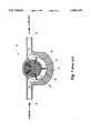
- FIG. 4 is a cross sectional view taken substantially across line 4--4 of the pump shown in FIG. 3;
- FIG. 5 is an exploded view of the pump of FIG. 3;
- FIG. 6 is an exploded view, taken in the opposite direction, of the pump of FIG. 3 further including a motor.
- the pumps of the prior art discussed thus far with reference to FIGS. 1 and 2 include a body that contains all of the necessary flowpath elements and a cover that seals the fluid flowpath within the body.
- the present invention provides a pump design which divides the necessary flowpath elements between two members, referred to herein as the internal housing and the external housing.
- the division of the flowpath elements provides a means for designing variable flowpaths by changing the designs of the transitional regions resident on the separable internal housing member. Therefore, the pump design of the present invention can be used for various fluids and flow conditions by changing only one element.
- FIG. 3 shows a cross section of assembled pump 50 in accordance with the present invention.
- Pump 50 has transitional inlet region 54 and transitional outlet region 56 corresponding to inlet fitting 58 and outlet fitting 60 respectively.
- Inlet fitting 58 has a channel and port for allowing fluid to pass though and into transitional inlet region 54.
- outlet fitting 60 has a channel and port for allowing fluid to pass from transitional outlet region 56 out through fitting 60.
- pump 50 Also included in pump 50 is rotor 62 and vanes 64 acting as a fluid drive member. As shown, fluid medium is moved by vanes 64 from transitional inlet region 54 through internal flow area 68 and out through transitional outlet region 56.
- the body of pump 50 is comprised of external housing 70 and internal housing 72, where internal housing 72 is a separable member which can be customized to control fluid flow though the design of transitional inlet region 54 and transitional outlet region 56.
- FIG. 4 includes motor 74 for driving rotor 62.
- Motor 74 has drive shaft 75 which is inserted into rotor 62 causing rotor 62 to rotate and thus, move fluid through pump 50.
- Shaft 75 of motor 74 is sealed within internal housing 72 by shaft seals 76.
- pump 50 has been described as a unidirectional pump, it can be appreciated that pump 50 could also be used as a bidirectional pump when the design of the transitional inlet region and the transitional outlet region are substantially the same.
- external housing 70 includes inlet fitting 58, outlet fitting 60 with corresponding port 80 and port 82.
- Internal housing 72 includes transitional inlet region 54 and transitional outlet region 56 made within shell 73 of internal housing 72.
- port 80 FIG. 4
- port 82 of external housing 70 is aligned with transitional outlet region 54 of internal housing 72. The alignment of ports and transitional regions allows the fluid medium to flow through the pump.
- rotor 62 with vanes 64 slideably mounted in place is disposed in an eccentric relationship into space 84 of shell 73.
- Shell 73 of internal housing 72 is then slid into cavity 86 of external housing 70 to complete the assembly.
- An interference seal between the wall of cavity 86 and the surface of shell 73, along with fastening devices such as screws, are used to hold internal housing 72 in place within external housing 70 to prevent fluid leaks.
- An o-ring (not shown) is also used in between internal housing 72 and external housing 70 to prevent leaks.
Landscapes
- Engineering & Computer Science (AREA)
- Mechanical Engineering (AREA)
- General Engineering & Computer Science (AREA)
- Rotary Pumps (AREA)
- Details And Applications Of Rotary Liquid Pumps (AREA)
Abstract
Description
Claims (4)
Priority Applications (1)
| Application Number | Priority Date | Filing Date | Title |
|---|---|---|---|
| US08/216,214 US5496159A (en) | 1994-03-22 | 1994-03-22 | Rotary displacement pump having a separable member that controls the fluid flowpath |
Applications Claiming Priority (1)
| Application Number | Priority Date | Filing Date | Title |
|---|---|---|---|
| US08/216,214 US5496159A (en) | 1994-03-22 | 1994-03-22 | Rotary displacement pump having a separable member that controls the fluid flowpath |
Publications (1)
| Publication Number | Publication Date |
|---|---|
| US5496159A true US5496159A (en) | 1996-03-05 |
Family
ID=22806209
Family Applications (1)
| Application Number | Title | Priority Date | Filing Date |
|---|---|---|---|
| US08/216,214 Expired - Fee Related US5496159A (en) | 1994-03-22 | 1994-03-22 | Rotary displacement pump having a separable member that controls the fluid flowpath |
Country Status (1)
| Country | Link |
|---|---|
| US (1) | US5496159A (en) |
Cited By (5)
| Publication number | Priority date | Publication date | Assignee | Title |
|---|---|---|---|---|
| US6106257A (en) * | 1998-07-10 | 2000-08-22 | Chen; Jen-Hsin | Hydraulic power transmission system |
| US6503064B1 (en) | 1999-07-15 | 2003-01-07 | Lucas Aerospace Power Transmission | Bi-directional low maintenance vane pump |
| US20140117667A1 (en) * | 2011-07-06 | 2014-05-01 | Voith Patent Gmbh | Marine current power plant and a method for its operation |
| CN107503937A (en) * | 2017-08-04 | 2017-12-22 | 余姚市锋哲电器厂 | Vehicular electric oil rig |
| US20180010612A1 (en) * | 2016-07-08 | 2018-01-11 | Fenwal, Inc. | Flexible Impeller Pumps And Disposable Fluid Flow Circuits Incorporating Such Pumps |
Citations (8)
| Publication number | Priority date | Publication date | Assignee | Title |
|---|---|---|---|---|
| US2738775A (en) * | 1952-03-10 | 1956-03-20 | Elmer D Smyser | Fluid meters |
| US3873231A (en) * | 1972-08-11 | 1975-03-25 | Allis Chalmers | Centrifugal pump diffuser |
| US4229147A (en) * | 1978-02-23 | 1980-10-21 | Robert Bosch Gmbh | Rotary positive-displacement pump |
| US4640125A (en) * | 1985-04-08 | 1987-02-03 | Lake Charles Instruments, Inc. | Rotary metering device useful with abrasive fluids |
| US4770616A (en) * | 1982-11-20 | 1988-09-13 | Itt Industries, Inc. | Variable vane-type pump |
| US5096390A (en) * | 1990-10-16 | 1992-03-17 | Micropump Corporation | Pump assembly with integral electronically commutated drive system |
| US5144802A (en) * | 1990-06-06 | 1992-09-08 | Ivan Ruzic | Rotary fluid apparatus having pairs of connected vanes |
| US5160252A (en) * | 1990-06-07 | 1992-11-03 | Edwards Thomas C | Rotary vane machines with anti-friction positive bi-axial vane motion controls |
-
1994
- 1994-03-22 US US08/216,214 patent/US5496159A/en not_active Expired - Fee Related
Patent Citations (8)
| Publication number | Priority date | Publication date | Assignee | Title |
|---|---|---|---|---|
| US2738775A (en) * | 1952-03-10 | 1956-03-20 | Elmer D Smyser | Fluid meters |
| US3873231A (en) * | 1972-08-11 | 1975-03-25 | Allis Chalmers | Centrifugal pump diffuser |
| US4229147A (en) * | 1978-02-23 | 1980-10-21 | Robert Bosch Gmbh | Rotary positive-displacement pump |
| US4770616A (en) * | 1982-11-20 | 1988-09-13 | Itt Industries, Inc. | Variable vane-type pump |
| US4640125A (en) * | 1985-04-08 | 1987-02-03 | Lake Charles Instruments, Inc. | Rotary metering device useful with abrasive fluids |
| US5144802A (en) * | 1990-06-06 | 1992-09-08 | Ivan Ruzic | Rotary fluid apparatus having pairs of connected vanes |
| US5160252A (en) * | 1990-06-07 | 1992-11-03 | Edwards Thomas C | Rotary vane machines with anti-friction positive bi-axial vane motion controls |
| US5096390A (en) * | 1990-10-16 | 1992-03-17 | Micropump Corporation | Pump assembly with integral electronically commutated drive system |
Non-Patent Citations (2)
| Title |
|---|
| Little, Jr., C. W. Rotary Pumps. In: Karassik, I. J., Krutzsch, W. C., Fraser, J. P. and Messina, J. P., Editors, Pump Handbook. New Jersey; McGraw Hill Book Company, pp. 3 70 through 3 99. * |
| Little, Jr., C. W. Rotary Pumps. In: Karassik, I. J., Krutzsch, W. C., Fraser, J. P. and Messina, J. P., Editors, Pump Handbook. New Jersey; McGraw-Hill Book Company, pp. 3-70 through 3-99. |
Cited By (7)
| Publication number | Priority date | Publication date | Assignee | Title |
|---|---|---|---|---|
| US6106257A (en) * | 1998-07-10 | 2000-08-22 | Chen; Jen-Hsin | Hydraulic power transmission system |
| US6503064B1 (en) | 1999-07-15 | 2003-01-07 | Lucas Aerospace Power Transmission | Bi-directional low maintenance vane pump |
| US20140117667A1 (en) * | 2011-07-06 | 2014-05-01 | Voith Patent Gmbh | Marine current power plant and a method for its operation |
| US20180010612A1 (en) * | 2016-07-08 | 2018-01-11 | Fenwal, Inc. | Flexible Impeller Pumps And Disposable Fluid Flow Circuits Incorporating Such Pumps |
| US10865805B2 (en) * | 2016-07-08 | 2020-12-15 | Fenwal, Inc. | Flexible impeller pumps and disposable fluid flow circuits incorporating such pumps |
| CN107503937A (en) * | 2017-08-04 | 2017-12-22 | 余姚市锋哲电器厂 | Vehicular electric oil rig |
| CN107503937B (en) * | 2017-08-04 | 2019-04-30 | 余姚市锋哲电器厂 | Vehicular electric oil rig |
Similar Documents
| Publication | Publication Date | Title |
|---|---|---|
| EP2422048B1 (en) | Pump with a resilient seal | |
| US4519755A (en) | Gerotor vacuum pump | |
| US7862311B2 (en) | Variable displacement vane pump | |
| US6030195A (en) | Rotary pump with hydraulic vane actuation | |
| US20210062655A1 (en) | Rotary Machine With Pressure Relief Mechanism | |
| US20070041859A1 (en) | Rotary fluid-driven motor with sealing elements | |
| US4390331A (en) | Positive displacement four lobe impeller structure | |
| US5076758A (en) | Centrifugal pumps | |
| US4747744A (en) | Magnetic drive gerotor pump | |
| MXPA01004909A (en) | Fluid energy transfer device. | |
| JP2002202072A (en) | Rotary fluid pressure vane pump for improving port structure of under vane | |
| US5354188A (en) | Sickleless internal gear pump with radially movable sealing elements for radial compensation | |
| EP2828526B1 (en) | Variable displacement pump with double eccentric ring and displacement regulation method | |
| CA2656886A1 (en) | Method of operation of a spherical positive displacement rotary machine and devices for carrying out said method | |
| US4836760A (en) | Inlet for a positive displacement pump | |
| US5496159A (en) | Rotary displacement pump having a separable member that controls the fluid flowpath | |
| TW202219387A (en) | Liquid blade pump | |
| JP2004513299A (en) | pump | |
| JPH01104991A (en) | Variable displacement gear pump | |
| US4774875A (en) | Actuator seal arrangement | |
| US20020051721A1 (en) | Vane pump | |
| US20080138198A1 (en) | Vane pump | |
| EP0389838B1 (en) | Housing for rotary pump | |
| US4716726A (en) | Adjustable rotary vane pump | |
| KR100381801B1 (en) | Rotary displacement pump |
Legal Events
| Date | Code | Title | Description |
|---|---|---|---|
| AS | Assignment |
Owner name: XEROX CORPORATION, CONNECTICUT Free format text: ASSIGNMENT OF ASSIGNORS INTEREST;ASSIGNOR:DEVORE, RONALD D.;REEL/FRAME:006940/0488 Effective date: 19940322 |
|
| FPAY | Fee payment |
Year of fee payment: 4 |
|
| AS | Assignment |
Owner name: BANK ONE, NA, AS ADMINISTRATIVE AGENT, ILLINOIS Free format text: SECURITY INTEREST;ASSIGNOR:XEROX CORPORATION;REEL/FRAME:013153/0001 Effective date: 20020621 |
|
| REMI | Maintenance fee reminder mailed | ||
| FPAY | Fee payment |
Year of fee payment: 8 |
|
| SULP | Surcharge for late payment |
Year of fee payment: 7 |
|
| AS | Assignment |
Owner name: JPMORGAN CHASE BANK, AS COLLATERAL AGENT, TEXAS Free format text: SECURITY AGREEMENT;ASSIGNOR:XEROX CORPORATION;REEL/FRAME:015134/0476 Effective date: 20030625 Owner name: JPMORGAN CHASE BANK, AS COLLATERAL AGENT,TEXAS Free format text: SECURITY AGREEMENT;ASSIGNOR:XEROX CORPORATION;REEL/FRAME:015134/0476 Effective date: 20030625 |
|
| REMI | Maintenance fee reminder mailed | ||
| LAPS | Lapse for failure to pay maintenance fees | ||
| STCH | Information on status: patent discontinuation |
Free format text: PATENT EXPIRED DUE TO NONPAYMENT OF MAINTENANCE FEES UNDER 37 CFR 1.362 |
|
| FP | Lapsed due to failure to pay maintenance fee |
Effective date: 20080305 |
|
| AS | Assignment |
Owner name: XEROX CORPORATION, CONNECTICUT Free format text: RELEASE BY SECURED PARTY;ASSIGNOR:JPMORGAN CHASE BANK, N.A. AS SUCCESSOR-IN-INTEREST ADMINISTRATIVE AGENT AND COLLATERAL AGENT TO JPMORGAN CHASE BANK;REEL/FRAME:066728/0193 Effective date: 20220822 |