EP2421690B1 - Heating system and method of heating a body of a preform - Google Patents
Heating system and method of heating a body of a preform Download PDFInfo
- Publication number
- EP2421690B1 EP2421690B1 EP10717806.3A EP10717806A EP2421690B1 EP 2421690 B1 EP2421690 B1 EP 2421690B1 EP 10717806 A EP10717806 A EP 10717806A EP 2421690 B1 EP2421690 B1 EP 2421690B1
- Authority
- EP
- European Patent Office
- Prior art keywords
- light
- light source
- preform
- heating system
- arrangement
- Prior art date
- Legal status (The legal status is an assumption and is not a legal conclusion. Google has not performed a legal analysis and makes no representation as to the accuracy of the status listed.)
- Active
Links
Images


Classifications
-
- B—PERFORMING OPERATIONS; TRANSPORTING
- B29—WORKING OF PLASTICS; WORKING OF SUBSTANCES IN A PLASTIC STATE IN GENERAL
- B29B—PREPARATION OR PRETREATMENT OF THE MATERIAL TO BE SHAPED; MAKING GRANULES OR PREFORMS; RECOVERY OF PLASTICS OR OTHER CONSTITUENTS OF WASTE MATERIAL CONTAINING PLASTICS
- B29B13/00—Conditioning or physical treatment of the material to be shaped
- B29B13/02—Conditioning or physical treatment of the material to be shaped by heating
- B29B13/023—Half-products, e.g. films, plates
- B29B13/024—Hollow bodies, e.g. tubes or profiles
- B29B13/025—Tube ends
-
- B—PERFORMING OPERATIONS; TRANSPORTING
- B29—WORKING OF PLASTICS; WORKING OF SUBSTANCES IN A PLASTIC STATE IN GENERAL
- B29C—SHAPING OR JOINING OF PLASTICS; SHAPING OF MATERIAL IN A PLASTIC STATE, NOT OTHERWISE PROVIDED FOR; AFTER-TREATMENT OF THE SHAPED PRODUCTS, e.g. REPAIRING
- B29C35/00—Heating, cooling or curing, e.g. crosslinking or vulcanising; Apparatus therefor
- B29C35/02—Heating or curing, e.g. crosslinking or vulcanizing during moulding, e.g. in a mould
- B29C35/08—Heating or curing, e.g. crosslinking or vulcanizing during moulding, e.g. in a mould by wave energy or particle radiation
- B29C35/0805—Heating or curing, e.g. crosslinking or vulcanizing during moulding, e.g. in a mould by wave energy or particle radiation using electromagnetic radiation
- B29C2035/0838—Heating or curing, e.g. crosslinking or vulcanizing during moulding, e.g. in a mould by wave energy or particle radiation using electromagnetic radiation using laser
-
- B—PERFORMING OPERATIONS; TRANSPORTING
- B29—WORKING OF PLASTICS; WORKING OF SUBSTANCES IN A PLASTIC STATE IN GENERAL
- B29C—SHAPING OR JOINING OF PLASTICS; SHAPING OF MATERIAL IN A PLASTIC STATE, NOT OTHERWISE PROVIDED FOR; AFTER-TREATMENT OF THE SHAPED PRODUCTS, e.g. REPAIRING
- B29C2949/00—Indexing scheme relating to blow-moulding
- B29C2949/07—Preforms or parisons characterised by their configuration
- B29C2949/0715—Preforms or parisons characterised by their configuration the preform having one end closed
-
- B—PERFORMING OPERATIONS; TRANSPORTING
- B29—WORKING OF PLASTICS; WORKING OF SUBSTANCES IN A PLASTIC STATE IN GENERAL
- B29C—SHAPING OR JOINING OF PLASTICS; SHAPING OF MATERIAL IN A PLASTIC STATE, NOT OTHERWISE PROVIDED FOR; AFTER-TREATMENT OF THE SHAPED PRODUCTS, e.g. REPAIRING
- B29C49/00—Blow-moulding, i.e. blowing a preform or parison to a desired shape within a mould; Apparatus therefor
- B29C49/02—Combined blow-moulding and manufacture of the preform or the parison
- B29C49/06—Injection blow-moulding
-
- B—PERFORMING OPERATIONS; TRANSPORTING
- B29—WORKING OF PLASTICS; WORKING OF SUBSTANCES IN A PLASTIC STATE IN GENERAL
- B29C—SHAPING OR JOINING OF PLASTICS; SHAPING OF MATERIAL IN A PLASTIC STATE, NOT OTHERWISE PROVIDED FOR; AFTER-TREATMENT OF THE SHAPED PRODUCTS, e.g. REPAIRING
- B29C49/00—Blow-moulding, i.e. blowing a preform or parison to a desired shape within a mould; Apparatus therefor
- B29C49/42—Component parts, details or accessories; Auxiliary operations
- B29C49/64—Heating or cooling preforms, parisons or blown articles
- B29C49/6409—Thermal conditioning of preforms
- B29C49/6418—Heating of preforms
-
- B—PERFORMING OPERATIONS; TRANSPORTING
- B29—WORKING OF PLASTICS; WORKING OF SUBSTANCES IN A PLASTIC STATE IN GENERAL
- B29C—SHAPING OR JOINING OF PLASTICS; SHAPING OF MATERIAL IN A PLASTIC STATE, NOT OTHERWISE PROVIDED FOR; AFTER-TREATMENT OF THE SHAPED PRODUCTS, e.g. REPAIRING
- B29C49/00—Blow-moulding, i.e. blowing a preform or parison to a desired shape within a mould; Apparatus therefor
- B29C49/42—Component parts, details or accessories; Auxiliary operations
- B29C49/64—Heating or cooling preforms, parisons or blown articles
- B29C49/6409—Thermal conditioning of preforms
- B29C49/6436—Thermal conditioning of preforms characterised by temperature differential
Definitions
- the invention concerns a heating system and a method of heating a body of a preform comprising a material thickness bounded by a first surface and a second surface.
- Preforms in particular plastic preforms, are widely used for producing a variety of products ranging from curved surfaces to beverage bottles, for instance.
- preforms are widely used for producing a variety of products ranging from curved surfaces to beverage bottles, for instance.
- they have to be heated up to a temperature close to the melting point of the material of the preform.
- Shaping tools will then alter the shape so that a completely new product evolves.
- Such shaping methods include deep-drawing or blow-moulding of plastic preforms.
- FIG. 1 shows a schematic sectional view of such a heating arrangement according to the state of the art.
- a body 1 of a preform having a first, outer, surface 2 and a second, inner surface 4 is heated by three halogen lamps 5.
- mirrors 7 are used to reflect parts of the divergent light 3 emitted by the halogen lamps 5 and to direct the light rays essentially into a traversal direction T of the preform 1.
- the traversal direction T is defined by a shortest direct line between the first surface 2 and the second surface 4 at a point where the light is coupled into the body 1. Because the light 3 is divergent, i.e. undirected or only partially directed, and consisting of light of many different wavelengths, it does not completely traverse the body 1 in the traversal direction T, but this direction is nevertheless the principal direction of traversal in general. Usually, preforms are moved on a production line along which a multitude of halogen lamps 5 are arranged. This leads to an increase of the temperature to a point where the preforms can be shaped by blowing them inside a mould or also by merely pressing them into the mould.
- Halogen lamps emit a broad spectrum of visible and invisible light rays which ranges into the infrared region, as can be seen in Figure 2 .
- the wavelength spectrum of a halogen lamp (in nanometres) is plotted on the x-axis, while the left y-axis refers to the corresponding absorption spectrum of PET in % and the right y-axis refers to the emission energies of typical halogen lamps in Watts.
- the first curve A corresponds to the PET absorption spectrum (left y-axis) while the second curve B corresponds to the emmission energy spectrum (right y-axis).
- the absorption of PET is notably low in the visible and near infrared wavelength ranges up to about 1010nm, while a higher absorption rate of PET can be realized in between 1010 nm and 2000nm. Above 2000nm, PET is basically opaque.
- the wavelength spectrum of halogen lamps therefore produces an inhomogenous heating result, since a significant portion of the halogen lamp spectrum is at wavelengths with a very high absorption by PET, i.e. above 2000 nm. Therefore, the larger portion of the emitted light is absorbed at the outer part of the preform, while its inner part is heated to a much lower extent.
- a way to circumvent these drawbacks is to choose a different light emitting system, such as lasers, which only operates at a certain wavelength.
- the wavelength can be adjusted to the necessities of the heating process, which are mainly determined by the material and the thickness of the preform. For instance, heating a PET preform by means of laser wavelengths at an absorption rate by PET of less than 50% would mean that a more continuous absorption could be achieved, resulting in a lower overall energy input being necessary, i.e. the heating process could be carried out in a more effective way.
- suitable laser wavelengths are not emitted by typical lasers for everyday use which emit at typical wavelengths of 800 or 970 nm. Unfortunately, in this wavelength range, only a quite low absorption rate of PET of about 15% can be achieved.
- lasers as light sources for heating preforms is for instance described in US 2008/0099961 A1 that discloses the preamble of claim 1 and the preamble of claim 14.
- the laser light emitted by the light source is directed through the preform and then reflected in a mirror system so that it is redirected into the preform at a different angle.
- the arrangement of the mirror system is such that the laser light is redirected into the preform several times. Each time the laser light enters the preform it passes into the preform through a first surface and is directly coupled out from the preform at such second surface of the preform which is closest to the first surface.
- the input of energy into the preform is limited, in particular in consideration of what has been mentioned above with respect to absorption rates of laser light.
- the present invention describes a heating system for heating a body of a preform for moulding, the body of the preform having a material thickness bounded by a first surface and a second surface of the body, wherein the first surface is an outer surface of the body and the second surface is an inner surface of the body,
- heating system comprises at least the following elements:
- the invention utilizes a coupling arrangement with which it is possible to deliberately couple light into the body, with the effect that the light is guided inside that body along a longer path than in the case of the prior art.
- the light source arrangement may comprise one or several light sources, so that one or several light beams can be produced and coupled in by the coupling arrangement.
- a longer path is a path which is multiple times, at least twice, as long as the shortest distance between the first and second surfaces (measured at the entry point of the light into the body).
- the longer path is significantly longer than this shortest distance, i.e. at least four times, most preferably at least ten times the shortest distance.
- the light is deliberately guided or deliberately guided or coupled into the body of the preform so that the light will cover a longer path or trajectory within the body before ultimately exiting the body and/or before being completely absorbed.
- essentially guiding such light beam(s) along a longer path or trajectory means that the main part, i.e. at least half of the rays of a light beam, is transported along that path.
- coupling directed light beams into the body deliberately in the manner described above means an intended coupling specifically aimed at making that light beam enter into the body in specific manner.
- the coupling means may comprise control means to exactly determine the direction and/or angle at which the light beam is to be coupled into the body and/or physical means that facilitate the exact coupling in the way which is desired.
- the minimum period can be considered to be preferably at least one second, more preferably at least two seconds. This way it is ensured that the light is not just accidentally coupled into the body, but deliberately as intended according to the invention.
- the light can be coupled into the body continuously or in a pulsed manner by light beams originating from one or from several light sources, in parallel and/or successively.
- the invention also describes a method of heating a body of a preform for moulding, the body of the preform comprising a material thickness bounded by a first surface and a second surface of the body, wherein the first surface is an outer surface of the body and the second surface is an inner surface of the body, wherein a number of directed light beams from a light source arrangement is sent, i.e. transmitted, through the body, which light from the light source arrangement is deliberately coupled in a specific direction into the body within at least a certain minimum period such that the light beam is essentially guided along a longer path between the first and second surface.
- the heating system and method according to the invention it is now possible, for example, to use a conventional laser source with an emission wavelength 800 and/or 970nm to heat up a body of a preform with very little loss of energy, since the light is guided within the body itself and absorbed there more homogeneously than can be achieved with state of the art approaches.
- the absorption is low enough not to overheat the body, so that additional cooling of the preform is usually not necessary. This is all the more so because the heating does not only take place in a concentrated manner on the surface of the body, but throughout the area between the two bounding surfaces where the light beam is guided through. Therefore, in a very preferred embodiment of the invention, the light source arrangement comprises at least one laser emitting light source, which most preferably emits laser light at a wavelength of 800 nm and/or 970 nm.
- the coupling arrangement is arranged such that the light from the light source arrangement, i.e. one or more of the number of light beams, is coupled into the body at an angle within an acceptance angle range of the material of the body and such that it is guided between the first and second surface by total internal reflection.
- the coupling arrangement may, for example, comprise a laser source that directs a laser beam at the body in an appropriate angular direction. Once coupled into the body, the light beam is guided in such a way that it is essentially completely (i.e. for its main part) internally reflected at the bounding surfaces so that it remains within the body for a longer time and thus travels a longer path.
- the acceptance angle will vary depending on the material of the body of the preform.
- the refraction index of air is approximately 1, while that of PET is in the range of 1.54 to 1.575.
- a suitable angle for coupling in the light beam depends on the refractive indices of the material of the preform, of the material from which the light beam is coupled in and of the material in the environment of the preform at the point where total reflection is to occur, as well as on the shape of the preform along the path where the light beam is intended to travel. It is thus particularly preferred that the coupling arrangement be arranged second surfaces until it is essentially absorbed along the path. That means that at least half, more preferably at least 80 %, of the energy of each light beam is absorbed by the preform body while the beam is travelling within the body. In this way it is ensured that the energy of the light beam is used as effectively as possible, which can be realized in particular by the use of total internal reflection, as noted above.
- the coupling arrangement is arranged such that the light from the light source arrangement, e.g. a light beam, is coupled into the body at a previously defined entry point and/or along a previously defined entry line, wherein an "entry line" can be essentially regarded as a sequence of entry points.
- an "entry line” can be essentially regarded as a sequence of entry points.
- an entry point When the body of the preform remains in the same position throughout the process, there will preferably be an entry point, while an entry line would preferably be used in case the body is being moved with respect to the light source arrangement and/or coupling arrangement.
- a PET preform for producing a bottle when it is to be heated, it can be rotated about a rotation axis defined by the middle axis of the tubular shape of the preform's body.
- a directed light beam would be aimed at one particular first entry point and then, by rotating the preform, an entry line will be automatically described by the preform's rotary motion, which entry line is the line from the first entry point along the surface of the preform in the direction of the rotation.
- the light source arrangement comprises at least one light source and at least one optical fibre to transport a number of light beams in the direction of the body.
- the optical fibre can be considered to be an extension of the light source itself which transports a light beam from its point of origin, i.e. the light source, to an emission point, i.e. the end of the optical fibre, from where the beam is directed toward and coupled into the body of the preform.
- Optical fibres in this context offer the possibility to change the direction of the light beam and/or to further direct light beams so that the coupling of the beam into the body can be easily controlled at any time.
- the coupling arrangement is arranged such that the light from the light source arrangement is coupled into the body in a direction angular to a traversal direction defined by a shortest direct line between the first surface and the second surface at the point where the light, e.g. a light beam, is coupled into the body.
- angular direction to the traversal direction can be tangential from a side of the body of the preform or also perpendicular to the traversal direction, for example light coming from below or above the object and travelling right in between the two surfaces. In the latter case, this implies that the light beam need not necessarily be reflected by total internal reflection but may be directed in a parallel path to the first and second surfaces, if these two surfaces are parallel, too.
- the distance between the emitting end of the light source arrangement and the body of the preform is preferably at most some centimeters.
- the coupling arrangement comprises an intermediate coupling material through which the light from the light source arrangement can be guided by direct contact from the light source arrangement into the body.
- Such intermediate coupling material will thus be in contact both with an emission point of the light source arrangement and with a surface of the object at the point where a light beam is coupled into the body.
- such a coupling material is a transparent polymer, preferably a flexible polymer, e.g. silicone, while a second alternative consists of a coupling arrangement wherein the coupling material is a liquid, preferably water or an oil.
- the choice of the material used for the coupling material highly depends on the material of the body of the preform, in particular on its refractive index. It is thus preferred that the coupling material has a refractive index between a refractive index of the body of the preform and a refractive index of a light emitting surface material of the light source arrangement.
- the coupling arrangement is arranged such that an angle at which the number of light beams is coupled into the body is such that the main part of the light from the light source arrangement does not return to the point where the light is coupled into the body.
- the method according to the invention can be realized with a single light source and/or only one light emitting surface from which directed light is coupled into the body.
- a heating system with a plurality of light emitting surfaces, at which a directed light beam is emitted.
- Such light emitting surfaces can be distributed so as to be at a constant distance with respect to each other.
- those distances can also be varied and adapted to the special needs with respect to particular shapes of preforms.
- An unequal distribution may make sense, for example, in a case where a preform per se is of uneven shape and thus comprises regions with a higher need for energy input and regions with a lower need for energy input.
- the heating system comprises transfer means arranged to move the body along a route while being heated.
- the system according to the invention may also use such transfer means in order to transport the preforms during the heating process up to a moulding system where the heated preforms are brought into their desired shape.
- the coupling arrangement is arranged such that the light from the light source arrangement is coupled into the moving body at a pre-defined entry point or entry line.
- the light beam moves together with the moving body, which can be realized for example by moving the emission direction of the light source arrangement.
- an optical fibre as part of the light source arrangement can be moved along a route in parallel with the preform.
- such synchronous movement makes sure that the heating takes place at a constant energy imput rate throughout the moving and heating process. This way it can be guaranteed that the preform, although moving, will have reached its intended temperature at the time when it arrives at the moulding system.
- these elements of the heating arrangement can alternatively be stationary, which is a particularly preferred embodiment of the invention because of the ease of handling and reduced necessity of mechanical movement of parts apart from the preforms themselves.
- the preforms will move along the route, passing the emitting surface(s) of the heating system from where light is coupled into their bodies when the prerequisites, in particular the suitable coupling angle, are met.
- the orientation of the light emitting surface will be accordingly and/or there may be control devices to control the position of the bodies of the preforms in order to detect when light beams can be coupled into a body of a particular preform under the required circumstances.
- the invention therefore also comprises a heating system with a control device arranged to control the timing of an output of directed light from the light source arrangement and/or the coupling arrangement such that light is output from a light emitting surface when a body of a preform is in a light path of that light emitting surface, i.e. when light can be emitted into the body from that light emitting surface in the way according to the invention.
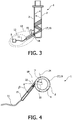
- Figs 3 and 4 show a first embodiment of a heating system 13 according to the invention, which is used for heating up the body 1 of a preform of the kind as depicted in Fig. 1 , i.e. with a tubular shape. It may be understood, however, that preforms can have all kinds of shapes, mainly depending on the intended final shape of the resulting piece after a moulding process which is carried out after the heating of the preform.
- the heating system 13 comprises a light source arrangement 12 and a coupling arrangement 15.
- the light source arrangement 12 includes a light source 9 - in this case a laser diode emitting laser light of a wavelength of 970nm - and an optical fibre 11 which leads the laser light to the coupling arrangement 15.
- the coupling arrangement 15 comprises a silicone end piece 22 (which can be seen in Fig. 4 ) which functions as an optical material similar to an optical fibre.
- a laser light beam 17 is emitted from light source 9 and passes through the optical fibre 11 into the coupling arrangement 15 and further into the body 1 of the preform, thereby entering the body 1 at an entry point 18 on the first surface 2. It is guided along a longer path 19 within the body 1 of the preform, describing a helical path in an upward direction. This causes the light beam 17 to be absorbed by the material of the body 1, which means that the body is heated up.
- the silicone end piece 22 has a shape at its end facing towards the body 1 of the preform which automatically defines an angle ⁇ in the sectional plane of Fig. 3 at which it can be brought into direct physical contact with the body 1 of the preform.
- the coupling arrangement 15 is in contact with the body 1 via its silicone end piece 22 at an angle ⁇ with respect to the normal 20 of the circular shape of the first surface 2 at the entry point 18.
- Angle ⁇ is chosen such that light enters the body 1 within the acceptance angle range of the material of body 1. Therefore, a light beam 17 will stay in the body 1 because of total internal reflection.
- the angle ⁇ at which the light beam is coupled in is unequal 90° with respect to the first surface 2 and with respect to the longitudinal axis of the preform, it is also avoided that the light beam returns to the entry point 18 where it might be coupled out of the body 1 in an uncontrolled manner.
- Fig. 5 shows a heating system comparable to the one described with reference to Figs. 3 and 4 , with the further improvement that several light source arrangements 12 (which can also be considered to be one light source arrangement comprised of several sub-arrangements 12) and coupling arrangements 15 (which can be defined accordingly as one light source arrangement) are provided. It can also be observed that in an upper part of the body 1 of the preform there are three evenly distributed, i.e. evenly spaced, coupling arrangements 15, while in the lower part of the body 1 the coupling arrangements 15 are unevenly spaced and further apart.
- Using such an improved heating system 13 with multiple light source arrangements 12 and coupling arrangements 15, i.e. with several light emitting surfaces it is even easier to guarantee a high precision of the heating process with respect to local differences of the preform such as shape and/or material thickness and or composition. Apart from that, heating can be carried out a lot more rapidly and thus more effectively.
- the coupling arrangement 15 can also be realized in many other ways.
- a droplet of water could be used instead of the silicone end piece.
- Fig. 6 shows an alternative embodiment of a heating system 13 according to the present invention.
- the heating system is integrated in or connected to a preform holder 23 which holds the body 1 of the preform while it is being heated.
- the body 1 of the preform can also be moved by moving the preform holder 23.
- the two light source arrangements 12 of the embodiment are only comprised of two light sources 9, again realized as laser diodes emitting at 970nm. These light sources 9 are attached to the bottom of the preform holder 23 and are each directed into a cavity 16 within the preform holder 23.
- coupling arrangements 21 in the form of lenses which are positioned in such way that the light beam 17 emitted by a light source (arrangement) 9 / 12 is directed right into the bottom of the body 1 of the preform.
- the light beam 17 is coupled into the body 1 in a direction which is exactly perpendicular to the traversal direction T which has been mentioned above, i.e. in parallel with the longitudinal extension of the two surfaces 2, 4.
- This particular form of arrangement of a heating system 13 according to the present invention thus provides a possibility to make guidance of the light beam 17 through the body 1 by means of total internal reflection not essentially necessary.
- total internal reflection may still play a considerable role, because the beams 17 will most probably spread apart, particularly through the effect of the lenses 21, which means that part of the rays of the light beams 17 will be reflected by total internal reflection. Only those rays which are exactly parallel to the longitudinal extension of the two surfaces 2, 4 need not be reflected.
- This embodiment according to the present invention is particularly advantageous insofar as the light source arrangement 12 and the coupling arrangement 21 are integral parts of the preform holder 23 and therefore can be fixedly installed, enabling the coupling angle at which the light beam 17 is coupled into the body to be accurately predetermined for a longer period of time without any further ado.
- water can be inserted into the preform holder 23 to provide direct physical contact between the body 1 of the preform and the preform holder.
- water would serve as a coupling medium and hence as part of a coupling arrangement.
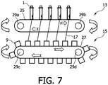
- Fig. 7 shows an embodiment according to the invention using two production lines 25, 27. Both production lines 25 and 27 are moved simultaneously along rolls 29a, 29b and 29c, 29d, respectively. While the first production line 25 moves bodies 1 of preforms, the second production line 27 moves light sources 9 in parallel.
- the arrangement of the heating system 13 is based on the principle of the invention as depicted in Fig. 3 , i.e. coupling a laser beam 17 into a body of a preform from a side and at a suitable angle which is in the acceptance angle range of the material of the body 1.
- the coupling arrangement 15 exists only in the sense that the light beams 17 are emitted at a certain angle with respect to the bodies 1 of the preforms, which is realized by the simultaneous movement of the light sources 9 together with the respective production line 27.
- the second production line 27 and a control unit (not shown) which guarantees the simultaneous movement of the second production line 27 and the first production line 25 constitutes the coupling arrangement 15.
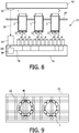
- Fig. 8 shows another embodiment of the present invention, in which the bodies 1 are moved along a route. In this case, they are transported by means of a (symbolized) transport system 37.
- the bodies 1 are moved in between a top side 42 and a bottom side 41 of the heating system 13.
- On the top side there is attached a light ray transmitter 31, while at the corresponding end of the bottom side 41, there is positioned a light ray receiver 33.
- a control device in the form of a control circuit 39 which receives sensing signals SS, make up a photoelectric barrier. This barrier is used for sensing when a body 1 enters the heating system 1.
- the control circuit 39 triggers triggering signals TS to light sources 9 which are positioned on the bottom side 41 and directed towards the top side 42.
- the triggering signals TS will trigger a light emission from those light sources 9 above which a body 1 of a preform is currently positioned.
- a directed light beam 17 is sent deliberately in the direction of the preforms.
- the heating system 13 may be realized by a bottom side 41 shaped like a basin in which water or another suitable liquid is stored as a coupling medium.
- the light sources 9 may be arranged below a transparent part of the basin.
- the cross section of the basin can be realized as depicted in principle in Fig. 6 with respect to the preform holder.
- the transport system 37 may be realized e.g. by moving rubber rolls, which initiate a rolling movement of the preforms, such that the preforms are rotated and every point of the side wall of every preform is exposed along its circumference to light beams from the light sources 9 for a sufficient time period during the movement of the preform along the production line.
- Fig. 9 shows in a top view how such a bottom side 41 can be realized advantageously according to a second embodiment.
- the light sources 9 (see Fig. 8 ) are arranged in an array over which bodies 1 of preforms are moved. Only the light sources 9, over which a preform body is currently positioned are activated. Therefore, there is a distinction between inactive light sources 43 and activated light sources 45. Upon moving the preforms along their path, different light sources 9 will be activated according to the triggering signals TS.
- a “unit” can comprise a number of units, unless otherwise stated. It is especially noted that "a number of light beams” may be made up of a single light beam or a plurality of light beams.
Landscapes
- Physics & Mathematics (AREA)
- Thermal Sciences (AREA)
- Engineering & Computer Science (AREA)
- Mechanical Engineering (AREA)
- Blow-Moulding Or Thermoforming Of Plastics Or The Like (AREA)
Priority Applications (1)
| Application Number | Priority Date | Filing Date | Title |
|---|---|---|---|
| EP10717806.3A EP2421690B1 (en) | 2009-04-21 | 2010-04-19 | Heating system and method of heating a body of a preform |
Applications Claiming Priority (3)
| Application Number | Priority Date | Filing Date | Title |
|---|---|---|---|
| EP09158329 | 2009-04-21 | ||
| PCT/IB2010/051684 WO2010122469A1 (en) | 2009-04-21 | 2010-04-19 | Heating system and method of heating a body of a preform |
| EP10717806.3A EP2421690B1 (en) | 2009-04-21 | 2010-04-19 | Heating system and method of heating a body of a preform |
Publications (2)
| Publication Number | Publication Date |
|---|---|
| EP2421690A1 EP2421690A1 (en) | 2012-02-29 |
| EP2421690B1 true EP2421690B1 (en) | 2018-03-21 |
Family
ID=42668819
Family Applications (1)
| Application Number | Title | Priority Date | Filing Date |
|---|---|---|---|
| EP10717806.3A Active EP2421690B1 (en) | 2009-04-21 | 2010-04-19 | Heating system and method of heating a body of a preform |
Country Status (5)
| Country | Link |
|---|---|
| US (1) | US9162373B2 (enExample) |
| EP (1) | EP2421690B1 (enExample) |
| JP (1) | JP5710592B2 (enExample) |
| CN (1) | CN102438806B (enExample) |
| WO (1) | WO2010122469A1 (enExample) |
Families Citing this family (7)
| Publication number | Priority date | Publication date | Assignee | Title |
|---|---|---|---|---|
| IT1402720B1 (it) * | 2010-11-19 | 2013-09-18 | Sacmi | Apparato per il riscaldamento di preforme in materiale termoplastico. |
| JP6021685B2 (ja) * | 2013-02-22 | 2016-11-09 | 三菱重工食品包装機械株式会社 | プリフォーム加熱装置 |
| FR3018724B1 (fr) * | 2014-03-19 | 2016-12-09 | Sidel Participations | Unite de traitement d'ebauches equipee d'une section de confinement optique a parois convergentes |
| DE102014105675A1 (de) * | 2014-04-23 | 2015-11-12 | Krones Aktiengesellschaft | Vorrichtung und Verfahren zum Erwärmen von Kunststoffvorformlingen |
| FR3094663A1 (fr) * | 2019-04-04 | 2020-10-09 | Sidel Participations | Procédé d’orientation d’une préforme |
| JP7518599B2 (ja) * | 2020-05-29 | 2024-07-18 | 株式会社吉野工業所 | プリフォームの加熱方法 |
| CN115534277A (zh) * | 2022-09-27 | 2022-12-30 | 江苏新美星包装机械股份有限公司 | 一种塑料预型件的加热装置及加热方法 |
Family Cites Families (22)
| Publication number | Priority date | Publication date | Assignee | Title |
|---|---|---|---|---|
| GB1483619A (en) * | 1974-02-14 | 1977-08-24 | Heidenreich & Harbeck Gmbh | Method and apparatus for heating components of synthetic thermoplastics material |
| US4079104A (en) * | 1976-04-16 | 1978-03-14 | Owens-Illinois, Inc. | Method for heating plastic articles |
| US4656325A (en) * | 1984-02-15 | 1987-04-07 | Keefer Richard M | Microwave heating package and method |
| US4894509A (en) * | 1988-12-13 | 1990-01-16 | International Business Machines Corporation | Laser assisted heater bar for multiple lead attachment |
| DE69021377T2 (de) * | 1989-12-12 | 1996-01-25 | Kobe Steel Ltd | VERFAHREN ZUM FORMEN EINES VORGEFORMTEN KöRPERS AUS FASERVERSTÄRKTEM VERBUNDMATERIAL. |
| US5428658A (en) * | 1994-01-21 | 1995-06-27 | Photoelectron Corporation | X-ray source with flexible probe |
| USH1911H (en) | 1992-07-01 | 2000-11-07 | The United States Of America As Represented By The Secretary Of The Air Force | Curing optical material in a plane optical resonant cavity |
| US5540350A (en) | 1995-02-16 | 1996-07-30 | Mallory Industries Inc. | Splash/slosh guard for drinking vessels |
| FR2732924B1 (fr) * | 1995-04-12 | 1997-06-13 | Sidel Sa | Procede et dispositif de chauffage selectif d'une preforme de recipient |
| US5780524A (en) * | 1996-05-14 | 1998-07-14 | Olsen; Don E. | Micro heating apparatus for synthetic fibers and related methods |
| US6361301B1 (en) * | 2000-02-21 | 2002-03-26 | Plastipak Packaging, Inc. | Heater assembly for blow molding plastic preforms |
| AU2001255284A1 (en) * | 2000-04-11 | 2001-10-23 | Branson Ultrasonics Corp. | Light guide for laser welding |
| US6480573B1 (en) * | 2001-12-04 | 2002-11-12 | Photoelectron Corporation | Therapeutic radiation source with increased cathode efficiency |
| FR2876943B1 (fr) * | 2004-10-22 | 2008-08-15 | Sidel Sas | Procede et dispositif de chauffage d'ebauches en matiere thermoplastique |
| FR2878185B1 (fr) * | 2004-11-22 | 2008-11-07 | Sidel Sas | Procede de fabrication de recipients comprenant une etape de chauffe au moyen d'un faisceau de rayonnement electromagnetique coherent |
| US10857722B2 (en) | 2004-12-03 | 2020-12-08 | Pressco Ip Llc | Method and system for laser-based, wavelength specific infrared irradiation treatment |
| CN101130275A (zh) * | 2006-08-22 | 2008-02-27 | 东莞佳鸿机械制造有限公司 | 吹塑机的加热灯箱 |
| WO2008073263A1 (en) * | 2006-12-07 | 2008-06-19 | Ams Research Corporation | Side fire optical device for laterally redirecting high power electromagnetic energy |
| ATE516127T1 (de) * | 2006-12-19 | 2011-07-15 | Koninkl Philips Electronics Nv | System und verfahren zum erwärmen von objekten in einer produktionslinie |
| FR2915418B1 (fr) * | 2007-04-25 | 2012-11-16 | Sidel Participations | Procede de chauffe d'ebauches pour la fabrication de recipients |
| FR2917005B1 (fr) * | 2007-06-11 | 2009-08-28 | Sidel Participations | Installation de chauffage des corps de preformes pour le soufflage de recipients |
| US20120043677A1 (en) * | 2010-08-23 | 2012-02-23 | Energy Focus, Inc. | Method for Making a Combined Light Coupler and Light Pipe |
-
2010
- 2010-04-19 US US13/264,162 patent/US9162373B2/en active Active
- 2010-04-19 JP JP2012506619A patent/JP5710592B2/ja active Active
- 2010-04-19 EP EP10717806.3A patent/EP2421690B1/en active Active
- 2010-04-19 CN CN201080017729.XA patent/CN102438806B/zh active Active
- 2010-04-19 WO PCT/IB2010/051684 patent/WO2010122469A1/en not_active Ceased
Also Published As
| Publication number | Publication date |
|---|---|
| US20120273480A1 (en) | 2012-11-01 |
| CN102438806B (zh) | 2015-05-27 |
| JP5710592B2 (ja) | 2015-04-30 |
| WO2010122469A1 (en) | 2010-10-28 |
| CN102438806A (zh) | 2012-05-02 |
| EP2421690A1 (en) | 2012-02-29 |
| US9162373B2 (en) | 2015-10-20 |
| JP2012524681A (ja) | 2012-10-18 |
Similar Documents
| Publication | Publication Date | Title |
|---|---|---|
| EP2421690B1 (en) | Heating system and method of heating a body of a preform | |
| EP2139667B1 (en) | Method of heating preforms for the manufacture of containers, and heater device | |
| EP2094460B1 (en) | System for and method of heating objects in a production line | |
| MX2007006152A (es) | Proceso e instalacion de fabricacion de recipientes. | |
| US20140305919A1 (en) | Unit for heat treating container preforms with double walls radiating in a staggered configuration | |
| EP2964446B1 (en) | Heating system for pet-preforms | |
| US9144934B2 (en) | Method of heating a preform, a driving arrangement, a preform heating system and a computer program | |
| ES2902586T3 (es) | Sistema de calentamiento de preformas | |
| US9004896B2 (en) | Oven for plastic preforms with partly transparent radiator | |
| US10137627B2 (en) | Unit for processing blanks provided with an optical confinement section having convergent walls | |
| CN106660256A (zh) | 配有热调节限制件的电磁处理单元 | |
| US7160101B2 (en) | Apparatus for heating a nozzle with radiant energy | |
| US11426921B2 (en) | Preform heating device | |
| IT201900012549A1 (it) | Sistema per il riscaldamento delle preforme | |
| US8840392B2 (en) | Temperature gradient controller device in parts of machines for processing plastic materials | |
| PL243165B1 (pl) | Sposób nagrzewania preform z PET w procesie wytwarzania pojemników, zwłaszcza butelek, oraz piec do stosowania tego sposobu | |
| HK1192057A (en) | Corner-cube irradiation control |
Legal Events
| Date | Code | Title | Description |
|---|---|---|---|
| PUAI | Public reference made under article 153(3) epc to a published international application that has entered the european phase |
Free format text: ORIGINAL CODE: 0009012 |
|
| 17P | Request for examination filed |
Effective date: 20111121 |
|
| AK | Designated contracting states |
Kind code of ref document: A1 Designated state(s): AT BE BG CH CY CZ DE DK EE ES FI FR GB GR HR HU IE IS IT LI LT LU LV MC MK MT NL NO PL PT RO SE SI SK SM TR |
|
| DAX | Request for extension of the european patent (deleted) | ||
| RAP1 | Party data changed (applicant data changed or rights of an application transferred) |
Owner name: PHILIPS INTELLECTUAL PROPERTY & STANDARDS GMBH Owner name: KONINKLIJKE PHILIPS N.V. |
|
| 17Q | First examination report despatched |
Effective date: 20141028 |
|
| RIC1 | Information provided on ipc code assigned before grant |
Ipc: B29C 49/64 20060101ALI20160719BHEP Ipc: B29C 49/06 20060101AFI20160719BHEP Ipc: B29C 35/08 20060101ALN20160719BHEP Ipc: B29B 13/02 20060101ALI20160719BHEP |
|
| GRAP | Despatch of communication of intention to grant a patent |
Free format text: ORIGINAL CODE: EPIDOSNIGR1 |
|
| RIC1 | Information provided on ipc code assigned before grant |
Ipc: B29B 13/02 20060101ALI20170920BHEP Ipc: B29C 49/06 20060101AFI20170920BHEP Ipc: B29C 49/64 20060101ALI20170920BHEP Ipc: B29C 35/08 20060101ALN20170920BHEP |
|
| INTG | Intention to grant announced |
Effective date: 20171010 |
|
| GRAS | Grant fee paid |
Free format text: ORIGINAL CODE: EPIDOSNIGR3 |
|
| GRAA | (expected) grant |
Free format text: ORIGINAL CODE: 0009210 |
|
| AK | Designated contracting states |
Kind code of ref document: B1 Designated state(s): AT BE BG CH CY CZ DE DK EE ES FI FR GB GR HR HU IE IS IT LI LT LU LV MC MK MT NL NO PL PT RO SE SI SK SM TR |
|
| REG | Reference to a national code |
Ref country code: GB Ref legal event code: FG4D |
|
| REG | Reference to a national code |
Ref country code: CH Ref legal event code: EP |
|
| REG | Reference to a national code |
Ref country code: AT Ref legal event code: REF Ref document number: 980623 Country of ref document: AT Kind code of ref document: T Effective date: 20180415 |
|
| REG | Reference to a national code |
Ref country code: IE Ref legal event code: FG4D |
|
| REG | Reference to a national code |
Ref country code: DE Ref legal event code: R096 Ref document number: 602010049291 Country of ref document: DE |
|
| REG | Reference to a national code |
Ref country code: FR Ref legal event code: PLFP Year of fee payment: 9 |
|
| REG | Reference to a national code |
Ref country code: NL Ref legal event code: MP Effective date: 20180321 |
|
| PG25 | Lapsed in a contracting state [announced via postgrant information from national office to epo] |
Ref country code: FI Free format text: LAPSE BECAUSE OF FAILURE TO SUBMIT A TRANSLATION OF THE DESCRIPTION OR TO PAY THE FEE WITHIN THE PRESCRIBED TIME-LIMIT Effective date: 20180321 Ref country code: NO Free format text: LAPSE BECAUSE OF FAILURE TO SUBMIT A TRANSLATION OF THE DESCRIPTION OR TO PAY THE FEE WITHIN THE PRESCRIBED TIME-LIMIT Effective date: 20180621 Ref country code: HR Free format text: LAPSE BECAUSE OF FAILURE TO SUBMIT A TRANSLATION OF THE DESCRIPTION OR TO PAY THE FEE WITHIN THE PRESCRIBED TIME-LIMIT Effective date: 20180321 Ref country code: CY Free format text: LAPSE BECAUSE OF FAILURE TO SUBMIT A TRANSLATION OF THE DESCRIPTION OR TO PAY THE FEE WITHIN THE PRESCRIBED TIME-LIMIT Effective date: 20180321 Ref country code: LT Free format text: LAPSE BECAUSE OF FAILURE TO SUBMIT A TRANSLATION OF THE DESCRIPTION OR TO PAY THE FEE WITHIN THE PRESCRIBED TIME-LIMIT Effective date: 20180321 |
|
| REG | Reference to a national code |
Ref country code: LT Ref legal event code: MG4D |
|
| REG | Reference to a national code |
Ref country code: AT Ref legal event code: MK05 Ref document number: 980623 Country of ref document: AT Kind code of ref document: T Effective date: 20180321 |
|
| PG25 | Lapsed in a contracting state [announced via postgrant information from national office to epo] |
Ref country code: BG Free format text: LAPSE BECAUSE OF FAILURE TO SUBMIT A TRANSLATION OF THE DESCRIPTION OR TO PAY THE FEE WITHIN THE PRESCRIBED TIME-LIMIT Effective date: 20180621 Ref country code: GR Free format text: LAPSE BECAUSE OF FAILURE TO SUBMIT A TRANSLATION OF THE DESCRIPTION OR TO PAY THE FEE WITHIN THE PRESCRIBED TIME-LIMIT Effective date: 20180622 Ref country code: SE Free format text: LAPSE BECAUSE OF FAILURE TO SUBMIT A TRANSLATION OF THE DESCRIPTION OR TO PAY THE FEE WITHIN THE PRESCRIBED TIME-LIMIT Effective date: 20180321 Ref country code: LV Free format text: LAPSE BECAUSE OF FAILURE TO SUBMIT A TRANSLATION OF THE DESCRIPTION OR TO PAY THE FEE WITHIN THE PRESCRIBED TIME-LIMIT Effective date: 20180321 |
|
| PG25 | Lapsed in a contracting state [announced via postgrant information from national office to epo] |
Ref country code: RO Free format text: LAPSE BECAUSE OF FAILURE TO SUBMIT A TRANSLATION OF THE DESCRIPTION OR TO PAY THE FEE WITHIN THE PRESCRIBED TIME-LIMIT Effective date: 20180321 Ref country code: EE Free format text: LAPSE BECAUSE OF FAILURE TO SUBMIT A TRANSLATION OF THE DESCRIPTION OR TO PAY THE FEE WITHIN THE PRESCRIBED TIME-LIMIT Effective date: 20180321 Ref country code: IT Free format text: LAPSE BECAUSE OF FAILURE TO SUBMIT A TRANSLATION OF THE DESCRIPTION OR TO PAY THE FEE WITHIN THE PRESCRIBED TIME-LIMIT Effective date: 20180321 Ref country code: ES Free format text: LAPSE BECAUSE OF FAILURE TO SUBMIT A TRANSLATION OF THE DESCRIPTION OR TO PAY THE FEE WITHIN THE PRESCRIBED TIME-LIMIT Effective date: 20180321 Ref country code: NL Free format text: LAPSE BECAUSE OF FAILURE TO SUBMIT A TRANSLATION OF THE DESCRIPTION OR TO PAY THE FEE WITHIN THE PRESCRIBED TIME-LIMIT Effective date: 20180321 Ref country code: PL Free format text: LAPSE BECAUSE OF FAILURE TO SUBMIT A TRANSLATION OF THE DESCRIPTION OR TO PAY THE FEE WITHIN THE PRESCRIBED TIME-LIMIT Effective date: 20180321 |
|
| PG25 | Lapsed in a contracting state [announced via postgrant information from national office to epo] |
Ref country code: SK Free format text: LAPSE BECAUSE OF FAILURE TO SUBMIT A TRANSLATION OF THE DESCRIPTION OR TO PAY THE FEE WITHIN THE PRESCRIBED TIME-LIMIT Effective date: 20180321 Ref country code: CZ Free format text: LAPSE BECAUSE OF FAILURE TO SUBMIT A TRANSLATION OF THE DESCRIPTION OR TO PAY THE FEE WITHIN THE PRESCRIBED TIME-LIMIT Effective date: 20180321 Ref country code: SM Free format text: LAPSE BECAUSE OF FAILURE TO SUBMIT A TRANSLATION OF THE DESCRIPTION OR TO PAY THE FEE WITHIN THE PRESCRIBED TIME-LIMIT Effective date: 20180321 Ref country code: AT Free format text: LAPSE BECAUSE OF FAILURE TO SUBMIT A TRANSLATION OF THE DESCRIPTION OR TO PAY THE FEE WITHIN THE PRESCRIBED TIME-LIMIT Effective date: 20180321 |
|
| REG | Reference to a national code |
Ref country code: CH Ref legal event code: PL |
|
| REG | Reference to a national code |
Ref country code: BE Ref legal event code: MM Effective date: 20180430 |
|
| PG25 | Lapsed in a contracting state [announced via postgrant information from national office to epo] |
Ref country code: PT Free format text: LAPSE BECAUSE OF FAILURE TO SUBMIT A TRANSLATION OF THE DESCRIPTION OR TO PAY THE FEE WITHIN THE PRESCRIBED TIME-LIMIT Effective date: 20180723 |
|
| REG | Reference to a national code |
Ref country code: DE Ref legal event code: R097 Ref document number: 602010049291 Country of ref document: DE |
|
| REG | Reference to a national code |
Ref country code: IE Ref legal event code: MM4A |
|
| PLBE | No opposition filed within time limit |
Free format text: ORIGINAL CODE: 0009261 |
|
| STAA | Information on the status of an ep patent application or granted ep patent |
Free format text: STATUS: NO OPPOSITION FILED WITHIN TIME LIMIT |
|
| PG25 | Lapsed in a contracting state [announced via postgrant information from national office to epo] |
Ref country code: DK Free format text: LAPSE BECAUSE OF FAILURE TO SUBMIT A TRANSLATION OF THE DESCRIPTION OR TO PAY THE FEE WITHIN THE PRESCRIBED TIME-LIMIT Effective date: 20180321 Ref country code: LU Free format text: LAPSE BECAUSE OF NON-PAYMENT OF DUE FEES Effective date: 20180419 Ref country code: MC Free format text: LAPSE BECAUSE OF FAILURE TO SUBMIT A TRANSLATION OF THE DESCRIPTION OR TO PAY THE FEE WITHIN THE PRESCRIBED TIME-LIMIT Effective date: 20180321 |
|
| REG | Reference to a national code |
Ref country code: DE Ref legal event code: R081 Ref document number: 602010049291 Country of ref document: DE Owner name: PHILIPS GMBH, DE Free format text: FORMER OWNER: PHILIPS INTELLECTUAL PROPERTY & STANDARDS GMBH, 20099 HAMBURG, DE |
|
| 26N | No opposition filed |
Effective date: 20190102 |
|
| PG25 | Lapsed in a contracting state [announced via postgrant information from national office to epo] |
Ref country code: CH Free format text: LAPSE BECAUSE OF NON-PAYMENT OF DUE FEES Effective date: 20180430 Ref country code: LI Free format text: LAPSE BECAUSE OF NON-PAYMENT OF DUE FEES Effective date: 20180430 Ref country code: BE Free format text: LAPSE BECAUSE OF NON-PAYMENT OF DUE FEES Effective date: 20180430 |
|
| PG25 | Lapsed in a contracting state [announced via postgrant information from national office to epo] |
Ref country code: IE Free format text: LAPSE BECAUSE OF NON-PAYMENT OF DUE FEES Effective date: 20180419 |
|
| PG25 | Lapsed in a contracting state [announced via postgrant information from national office to epo] |
Ref country code: SI Free format text: LAPSE BECAUSE OF FAILURE TO SUBMIT A TRANSLATION OF THE DESCRIPTION OR TO PAY THE FEE WITHIN THE PRESCRIBED TIME-LIMIT Effective date: 20180321 |
|
| PG25 | Lapsed in a contracting state [announced via postgrant information from national office to epo] |
Ref country code: MT Free format text: LAPSE BECAUSE OF NON-PAYMENT OF DUE FEES Effective date: 20180419 |
|
| PG25 | Lapsed in a contracting state [announced via postgrant information from national office to epo] |
Ref country code: TR Free format text: LAPSE BECAUSE OF FAILURE TO SUBMIT A TRANSLATION OF THE DESCRIPTION OR TO PAY THE FEE WITHIN THE PRESCRIBED TIME-LIMIT Effective date: 20180321 |
|
| PG25 | Lapsed in a contracting state [announced via postgrant information from national office to epo] |
Ref country code: HU Free format text: LAPSE BECAUSE OF FAILURE TO SUBMIT A TRANSLATION OF THE DESCRIPTION OR TO PAY THE FEE WITHIN THE PRESCRIBED TIME-LIMIT; INVALID AB INITIO Effective date: 20100419 |
|
| PG25 | Lapsed in a contracting state [announced via postgrant information from national office to epo] |
Ref country code: MK Free format text: LAPSE BECAUSE OF NON-PAYMENT OF DUE FEES Effective date: 20180321 |
|
| PG25 | Lapsed in a contracting state [announced via postgrant information from national office to epo] |
Ref country code: IS Free format text: LAPSE BECAUSE OF FAILURE TO SUBMIT A TRANSLATION OF THE DESCRIPTION OR TO PAY THE FEE WITHIN THE PRESCRIBED TIME-LIMIT Effective date: 20180721 |
|
| PGFP | Annual fee paid to national office [announced via postgrant information from national office to epo] |
Ref country code: DE Payment date: 20250428 Year of fee payment: 16 |
|
| PGFP | Annual fee paid to national office [announced via postgrant information from national office to epo] |
Ref country code: GB Payment date: 20250422 Year of fee payment: 16 |
|
| PGFP | Annual fee paid to national office [announced via postgrant information from national office to epo] |
Ref country code: FR Payment date: 20250424 Year of fee payment: 16 |