EP2421069B1 - Batteriemodul - Google Patents
Batteriemodul Download PDFInfo
- Publication number
- EP2421069B1 EP2421069B1 EP11158617.8A EP11158617A EP2421069B1 EP 2421069 B1 EP2421069 B1 EP 2421069B1 EP 11158617 A EP11158617 A EP 11158617A EP 2421069 B1 EP2421069 B1 EP 2421069B1
- Authority
- EP
- European Patent Office
- Prior art keywords
- end plate
- battery module
- case
- elastic member
- rechargeable batteries
- Prior art date
- Legal status (The legal status is an assumption and is not a legal conclusion. Google has not performed a legal analysis and makes no representation as to the accuracy of the status listed.)
- Active
Links
Images


Classifications
-
- H—ELECTRICITY
- H01—ELECTRIC ELEMENTS
- H01M—PROCESSES OR MEANS, e.g. BATTERIES, FOR THE DIRECT CONVERSION OF CHEMICAL ENERGY INTO ELECTRICAL ENERGY
- H01M10/00—Secondary cells; Manufacture thereof
- H01M10/04—Construction or manufacture in general
- H01M10/0413—Large-sized flat cells or batteries for motive or stationary systems with plate-like electrodes
-
- H—ELECTRICITY
- H01—ELECTRIC ELEMENTS
- H01M—PROCESSES OR MEANS, e.g. BATTERIES, FOR THE DIRECT CONVERSION OF CHEMICAL ENERGY INTO ELECTRICAL ENERGY
- H01M10/00—Secondary cells; Manufacture thereof
- H01M10/04—Construction or manufacture in general
- H01M10/0468—Compression means for stacks of electrodes and separators
-
- H—ELECTRICITY
- H01—ELECTRIC ELEMENTS
- H01M—PROCESSES OR MEANS, e.g. BATTERIES, FOR THE DIRECT CONVERSION OF CHEMICAL ENERGY INTO ELECTRICAL ENERGY
- H01M50/00—Constructional details or processes of manufacture of the non-active parts of electrochemical cells other than fuel cells, e.g. hybrid cells
- H01M50/10—Primary casings; Jackets or wrappings
- H01M50/102—Primary casings; Jackets or wrappings characterised by their shape or physical structure
- H01M50/103—Primary casings; Jackets or wrappings characterised by their shape or physical structure prismatic or rectangular
-
- H—ELECTRICITY
- H01—ELECTRIC ELEMENTS
- H01M—PROCESSES OR MEANS, e.g. BATTERIES, FOR THE DIRECT CONVERSION OF CHEMICAL ENERGY INTO ELECTRICAL ENERGY
- H01M50/00—Constructional details or processes of manufacture of the non-active parts of electrochemical cells other than fuel cells, e.g. hybrid cells
- H01M50/20—Mountings; Secondary casings or frames; Racks, modules or packs; Suspension devices; Shock absorbers; Transport or carrying devices; Holders
- H01M50/204—Racks, modules or packs for multiple batteries or multiple cells
- H01M50/207—Racks, modules or packs for multiple batteries or multiple cells characterised by their shape
- H01M50/209—Racks, modules or packs for multiple batteries or multiple cells characterised by their shape adapted for prismatic or rectangular cells
-
- H—ELECTRICITY
- H01—ELECTRIC ELEMENTS
- H01M—PROCESSES OR MEANS, e.g. BATTERIES, FOR THE DIRECT CONVERSION OF CHEMICAL ENERGY INTO ELECTRICAL ENERGY
- H01M50/00—Constructional details or processes of manufacture of the non-active parts of electrochemical cells other than fuel cells, e.g. hybrid cells
- H01M50/20—Mountings; Secondary casings or frames; Racks, modules or packs; Suspension devices; Shock absorbers; Transport or carrying devices; Holders
- H01M50/262—Mountings; Secondary casings or frames; Racks, modules or packs; Suspension devices; Shock absorbers; Transport or carrying devices; Holders with fastening means, e.g. locks
- H01M50/264—Mountings; Secondary casings or frames; Racks, modules or packs; Suspension devices; Shock absorbers; Transport or carrying devices; Holders with fastening means, e.g. locks for cells or batteries, e.g. straps, tie rods or peripheral frames
-
- H—ELECTRICITY
- H01—ELECTRIC ELEMENTS
- H01M—PROCESSES OR MEANS, e.g. BATTERIES, FOR THE DIRECT CONVERSION OF CHEMICAL ENERGY INTO ELECTRICAL ENERGY
- H01M6/00—Primary cells; Manufacture thereof
- H01M6/42—Grouping of primary cells into batteries
-
- Y—GENERAL TAGGING OF NEW TECHNOLOGICAL DEVELOPMENTS; GENERAL TAGGING OF CROSS-SECTIONAL TECHNOLOGIES SPANNING OVER SEVERAL SECTIONS OF THE IPC; TECHNICAL SUBJECTS COVERED BY FORMER USPC CROSS-REFERENCE ART COLLECTIONS [XRACs] AND DIGESTS
- Y02—TECHNOLOGIES OR APPLICATIONS FOR MITIGATION OR ADAPTATION AGAINST CLIMATE CHANGE
- Y02E—REDUCTION OF GREENHOUSE GAS [GHG] EMISSIONS, RELATED TO ENERGY GENERATION, TRANSMISSION OR DISTRIBUTION
- Y02E60/00—Enabling technologies; Technologies with a potential or indirect contribution to GHG emissions mitigation
- Y02E60/10—Energy storage using batteries
-
- Y—GENERAL TAGGING OF NEW TECHNOLOGICAL DEVELOPMENTS; GENERAL TAGGING OF CROSS-SECTIONAL TECHNOLOGIES SPANNING OVER SEVERAL SECTIONS OF THE IPC; TECHNICAL SUBJECTS COVERED BY FORMER USPC CROSS-REFERENCE ART COLLECTIONS [XRACs] AND DIGESTS
- Y02—TECHNOLOGIES OR APPLICATIONS FOR MITIGATION OR ADAPTATION AGAINST CLIMATE CHANGE
- Y02P—CLIMATE CHANGE MITIGATION TECHNOLOGIES IN THE PRODUCTION OR PROCESSING OF GOODS
- Y02P70/00—Climate change mitigation technologies in the production process for final industrial or consumer products
- Y02P70/50—Manufacturing or production processes characterised by the final manufactured product
Definitions
- aspects of embodiments of the present invention relate to a battery module and, more particularly, to a battery module capable of stably fixing rechargeable batteries.
- a rechargeable battery may be repeatedly charged and discharged.
- Small-capacity rechargeable batteries are used for small portable electronic devices such as mobile phones, laptop computers, and camcorders, while large-capacity batteries are widely used as power sources for driving motors of hybrid vehicles, etc.
- a battery module is generally composed of a plurality of rechargeable batteries connected in series, in which each rechargeable battery may be formed in a cylindrical shape or a polygonal shape.
- Polygonal rechargeable batteries typically include a case, an electrode assembly in which an anode and a cathode are disposed with a separator therebetween, a space in the case where the electrode assembly is disposed, a cap plate sealing the case and having a terminal hole where an electrode terminal is inserted, and an electrode terminal that is electrically connected with the electrode assembly and that protrudes outside the case through the terminal hole.
- the rechargeable batteries are arranged inside the case of the battery module and are fixed by an end plate.
- the arranged rechargeable batteries may be released from the battery module by an external impact, or the connection between the terminals may become loose such that contact is deteriorated.
- the screw when combining the end plate to the case by using a screw or a bolt, the screw is typically inserted in a hole formed in the case and the end plate and rotated, such that the combination thereof is time consuming.
- the screw typically must be made of a metal material to eliminate abrasion of the screw to the end plate.
- a battery module as defined by claim 1 has an improved structure that is capable of stably fixing rechargeable batteries by providing an elastic structure member that is capable of firmly supporting the rechargeable batteries to the end plate.
- a battery module includes a plurality of rechargeable batteries electrically connected to one another; an end plate arranged at an outermost rechargeable battery of the plurality of rechargeable batteries and supporting the plurality of rechargeable batteries; and at least one elastic member at a surface of the end plate facing the outermost rechargeable battery.
- the at least one elastic member may include a pair of elastic members arranged symmetrically.
- the pair of elastic members may be arranged symmetrically right and left with respect to a center line extending in a longitudinal direction (a y-axis direction) and dividing the end plate into right and left portions, or the pair of elastic members may be arranged symmetrically upward and downward with respect to a center line extending in a transverse direction (a z-axis direction) and dividing the end plate into upper and lower portions.
- the surface of the end plate facing the outermost rechargeable battery may have at least one groove receiving the at least one elastic member, and the at least one elastic member may include a flat spring.
- a battery module may further include a case receiving the plurality of rechargeable batteries, the case may include a pair of outer walls facing each other, and the end plate may be coupled to the pair of outer walls.
- the ends of the outer walls of the case may have at least one through-hole, a side of the end plate may have at least one coupling groove corresponding to the at least one through-hole, and the side of the end plate may include at least one fastening member inserted into the at least one through-hole and the at least one coupling groove and coupling the case and the end plate to each other.
- the at least one coupling groove does not include an interior thread
- the at least one fastening member does not include a screw thread
- the at least one fastening member is made of a plastic material.
- the fastening member may include a body inserted in the coupling groove and a head held close to the outside of the case.
- the battery module may further include a cover coupled to an exterior of the case.
- a battery module may further include another end plate arranged at another outermost rechargeable battery of the plurality of rechargeable batteries located at an end of the battery module opposite the outermost rechargeable battery, the another end plate supporting the plurality of rechargeable batteries, and at least one another elastic member at a surface of the another end plate facing the another outermost rechargeable battery.
- each of the at least one elastic member and the at least one another elastic member includes a pair of elastic members arranged symmetrically with respect to a center line extending in a longitudinal direction and dividing the respective end plate into right and left portions.
- the at least one elastic member includes a pair of elastic members arranged symmetrically with respect to a center line extending in a longitudinal direction and dividing the end plate into right and left portions
- the at least one another elastic member includes a pair of elastic members arranged symmetrically with respect to a center line extending in a transverse direction and dividing the another end plate into upper and lower portions.
- the rechargeable batteries are stably fixed, the coupling force between the case and the end plate is improved, and the coupling structure of the case and the end plate is simplified, thereby simplifying the assembly process of the battery module.
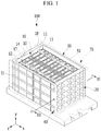
- FIG. 1 is a perspective view of a battery module according to an exemplary embodiment of the present invention
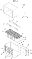
- FIG. 2 is an exploded perspective view of the battery module shown in FIG. 1 .
- a battery module 100 includes a plurality of rechargeable batteries 10 having a positive terminal 11 and a negative terminal 12, an end plate 20 disposed at the outermost one of the rechargeable batteries 10 and supporting the rechargeable batteries 10, and a case 50 receiving the rechargeable batteries 10 and the end plate 20.
- the battery module 100 couples the rechargeable batteries 10 in series.
- the present invention is not limited thereto, and the rechargeable batteries 10 may be connected in parallel, or in a combination of in parallel and in series.
- a case 19 of each of the rechargeable batteries 10 is formed in a polygonal shape
- a cap plate 16 covers an opening of one side of the case 19, and the positive terminal 11 and the negative terminal 12 protrude through the cap plate 16.
- the positive terminal 11 and the negative terminal 12 are electrically connected to positive and negative electrodes, respectively, of an electrode assembly (not shown) housed in the case 19.
- the cap plate 16 may include a vent member 14 that is opened when an internal pressure of the rechargeable battery 10 is increased, and a sealing cap 17 sealing an electrolyte injection opening.
- connection member 13 may be connected to the positive terminal 11 of one of the rechargeable batteries 10, and the negative terminal 12 of a neighboring rechargeable battery 10, such as connecting by using a nut 18.
- the case 50 includes a pair of outer walls 51.
- an upper portion and one end between the pair of outer walls 51 of the case 50 are open.
- the end plate 20 is positioned to face the outermost one of the rechargeable batteries 10 that are arranged in parallel, at one open side of the case 50, thereby supporting the rechargeable batteries 10. Accordingly, the rechargeable batteries 10 that are arranged in parallel are stably supported by the end plate 20 and, as a result, releasing of the rechargeable batteries 10 from the battery arrangement by an external impact or loosening of the connection between the terminals is prevented or substantially prevented.
- the end plate 20 includes an elastic member 40 on a surface of the end plate 20 facing the outside of the outermost rechargeable battery 10.
- the elastic member 40 provides an elastic force to the rechargeable batteries 10 such that the rechargeable batteries 10 received inside the case 50 may be further securely and stably fixed.
- the end plate 20 is combined to an end of the outer wall 51 of the case 50.
- a repulsive force influencing the end plate 20 in the x-axis direction in the case 50 is generated by the elastic force of the elastic member 40 and influences the rechargeable batteries 10.
- the rechargeable batteries 10 may be stably fixed by the friction force between the end plate 20 and the coupling means generated by the repulsive force.
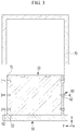
- FIG. 3 is a cross-sectional view of the battery module 100 taken along line III-III of FIG. 1 .
- At least one through-hole 52 is formed at an end of a pair of outer walls 51 of the case 50 corresponding to the end at which the end plate 20 is arranged.
- at least one coupling groove 22 is formed at both sides of the end plate 20 in a direction corresponding to the through-holes 52.
- a fastening member 60 is inserted into the through-hole 52 and the coupling groove 22 such that the end plate 20 is coupled to the outer walls 51 of the case 50.
- a repulsive force applied to the rechargeable batteries 10 is provided in the x-axis direction inside the case 50 by the elastic force of the elastic member 40.
- the fastening member 60 is combined perpendicular to the repulsive force generated by the rechargeable batteries 10 such that the friction force is generated between the end plate 20 and the fastening member 60.
- the end plate 20 and the case 50 may be coupled together due to the friction force.
- the fastening member 60 is inserted into the through-hole 52 and the coupling groove 22 through a simple insertion method, rather than a method of coupling with a screw (i.e. through rotation), the coupling process of the battery module 100 may be simplified, and when coupling the fastening member 60, the through-hole 52, and the coupling groove 22, the degree of freedom of the design to provide a coupling margin for a reaction against an external impact may be increased.
- the fastening member 60 in one embodiment, includes a body 62 inserted in the coupling groove 22 and a head 61 fixed closely to the outside of the case 50 due to the friction force.
- the body 62 in one embodiment, does not have a screw thread.
- the fastening member 60 is not considered regarding abrasion that is generated where an internal thread is present, and, as a result, the fastening member 60 may be made of a plastic material in one embodiment.
- the battery module 100 further includes a cover 70 coupled to the exterior of the case 50.
- the case 50 coupled with the rechargeable batteries 10 is inserted into the cover 70. Since the screw thread is not formed on the body 62 of the fastening member 60 and the fastening member 60 is inserted into the through-hole 52 and the coupling groove 22, if an external impact is applied to the battery module 100, the fastening member 60 may be released outside of the case 50.
- the head 61 of the fastening member 60 is thin such that the case 50 and the cover 70 are very close to each other, and the fastening member 60 is prevented or substantially prevented from being released from the case 50 by the impact.
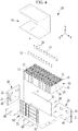
- FIG. 4 is an exploded perspective view of a battery module according to another exemplary embodiment of the present invention.
- a battery module 101 according to another exemplary embodiment, except for a portion of the configuration, has a same structure as the battery module 100 described above and shown in FIGS. 1 and 2 . As such, description of the same components and configurations is omitted.
- the case 50 of the battery module 101 has an open upper portion between a pair of outer walls 51 and two open end portions.
- end plates 20 are positioned to be opposite to, or at opposite outer surfaces of, outermost rechargeable batteries 10 positioned at both ends of the plurality of rechargeable batteries 10 arranged in parallel to the case 50 to support the rechargeable batteries 10.
- the elastic members 40 are respectively formed at the surfaces facing the outermost rechargeable batteries 10 that are positioned at both ends of the plurality of rechargeable batteries 10.
- the repulsive force effected in the x-axis direction inside the case 50 is generated to the end plates 20 that are positioned at both sides of the case 50.
- the rechargeable batteries 10 may be stably maintained through the friction force of the coupling means and the end plates 20 generated by the repulsive force.
- FIGS. 5A and 5B are perspective views of an end plate of a battery module according to an exemplary embodiment of the present invention, the end plate including an elastic member.
- the elastic member 40 is arranged symmetrically to the right and left with respect to a longitudinal (i.e. the y-axis direction) center line 23 dividing a surface of the end plate 20 into right and left portions.
- the end plate 20 is formed with a pair of grooves 21 that are disposed symmetrically to each other to the right and left of the longitudinal (i.e. the y-axis direction) center line 23.
- one end of the elastic member 40 is coupled to one end of the groove 21 to be capable of being rotated (e.g., as a hinge), and the other end of the elastic member 40 is disposed to be released outside the groove 21.
- the elastic member 40 may be fixed through a simple insertion method by forming a coupling groove at the groove 21.
- the elastic member 40 is received at the other end of the groove 21 such that the elastic force is effected to the rechargeable batteries 10 facing the elastic member 40.
- the elastic force effected to the rechargeable batteries 10 functions as the right and left repulsive forces with respect to the central line 23 of the longitudinal direction (i.e. the y-axis direction) of the end plate 20 coupled to the end of the case 50.
- the elastic member 40 may be a flat spring 41.
- the elastic member 40 according to other embodiments of the present invention may include any suitable elastic member for generating the elastic force.
- a central portion of the elastic member 40 facing the groove 21 may be convex (i.e. curved in a direction away from the groove 21), as shown in FIGS. 5A and 5B .
- a central portion of the elastic member 40 facing the groove 21 may be concave.
- the elastic member 40 according to an exemplary embodiment has a structure in which a pair of flat springs are symmetrically disposed. However, in other embodiments, one or three or more elastic members may be appropriately disposed.
- FIGS. 6A and 6B are perspective views of an end plate of a battery module according to another exemplary embodiment of the present invention, the end plate including an elastic member.
- an end plate 30 of a battery module according to an exemplary embodiment of the present invention except for the formation position of a groove 31 receiving an elastic member 40' formed at the end plate 30, is similar to the end plate 20 described above and shown in FIGS. 5A and 5B , and, therefore, description of the same components or structures is omitted.
- the elastic member 40' in one embodiment, is arranged symmetrically with respect to a center line 33 of the transverse direction (i.e. the z-axis direction) dividing the end plate 30 into upper and lower portions.
- the end plate 30 is formed with a pair of grooves 31 that are disposed symmetrically with respect to the center line 33 of the transverse direction (i.e. the z-axis direction).
- one end of the elastic member 40' is coupled to one end of the groove 31 formed at the end plate 30 to be rotatable, such as by a hinge, and the other end of the elastic member 40' is positioned to be released outside the groove 31.
- the elastic member 40' may be fixed through a simple insertion method by forming a coupling groove at the groove 31.
- the elastic member 40' is received at the other end of the groove 31 such that the elastic force is applied to the rechargeable batteries 10 facing the elastic member 40'.
- the elastic force provided to the rechargeable batteries 10 functions as an up and down repulsive force with respect to the central line 33 of the transverse direction (i.e. the z-axis direction) of the end plate 30 coupled to the end of the case 50.
- the elastic member 40' is a flat spring 41'.
- the elastic member 40' may include any other suitable elastic member for generating the elastic force.
- a central portion of the elastic member 40' facing the groove 31 is convex (i.e. curved in a direction away from the groove 31), as shown in FIGS. 6A and 6B .
- a central portion of the elastic member 40' facing the groove 31 may be concave.
- the elastic member 40' has a structure in which the pair of flat springs are disposed in symmetry. However, in other embodiments, one or three or more elastic members may be appropriately disposed.
- the end plate 30 shown in FIG. 6A is coupled to both ends of the pair of outer walls 51 to be opposed to the outermost rechargeable batteries 10 similar to the end plate 20 described above and shown in FIGS. 5A and 5B .
- FIG. 7 is an exploded perspective view of a battery module according to another exemplary embodiment of the present invention.
- a battery module 102 according to another exemplary embodiment of the present invention, except for both ends of a pair of outer walls 51 facing each other and respectively coupled to the end plates 20 and 30, has the same structure as the battery module 101 described above and shown in FIG. 4 , and, therefore, description of the same components and structures is omitted.
- one end of the outer wall 51 of the case 50 is coupled to the end plate 20 such that the elastic member 40 is disposed right and left with respect to the center line 23 of the longitudinal direction (i.e. the y-axis direction).
- the end plate 30 in which the elastic member 40' is disposed upward and downward with respect to the center line 33 of the transverse direction (i.e. the z-axis direction) is coupled to the other end of the outer wall 51 of the case 50.
- the end plate 20 is disposed at one end of the case 50 such that the repulsive force may be applied in the right and left directions of the end plate 20.
- the end plate 30 is disposed at the other end of the case 50 such that the repulsive force may be applied in the upward and downward directions of the end plate 30. Accordingly, the repulsive force is applied in the upward and downward, and right and left directions of the end plates 20 and 30 that are respectively positioned at opposite open ends of the case 50 such that the rechargeable batteries 10 may be further stably fixed to the case 50.
Landscapes
- Chemical & Material Sciences (AREA)
- Chemical Kinetics & Catalysis (AREA)
- Electrochemistry (AREA)
- General Chemical & Material Sciences (AREA)
- Engineering & Computer Science (AREA)
- Manufacturing & Machinery (AREA)
- Battery Mounting, Suspending (AREA)
Claims (13)
- Batteriemodul (100, 101, 102), umfassend:eine Mehrzahl von wiederaufladbaren Batterien (10), die elektrisch miteinander verbunden sind;eine Endplatte (20, 30), die an einer äußersten wiederaufladbaren Batterie der Mehrzahl von wiederaufladbaren Batterien angeordnet ist und die Mehrzahl von wiederaufladbaren Batterien hält; undmindestens ein elastisches Element (40, 40') an einer Oberfläche der Endplatte, die der äußersten wiederaufladbaren Batterie zugewandt ist,ein Gehäuse (50) zum Aufnehmen der Mehrzahl von wiederaufladbaren Batterien (10),dadurch gekennzeichnet, dassdas Gehäuse ein Paar von einander zugewandten Außenwänden (51) aufweist und die Endplatte (20, 30) mit dem Paar von Außenwänden verbunden ist,jeweilige Enden der Außenwände (51) des Gehäuses (50) mindestens eine Durchgangsbohrung (52) aufweisen,eine Seite der Endplatte mindestens eine Verbindungsaussparung (22) aufweist, die der mindestens einen Durchgangsbohrung entspricht, unddie Seite der Endplatte mindestens ein Befestigungselement (60) aufweist, das in die mindestens eine Durchgangsbohrung und die mindestens eine Verbindungsaussparung eingesteckt ist und das Gehäuse und die Endplatte miteinander verbindet.
- Batteriemodul (100, 101, 102) nach Anspruch 1, wobei das mindestens eine elastische Element (40, 40') ein Paar symmetrisch angeordneter elastischer Elemente umfasst.
- Batteriemodul (100, 101, 102) nach Anspruch 2, wobei das Paar elastischer Elemente (40) bezogen auf eine Mittellinie (23), die in einer Längsrichtung verläuft und die Endplatte (20) in einen rechten und linken Abschnitt unterteilt, symmetrisch angeordnet ist.
- Batteriemodul (102) nach Anspruch 2, wobei das Paar elastischer Elemente (40') bezogen auf eine Mittellinie (33), die in einer Querrichtung verläuft und die Endplatte (30) in einen oberen und unteren Abschnitt unterteilt, symmetrisch angeordnet ist.
- Batteriemodul (100, 101, 102) nach einem der vorhergehenden Ansprüche, wobei die Oberfläche der Endplatte (20, 30), die der äußersten wiederaufladbaren Batterie zugewandt ist, mindestens eine Aussparung (21, 31) aufweist, die das mindestens eine elastische Element (40, 40') aufnimmt.
- Batteriemodul (100, 101, 102) nach einem der vorhergehenden Ansprüche, wobei das mindestens eine elastische Element (40, 40') eine Flachfeder (41, 41') umfasst.
- Batteriemodul (100, 101, 102) nach einem der vorhergehenden Ansprüche, wobei die Verbindungsaussparung (22) kein Innengewinde aufweist.
- Batteriemodul (100, 101, 102) nach einem der vorhergehenden Ansprüche, wobei das mindestens eine Befestigungselement (60) kein Schraubgewinde aufweist.
- Batteriemodul (100, 101, 102) nach einem der vorhergehenden Ansprüche, wobei das mindestens eine Befestigungselement (60) aus einem Kunststoff hergestellt ist.
- Batteriemodul (100, 101, 102) nach einem der vorhergehenden Ansprüche, wobei das mindestens eine Befestigungselement (60) umfasst:einen Körper (62), der in die Verbindungsaussparung eingesteckt ist; undeinen Kopf (61), der nahe der Außenseite des Gehäuses gehalten wird.
- Batteriemodul (100, 101, 102) nach einem der vorhergehenden Ansprüche, das ferner eine Abdeckung (70) umfasst, die mit einer Außenfläche des Gehäuses (50) verbunden ist.
- Batteriemodul (101, 102) nach einem der vorhergehenden Ansprüche, das ferner umfasst:eine weitere Endplatte (20, 30), die an einer weiteren äußersten wiederaufladbaren Batterie (10) der Mehrzahl wiederaufladbarer Batterien angeordnet ist, die sich an einem Ende des Batteriemoduls gegenüber der äußersten wiederaufladbaren Batterie befindet, wobei die weitere Endplatte die Mehrzahl von wiederaufladbaren Batterien hält; undmindestens ein weiteres elastisches Element (40, 40') an einer Oberfläche der weiteren Endplatte, die der weiteren äußersten wiederaufladbaren Batterie zugewandt ist.
- Batteriemodul (101) nach Anspruch 12, wobei jedes des mindestens einen elastischen Elements (40) und des mindestens einen weiteren elastischen Elements (40) ein Paar elastischer Elemente umfasst, die bezogen auf eine Mittellinie (23), die in einer Längsrichtung verläuft und die jeweilige Endplatte (20) in einen rechten und linken Abschnitt unterteilt, symmetrisch angeordnet sind.
Applications Claiming Priority (1)
| Application Number | Priority Date | Filing Date | Title |
|---|---|---|---|
| KR1020100079904A KR101173870B1 (ko) | 2010-08-18 | 2010-08-18 | 전지 모듈 |
Publications (2)
| Publication Number | Publication Date |
|---|---|
| EP2421069A1 EP2421069A1 (de) | 2012-02-22 |
| EP2421069B1 true EP2421069B1 (de) | 2017-07-12 |
Family
ID=43920361
Family Applications (1)
| Application Number | Title | Priority Date | Filing Date |
|---|---|---|---|
| EP11158617.8A Active EP2421069B1 (de) | 2010-08-18 | 2011-03-17 | Batteriemodul |
Country Status (3)
| Country | Link |
|---|---|
| US (1) | US8846238B2 (de) |
| EP (1) | EP2421069B1 (de) |
| KR (1) | KR101173870B1 (de) |
Families Citing this family (30)
| Publication number | Priority date | Publication date | Assignee | Title |
|---|---|---|---|---|
| JP6224321B2 (ja) * | 2013-01-11 | 2017-11-01 | フタバ産業株式会社 | 組電池の拘束具、組電池の拘束部材、バッテリ |
| PL3005443T3 (pl) * | 2013-05-24 | 2019-02-28 | Super B International Holding B.V. | Zespół akumulatora i sposób jego wytwarzania |
| KR20150031095A (ko) * | 2013-09-13 | 2015-03-23 | 삼성에스디아이 주식회사 | 배터리 팩 |
| JP6252776B2 (ja) * | 2014-05-07 | 2017-12-27 | 株式会社豊田自動織機 | 電池モジュール |
| WO2015178456A1 (ja) * | 2014-05-22 | 2015-11-26 | 株式会社東芝 | 電池パックおよび電池装置 |
| JP6237479B2 (ja) * | 2014-06-05 | 2017-11-29 | 株式会社豊田自動織機 | 電池モジュール及び電池パック |
| DE102015205485A1 (de) * | 2015-03-26 | 2016-09-29 | Robert Bosch Gmbh | Batteriegehäuse, Batterie mit einem solchen Batteriegehäuse, Plattenelement zur Herstellung eines solchen Batteriegehäuses und Verfahren zur Herstellung eines solchen Batteriegehäuses |
| KR102271384B1 (ko) | 2015-04-15 | 2021-06-29 | 에스케이이노베이션 주식회사 | 이차 전지 팩 |
| KR101948180B1 (ko) * | 2015-04-30 | 2019-02-14 | 주식회사 엘지화학 | 배터리 팩 및 그 제조 방법 |
| US11302973B2 (en) * | 2015-05-19 | 2022-04-12 | Ford Global Technologies, Llc | Battery assembly with multi-function structural assembly |
| KR102154361B1 (ko) | 2015-12-09 | 2020-09-09 | 주식회사 엘지화학 | 엔드 플레이트의 구조가 개선된 배터리 모듈 및 이를 위한 엔드 플레이트 부재 |
| DE102016205920A1 (de) * | 2016-04-08 | 2017-10-12 | Robert Bosch Gmbh | Batteriepack |
| KR102018721B1 (ko) * | 2016-05-31 | 2019-09-09 | 주식회사 엘지화학 | 배터리 모듈 및 이를 포함하는 배터리 팩, 자동차 |
| KR102101906B1 (ko) * | 2016-10-21 | 2020-04-17 | 주식회사 엘지화학 | 조립 가이드 기능의 체결 부재를 포함하는 전지팩 |
| DE102017204531A1 (de) * | 2017-03-17 | 2018-09-20 | Volkswagen Aktiengesellschaft | Anordnung zur Fixierung einer Batteriezelle und/oder eines Zellpakets sowie Batteriegehäuse mit zumindest einer derartigen Anordnung |
| CN109216600B (zh) * | 2017-06-30 | 2021-09-03 | 比亚迪股份有限公司 | 电池模组 |
| US10601006B2 (en) | 2018-04-05 | 2020-03-24 | Ford Global Technologies, Llc | Method and battery assembly for electrified vehicle |
| DE102018114226A1 (de) * | 2018-06-14 | 2019-12-19 | Volkswagen Aktiengesellschaft | Lasttragendes Batteriemodul für ein Kraftfahrzeug und Kraftfahrzeug |
| KR101939617B1 (ko) * | 2018-06-26 | 2019-01-17 | 정상채 | 전기차용 배터리 케이스 |
| DE102018116734B4 (de) * | 2018-07-11 | 2025-08-21 | Dr. Ing. H.C. F. Porsche Aktiengesellschaft | Batteriemodul für ein Kraftfahrzeug |
| CN209730085U (zh) * | 2019-04-30 | 2019-12-03 | 宁德时代新能源科技股份有限公司 | 电池模组 |
| KR102767701B1 (ko) * | 2020-03-06 | 2025-02-12 | 주식회사 엘지에너지솔루션 | 전지 모듈 및 그 제조 방법 |
| KR102767702B1 (ko) * | 2020-03-06 | 2025-02-12 | 주식회사 엘지에너지솔루션 | 전지 모듈 및 그 제조 방법 |
| JP7167103B2 (ja) * | 2020-08-25 | 2022-11-08 | プライムプラネットエナジー&ソリューションズ株式会社 | 蓄電装置およびその製造方法 |
| JP7319953B2 (ja) * | 2020-10-20 | 2023-08-02 | プライムプラネットエナジー&ソリューションズ株式会社 | 蓄電装置 |
| JP7232802B2 (ja) * | 2020-10-20 | 2023-03-03 | プライムプラネットエナジー&ソリューションズ株式会社 | 蓄電装置 |
| DE102020213475A1 (de) * | 2020-10-27 | 2022-04-28 | Robert Bosch Gesellschaft mit beschränkter Haftung | Batteriemodul |
| KR102834536B1 (ko) * | 2021-01-11 | 2025-07-15 | 주식회사 엘지에너지솔루션 | 팽창완화 유닛을 포함하는 전지 모듈 |
| JP7700604B2 (ja) * | 2021-09-24 | 2025-07-01 | トヨタ自動車株式会社 | 蓄電装置 |
| JP2026000130A (ja) * | 2024-06-17 | 2026-01-05 | プライムプラネットエナジー&ソリューションズ株式会社 | 組電池および電池パック |
Family Cites Families (12)
| Publication number | Priority date | Publication date | Assignee | Title |
|---|---|---|---|---|
| US5250371A (en) * | 1991-12-24 | 1993-10-05 | Motorola, Inc. | Weldless surface mounted interconnect |
| KR19990050734A (ko) | 1997-12-17 | 1999-07-05 | 정몽규 | 전기 자동차용 배터리 장착 구조 |
| JP4639583B2 (ja) | 2003-03-06 | 2011-02-23 | トヨタ自動車株式会社 | 燃料電池 |
| JP4749774B2 (ja) * | 2005-06-16 | 2011-08-17 | 本田技研工業株式会社 | 組電池 |
| JP4921340B2 (ja) | 2006-03-28 | 2012-04-25 | 株式会社キャプテックス | 電池モジュール |
| JP5178061B2 (ja) | 2007-06-25 | 2013-04-10 | 株式会社日立製作所 | 燃料電池 |
| JP2009026703A (ja) | 2007-07-23 | 2009-02-05 | Toyota Motor Corp | 組電池の製造方法 |
| US7652886B2 (en) * | 2007-07-31 | 2010-01-26 | Fu Zhun Precision Industry (Shen Zhen) Co., Ltd. | Heat sink assembly having a fastener assembly for fastening the heat sink to an electronic component |
| JP5122898B2 (ja) | 2007-09-26 | 2013-01-16 | トヨタ自動車株式会社 | 蓄電モジュール |
| JP5256683B2 (ja) | 2007-10-17 | 2013-08-07 | パナソニック株式会社 | 積層体の加圧構造 |
| JP2009135024A (ja) | 2007-11-30 | 2009-06-18 | Toyota Motor Corp | 燃料電池 |
| KR100995429B1 (ko) | 2008-10-13 | 2010-11-18 | 삼성에스디아이 주식회사 | 전지 팩 |
-
2010
- 2010-08-18 KR KR1020100079904A patent/KR101173870B1/ko active Active
- 2010-12-01 US US12/958,143 patent/US8846238B2/en active Active
-
2011
- 2011-03-17 EP EP11158617.8A patent/EP2421069B1/de active Active
Non-Patent Citations (1)
| Title |
|---|
| None * |
Also Published As
| Publication number | Publication date |
|---|---|
| EP2421069A1 (de) | 2012-02-22 |
| US20120045686A1 (en) | 2012-02-23 |
| KR20120017296A (ko) | 2012-02-28 |
| US8846238B2 (en) | 2014-09-30 |
| KR101173870B1 (ko) | 2012-08-14 |
Similar Documents
| Publication | Publication Date | Title |
|---|---|---|
| EP2421069B1 (de) | Batteriemodul | |
| EP2793289B1 (de) | Batteriemodul | |
| US10243193B2 (en) | Battery pack | |
| EP3128571B1 (de) | Sekundärbatterie | |
| JP5297421B2 (ja) | 二次電池 | |
| JP6462003B2 (ja) | 安全性及び作動寿命が向上したバッテリーモジュール | |
| US9251986B2 (en) | Rechargeable battery | |
| EP2648243A1 (de) | Batteriemodul | |
| US9293756B2 (en) | Rechargeable battery | |
| EP2390941B1 (de) | Batteriepack | |
| EP3309866A1 (de) | Batteriemodul, batteriepack damit und automobil | |
| EP3297061B1 (de) | Batteriepack | |
| US20140356664A1 (en) | Battery module | |
| KR20120036743A (ko) | 이차 전지 | |
| EP3024064B1 (de) | Sekundärbatterie | |
| KR102066198B1 (ko) | 배터리 팩 | |
| KR101275785B1 (ko) | 이차 전지 | |
| EP3576178A1 (de) | Batteriepack | |
| KR20090126096A (ko) | 전지 팩 | |
| EP4318764B1 (de) | Batteriepack und fahrzeug damit | |
| KR20230025417A (ko) | 배터리 팩 | |
| EP2602841B1 (de) | Batterie | |
| KR20170054881A (ko) | 배터리 모듈 및 이를 포함하는 배터리 팩 | |
| US7485392B2 (en) | Rechargeable battery having impact buffer function | |
| US8445131B2 (en) | Holder case for secondary battery and lithium secondary battery using the same |
Legal Events
| Date | Code | Title | Description |
|---|---|---|---|
| AK | Designated contracting states |
Kind code of ref document: A1 Designated state(s): AL AT BE BG CH CY CZ DE DK EE ES FI FR GB GR HR HU IE IS IT LI LT LU LV MC MK MT NL NO PL PT RO RS SE SI SK SM TR |
|
| AX | Request for extension of the european patent |
Extension state: BA ME |
|
| PUAI | Public reference made under article 153(3) epc to a published international application that has entered the european phase |
Free format text: ORIGINAL CODE: 0009012 |
|
| 17P | Request for examination filed |
Effective date: 20120214 |
|
| RAP1 | Party data changed (applicant data changed or rights of an application transferred) |
Owner name: ROBERT BOSCH GMBH Owner name: SAMSUNG SDI CO., LTD. |
|
| 17Q | First examination report despatched |
Effective date: 20130912 |
|
| GRAP | Despatch of communication of intention to grant a patent |
Free format text: ORIGINAL CODE: EPIDOSNIGR1 |
|
| STAA | Information on the status of an ep patent application or granted ep patent |
Free format text: STATUS: GRANT OF PATENT IS INTENDED |
|
| INTG | Intention to grant announced |
Effective date: 20170217 |
|
| GRAS | Grant fee paid |
Free format text: ORIGINAL CODE: EPIDOSNIGR3 |
|
| GRAA | (expected) grant |
Free format text: ORIGINAL CODE: 0009210 |
|
| STAA | Information on the status of an ep patent application or granted ep patent |
Free format text: STATUS: THE PATENT HAS BEEN GRANTED |
|
| AK | Designated contracting states |
Kind code of ref document: B1 Designated state(s): AL AT BE BG CH CY CZ DE DK EE ES FI FR GB GR HR HU IE IS IT LI LT LU LV MC MK MT NL NO PL PT RO RS SE SI SK SM TR |
|
| REG | Reference to a national code |
Ref country code: GB Ref legal event code: FG4D |
|
| REG | Reference to a national code |
Ref country code: CH Ref legal event code: EP |
|
| REG | Reference to a national code |
Ref country code: AT Ref legal event code: REF Ref document number: 909117 Country of ref document: AT Kind code of ref document: T Effective date: 20170715 |
|
| REG | Reference to a national code |
Ref country code: IE Ref legal event code: FG4D |
|
| REG | Reference to a national code |
Ref country code: DE Ref legal event code: R096 Ref document number: 602011039417 Country of ref document: DE |
|
| REG | Reference to a national code |
Ref country code: NL Ref legal event code: MP Effective date: 20170712 |
|
| REG | Reference to a national code |
Ref country code: LT Ref legal event code: MG4D |
|
| REG | Reference to a national code |
Ref country code: AT Ref legal event code: MK05 Ref document number: 909117 Country of ref document: AT Kind code of ref document: T Effective date: 20170712 |
|
| PG25 | Lapsed in a contracting state [announced via postgrant information from national office to epo] |
Ref country code: AT Free format text: LAPSE BECAUSE OF FAILURE TO SUBMIT A TRANSLATION OF THE DESCRIPTION OR TO PAY THE FEE WITHIN THE PRESCRIBED TIME-LIMIT Effective date: 20170712 Ref country code: NL Free format text: LAPSE BECAUSE OF FAILURE TO SUBMIT A TRANSLATION OF THE DESCRIPTION OR TO PAY THE FEE WITHIN THE PRESCRIBED TIME-LIMIT Effective date: 20170712 Ref country code: HR Free format text: LAPSE BECAUSE OF FAILURE TO SUBMIT A TRANSLATION OF THE DESCRIPTION OR TO PAY THE FEE WITHIN THE PRESCRIBED TIME-LIMIT Effective date: 20170712 Ref country code: SE Free format text: LAPSE BECAUSE OF FAILURE TO SUBMIT A TRANSLATION OF THE DESCRIPTION OR TO PAY THE FEE WITHIN THE PRESCRIBED TIME-LIMIT Effective date: 20170712 Ref country code: NO Free format text: LAPSE BECAUSE OF FAILURE TO SUBMIT A TRANSLATION OF THE DESCRIPTION OR TO PAY THE FEE WITHIN THE PRESCRIBED TIME-LIMIT Effective date: 20171012 Ref country code: FI Free format text: LAPSE BECAUSE OF FAILURE TO SUBMIT A TRANSLATION OF THE DESCRIPTION OR TO PAY THE FEE WITHIN THE PRESCRIBED TIME-LIMIT Effective date: 20170712 Ref country code: LT Free format text: LAPSE BECAUSE OF FAILURE TO SUBMIT A TRANSLATION OF THE DESCRIPTION OR TO PAY THE FEE WITHIN THE PRESCRIBED TIME-LIMIT Effective date: 20170712 |
|
| REG | Reference to a national code |
Ref country code: FR Ref legal event code: PLFP Year of fee payment: 8 |
|
| PG25 | Lapsed in a contracting state [announced via postgrant information from national office to epo] |
Ref country code: BG Free format text: LAPSE BECAUSE OF FAILURE TO SUBMIT A TRANSLATION OF THE DESCRIPTION OR TO PAY THE FEE WITHIN THE PRESCRIBED TIME-LIMIT Effective date: 20171012 Ref country code: GR Free format text: LAPSE BECAUSE OF FAILURE TO SUBMIT A TRANSLATION OF THE DESCRIPTION OR TO PAY THE FEE WITHIN THE PRESCRIBED TIME-LIMIT Effective date: 20171013 Ref country code: LV Free format text: LAPSE BECAUSE OF FAILURE TO SUBMIT A TRANSLATION OF THE DESCRIPTION OR TO PAY THE FEE WITHIN THE PRESCRIBED TIME-LIMIT Effective date: 20170712 Ref country code: IS Free format text: LAPSE BECAUSE OF FAILURE TO SUBMIT A TRANSLATION OF THE DESCRIPTION OR TO PAY THE FEE WITHIN THE PRESCRIBED TIME-LIMIT Effective date: 20171112 Ref country code: RS Free format text: LAPSE BECAUSE OF FAILURE TO SUBMIT A TRANSLATION OF THE DESCRIPTION OR TO PAY THE FEE WITHIN THE PRESCRIBED TIME-LIMIT Effective date: 20170712 Ref country code: ES Free format text: LAPSE BECAUSE OF FAILURE TO SUBMIT A TRANSLATION OF THE DESCRIPTION OR TO PAY THE FEE WITHIN THE PRESCRIBED TIME-LIMIT Effective date: 20170712 Ref country code: PL Free format text: LAPSE BECAUSE OF FAILURE TO SUBMIT A TRANSLATION OF THE DESCRIPTION OR TO PAY THE FEE WITHIN THE PRESCRIBED TIME-LIMIT Effective date: 20170712 |
|
| REG | Reference to a national code |
Ref country code: DE Ref legal event code: R097 Ref document number: 602011039417 Country of ref document: DE |
|
| PG25 | Lapsed in a contracting state [announced via postgrant information from national office to epo] |
Ref country code: CZ Free format text: LAPSE BECAUSE OF FAILURE TO SUBMIT A TRANSLATION OF THE DESCRIPTION OR TO PAY THE FEE WITHIN THE PRESCRIBED TIME-LIMIT Effective date: 20170712 Ref country code: RO Free format text: LAPSE BECAUSE OF FAILURE TO SUBMIT A TRANSLATION OF THE DESCRIPTION OR TO PAY THE FEE WITHIN THE PRESCRIBED TIME-LIMIT Effective date: 20170712 Ref country code: DK Free format text: LAPSE BECAUSE OF FAILURE TO SUBMIT A TRANSLATION OF THE DESCRIPTION OR TO PAY THE FEE WITHIN THE PRESCRIBED TIME-LIMIT Effective date: 20170712 |
|
| PLBE | No opposition filed within time limit |
Free format text: ORIGINAL CODE: 0009261 |
|
| STAA | Information on the status of an ep patent application or granted ep patent |
Free format text: STATUS: NO OPPOSITION FILED WITHIN TIME LIMIT |
|
| PG25 | Lapsed in a contracting state [announced via postgrant information from national office to epo] |
Ref country code: SM Free format text: LAPSE BECAUSE OF FAILURE TO SUBMIT A TRANSLATION OF THE DESCRIPTION OR TO PAY THE FEE WITHIN THE PRESCRIBED TIME-LIMIT Effective date: 20170712 Ref country code: EE Free format text: LAPSE BECAUSE OF FAILURE TO SUBMIT A TRANSLATION OF THE DESCRIPTION OR TO PAY THE FEE WITHIN THE PRESCRIBED TIME-LIMIT Effective date: 20170712 Ref country code: SK Free format text: LAPSE BECAUSE OF FAILURE TO SUBMIT A TRANSLATION OF THE DESCRIPTION OR TO PAY THE FEE WITHIN THE PRESCRIBED TIME-LIMIT Effective date: 20170712 Ref country code: IT Free format text: LAPSE BECAUSE OF FAILURE TO SUBMIT A TRANSLATION OF THE DESCRIPTION OR TO PAY THE FEE WITHIN THE PRESCRIBED TIME-LIMIT Effective date: 20170712 |
|
| 26N | No opposition filed |
Effective date: 20180413 |
|
| PG25 | Lapsed in a contracting state [announced via postgrant information from national office to epo] |
Ref country code: SI Free format text: LAPSE BECAUSE OF FAILURE TO SUBMIT A TRANSLATION OF THE DESCRIPTION OR TO PAY THE FEE WITHIN THE PRESCRIBED TIME-LIMIT Effective date: 20170712 |
|
| REG | Reference to a national code |
Ref country code: CH Ref legal event code: PL |
|
| PG25 | Lapsed in a contracting state [announced via postgrant information from national office to epo] |
Ref country code: MC Free format text: LAPSE BECAUSE OF FAILURE TO SUBMIT A TRANSLATION OF THE DESCRIPTION OR TO PAY THE FEE WITHIN THE PRESCRIBED TIME-LIMIT Effective date: 20170712 |
|
| REG | Reference to a national code |
Ref country code: BE Ref legal event code: MM Effective date: 20180331 |
|
| REG | Reference to a national code |
Ref country code: IE Ref legal event code: MM4A |
|
| PG25 | Lapsed in a contracting state [announced via postgrant information from national office to epo] |
Ref country code: LU Free format text: LAPSE BECAUSE OF NON-PAYMENT OF DUE FEES Effective date: 20180317 |
|
| PG25 | Lapsed in a contracting state [announced via postgrant information from national office to epo] |
Ref country code: IE Free format text: LAPSE BECAUSE OF NON-PAYMENT OF DUE FEES Effective date: 20180317 |
|
| PG25 | Lapsed in a contracting state [announced via postgrant information from national office to epo] |
Ref country code: CH Free format text: LAPSE BECAUSE OF NON-PAYMENT OF DUE FEES Effective date: 20180331 Ref country code: BE Free format text: LAPSE BECAUSE OF NON-PAYMENT OF DUE FEES Effective date: 20180331 Ref country code: LI Free format text: LAPSE BECAUSE OF NON-PAYMENT OF DUE FEES Effective date: 20180331 |
|
| PG25 | Lapsed in a contracting state [announced via postgrant information from national office to epo] |
Ref country code: MT Free format text: LAPSE BECAUSE OF NON-PAYMENT OF DUE FEES Effective date: 20180317 |
|
| PG25 | Lapsed in a contracting state [announced via postgrant information from national office to epo] |
Ref country code: TR Free format text: LAPSE BECAUSE OF FAILURE TO SUBMIT A TRANSLATION OF THE DESCRIPTION OR TO PAY THE FEE WITHIN THE PRESCRIBED TIME-LIMIT Effective date: 20170712 |
|
| PG25 | Lapsed in a contracting state [announced via postgrant information from national office to epo] |
Ref country code: HU Free format text: LAPSE BECAUSE OF FAILURE TO SUBMIT A TRANSLATION OF THE DESCRIPTION OR TO PAY THE FEE WITHIN THE PRESCRIBED TIME-LIMIT; INVALID AB INITIO Effective date: 20110317 Ref country code: PT Free format text: LAPSE BECAUSE OF FAILURE TO SUBMIT A TRANSLATION OF THE DESCRIPTION OR TO PAY THE FEE WITHIN THE PRESCRIBED TIME-LIMIT Effective date: 20170712 |
|
| PG25 | Lapsed in a contracting state [announced via postgrant information from national office to epo] |
Ref country code: CY Free format text: LAPSE BECAUSE OF FAILURE TO SUBMIT A TRANSLATION OF THE DESCRIPTION OR TO PAY THE FEE WITHIN THE PRESCRIBED TIME-LIMIT Effective date: 20170712 Ref country code: MK Free format text: LAPSE BECAUSE OF NON-PAYMENT OF DUE FEES Effective date: 20170712 |
|
| PG25 | Lapsed in a contracting state [announced via postgrant information from national office to epo] |
Ref country code: AL Free format text: LAPSE BECAUSE OF FAILURE TO SUBMIT A TRANSLATION OF THE DESCRIPTION OR TO PAY THE FEE WITHIN THE PRESCRIBED TIME-LIMIT Effective date: 20170712 |
|
| REG | Reference to a national code |
Ref country code: DE Ref legal event code: R079 Ref document number: 602011039417 Country of ref document: DE Free format text: PREVIOUS MAIN CLASS: H01M0002100000 Ipc: H01M0050200000 |
|
| P01 | Opt-out of the competence of the unified patent court (upc) registered |
Effective date: 20230530 |
|
| PGFP | Annual fee paid to national office [announced via postgrant information from national office to epo] |
Ref country code: DE Payment date: 20250305 Year of fee payment: 15 |
|
| PGFP | Annual fee paid to national office [announced via postgrant information from national office to epo] |
Ref country code: FR Payment date: 20250310 Year of fee payment: 15 |
|
| PGFP | Annual fee paid to national office [announced via postgrant information from national office to epo] |
Ref country code: GB Payment date: 20250306 Year of fee payment: 15 |