EP2420879A1 - Driving unit, lens module, and image pickup device - Google Patents
Driving unit, lens module, and image pickup device Download PDFInfo
- Publication number
- EP2420879A1 EP2420879A1 EP20110176581 EP11176581A EP2420879A1 EP 2420879 A1 EP2420879 A1 EP 2420879A1 EP 20110176581 EP20110176581 EP 20110176581 EP 11176581 A EP11176581 A EP 11176581A EP 2420879 A1 EP2420879 A1 EP 2420879A1
- Authority
- EP
- European Patent Office
- Prior art keywords
- voltage
- polymer actuator
- driving unit
- unit according
- driving
- Prior art date
- Legal status (The legal status is an assumption and is not a legal conclusion. Google has not performed a legal analysis and makes no representation as to the accuracy of the status listed.)
- Withdrawn
Links
Images


Classifications
-
- F—MECHANICAL ENGINEERING; LIGHTING; HEATING; WEAPONS; BLASTING
- F03—MACHINES OR ENGINES FOR LIQUIDS; WIND, SPRING, OR WEIGHT MOTORS; PRODUCING MECHANICAL POWER OR A REACTIVE PROPULSIVE THRUST, NOT OTHERWISE PROVIDED FOR
- F03G—SPRING, WEIGHT, INERTIA OR LIKE MOTORS; MECHANICAL-POWER PRODUCING DEVICES OR MECHANISMS, NOT OTHERWISE PROVIDED FOR OR USING ENERGY SOURCES NOT OTHERWISE PROVIDED FOR
- F03G7/00—Mechanical-power-producing mechanisms, not otherwise provided for or using energy sources not otherwise provided for
- F03G7/005—Electro-chemical actuators; Actuators having a material for absorbing or desorbing gas, e.g. a metal hydride; Actuators using the difference in osmotic pressure between fluids; Actuators with elements stretchable when contacted with liquid rich in ions, with UV light, with a salt solution
-
- G—PHYSICS
- G02—OPTICS
- G02B—OPTICAL ELEMENTS, SYSTEMS OR APPARATUS
- G02B7/00—Mountings, adjusting means, or light-tight connections, for optical elements
- G02B7/02—Mountings, adjusting means, or light-tight connections, for optical elements for lenses
- G02B7/04—Mountings, adjusting means, or light-tight connections, for optical elements for lenses with mechanism for focusing or varying magnification
- G02B7/10—Mountings, adjusting means, or light-tight connections, for optical elements for lenses with mechanism for focusing or varying magnification by relative axial movement of several lenses, e.g. of varifocal objective lens
- G02B7/102—Mountings, adjusting means, or light-tight connections, for optical elements for lenses with mechanism for focusing or varying magnification by relative axial movement of several lenses, e.g. of varifocal objective lens controlled by a microcomputer
-
- F—MECHANICAL ENGINEERING; LIGHTING; HEATING; WEAPONS; BLASTING
- F03—MACHINES OR ENGINES FOR LIQUIDS; WIND, SPRING, OR WEIGHT MOTORS; PRODUCING MECHANICAL POWER OR A REACTIVE PROPULSIVE THRUST, NOT OTHERWISE PROVIDED FOR
- F03G—SPRING, WEIGHT, INERTIA OR LIKE MOTORS; MECHANICAL-POWER PRODUCING DEVICES OR MECHANISMS, NOT OTHERWISE PROVIDED FOR OR USING ENERGY SOURCES NOT OTHERWISE PROVIDED FOR
- F03G7/00—Mechanical-power-producing mechanisms, not otherwise provided for or using energy sources not otherwise provided for
- F03G7/008—Mechanical-power-producing mechanisms, not otherwise provided for or using energy sources not otherwise provided for characterised by the actuating element
- F03G7/012—Electro-chemical actuators
- F03G7/0121—Electroactive polymers
-
- G—PHYSICS
- G02—OPTICS
- G02B—OPTICAL ELEMENTS, SYSTEMS OR APPARATUS
- G02B13/00—Optical objectives specially designed for the purposes specified below
- G02B13/001—Miniaturised objectives for electronic devices, e.g. portable telephones, webcams, PDAs, small digital cameras
- G02B13/0015—Miniaturised objectives for electronic devices, e.g. portable telephones, webcams, PDAs, small digital cameras characterised by the lens design
- G02B13/002—Miniaturised objectives for electronic devices, e.g. portable telephones, webcams, PDAs, small digital cameras characterised by the lens design having at least one aspherical surface
- G02B13/0025—Miniaturised objectives for electronic devices, e.g. portable telephones, webcams, PDAs, small digital cameras characterised by the lens design having at least one aspherical surface having one lens only
-
- G—PHYSICS
- G02—OPTICS
- G02B—OPTICAL ELEMENTS, SYSTEMS OR APPARATUS
- G02B7/00—Mountings, adjusting means, or light-tight connections, for optical elements
- G02B7/02—Mountings, adjusting means, or light-tight connections, for optical elements for lenses
- G02B7/026—Mountings, adjusting means, or light-tight connections, for optical elements for lenses using retaining rings or springs
-
- G—PHYSICS
- G03—PHOTOGRAPHY; CINEMATOGRAPHY; ANALOGOUS TECHNIQUES USING WAVES OTHER THAN OPTICAL WAVES; ELECTROGRAPHY; HOLOGRAPHY
- G03B—APPARATUS OR ARRANGEMENTS FOR TAKING PHOTOGRAPHS OR FOR PROJECTING OR VIEWING THEM; APPARATUS OR ARRANGEMENTS EMPLOYING ANALOGOUS TECHNIQUES USING WAVES OTHER THAN OPTICAL WAVES; ACCESSORIES THEREFOR
- G03B3/00—Focusing arrangements of general interest for cameras, projectors or printers
- G03B3/10—Power-operated focusing
-
- H—ELECTRICITY
- H04—ELECTRIC COMMUNICATION TECHNIQUE
- H04N—PICTORIAL COMMUNICATION, e.g. TELEVISION
- H04N23/00—Cameras or camera modules comprising electronic image sensors; Control thereof
-
- H—ELECTRICITY
- H10—SEMICONDUCTOR DEVICES; ELECTRIC SOLID-STATE DEVICES NOT OTHERWISE PROVIDED FOR
- H10N—ELECTRIC SOLID-STATE DEVICES NOT OTHERWISE PROVIDED FOR
- H10N30/00—Piezoelectric or electrostrictive devices
- H10N30/20—Piezoelectric or electrostrictive devices with electrical input and mechanical output, e.g. functioning as actuators or vibrators
- H10N30/204—Piezoelectric or electrostrictive devices with electrical input and mechanical output, e.g. functioning as actuators or vibrators using bending displacement, e.g. unimorph, bimorph or multimorph cantilever or membrane benders
- H10N30/2041—Beam type
- H10N30/2042—Cantilevers, i.e. having one fixed end
- H10N30/2043—Cantilevers, i.e. having one fixed end connected at their free ends, e.g. parallelogram type
-
- H—ELECTRICITY
- H10—SEMICONDUCTOR DEVICES; ELECTRIC SOLID-STATE DEVICES NOT OTHERWISE PROVIDED FOR
- H10N—ELECTRIC SOLID-STATE DEVICES NOT OTHERWISE PROVIDED FOR
- H10N30/00—Piezoelectric or electrostrictive devices
- H10N30/80—Constructional details
- H10N30/85—Piezoelectric or electrostrictive active materials
- H10N30/857—Macromolecular compositions
Definitions
- the present disclosure relates to a driving unit using a polymer actuator element, and a lens module as well as an image pickup device with such a driving unit.
- portable electronic devices such as a portable telephone, and a personal computer (PC), or a PDA (Personal Digital Assistant) have become remarkably multifunctional, and a portable electronic device equipped with a lens module thereby having an image pickup function has become common.
- focusing and zooming are performed by moving a lens in the lens module to an optical axis direction.
- the polymer actuator element is an element in which, for example, an ion exchange resin film is interposed between a pair of electrodes. In this polymer actuator element, the ion exchange resin film is displaced in a direction orthogonal to a film surface, due to occurrence of a potential difference between the pair of electrodes.
- a driving unit that may improve characteristics in a low temperature environment while implementing downsizing, and a lens module as well as an image pickup device with such a driving unit.
- a driving unit including one or a plurality of polymer actuator elements, and a voltage supply section supplying a driving voltage and a heating voltage to the polymer actuator element.
- a lens module including a lens, and the above-described driving unit driving the lens.
- an image pickup device including a lens, an image pickup element acquiring an image pickup signal of image formation by the lens, and the above-described driving unit driving the lens.
- the heating voltage is supplied to the polymer actuator element.
- the temperature of the element increases due to heat generation by the polymer actuator element itself, without a dedicated heat source being provided outside separately.
- the heating voltage is supplied to the polymer actuator element. Therefore, it is possible to increase the temperature of the element by heat generation of the polymer actuator element itself, and improve the working speed and the like of the element in a low temperature environment, without providing an external dedicated heat source separately. Accordingly, it is possible to improve characteristics in the low temperature environment, while implementing downsizing.
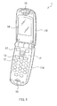
- FIG. 1 and FIG. 2 are perspective diagrams illustrating a schematic structure of a portable telephone (a portable telephone 1) with an image pickup function, as an example of an electronic device with an image pickup device (an image pickup device 2 to be described later) according to an embodiment of the present disclosure.
- a portable telephone a portable telephone 1 with an image pickup function
- two housings 11A and 11B are foldably coupled together through a hinge mechanism not illustrated.
- various operation keys 12 are disposed, and a microphone 13 is disposed below the operation keys 12.
- the operation keys 12 are intended to receive predetermined operation by a user and thereby input information.
- the microphone 13 is intended to input voice of the user during a call and the like.
- a display section 14 using a liquid-crystal display panel or the like is disposed in a surface on one side of the housing 11B, and a speaker 15 is disposed at an upper end thereof.
- the display section 14 displays various kinds of information such as a radio-wave receiving status, a remaining battery, a telephone number of a party on the other end of the line, contents (telephone numbers, names, and the like of other parties) recorded as a telephone book, an outgoing call history, an incoming call history, and the like, for example.
- the speaker 15 is intended to output the voice of a party on the other end of the line during a call and the like.
- a cover glass 16 is disposed in a surface on the other side of the housing 11A, and the image pickup device 2 is provided at a position corresponding to the cover glass 16 in the housing 11A.
- This image pickup device 2 is configured to include a lens module 4 disposed on an object side (the cover glass 16 side), and an image pickup element 3 disposed on an image pickup side (inside of the housing 11A).
- the image pickup element 3 is an element that obtains an image pickup signal of image formation by a lens (a lens 48 to be described later) in the lens module 4.
- This image pickup element 3 is, for example, an image sensor mounted with a Charge Coupled Device (CCD), a Complementary Metal Oxide Semiconductor (CMOS), or the like.
- CCD Charge Coupled Device
- CMOS Complementary Metal Oxide Semiconductor
- FIG. 3 is a perspective diagram illustrating a configuration of a main part of the image pickup device 2
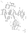
- FIG. 4 is an exploded perspective diagram illustrating a configuration of the lens module 4 in this image pickup device 2.
- FIG. 5 is a schematic diagram illustrating a detailed arrangement configurational example of each of fixed electrodes (fixed electrodes 440A, 440B, 440C, and 440D to be described later) in this lens module 4, together with each control block.
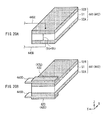
- the lens module 4 includes a support member 41, a polymer actuator element 441, a lens holding member 43, the lens 48, and a polymer actuator element 442, sequentially from the image side (the image pickup element 3 side) to the object side along an optical axis Z1 (in the normal direction of a Z-axis). It is to be noted that in FIG. 3 , illustration of the lens 48 is omitted.
- the lens module 4 further includes, as illustrated in FIG. 4 , a fixing member 42, the fixed electrodes 440A, 440B, 440C, and 440D, a presser member 46, and Hall elements 47A and 47B.
- This lens module 4 further includes, as illustrated in FIG 5 , a voltage supply section 451, a control section 452, and a storage section 453. It is to be noted that a combination of these members of the lens module 4 excluding the lens 48 corresponds to a specific example of "the driving unit” (lens driving unit) according to the embodiment of the present disclosure.
- the support member 41 is a base member (base substrate) to support the entire lens module 4, and is made of, for example, a hard resin material such as a liquid crystal polymer.
- the fixing member 42 is a member to fix one end of each of the polymer actuator elements 441 and 442, and is made of, for example, a hard resin material such as a liquid crystal polymer.
- This fixing member 42 includes three members; a lower fixing member 42D, a central (middle) fixing member 42C, and an upper fixing member 42U, which are arranged from the image side (a lower part in FIG 3 and FIG. 4 ) to the object side (an upper part).
- One end of the polymer actuator element 441 and one end of each of the fixed electrodes 440A, 440B, 440C, and 440D are disposed to be interposed between the lower fixing member 42D and the central fixing member 42C.
- one end of the polymer actuator element 442 and the other end of each of the fixed electrodes 440A, 440B, 440C, and 440D are disposed to be interposed between the central fixing member 42C and the upper fixing member 42U.
- an opening 42CO to partially hold a part of the lens holding member 43 is formed in the central fixing member 42C. This allows the part of the lens holding member 43 to move in this opening 42C0, making it possible to utilize space effectively, thereby downsizing the lens module 4.
- the lens holding member 43 is a member to hold the lens 48, and is made of, for example, a hard resin material such as a liquid crystal polymer.
- the lens holding member 43 is disposed so that a center thereof is on the optical axis Z1.
- This lens holding member 43 includes the holding section 43B shaped like a ring and holing the lens 48, and a connection section 43A supporting the holding section 43B and connecting (linking) the holding section 43B and the other end of each of the polymer actuator elements 441 and 442 to each other, at an end. Specifically, here, four corners of the connection section 43A and two pairs of projections in the polymer actuator elements 441 and 442 are connected.
- the holding section 43B is disposed between driving surfaces to be described later in the pair of polymer actuator elements 441 and 442.
- Each of the Hall elements 47A and 47B is an element used to detect a movement (displacement) of the lens holding member 43, and is, for example, a combination of a Hall element and a magnet.
- Each of the fixed electrodes 440A, 440B, 440C, and 440D is an electrode to supply a voltage from a voltage applier (the voltage supply section 451 to be described later) to electrode films (electrode films 52A and 52B) in the polymer actuator elements 441 and 442 to be described later.
- Each of the fixed electrodes 440A, 440B, 440C, and 440D is made of, for example, gold (Au), gilt metal, or the like, and here, is shaped like a letter U as illustrated in FIG. 4 and FIG. 5 .
- each of the fixed electrodes 440A, 440B, 440C, and 440D holds a top and a bottom (surfaces on both sides along the Z-axis direction) of the central fixing member 42C. This makes it possible to apply the same voltages in parallel with a small number of wirings to the pair of polymer actuator elements 441 and 442. Furthermore, in a case where the fixed electrodes 440A, 440B, 440C, and 440D are made of a gilt metallic material, it is possible to prevent deterioration of contact resistance caused by surface oxidation or the like.
- the fixed electrode 440A is disposed on one end side (the left side in the figure) along a Y-axis direction in the polymer actuator elements 441 and 442, to contact a top surface of each of them.
- the fixed electrode 440C is disposed on the other end side (the right side in the figure) along the Y-axis direction in the polymer actuator elements 441 and 442, to contact the top surface of each of them.
- the fixed electrode 440B is disposed on the one end side along the Y-axis direction in the polymer actuator elements 441 and 442, to contact an undersurface of each of them.
- the fixed electrode 440D is disposed on the other end side along the Y-axis direction in the polymer actuator elements 441 and 442, to contact the undersurface of each of them.
- driving voltages Vd for driving (operating) the polymer actuator elements 441 and 442 are supplied from the voltage supply section 451, which will be described below, each of between the fixed electrodes 440A and 440B and between the fixed electrodes 440C and 440D.
- heating voltages Vh for heating (causing generation of heat) the polymer actuator elements 441 and 442 are supplied from the voltage supply section 451, each of between the fixed electrodes 440A and 440C and between the fixed electrodes 440B and 440D.
- each of a distance between the fixed electrodes 440A and 440C and a distance between the fixed electrodes 440B and 440D to which the heating voltages Vh are applied be sufficiently longer than the thickness (the length in the Z-axis direction) of each of the polymer actuator elements 441 and 442. This is to prevent an electric field (an oblique field) from being generated along a slanting direction in a cross section of each of the polymer actuator elements 441 and 442. It is to be noted that a technique of heating the polymer actuator elements 441 and 442 using this heating voltage Vh will be described later in detail.
- the voltage supply section 451 illustrated in FIG. 5 supplies, as described above, the driving voltage Vd and the heating voltage Vh to the polymer actuator elements 441 and 442, via the fixed electrodes 440A, 440B, 440C, and 440D. Specifically, in the present embodiment in particular, as illustrated in the figure, the voltage supply section 451 supplies the driving voltage Vd along a thickness direction of each of the polymer actuator elements 441 and 442 (between the pair of electrode films 52A and 52B to be described later). On the other hand, the voltage supply section 451 supplies the heating voltage Vh along an extending direction of each of the polymer actuator elements 441 and 442 (an intra-film direction of each of the electrode films 52A and 52B to be described later). A technique of supplying the driving voltage Vd and the heating voltage Vh will be described later in detail.
- control section 452 determines whether or not to supply the heating voltage Vh, as well as the magnitude, waveform, and the like of the heating voltage Vh at the time of supplying, based on an environmental temperature (an environmental temperature T) detected directly or indirectly.
- an environmental temperature an environmental temperature T
- Such a control section 452 is configured by using, for example, a microcomputer or the like. Control operation of this control section 452 will be described later in detail.
- the storage section 453 is a memory holding beforehand data (such as characteristic data indicating a relationship between the environmental temperature T and a driving current I or a working speed v, which will be described later) used at the time of the control operation by the control section 452 described above. As such a storage section 453, various types of storage sections may be used.
- the polymer actuator elements 441 and 442 each have a driving surface orthogonal to the optical axis Z1 of the lens 48 (a driving surface on an X-Y plane), and are disposed so that the driving surfaces face each other along this optical axis Z1.
- Each of the polymer actuator elements 441 and 442 is intended to drive the lens holding member 43 (and the lens 48) along the optical axis Z1.
- Each of these polymer actuator elements 441 and 442 has, as illustrated in FIG. 6 , a sectional structure in which the pair of electrode films 52A and 52B adhere to both sides of an ionic conductive polymer compound film 51 (hereinafter merely referred to as the polymer compound film 51).
- each of the polymer actuator elements 441 and 442 has the pair of electrode films 52A and 52B, and the polymer, compound film 51 inserted between these electrode films 52A and 52B.
- the polymer actuator elements 441 and 442 and the electrode films 52A and 52B may be covered by an insulating protective film made of a material having high elasticity (for example, polyurethane) in the periphery thereof.
- the electrode film 52A is electrically connected to the fixed electrodes 440B and 440D on the lower fixing member 42D side, and the electrode film 52B is electrically connected to the fixed electrodes 440A and 440C on the central fixing member 42C side.
- the electrode film 52A is electrically connected to the fixed electrodes 440B and 440D on the central fixing member 42C side, and the electrode film 52B is electrically connected to the fixed electrodes 440A and 440C on the upper fixing member 42U side.
- the presser member 46 flat spring
- the polymer compound film 51 is configured to be curved by a predetermined potential difference occurring between the electrode films 52A and 52B.
- This polymer compound film 51 is impregnated with an ionic substance.
- the "ionic substance” here means a substance including cations and/or anions and a polar solvent, or a substance including liquid cations and/or anions.
- a polar solvent is solvated in cations and/or anions
- there is an ionic liquid there is a substance in which a polar solvent is solvated in cations and/or anions.
- the polymer compound film 51 there is, for example, an ion exchange resin in which a fluorocarbon resin or a hydrocarbon system is a skeleton.
- an ion exchange resin in which a fluorocarbon resin or a hydrocarbon system is a skeleton.
- the ion exchange resin it is preferable to use a cation exchange resin when a cationic substance is impregnated, and use an anion exchange resin when an anionic substance is impregnated.
- the cation exchange resin there is, for example, a resin into which an acidic group such as a sulfonate group or a carboxyl group is introduced.
- the cation exchange resin is a polyethylene having an acidic group, a polystyrene having an acidic group, a fluorocarbon resin having an acid group, or the like.
- a fluorocarbon resin having a sulfonate group or a carboxylic acid group is preferable as the cation exchange resin, and there is, for example, Nafion (made by E. I. du Pont de Nemours and Company).
- the cationic substance impregnated in the polymer compound film 51 be a substance including metal ions and water, a substance including organic cations and water, or an ionic liquid.
- the metal ion there is, for example, light metal ion such as sodium ion (Na + ), potassium ion (K + ), lithium ion (Li + ), or magnesium ion (Mg 2+ ).
- the organic cation there is, for example, alkylammonium ion. These cations exist as a hydrate in the polymer compound film 51. Therefore, in a case where the polymer compound film 51 is impregnated with the cationic substance including cations and water, it is desirable to seal the whole in order to suppress volatilization of the water, in the polymer actuator elements 441 and 442.
- the ionic liquid is also called ambient temperature molten salt, and includes cations and anions having low combustion and volatility.
- the ionic liquid there is, for example, an imidazolium ring system compound, a pyridinium ring system compound, or an aliphatic compound.
- the cationic substance be the ionic liquid. This is because the volatility is low, and the polymer actuator elements 441 and 442 work well even in a high-temperature atmosphere or in a vacuum.
- each of the electrode films 52A and 52B facing each other across the polymer compound film 51 interposed therebetween includes one or more than one kind of conductive material. It is preferable that each of the electrode films 52A and 52B be a film in which particles of a conductive material powder are bound by an ionic conductive polymer. This is because flexibility of the electrode films 52A and 52B increases.
- a carbon powder is preferable as the conductive material powder. This is because the conductivity is high, and the specific surface area is large and thus, a larger deformation is achieved.
- Ketjen black is preferable.
- the ionic conductive polymer the same material as that of the polymer compound film 51 is desirable.
- the electrode films 52A and 52B are formed as follows, for example. A coating in which a conductive material powder and a conductive polymer are dispersed in a dispersion medium is applied to each of both sides of the polymer compound film 51, and then dried. A film-shaped substance including a conductive material powder and an ionic conductive polymer may be pressure-bonded to each of both sides of the polymer compound film 51.
- the electrode films 52A and 52B may each have a multilayer structure, and in that case, it is desirable that each of the electrode films 52A and 52B have such a structure that a layer in which particles of a conductive material powder are bound by an ionic conductive polymer and a metal layer are laminated sequentially from the polymer compound film 51 side. This is because an electric potential becomes closer to a further uniform value in an in-plane direction of the electrode films 52A and 52B, and superior deformability is obtained.
- a material of the metal layer there is a noble metal such as gold or platinum.
- the thickness of the metal layer is arbitrary, but is preferably a continuous film so that the electric potential becomes uniform in the electrode films 52A and 52B.
- As a method of forming the metal layer there is plating, deposition, sputtering, or the like.
- the size (width and length) of the polymer compound film 51 may be, for example, freely set according to the size and weight of the lens holding member 43, or a desirable displacement of the polymer compound film 51.
- the displacement of the polymer compound film 51 is set according to a desired movement along the optical axis Z1 of the lens holding member 43.
- FIGs. 8A and 8B each schematically illustrate the operation of the polymer actuator elements 441 and 442, using a cross-sectional diagram.
- the cationic substance disperses approximately uniformly in the polymer compound film 51 and thus, the polymer actuator elements 441 and 442 in a state of no voltage application become flat without curving ( FIG. 8A ).
- the polymer actuator elements 441 and 442 exhibit the following behavior.
- the predetermined driving voltage Vd is applied between the electrode films 52A and 52B so that the electrode film 52A is at a negative potential whereas the electrode film 52B is at a positive potential
- the cations in a state of being solvated in the polar solvent move to the electrode film 52A side.
- the anions hardly move in the polymer compound film 51 and thus, in the polymer compound film 51, the electrode film 52A side swells, while the electrode film 52B side shrinks.
- the polymer actuator elements 441 and 442 curve toward the electrode film 52B side as a whole, as illustrated in FIG. 8B .
- the state of no voltage application is established by eliminating the potential difference between the electrode films 52A and 52B (the application of the driving voltage Vd is stopped)
- the cationic substance the cations and polar solvent
- the cations in the state of being solvated in the polar solvent move to the electrode film 52B side.
- the electrode film 52A side shrinks while the electrode film 52B side swells and thus, as a whole, the polymer actuator elements 441 and 442 curve toward the electrode film 52A side.
- the polymer actuator elements 441 and 442 become flat as illustrated in FIG. 8A .
- the polymer actuator elements 441 and 442 exhibit the following behavior.
- the predetermined driving voltage Vd is applied between the electrode films 52A and 52B so that the electrode film 52B is at a positive potential, whereas the electrode film 52A is at a negative potential, the cations of the ionic liquid move to the electrode film 52A side, and the anions hardly move in the polymer compound film 51 which is a cation-exchanger membrane. For this reason, in the polymer compound film 51, the electrode film 52A side swells, while the electrode film 52B side shrinks. As a result, the polymer actuator elements 441 and 442 curve toward the electrode film 52B side as a whole, as illustrated in FIG. 8B .
- the cations localized to the electrode film 52A side in the polymer compound film 51 diffuse, and return to the state illustrated in FIG. 8A .
- the predetermined driving voltage Vd is applied between the electrode films 52A and 52B so that the electrode film 52A shifts to a positive potential and the electrode film 52B shifts to a negative potential from the state of no voltage application illustrated in FIG. 8A , the cations of the ionic liquid move to the electrode film 52B side.
- the electrode film 52A side shrinks, whereas the electrode film 52B side swells and thus, as a whole, the polymer actuator elements 441 and 442 curve toward the electrode film 52A side.
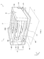
- FIGs. 9A and 9B each illustrate the operation of the lens module 4 in the image pickup device 2 in a perspective diagram.
- FIG. 9A illustrates a state before the operation
- FIG. 9B illustrates a state after the operation.
- the lens 48 becomes movable along the optical axis Z1, by driving the lens holding member 43 through use of the pair of polymer actuator elements 441 and 442.
- the lens 48 is driven along the optical axis Z1 by the driving unit (lens driving unit) employing the polymer actuator elements 441 and 442.
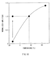
- the characteristic of the element declines (deteriorates) in a low temperature environment (here, for example, around -30°C), compared to a room temperature environment (here, for example, around 25°C).
- a low temperature environment here, for example, around -30°C
- a room temperature environment here, for example, around 25°C.
- the displacement of the polymer actuator elements 441 and 442 illustrated in the figure declines, and the working speed decreases.
- ion mobility in the polymer compound film 51 (ion exchange resin film) described above decreases in the low temperature environment, compared to the room temperature environment.
- the voltage supply section 451 supplies the polymer actuator elements 441 and 442 with the heating voltage Vh in addition to the driving voltage Vd, via the fixed electrodes 440A, 440B, 440C, and 440D.
- This allows the temperature of the element to rise through heat generated by the polymer actuator elements 441 and 442 themselves (by using the elements themselves as a heat source), without providing the above-mentioned dedicated heat source outside the element separately.
- it is possible to improve the characteristics (the displacement or the working speed) of the polymer actuator elements 441 and 442 in the low temperature environment (see, for example, an arrow in FIG. 10 ). In other words, the characteristics equal or superior to those in the room temperature environment may be obtained even in the low temperature environment.
- the voltage supply section 451 of the present embodiment supplies the driving voltage Vd (here, along a Z-axis direction) between the pair of electrode films 52A and 52B in each of the polymer actuator elements 441 and 442.
- the voltage supply section 451 supplies the driving voltage Vd to each of between the fixed electrodes 440A and 440B and between the fixed electrodes 440C and 440D.
- the voltage supply section 451 of the present embodiment supplies the heating voltage Vh (here, along the Y-axis direction) in the intra-film direction of each of the electrode films 52A and 52B in each of the polymer actuator elements 441 and 442.
- the voltage supply section 451 supplies the heating voltage Vh to each of between the fixed electrodes 440A and 440C and between the fixed electrodes 440B and 440D.
- the voltage supply section 451 selectively supplies the heating voltage Vh to a region (a region on a root side) of the fixing member 42 side (a fixed side) in the polymer actuator elements 441 and 442.
- the voltage supply section 451 supplies the heating voltage Vh along a width direction (here, a Y-axis direction) in the region on the root side of the polymer actuator elements 441 and 442.
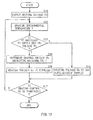
- FIG. 12 is a flowchart illustrating an example of the technique of heating the polymer actuator elements 441 and 442 according to the present embodiment.
- the voltage supply section 451 supplies the driving voltage Vd to the polymer actuator elements 441 and 442, thereby causing these polymer actuator elements 441 and 442 to operate (transform) (step S11).
- an environmental temperature T around the polymer actuator elements 441 and 442 is measured (detected) directly or indirectly by a measuring section (a detecting section) not illustrated (step S12).
- the environmental temperature T is detected directly by, for example, an external temperature sensor or the like such as a thermocouple.
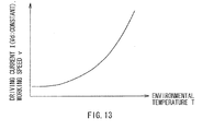
- the environmental temperature T is detected indirectly based on a measured driving current I or a working speed v, by using characteristic data indicating the relationship between the measured driving current I flowing in the element (when the driving voltage Vd is constant) and the environmental temperature T, characteristic data indicating the relationship between the working speed v of the element and the environmental temperature T, or the like (for example, see FIG. 13 ).
- the measurement of the driving current I may be performed using, for example, an ammeter not illustrated, and the measurement of the working speed v may be performed using, for example, a result of measurement in the Hall elements 47A and 47B.
- the characteristic data indicating the relationship between the environmental temperature T and the driving current I or the working speed v described above may be held beforehand in, for example, the storage section 453.
- the control section 452 first determines (decides) whether or not to supply (whether it is necessary to supply) the heating voltage Vh (step S13). Specifically, for example, when the detected environmental temperature T is lower than a predetermined threshold temperature Tth (the environment is the low temperature environment), the control section 452 determines that it is necessary to supply the heating voltage Vh. On the other hand, when the detected environmental temperature T is higher than the threshold temperature Tth mentioned above (the environment is not the low temperature environment), the control section 452 determines that it is not necessary to supply the heating voltage Vh.
- step S13: N When the control section 452 determines (decides) that it is not necessary to supply the heating voltage Vh (step S13: N), the voltage supply section 451 does not supply the heating voltage Vh (or stops supplying, or lowers the value of the heating voltage Vh) (step S 14). After that, the flow proceeds to step S 17 to be described later.
- control section 452 determines (decides) that it is necessary to supply the heating voltage Vh (step S13: Y)
- the control section 452 subsequently determines (decides) the magnitude, waveform, and the like of the heating voltage Vh to be supplied, based on the above-described environmental temperature T (step S15).
- the control section 452 determines the magnitude (voltage value) of the heating voltage Vh, whether the heating voltage Vh is a direct current (DC) voltage or an alternating current (AC) voltage, the frequency in the case of the AC voltage, and the like.
- FIG. 14A a situation schematically illustrated, for example, in FIG. 14A will be considered.
- driving voltages Vd1 and Vd2 at both ends of each of the polymer actuator elements 441 and 442 along the Y-axis direction are supplied to become equal to each other.
- FIGs. 14B and 14C there are two combinations illustrated in FIGs. 14B and 14C as described below.
- each of Vd, Vd1, and Vd2 represents an arbitrary DC or AC driving voltage ( ⁇ 0 volt)
- each of Vh, Vh1 and Vh2 represents an arbitrary DC or AC heating voltage ( ⁇ 0 volt)
- the direction of each arrow indicates the direction of a voltage drop (a positive potential difference).
- the driving voltage Vd and the heating voltage Vh at this time are arbitrary voltages independent of each other (the respective voltage values and phases may be different). In addition, it is possible to determine the driving voltage Vd and the heating voltage Vh independently, by adjusting the voltages to be supplied to the fixed electrodes 440A, 440B, 440C, and 440D.
- Vd ⁇ 1 Vh ⁇ 1 + Vd ⁇ 2 - Vh ⁇ 2
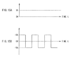
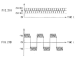
- heating voltage Vh it is possible to use, for example, a DC voltage as illustrated in FIG. 15A , or an AC voltage as illustrated in FIG. 15B , but use of the AC voltage is desirable. This is to prevent the localization of ions from occurring along the film thickness direction in the polymer compound film 51 (to prevent undesirable deformation from taking place).
- the voltage supply section 451 supplies the heating voltage Vh determined in this way by the control section 452 to the polymer actuator elements 441 and 442 (step S 16). Subsequently, the control section 452 determines whether or not to terminate the entire heating control illustrated in FIG. 12 , in accordance with, for example, a command from a user, or the like (step S17). When it is determined that the heating control is not to be terminated (is to be continued) (step S17: N), the flow returns to step S12 described above, and when it is determined that the heating control is to be terminated (step S17: Y), the entire control ends.
- FIGs. 16A and 16B illustrate an effect of applying the heating voltage Vh according to an example of the present embodiment.
- FIG. 16A illustrates a relationship between time (voltage application time) and the displacement of the polymer actuator elements 441 and 442, and
- FIG. 16B illustrates a relationship between the heating voltage Vh and the amplitude during the operation of the polymer actuator elements 441 and 442.
- the environmental temperature T -20°C
- the driving voltage Vd 1 volt ( ⁇ 1 volt)
- a frequency f of the driving voltage Vd 1 Hz.
- arrows in FIG. 16A each indicate the timing when the supply of the driving voltage Vd is started.
- the driving voltage Vd and the heating voltage Vh are supplied to the polymer actuator elements 441 and 442 and thus, it is possible to increase the temperature of the elements by the heat generation of the polymer actuator elements 441 and 442 themselves, and it is possible to improve the displacement, the working speed, and the like of the elements in the low temperature environment, without providing an external dedicated heat source separately. Therefore, it is possible to improve the characteristics in the low temperature environment, while reducing the size (the weight).
- the heating voltage Vh is supplied selectively to the region (the region on the root side) on the fixing member 42 side (the fixed side) in the polymer actuator elements 441 and 442 and thus, it is possible to simplify the wiring structure to supply the heating voltage Vh, compared to the technique of the modification 2 that will be described later.
- the root region where the displacement is relatively large in the polymer actuator elements 441 and 442 is selectively heated and thus, it is possible to heat the elements efficiently, compared to the technique of the modification 2.
- FIGs. 17A to 17C each illustrate a configurational example of polymer actuator elements 441 and 442 and fixed electrodes (here, fixed electrodes 440A and 440C are taken as examples) according to the modification 1, in a schematic diagram.
- a heating voltage Vh is supplied (from a fixed side along a movable side) to the entire surface in each of electrode films 52A and 52B of each of the polymer actuator elements 441 and 442, while the configuration of the fixed electrodes in the embodiment described above is basically used.
- the pair of fixed electrodes 440A and 440C are provided on the fixing member 42 side (fixed side) on the electrode film 52B of each of the polymer actuator elements 441 and 442.
- a notch 40C (first notch section) is formed by cutting the whole elements (each film) from an end on the fixed side to the opposite side (to the normal direction of an X-axis), in a region between these fixed electrodes 440A and 440C.
- the pair of fixed electrodes 440A and 440C are provided on the fixing member 42 side (fixed side) on the electrode film 52B of each of the polymer actuator elements 441 and 442.
- a notch 40C (second notch section) is formed by selectively cutting the polymer actuator elements 441 and 442, from the end on the fixed side to the opposite side (to the normal direction of the X-axis), in the region between these fixed electrodes 440A and 440C.
- the pair of fixed electrodes 440A and 440C are provided on the fixing member 42 side (fixed side) on the electrode film 52B of each of the polymer actuator elements 441 and 442.
- a wire for example, a metal wire
- 40W that establishes an electrical connection between the pair of fixed electrodes 440A and 440C from the fixed side via the opposite side (the movable side).
- heating voltage Vh to the entire surface in each of the electrode films 52A and 52B of each of the polymer actuator elements 441 and 442 (from the fixed side along the movable side), while using a configuration basically similar to that of the fixed electrodes in the embodiment described above.
- heating efficiency may be improved and a structure in which the temperature is increased more easily is provided, compared to the examples illustrated in FIGs. 17A and 17B , when the same heating voltages Vh are used.
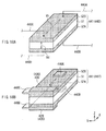
- FIGs. 18A and 18B each illustrate the technique of applying the driving voltage Vd and the heating voltage Vh according to the modification 2, in a schematic perspective diagram.
- the heating voltage Vh is supplied to the entire surface in each of electrode films 52A and 52B of each of polymer actuator elements 441 and 442 (from a fixed side along a movable side), while changing the configuration of the fixed electrodes in the embodiment and the modification 1 described above.
- the voltage supply section 451 of the present modification first supplies the driving voltage Vd between the pair of electrode films 52A and 52B in each of the polymer actuator elements 441 and 442, as in the embodiment described above.
- the voltage supply section 451 supplies the driving voltage Vd to each of between fixed electrodes 440A and 440B and between fixed electrodes 440C and 440D.
- the voltage supply section 451 supplies the heating voltage Vh in an intra-film direction of each of the electrode films 52A and 52B in each of the polymer actuator elements 441 and 442.
- the voltage supply section 451 supplies the heating voltage Vh to each of between the fixed electrodes 440A and 440C and between the fixed electrodes 440B and 440D.
- the voltage supply section 451 of the present modification supplies the heating voltage Vh from a region on the fixing member 42 side (a fixed side, or a root side) along the opposite side (a movable section side) in the polymer actuator elements 441 and 442 (here, along an X-axis direction).
- the voltage supply section 451 supplies the heating voltage Vh along a direction from the root side to the tip (in a length direction) of the polymer actuator elements 441 and 442.
- the present modification only the fixed electrodes 440C and 440D are provided on a fixed section side, and the fixed electrodes 440A and 440B are provided on the movable section side (the tip side).
- FIGs. 19A and 19B illustrate an effect of applying the heating voltage Vh according to an example of the present modification.
- FIG. 19A illustrates a relationship between time (voltage application time) and the displacement of the polymer actuator elements 441 and 442, and
- FIG. 19B illustrates a relationship between the heating voltage Vh and the amplitude during the operation of the polymer actuator elements 441 and 442.
- the environmental temperature T -20°C
- the driving voltage Vd 2 volts ( ⁇ 2 volts)
- a frequency f of the driving voltage Vd 1 Hz.
- an arrow in FIG. 19A indicates the timing when the supply of the driving voltage Vd is started.
- FIGs. 20A and 20B each illustrate a technique of applying a driving voltage Vd and a heating voltage Vh according to the modification 3, in a schematic perspective diagram.
- the heating voltage Vh is applied between electrode films 52A and 52B of each of polymer actuator elements 441 and 442.
- a voltage supply section 451 of the present modification first supplies a driving voltage Vd between the pair of electrode films 52A and 52B in each of the polymer actuator elements 441 and 442, as in the embodiment and the like described above. Specifically, in the present modification, the voltage supply section 451 supplies the driving voltage Vd between fixed electrodes 440C and 440D.
- the voltage supply section 451 of the present modification also supplies the heating voltage Vh, in addition to the driving voltage Vd, between the pair of electrode films 52A and 52B in each of the polymer actuator elements 441 and 442.
- the voltage supply section 451 also supplies the heating voltage Vh between the fixed electrodes 440C and 440D. In this way, in the present modification, both the driving voltage Vd and the heating voltage Vh are supplied between the pair of electrode films 52A and 52B in each of the polymer actuator elements 441 and 442.
- the voltage supply section 451 supplies the heating voltage Vh and the driving voltage Vd by superimposing the heating voltage Vh of a high-frequency AC voltage (for example, around 1 kHz) on the driving voltage Vd of a DC voltage or an AC voltage.
- a high-frequency AC voltage for example, around 1 kHz
- the heating voltage Vh of the high frequency on a level that does not allow the polymer actuator elements 441 and 442 to follow (deform) is superimposed on the driving voltage Vd and thus, it is possible to obtain effects similar to those in the embodiment and the like described above.
- the present modification in particular, as illustrated in FIGs.
- the technique of supplying the driving voltage Vd and the heating voltage Vh and their waveforms and the like are not limited to those described in the embodiment and the like, and other techniques and waveforms may be employed.
- a part supplying the driving voltage Vd and a part supplying the heating voltage Vh may be provided separately, or the parts supplying these two types of voltage may be commonized (unified) and provided.
- the part supplying the driving voltage Vd and the part supplying the heating voltage Vh are provided separately, it is desirable to provide a driving electrode and a heating electrode separately. This is because if these electrodes are commonized, independent voltages may not be supplied.
- the polymer actuator elements may not be a pair, and one or three or more polymer actuator elements may be provided.
- the shape of the polymer actuator element is not limited to that in each of the embodiment and the like and also, the layered structure thereof is not limited to that described in each of the embodiment and the like and may be modified as appropriate.
- the shape, material, and the like of each member in the lens module (driving unit) are not limited as well to those described in the embodiment and the like.
- the embodiment and the like have been described by taking the lens driving unit that drives the lens along the optical axis as an example of the driving unit according to the embodiment of the present disclosure, but the driving unit is not limited to this case.
- the driving unit according to the embodiment of the present disclosure is applicable to, for example, a driving unit that drives a diaphragm or the like (see Japanese Patent Application Publication No. 2008-259381 and the like), other than such a lens driving unit.
- the driving unit, the lens module, and the image pickup device according to the embodiment of the present disclosure are applicable to various kinds of electronic device, other than the portable telephone described in the above embodiment and the like.
Landscapes
- Physics & Mathematics (AREA)
- Engineering & Computer Science (AREA)
- General Physics & Mathematics (AREA)
- Optics & Photonics (AREA)
- Chemical & Material Sciences (AREA)
- General Engineering & Computer Science (AREA)
- Combustion & Propulsion (AREA)
- Spectroscopy & Molecular Physics (AREA)
- Mechanical Engineering (AREA)
- Analytical Chemistry (AREA)
- Multimedia (AREA)
- Signal Processing (AREA)
- Lens Barrels (AREA)
- Studio Devices (AREA)
- Camera Bodies And Camera Details Or Accessories (AREA)
Applications Claiming Priority (1)
| Application Number | Priority Date | Filing Date | Title |
|---|---|---|---|
| JP2010181716A JP5824791B2 (ja) | 2010-08-16 | 2010-08-16 | 駆動装置、レンズモジュールおよび撮像装置 |
Publications (1)
| Publication Number | Publication Date |
|---|---|
| EP2420879A1 true EP2420879A1 (en) | 2012-02-22 |
Family
ID=44674219
Family Applications (1)
| Application Number | Title | Priority Date | Filing Date |
|---|---|---|---|
| EP20110176581 Withdrawn EP2420879A1 (en) | 2010-08-16 | 2011-08-04 | Driving unit, lens module, and image pickup device |
Country Status (5)
| Country | Link |
|---|---|
| US (1) | US9127652B2 (enExample) |
| EP (1) | EP2420879A1 (enExample) |
| JP (1) | JP5824791B2 (enExample) |
| KR (1) | KR20120016584A (enExample) |
| CN (1) | CN102375204A (enExample) |
Cited By (1)
| Publication number | Priority date | Publication date | Assignee | Title |
|---|---|---|---|---|
| WO2014075681A1 (en) * | 2012-11-14 | 2014-05-22 | Danfoss Polypower A/S | A polymer transducer |
Families Citing this family (10)
| Publication number | Priority date | Publication date | Assignee | Title |
|---|---|---|---|---|
| DE102016004673B4 (de) * | 2016-04-18 | 2020-01-02 | Kastriot Merlaku | Antriebssystem für eine frei drehbare Kamera |
| WO2017188798A1 (ko) | 2016-04-29 | 2017-11-02 | 엘지이노텍(주) | 액체 렌즈를 포함하는 카메라 모듈, 이를 포함하는 광학 기기, 및 액체 렌즈를 포함하는 카메라 모듈의 제조 방법 |
| JP7043171B2 (ja) * | 2017-01-25 | 2022-03-29 | 株式会社ジャパンディスプレイ | 表示装置 |
| KR102362731B1 (ko) * | 2017-04-11 | 2022-02-15 | 엘지이노텍 주식회사 | 액체 렌즈 제어 회로 |
| EP3451397A1 (en) * | 2017-08-28 | 2019-03-06 | Koninklijke Philips N.V. | Actuator device and method |
| US10656373B1 (en) | 2017-11-01 | 2020-05-19 | Facebook Technologies, Llc | Apparatuses, systems, and methods for a multistable lens actuator providing multiple stabilized discrete positions |
| KR101908658B1 (ko) | 2017-11-02 | 2018-12-10 | 엘지이노텍 주식회사 | 액체 렌즈를 포함하는 카메라 모듈 및 광학 기기 |
| US10386546B2 (en) | 2017-11-02 | 2019-08-20 | Lg Innotek Co., Ltd. | Camera module and optical device including liquid lens |
| KR102486424B1 (ko) * | 2018-01-23 | 2023-01-09 | 엘지이노텍 주식회사 | 카메라 모듈 |
| US11565208B2 (en) | 2021-06-22 | 2023-01-31 | Caterpillar Inc. | Air filter element with pre-cleaning tubes |
Citations (6)
| Publication number | Priority date | Publication date | Assignee | Title |
|---|---|---|---|---|
| JP2006172635A (ja) | 2004-12-17 | 2006-06-29 | Eamex Co | 高分子アクチュエータを用いた光ピックアップ装置の対物レンズ駆動体 |
| JP2006293006A (ja) | 2005-04-11 | 2006-10-26 | Olympus Corp | 光学装置およびデジタルカメラ |
| JP2008259381A (ja) | 2007-04-09 | 2008-10-23 | Eamex Co | アクチュエータ体および絞り機構 |
| US20100033835A1 (en) * | 2005-03-21 | 2010-02-11 | Artificial Muscle, Inc. | Optical lens displacement systems |
| US20100171393A1 (en) * | 2008-12-10 | 2010-07-08 | The Regents Of The University Of California | Bistable electroactive polymers |
| JP2010181716A (ja) | 2009-02-06 | 2010-08-19 | Olympus Corp | 観察装置 |
Family Cites Families (10)
| Publication number | Priority date | Publication date | Assignee | Title |
|---|---|---|---|---|
| JP2005278133A (ja) * | 2003-07-03 | 2005-10-06 | Fuji Photo Film Co Ltd | 固体撮像装置および光学機器 |
| KR100962308B1 (ko) | 2003-07-22 | 2010-06-11 | 삼성테크윈 주식회사 | Ccd 카메라장치 |
| JP4732798B2 (ja) * | 2005-05-19 | 2011-07-27 | 株式会社日立製作所 | アクチュエーターおよびアクチュエーターモジュール |
| US9041851B2 (en) * | 2005-11-15 | 2015-05-26 | The Trustees Of Princeton University | Organic electronic detectors and methods of fabrication |
| JP2007140169A (ja) | 2005-11-18 | 2007-06-07 | Fujifilm Corp | 手ぶれ補正ユニットおよび撮影装置 |
| US7813047B2 (en) * | 2006-12-15 | 2010-10-12 | Hand Held Products, Inc. | Apparatus and method comprising deformable lens element |
| JP2008216074A (ja) * | 2007-03-05 | 2008-09-18 | Yaskawa Electric Corp | 高分子アクチュエータの伸縮量センシング方法および伸縮量センシング装置 |
| WO2009076477A1 (en) * | 2007-12-10 | 2009-06-18 | Artificial Muscle, Inc. | Optical lens image stabilization systems |
| JP4645919B2 (ja) | 2008-09-10 | 2011-03-09 | ソニー株式会社 | レンズ駆動装置及び撮像装置 |
| JP5466757B2 (ja) * | 2010-03-16 | 2014-04-09 | アルプス電気株式会社 | 高分子アクチュエータ素子を用いた駆動装置 |
-
2010
- 2010-08-16 JP JP2010181716A patent/JP5824791B2/ja not_active Expired - Fee Related
-
2011
- 2011-08-04 EP EP20110176581 patent/EP2420879A1/en not_active Withdrawn
- 2011-08-08 KR KR20110078668A patent/KR20120016584A/ko not_active Withdrawn
- 2011-08-09 US US13/205,941 patent/US9127652B2/en not_active Expired - Fee Related
- 2011-08-09 CN CN2011102294909A patent/CN102375204A/zh active Pending
Patent Citations (6)
| Publication number | Priority date | Publication date | Assignee | Title |
|---|---|---|---|---|
| JP2006172635A (ja) | 2004-12-17 | 2006-06-29 | Eamex Co | 高分子アクチュエータを用いた光ピックアップ装置の対物レンズ駆動体 |
| US20100033835A1 (en) * | 2005-03-21 | 2010-02-11 | Artificial Muscle, Inc. | Optical lens displacement systems |
| JP2006293006A (ja) | 2005-04-11 | 2006-10-26 | Olympus Corp | 光学装置およびデジタルカメラ |
| JP2008259381A (ja) | 2007-04-09 | 2008-10-23 | Eamex Co | アクチュエータ体および絞り機構 |
| US20100171393A1 (en) * | 2008-12-10 | 2010-07-08 | The Regents Of The University Of California | Bistable electroactive polymers |
| JP2010181716A (ja) | 2009-02-06 | 2010-08-19 | Olympus Corp | 観察装置 |
Cited By (1)
| Publication number | Priority date | Publication date | Assignee | Title |
|---|---|---|---|---|
| WO2014075681A1 (en) * | 2012-11-14 | 2014-05-22 | Danfoss Polypower A/S | A polymer transducer |
Also Published As
| Publication number | Publication date |
|---|---|
| CN102375204A (zh) | 2012-03-14 |
| JP5824791B2 (ja) | 2015-12-02 |
| US9127652B2 (en) | 2015-09-08 |
| JP2012042560A (ja) | 2012-03-01 |
| US20120038815A1 (en) | 2012-02-16 |
| KR20120016584A (ko) | 2012-02-24 |
Similar Documents
| Publication | Publication Date | Title |
|---|---|---|
| EP2420879A1 (en) | Driving unit, lens module, and image pickup device | |
| JP4501085B2 (ja) | 光学素子モジュール及び撮像装置 | |
| JP5152483B2 (ja) | 撮像装置 | |
| US9397360B2 (en) | Drive unit, lens module, image pickup unit, fuel cell, and ion exchange resin | |
| CN102543440A (zh) | 可变电容装置、天线模块及通信装置 | |
| US8587886B2 (en) | Lens drive device, lens module, and image pickup device | |
| US9706087B2 (en) | Polymer element, electronic device, camera module, and imaging apparatus | |
| KR101956404B1 (ko) | 구동 장치, 렌즈 모듈 및 촬상 장치 | |
| US8830385B2 (en) | Drive unit, lens module, and image pickup unit | |
| JP5765020B2 (ja) | レンズモジュール、撮像装置、および電子機器 | |
| JPWO2012063701A1 (ja) | 駆動装置およびその製造方法、レンズモジュールならびに撮像装置 | |
| TW200921476A (en) | Display device | |
| CN105934467A (zh) | 离子交换膜、聚合物元件、电子设备、照相机模块及摄像装置 | |
| CN104122642A (zh) | 聚合物器件、其制造方法、摄像机模块以及成像单元 | |
| CN113810561A (zh) | 驱动装置、摄像头模组及电子设备 | |
| JP2008242274A (ja) | フレキシブルプリント基板、液晶光学装置および液晶光学装置の製造方法 |
Legal Events
| Date | Code | Title | Description |
|---|---|---|---|
| 17P | Request for examination filed |
Effective date: 20110823 |
|
| AK | Designated contracting states |
Kind code of ref document: A1 Designated state(s): AL AT BE BG CH CY CZ DE DK EE ES FI FR GB GR HR HU IE IS IT LI LT LU LV MC MK MT NL NO PL PT RO RS SE SI SK SM TR |
|
| AX | Request for extension of the european patent |
Extension state: BA ME |
|
| PUAI | Public reference made under article 153(3) epc to a published international application that has entered the european phase |
Free format text: ORIGINAL CODE: 0009012 |
|
| STAA | Information on the status of an ep patent application or granted ep patent |
Free format text: STATUS: THE APPLICATION HAS BEEN WITHDRAWN |
|
| 18W | Application withdrawn |
Effective date: 20150217 |