EP2420344B1 - Procédé et dispositif de découpe d'un contour dans une bande de tôle - Google Patents
Procédé et dispositif de découpe d'un contour dans une bande de tôle Download PDFInfo
- Publication number
- EP2420344B1 EP2420344B1 EP11176675.4A EP11176675A EP2420344B1 EP 2420344 B1 EP2420344 B1 EP 2420344B1 EP 11176675 A EP11176675 A EP 11176675A EP 2420344 B1 EP2420344 B1 EP 2420344B1
- Authority
- EP
- European Patent Office
- Prior art keywords
- laser cutting
- transport
- breakthrough
- width
- cutting device
- Prior art date
- Legal status (The legal status is an assumption and is not a legal conclusion. Google has not performed a legal analysis and makes no representation as to the accuracy of the status listed.)
- Active
Links
- 239000002184 metal Substances 0.000 title claims description 79
- 238000000034 method Methods 0.000 title claims description 14
- 238000003698 laser cutting Methods 0.000 claims description 140
- 238000012545 processing Methods 0.000 claims description 51
- 238000004519 manufacturing process Methods 0.000 claims description 17
- 238000011144 upstream manufacturing Methods 0.000 claims description 16
- 238000009434 installation Methods 0.000 claims 2
- 230000000717 retained effect Effects 0.000 claims 1
- 238000005520 cutting process Methods 0.000 description 3
- 230000001133 acceleration Effects 0.000 description 2
- 230000008859 change Effects 0.000 description 2
- 230000008569 process Effects 0.000 description 2
- 230000009471 action Effects 0.000 description 1
- 238000010276 construction Methods 0.000 description 1
- 230000007423 decrease Effects 0.000 description 1
- 230000001419 dependent effect Effects 0.000 description 1
- 230000000694 effects Effects 0.000 description 1
- 238000003780 insertion Methods 0.000 description 1
- 230000037431 insertion Effects 0.000 description 1
- 230000003993 interaction Effects 0.000 description 1
- 230000000149 penetrating effect Effects 0.000 description 1
- 238000012805 post-processing Methods 0.000 description 1
- 238000004886 process control Methods 0.000 description 1
- 230000001681 protective effect Effects 0.000 description 1
- 238000000926 separation method Methods 0.000 description 1
- 238000009966 trimming Methods 0.000 description 1
Images
Classifications
-
- B—PERFORMING OPERATIONS; TRANSPORTING
- B23—MACHINE TOOLS; METAL-WORKING NOT OTHERWISE PROVIDED FOR
- B23K—SOLDERING OR UNSOLDERING; WELDING; CLADDING OR PLATING BY SOLDERING OR WELDING; CUTTING BY APPLYING HEAT LOCALLY, e.g. FLAME CUTTING; WORKING BY LASER BEAM
- B23K26/00—Working by laser beam, e.g. welding, cutting or boring
- B23K26/08—Devices involving relative movement between laser beam and workpiece
- B23K26/083—Devices involving movement of the workpiece in at least one axial direction
- B23K26/0838—Devices involving movement of the workpiece in at least one axial direction by using an endless conveyor belt
- B23K26/0846—Devices involving movement of the workpiece in at least one axial direction by using an endless conveyor belt for moving elongated workpieces longitudinally, e.g. wire or strip material
-
- B—PERFORMING OPERATIONS; TRANSPORTING
- B23—MACHINE TOOLS; METAL-WORKING NOT OTHERWISE PROVIDED FOR
- B23K—SOLDERING OR UNSOLDERING; WELDING; CLADDING OR PLATING BY SOLDERING OR WELDING; CUTTING BY APPLYING HEAT LOCALLY, e.g. FLAME CUTTING; WORKING BY LASER BEAM
- B23K26/00—Working by laser beam, e.g. welding, cutting or boring
- B23K26/08—Devices involving relative movement between laser beam and workpiece
- B23K26/0869—Devices involving movement of the laser head in at least one axial direction
- B23K26/0876—Devices involving movement of the laser head in at least one axial direction in at least two axial directions
-
- B—PERFORMING OPERATIONS; TRANSPORTING
- B23—MACHINE TOOLS; METAL-WORKING NOT OTHERWISE PROVIDED FOR
- B23K—SOLDERING OR UNSOLDERING; WELDING; CLADDING OR PLATING BY SOLDERING OR WELDING; CUTTING BY APPLYING HEAT LOCALLY, e.g. FLAME CUTTING; WORKING BY LASER BEAM
- B23K26/00—Working by laser beam, e.g. welding, cutting or boring
- B23K26/36—Removing material
- B23K26/38—Removing material by boring or cutting
-
- B—PERFORMING OPERATIONS; TRANSPORTING
- B23—MACHINE TOOLS; METAL-WORKING NOT OTHERWISE PROVIDED FOR
- B23K—SOLDERING OR UNSOLDERING; WELDING; CLADDING OR PLATING BY SOLDERING OR WELDING; CUTTING BY APPLYING HEAT LOCALLY, e.g. FLAME CUTTING; WORKING BY LASER BEAM
- B23K37/00—Auxiliary devices or processes, not specially adapted to a procedure covered by only one of the preceding main groups
- B23K37/02—Carriages for supporting the welding or cutting element
- B23K37/0211—Carriages for supporting the welding or cutting element travelling on a guide member, e.g. rail, track
- B23K37/0235—Carriages for supporting the welding or cutting element travelling on a guide member, e.g. rail, track the guide member forming part of a portal
-
- B—PERFORMING OPERATIONS; TRANSPORTING
- B23—MACHINE TOOLS; METAL-WORKING NOT OTHERWISE PROVIDED FOR
- B23K—SOLDERING OR UNSOLDERING; WELDING; CLADDING OR PLATING BY SOLDERING OR WELDING; CUTTING BY APPLYING HEAT LOCALLY, e.g. FLAME CUTTING; WORKING BY LASER BEAM
- B23K37/00—Auxiliary devices or processes, not specially adapted to a procedure covered by only one of the preceding main groups
- B23K37/04—Auxiliary devices or processes, not specially adapted to a procedure covered by only one of the preceding main groups for holding or positioning work
- B23K37/0408—Auxiliary devices or processes, not specially adapted to a procedure covered by only one of the preceding main groups for holding or positioning work for planar work
-
- B—PERFORMING OPERATIONS; TRANSPORTING
- B23—MACHINE TOOLS; METAL-WORKING NOT OTHERWISE PROVIDED FOR
- B23K—SOLDERING OR UNSOLDERING; WELDING; CLADDING OR PLATING BY SOLDERING OR WELDING; CUTTING BY APPLYING HEAT LOCALLY, e.g. FLAME CUTTING; WORKING BY LASER BEAM
- B23K37/00—Auxiliary devices or processes, not specially adapted to a procedure covered by only one of the preceding main groups
- B23K37/04—Auxiliary devices or processes, not specially adapted to a procedure covered by only one of the preceding main groups for holding or positioning work
- B23K37/0461—Welding tables
-
- B—PERFORMING OPERATIONS; TRANSPORTING
- B23—MACHINE TOOLS; METAL-WORKING NOT OTHERWISE PROVIDED FOR
- B23Q—DETAILS, COMPONENTS, OR ACCESSORIES FOR MACHINE TOOLS, e.g. ARRANGEMENTS FOR COPYING OR CONTROLLING; MACHINE TOOLS IN GENERAL CHARACTERISED BY THE CONSTRUCTION OF PARTICULAR DETAILS OR COMPONENTS; COMBINATIONS OR ASSOCIATIONS OF METAL-WORKING MACHINES, NOT DIRECTED TO A PARTICULAR RESULT
- B23Q39/00—Metal-working machines incorporating a plurality of sub-assemblies, each capable of performing a metal-working operation
- B23Q39/02—Metal-working machines incorporating a plurality of sub-assemblies, each capable of performing a metal-working operation the sub-assemblies being capable of being brought to act at a single operating station
- B23Q39/021—Metal-working machines incorporating a plurality of sub-assemblies, each capable of performing a metal-working operation the sub-assemblies being capable of being brought to act at a single operating station with a plurality of toolheads per workholder, whereby the toolhead is a main spindle, a multispindle, a revolver or the like
- B23Q39/022—Metal-working machines incorporating a plurality of sub-assemblies, each capable of performing a metal-working operation the sub-assemblies being capable of being brought to act at a single operating station with a plurality of toolheads per workholder, whereby the toolhead is a main spindle, a multispindle, a revolver or the like with same working direction of toolheads on same workholder
-
- B—PERFORMING OPERATIONS; TRANSPORTING
- B23—MACHINE TOOLS; METAL-WORKING NOT OTHERWISE PROVIDED FOR
- B23K—SOLDERING OR UNSOLDERING; WELDING; CLADDING OR PLATING BY SOLDERING OR WELDING; CUTTING BY APPLYING HEAT LOCALLY, e.g. FLAME CUTTING; WORKING BY LASER BEAM
- B23K2101/00—Articles made by soldering, welding or cutting
- B23K2101/16—Bands or sheets of indefinite length
Definitions
- the invention relates to a method and a device for producing a contour cut in a sheet metal strip transported in a transport direction by means of a conveying device.
- the WO 2009/105608 A1 which is considered to represent the closest prior art, discloses a device for cutting sheet metal.
- a plurality of laser cutting devices arranged one after the other in the transport direction span a metal strip guided thereunder by means of a transport device.
- Each of the bridge-type laser cutting devices is reciprocable with respect to the transport direction over a predetermined distance.
- the known device requires a relatively large length in the transport direction. Apart from that can be cut out of a metal strip with the known device only relatively simple breakthrough geometries.
- the DE 102 35 903 A1 discloses an apparatus for making a contour cut in a sheet.
- a sheet-metal strip is transported by means of a transport device in a transport direction.
- Laterally of the metal strip there are several pivotable laser cutting device with which successively the contour cut in the metal strip can be produced.
- This device also requires a relatively large length in the transport direction.
- the movements of a laser head of the pivotable laser cutting devices are dependent on the pivot angle and the distance to the pivot axis in their speed.
- extreme acceleration of the laser cutting head is required. Such accelerations are practically not feasible in practice. With the known device can not always produce exact contour cuts.
- the DE 10 2004 034 256 B4 discloses a device for cutting sheet metal.
- a metal strip is transported by means of a conveyor in a transport direction.
- the conveying device has two transport devices arranged successively in the transport direction. Between two opposite ends of the transport means an opening is formed. The opposite ends of the transport means are movable in the same direction in or against the transport direction. As a result, so the breakthrough in or against the transport direction can be adjusted.
- Above the aperture is a laser cutting device whose laser beam is always directed at the aperture. In order to produce any desired cut in a sheet-metal strip transported on the conveying device, the laser cutting device can be moved both in an X-direction corresponding to the transport direction and perpendicularly in a Y-direction.
- the breakthrough is always moved along with the laser beam.
- a plurality of such laser cutting devices can also be arranged at a distance from one another along the conveying device.
- a similar device is also from the WO 2010/085486 A1 known.
- the object of the invention is to eliminate the disadvantages of the prior art.
- a method is to be specified which can be carried out with a device of compact construction and at the same time enables a rapid and exact production of long contour cuts in a sheet-metal strip.
- a second processing strip has a second width and a third processing strip has a third width, wherein the first and the second width are each smaller than are a width of the metal strip, and wherein the second processing strip extends approximately centrally and overlapping marginally the first and a third processing strip,
- the first and the second laser cutting device each have a working area which extends extends only over a portion of the width of the metal strip, can be moved quickly and accurately within the respective work area laser cutting units of laser cutting devices. Furthermore, since the second working region of the second laser cutting device adjoins the first working region of the first laser cutting device downstream, the production of a contour cut can be effected by at least two partial cuts, which are produced successively by the first and the second laser cutting device. On the device side, this enables the realization of a particularly compact design. At the same time, the production speed for the contour cut can be increased considerably. While the second partial section of a contour section is produced by means of the downstream of the laser cutting devices, a first partial section of the next contour section can already be produced again with the upstream of the laser cutting devices.
- the first and the third working area are arranged side by side in a direction perpendicular to the transport direction. In this case they are essentially separated from each other by the second processing strip. Expediently, the first and the third working area have approximately the same length.
- a device for producing the contour cut can be kept particularly compact.
- the first and second lengths of the work areas result in particular from a maximum movement speed of the laser cutting units within the work areas and a desired belt speed.
- the word "connected" means that the area of the second working area follows the area of the first and / or third working area downstream or upstream. In this case, there may be a spacing between the surface of the second working area and the area of the first and / or third working area in or opposite to the transport direction. Such a distance may be required to avoid a collision of the laser cutting devices. When using pivotable laser cutting devices, the distance can also be avoided. The distance can be z. B. 0 to 250 mm.
- a provided in the conveying device first breakthrough in alignment is moved to a radiated from the first laser cutting device first laser beam, so that the first laser beam irradiates the first breakthrough and provided in the conveyor second breakthrough is in alignment with a the second laser beam radiated by the second laser cutting device is moved in a running manner, so that the second laser beam passes through the second aperture, and wherein a third aperture provided in the conveying device is moved in alignment with the third laser beam, so that a third emitted by the third laser cutting device Laser beam penetrates the third breakthrough.
- the conveyor device per processing strip comprises at least two transport devices arranged successively in the transport direction.
- the opposite ends of the transport means can be simultaneously adjusted by means of an adjusting device in or against the transport direction.
- a slot formed between the ends in this case forms the opening through which the laser beam is guided.
- the adjusting device controls the movement of the opposite ends in accordance with the movements of the laser cutting device, so that it is ensured at all times that the laser beam passes through the aperture.
- the adjusting device and the laser cutting device is controlled by a common control in a suitable manner.
- the conveyor device may comprise, corresponding to the first processing strip, a first transport device and a second transport device adjoining in the transport direction, wherein the first breakthrough is formed between a first end of the first transport device and an opposite second end of the second transport device, and wherein the traversing movement of the first breakthrough is generated by a same direction movement of the first and the second end in or against the transport direction.
- the conveyor device may further be parallel to the second processing strip the third transport means arranged to the first transport means and a fourth transport means arranged parallel to the second transport means, wherein the second opening between the third end of the third transport means and an opposite fourth end of the fourth transport means is formed, and wherein the follower movement of the second opening by a same direction Movement of the third and the fourth end in or against the transport direction is generated.
- the conveyor device may comprise, corresponding to the third processing strip, a fifth transport device arranged parallel to the third transport direction and a sixth transport device arranged parallel to the fourth transport device, wherein the third breakthrough is formed between the fifth end of the fifth transport device and an opposite sixth end of the sixth transport device, and wherein the follower movement of the third opening is generated by a same direction movement of the fifth and the sixth end in or against the transport direction.
- the laser cutting devices can perform any movements independently in their respective work area, while at the same time damage to the conveyor by the laser beam penetrating the metal strip is avoided.
- the sheet-metal strip will be moved in the transport direction at a substantially constant transport speed.
- the movement of the metal strip in the transport direction is also controlled by a controller, which controls the tracking movements of the apertures as well as the movements of the laser cutting devices.
- a first arc diverging from a predetermined contour of the contour cut is cut at one end of the first partial cut in the production of the contour cut.
- the second partial section can be inserted in front of one end of the first partial section and guided in a second arch that tapers to the predetermined contour. This ensures that a continuous connection is established between the first and the second partial section. Because of the proposed, deviating from the predetermined contour arcs at the end of the first and at the beginning of the second partial section, both partial sections always intersect.
- contour cut is understood to mean a cut which gives the sheet-metal strip a deviating shape.
- An outline cut can be straight, curved or closed.
- a “contour” or a profile of the contour cut is specified. It is generated by a programmed movement of the laser cutting units in the respective working area.
- a transverse to the transport direction transverse position of the metal strip is adjusted so that the contour section can be produced with a minimum number of partial sections.
- the term "transverse position" is understood to mean a position of one of the edges of the metal strip with respect to the working areas of the laser cutting devices which are fixed relative thereto. By changing the transverse position of the metal strip this can thus adjusted relative to the work areas transversely to the transport direction become. This can be achieved that a predetermined contour section can be produced with a minimum number of partial sections.
- a predetermined contour cut in a central alignment of the metal strip with respect to the work areas can only be produced using three laser cutting units, with a suitable adjustment of the band center transversely to the transport direction using only two laser cutting units.
- the programming effort for producing a contour cut can be reduced and a quality of the contour cut can be improved.
- the sheet metal strip are moved transversely to the transport direction so that the desired contour can still be made with the functioning remaining laser cutting units. This increases the process reliability.
- an apparatus for producing a contour cut in a sheet-metal strip with a conveying device for continuously transporting the sheet metal strip in a transport direction, wherein the sheet metal strip is divided with respect to its width in at least three in the transport direction extending overlapping processing strip, wherein a first processing strip a first width, a second processing strip a second width and a third processing strip a third width, wherein the first and the second width are each smaller than a width of the sheet metal strip, wherein the second processing strip extends approximately centrally and the first and a third width having third processing strip marginal overlaps, a first laser cutting device associated with the first processing strip, whose first working area is limited by the first width and in the transport direction by a first length, a second laser cutting device assigned to the second processing strip, whose downstream second working area downstream of the first working area is limited by the second width and in the transport direction by a second length, a third laser cutting device associated with the third processing strip, whose third working region is delimited
- the proposed device enables effective production of one or more contour cuts in a sheet-metal strip.
- a length of the device in the transport direction can be kept relatively small. Because of the proposed arrangement of the work areas of the laser cutting devices and their control, a second partial section and at a next contour section a first partial section can be performed simultaneously on a contour section.
- the second work area may connect upstream or downstream to the first and third work areas such that the three work areas overlap in width.
- the second working area in or against the transport direction with a distance of 0 to 250 mm from the first and third working area to be spaced.
- the first, second and third laser cutting device are expediently controlled with the control device such that at least one first partial section of the contour section is produced with an upstream laser cutting unit, and that at least one remaining for the completion of the contour section second partial section is made by continuation of the first partial section subsequently from a downstream laser cutting unit.
- the provision of three laser cutting devices, at least one of which is arranged downstream of the other laser cutting devices, and by providing the width of the respective working regions limited to the processing strips, can significantly increase a speed for producing a contour cut.
- the control device can be a conventional, programmable process control computer or a computer with a suitable control program.
- a first breakthrough movement device for moving a first opening provided in the conveying device in alignment with a first laser beam emitted by the first laser cutting device, so that the first laser beam passes through the first breakthrough
- a second breakthrough movement device moves along in one the second device is provided with a second breakthrough in alignment with a second laser beam emitted by the second laser cutting device, so that the second laser beam passes through the second aperture
- a third breakthrough movement device for moving a third aperture provided in the conveying device in alignment with the third laser beam is provided, so that a third laser beam emitted by the third laser cutting device irradiates the third aperture.
- an adjusting device for adjusting a reel receiving the sheet-metal strip is provided in a transverse direction transverse to the transport direction.
- the reel can be guided, for example, on transversely to the transport direction rails and be adjustable by electric motor in the transverse direction.
- the adjustment expediently additionally comprises a band side guide which can be adjusted in the transverse direction. Such a band side guide allows a particularly accurate adjustment of the metal strip with respect to the work areas.
- a transverse position of the metal strip is adjustable so that the contour section can be produced with a minimum number of partial sections.
- the adjusting device can be adjusted automatically with the control device in a suitable transverse position.
- a control device for controlling the transport speed is provided.
- a predetermined transport speed can be kept constant.
- the first, second and third laser cutting device are designed as assembly units.
- Each of these assembly units has a drive, with which at least one laser can be moved as desired within the working range given by the laser cutting device.
- Such mounting units can be required just change.
- the mounting units are designed identical.
- the first, second and third laser cutting device are mounted vibration-decoupled with respect to the conveyor. Vibrations generated by the conveying device can thus not act on the laser cutting device and possibly cause inaccuracies in the production of the contour cuts.
- At least one of the assembly units is held adjustable with respect to the conveying device.
- the mounting position of the mounting unit with respect to the conveying device can be adjusted, for example by means of a spindle drive or the like., Parallel to the transport direction and / or in a direction perpendicular to the transport direction. This allows a suitable arrangement of the mounting units to each other. This can u. U. a particularly efficient production of the contour cuts done.
- further laser cutting devices are provided in the region of the side edges of the conveying device for producing a marginal cut of the sheet metal strip.
- a contour sheet with a predetermined geometry can be cut out of the sheet metal strip safely and reliably.
- a possible marginal saberiness of the metal strip can be safely and reliably removed by the edge trimming.
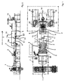
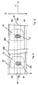
- the Fig. 1 to 4 show a device for producing a contour cut in a sheet metal strip or for the production of sheet metal blanks with a predetermined shape.
- the reference numeral 1 denotes a reel which serves to receive a sheet-metal strip (not shown here) in the form of a coil or a coil. Downstream of the reel 1 there is a roller straightening device 2.
- the reference numeral 3 generally designates a conveyor device.
- the conveyor device 3 comprises a first transport device 4, downstream of which, ie downstream in a transport direction T, a second transport device 5. Between a first end E1 of the first transport device 4 and a second end E2 of the second transport device 5, a first opening D1 is formed, which has the shape of a slot.
- the first 4 and the second transport means 5 are designed here in the manner of conveyor belts.
- the first E1 and the second end E2 of the transport devices 4, 5 can be moved in the same direction and back and forth in and against a transport direction T.
- a breakthrough movement or adjusting device not shown here is provided.
- the conveying device 3 comprises in parallel arrangement to the first transport means 4, a third transport means 6 and in parallel arrangement to the second transport means 5, a fourth transport means 7.
- a fifth transport means 8 and a sixth transport means 9 is provided , Not shown here in detail opposite ends of the third to sixth transport device 6, 7, 8, 9, as the first E1 and second ends E2 in or against the transport direction T by means of the adjusting device out and to be moved.
- a second opening formed between the third 6 and the fourth transporting device 7 (not shown here) as well as a third opening (not shown here) formed between the fifth 8 and the sixth transporting device 9 can be moved independently of one another.
- the reference numeral 10 denotes a first laser cutting device
- the reference numeral 11 denotes a downstream second laser cutting device and the reference numeral 12, a third laser cutting device 12 arranged next to the first laser cutting device 10.
- the laser cutting devices 10, 11, 12 are surrounded by a protective housing 13. Downstream of the conveyor 3 there is a robot 14 with which the sheet metal blanks 15 cut from the sheet metal strip are stacked to form transport stacks.
- Each of the laser cutting devices 10, 11, 12 has in each case a laser cutting unit 10a, 11a, 12a, which are each accommodated on a carriage 10b, 11b, 12b which can be moved back and forth in the transporting direction T. Furthermore, each of the laser cutting units 10a, 11a, 12a is movable perpendicular to the transport direction T on the respective carriage 10b, 11b, 12b.
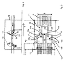
- the first laser cutting unit 10a is movable in a first working area A1, which has a first width B1 and a first length L1.
- a third working area A3 of the third laser cutting unit 12 located in a direction perpendicular to the transporting direction T has a third length L3 and a third width B3.
- the first L1 and the third length L3 may correspond to each other.
- the first width B1 and the third width B3 can be the same size be.
- the third working area extends with its third length L3 over the first length L1 of the first working area A1.
- the first A1 and the third working area A3 are not offset from one another in the direction perpendicular to the transport direction, they extend - in particular in FIG Fig. 3 is shown - in the transport direction T over an approximately identical section of the conveyor device.
- the first 10a and the third laser cutter 12a can be simultaneously moved in the adjacent first A1 and third work areas A3.
- the corresponding first and third openings of the transport device can be automatically moved along.
- the arrangement of two or more working areas perpendicular to the transport direction side by side contributes to a particularly short in the transport direction design of the device. Apart from that, the production speed of contour sheets can be increased.
- a second working area A2 of the second laser cutting unit 11a is located approximately in the center of the conveying device 3.
- the second working area A2 has a second length L2 and a second width B2.
- the first B1, the second B2 and the third width B3 are each smaller than a width B of a metal strip or the conveyor 3. As out Fig. 3 is apparent, the first B1 and the third width B3 are selected so that they overlap with the second width B2 of the downstream downstream second working area A2. In this case, B1 + B2 + B3> B applies.
- the second working area A2 is in Transport direction T with a small distance A from the first A1 and third working area A3 spaced.
- the second working area A2 arranged approximately centrally with respect to the sheet-metal strip BB is arranged upstream of the first A1 and of the third working area A3.
- the sheet-metal strip BB is again subdivided into three processing strips whose widths correspond to the first width B1 of the first working area A1, the second width B2 of the second working area A2 and the third width B3 of the third working area A3.
- the processing strips overlap marginally.
- a marginal overlap region is designated by the reference symbols U1 and U2.
- the sheet-metal strip BB is first performed by the second working area A2.
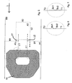
- the second laser cutting unit 11a generates the partial cuts falling in the second processing strip, of which a first partial section into the 6 and 7 designated T1.
- the first partial section T1 has at its end a first arc Bo1 slightly deviating from the desired contour.
- the sheet metal strip BB enters the first A1 and third working area A3.
- the third laser cutting unit 11 a designated by the reference numeral T2 second partial section is generated, which with a slightly different from the desired contour second arc Bo2 uses.
- Fig. 7 is ensured by the expiration of the first partial section T1 with a first arc Bo1 and the insertion of the second partial section T2 with a second arc Bo2 even in the case of an offset that the first T1 and the second partial section T2 are interconnected.
- a safe and complete separation of the sheet metal plate 15 can be ensured by the other components of the metal strip BB.
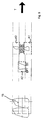
- Fig. 8 shows by way of example the movement sequence of a first 10a, second 11a and third laser cutting unit 12a, as it is necessary for the production of the sheet metal plate 15 shown.
- the second working area A2 is located upstream of the first A1 and the third working area A3.
- the in Fig. 8 traced apparent path of movement, which extends from a first starting point S1 to a first end point EP1.
- the further trajectories designated by the starting points S2 and S3 are simultaneously traversed downstream. This allows the links in Fig. 8 shown contour can be produced quickly and efficiently.
- the metal strip BB at a speed in the range from 5 to 100 m / min, preferably 20 to 50 m / min, in the transport direction T to move at a constant speed.
- the laser cutting units 10a, 11a, 12a can be moved at a speed in the range of 20 to 60 m / min.
- a specific belt speed can first be predetermined. Then, with a predetermined contour of the sheet metal blanks 15, the movements of the laser cutting units 10a, 11a, 12a can be calculated.
- FIGS. 9 and 10 show by way of example the advantageous effects of an adjustment of the metal strip BB in a direction perpendicular to the transport direction T extending transverse direction Q.
- the sheet metal strip BB is arranged centrally with respect to the outer boundaries G1, G2 of the working areas of the laser cutting devices 10, 11, 12.
- a central axis M extending centrally between the boundaries G1, G2 coincides with a further central axis (not shown here) of the sheet-metal strip BB.
- an inner contour K falls within the first and second working ranges of the first and second laser cutting devices (not shown here) given by the first B1 and second width B2. Ie. the inner contour K must be cut here by the interaction of two laser cutting units.
- the sheet-metal strip BB is adjusted with respect to the outer boundaries G1, G2 in the transverse direction Q such that the inner contour K falls only in the second working region defined by the second width B2.
- the inner contour K can be produced only by the action of the second laser cutting device (not shown here).
- the programming effort for Production of the inner contour K decreases, improves the shape of the inner contour K and also the process reliability can be increased.
- more than three laser cutting units may be used in accordance with the subject invention.
- Upstream or downstream two further laser cutting devices may be provided which overlap the two gaps between the three aforementioned laser cutting units.
- the two upstream or downstream provided further laser cutting units can be arranged perpendicular to the transport direction next to each other.
- a conveyor device with five revolving apertures is provided, which is assigned to one of the laser cutting units.
Landscapes
- Engineering & Computer Science (AREA)
- Physics & Mathematics (AREA)
- Optics & Photonics (AREA)
- Mechanical Engineering (AREA)
- Plasma & Fusion (AREA)
- Laser Beam Processing (AREA)
Claims (22)
- Procédé pour la réalisation d'une découpe de contour dans une bande de tôle (BB) transportée continuellement dans un sens de transport (T) au moyen d'un convoyeur (3) selon les étapes suivantes:division de la bande de tôle (BB) par rapport à sa largeur (B) en au moins trois bandes d'usinage chevauchantes s'étendant dans le sens de transport (T), une première bande d'usinage présentant une première largeur (B1), une deuxième bande d'usinage une deuxième largeur (B2) et une troisième bande d'usinage une troisième largeur (B3), la première (B1) et la deuxième largeur (B2) étant respectivement inférieures à une largeur (B) de la bande de tôle (BB), et où la deuxième bande d'usinage s'étend approximativement au centre et recouvre au bord la première et une troisième bande d'usinage,mise à disposition d'un premier dispositif de découpe au laser (10) affecté à la première bande d'usinage, dont la première plage d'opération (A1) est limitée par la première largeur (B1) et, dans le sens de transport (T), par une première longueur (L1),mise à disposition d'un deuxième dispositif de découpe au laser (11) affecté à la deuxième bande d'usinage, dont la deuxième plage d'opération (A2) suivante en aval ou en amont de la première plage d'opération (A1) est limitée par la deuxième largeur (B2) et, dans le sens de transport (T), par une deuxième longueur (L2),mise à disposition d'un troisième dispositif de découpe au laser (12) affecté à la troisième bande d'usinage, dont la troisième plage d'opération (A3) est limitée par la troisième largeur (B3) et, dans le sens de transport (T), par une troisième longueur (L3), la troisième plage d'opération (A3) du troisième dispositif de découpe au laser (12) se trouvant dans un sens vertical par rapport au sens de transport (T), près de la première plage d'opération (A1) du premier dispositif de découpe au laser, etcommande du premier (10), deuxième (11) et troisième dispositif de découpe au laser (12) de façon à ce qu'au moins une première coupe partielle (T1) de la découpe de contour soit réalisée au moyen du dispositif de découpe au laser (10, 11, 12) situé en amont, et qu'au moins une deuxième coupe partielle (T2) restante pour la réalisation de la découpe de contour soit réalisée par suite de la première coupe partielle (T1) puis par le dispositif de découpe au laser (10, 11) situé en aval.
- Procédé selon la revendication 1, où une première ouverture (D1) prévue sur le convoyeur (3) est déplacée dans la même direction en alignement sur un premier faisceau laser diffusé par le premier dispositif de découpe au laser (10), afin que le premier faisceau laser traverse la première ouverture (D1), où une deuxième ouverture prévue sur le convoyeur (3) est déplacée dans la même direction en alignement sur un deuxième faisceau laser diffusé par le deuxième dispositif de découpe au laser (11), afin que le deuxième faisceau laser traverse la deuxième ouverture, et où une troisième ouverture prévue sur le convoyeur (3) est déplacée dans la même direction en alignement sur le troisième faisceau laser, afin qu'un troisième faisceau laser diffusé par le troisième dispositif de découpe au laser (12) traverse la troisième ouverture.
- Procédé selon l'une des revendications précédentes, où le convoyeur (3) comprend, correspondant à la première bande d'usinage, un premier dispositif de transport (4) et un deuxième dispositif de transport (5) suivant dans le sens de transport (T), où la première ouverture (D1) est réalisée entre une première extrémité (E1) du premier dispositif de transport (4) et une deuxième extrémité (E2) opposée du deuxième dispositif de transport (5), et où le déplacement dans la même direction de la première ouverture (D1) est généré par un déplacement de même sens de la première (E1) et de la deuxième extrémité (E2) dans ou opposé au sens de transport (T).
- Procédé selon l'une des revendications précédentes, où le convoyeur (3) comprend, correspondant à la deuxième bande d'usinage, un troisième dispositif de transport (6) disposé parallèlement au premier dispositif de transport (4) et un quatrième dispositif de transport (7) disposé parallèlement au deuxième dispositif de transport (5), où la deuxième ouverture est réalisée entre une troisième extrémité du troisième dispositif de transport (6) et une quatrième extrémité opposée du quatrième dispositif de transport (7), et où le déplacement dans la même direction de la deuxième ouverture est généré par un déplacement de même sens de la troisième et de la quatrième extrémité dans ou opposé au sens de transport (T).
- Procédé selon l'une des revendications précédentes, où le convoyeur (3) comprend, correspondant à la troisième bande d'usinage, un cinquième dispositif de transport (8) disposé parallèlement au troisième dispositif de transport (6) et un sixième dispositif de transport (9) disposé parallèlement au quatrième dispositif de transport (7), où la troisième ouverture est réalisée entre une cinquième extrémité du cinquième dispositif de transport (8) et une sixième extrémité opposée du sixième dispositif de transport (9), et où le déplacement dans la même direction de la troisième ouverture est généré par un déplacement de même sens de la cinquième et de la sixième extrémité dans ou opposé au sens de transport (T).
- Procédé selon l'une des revendications précédentes, où la bande de tôle (BB) est déplacée à une vitesse de transport essentiellement constante dans le sens de transport (T).
- Procédé selon l'une des revendications précédentes où, lors de la réalisation de la découpe de contour, une première courbe (Bo1) différente du contour défini de la découpe de contour est découpée à une extrémité de la première coupe partielle (T1), et où la deuxième coupe partielle (T2) commence avant l'une des extrémités de la première coupe partielle (T1) et est guidée dans une deuxième courbe (Bo2) arrivant sur le contour défini.
- Procédé selon l'une des revendications précédentes, où une position transversale de la bande de tôle (BB) allant vers le sens de transport (T) est définie de façon à ce que la découpe de contour soit réalisable avec un nombre minimal de coupes partielles (T1, T2).
- Dispositif pour la réalisation d'une découpe de contour dans une bande de tôle (BB),
avec un convoyeur (3) pour le transport continu de la bande de tôle (BB) dans un sens de transport (T), où la bande de tôle (BB) est divisée par rapport à sa largeur (B) en au moins trois bandes d'usinage chevauchantes s'étendant dans le sens de transport (T), où une première bande d'usinage présente une première largeur (B1), une deuxième bande d'usinage une deuxième largeur (B2) et une troisième bande d'usinage une troisième largeur (B3), où la première (B1) et la deuxième largeur (B2) sont respectivement inférieures à une largeur (B) de la bande de tôle (BB), et où la deuxième bande d'usinage s'étend approximativement au centre et recouvre au bord la première et une troisième bande d'usinage présentant une troisième largeur (B3),
un premier dispositif de découpe au laser (10) affecté à la première bande d'usinage, dont la première plage d'opération (A1) est limitée par la première largeur (B1) et, dans le sens de transport (T), par une première longueur (L1),
un deuxième dispositif de découpe au laser (11) affecté à la deuxième bande d'usinage, dont la deuxième plage d'opération (A2) suivante en aval ou en amont de la première plage d'opération (A1) est limitée par la deuxième largeur (B2) et, dans le sens de transport (T), par une deuxième longueur (L2),
un troisième dispositif de découpe au laser (12) affecté à la troisième bande d'usinage, dont la troisième plage d'opération (A3) est limitée par la troisième largeur (B3) et, dans le sens de transport (T), par une troisième longueur (L3), la troisième plage d'opération (A3) du troisième dispositif de découpe au laser (12) se trouvant dans un sens vertical par rapport au sens de transport (T), près de la première plage d'opération (A1) du premier dispositif de découpe au laser et
un dispositif de commande pour commander le premier (10), le deuxième (11) et le troisième dispositif de découpe au laser (12) de façon à ce qu'au moins une première coupe partielle (T1) de la découpe de contour soit réalisée au moyen du dispositif de découpe au laser (10, 11, 12) situé en amont, et qu'au moins une deuxième coupe partielle (T2) restante pour la réalisation de la découpe de contour soit réalisée par suite de la première coupe partielle (T1) puis par le dispositif de découpe au laser (10, 11) situé en aval. - Dispositif selon la revendication 9, où un premier dispositif de déplacement d'ouverture est prévu pour le déplacement dans la même direction d'une première ouverture (D1) prévue sur le convoyeur (3) en alignement sur un premier faisceau laser diffusé par le premier dispositif de découpe au laser (10), afin que le premier faisceau laser traverse la première ouverture (D1), où un deuxième dispositif de déplacement d'ouverture est prévu pour le déplacement dans la même direction d'une deuxième ouverture prévue sur le convoyeur (3) en alignement sur un deuxième faisceau laser diffusé par le deuxième dispositif de découpe au laser (11), afin que le deuxième faisceau laser traverse la deuxième ouverture, et où un troisième dispositif de déplacement d'ouverture est prévu pour le déplacement dans la même direction d'une troisième ouverture prévue sur le convoyeur (3) en alignement sur le troisième faisceau laser, afin qu'un troisième faisceau laser diffusé par le troisième dispositif de découpe au laser (12) traverse la troisième ouverture.
- Dispositif selon l'une des revendications 9 ou 10, où le premier (10), le deuxième (11) et le troisième dispositif de découpe au laser (12) sont commandés au moyen du dispositif de commande de façon à ce qu'au moins une première coupe partielle (T1) de la découpe de contour soit réalisée avec un dispositif de découpe au laser (10, 11, 12) situé en amont, et qu'au moins une deuxième coupe partielle (T2) restante pour la réalisation de la découpe de contour soit réalisée par suite de la première coupe partielle (T1) puis par le deuxième dispositif de découpe au laser (11).
- Dispositif selon l'une des revendications 9 à 11, où le convoyeur (3) comprend, correspondant à la première bande d'usinage, un premier dispositif de transport (4) et un deuxième dispositif de transport (5) suivant dans le sens de transport (T), où la première ouverture (D1) est réalisée entre une première extrémité (E1) du premier dispositif de transport (4) et une deuxième extrémité (E2) opposée du deuxième dispositif de transport (5), et où le déplacement dans la même direction de la première ouverture (D1) est provoqué par un déplacement de même sens, généré au moyen du premier dispositif de déplacement d'ouverture, de la première (E1) et de la deuxième extrémité (E2) dans ou opposé au sens de transport (T).
- Dispositif selon l'une des revendications 9 à 12, où le convoyeur (3) comprend, correspondant à la deuxième bande d'usinage, un troisième dispositif de transport (6) disposé parallèlement au premier dispositif de transport (4) et un quatrième dispositif de transport (7) disposé parallèlement au deuxième dispositif de transport (5), où la deuxième ouverture est réalisée entre une troisième extrémité du troisième dispositif de transport (6) et une quatrième extrémité opposée du quatrième dispositif de transport (7), et où le déplacement dans la même direction de la deuxième ouverture est provoqué par un déplacement de même sens, généré au moyen du deuxième dispositif de déplacement d'ouverture, de la troisième et de la quatrième extrémité dans ou opposé au sens de transport (T).
- Dispositif selon l'une des revendications 9 à 13, où le convoyeur (3) comprend, correspondant à la troisième bande d'usinage, un cinquième dispositif de transport (8) disposé parallèlement au troisième dispositif de transport (6) et un sixième dispositif de transport (9) disposé parallèlement au quatrième dispositif de transport (7), où la troisième ouverture est réalisée entre une cinquième extrémité du cinquième dispositif de transport (8) et une sixième extrémité opposée du sixième dispositif de transport (9), et où le déplacement dans la même direction de la troisième ouverture est généré par un déplacement de même sens, généré au moyen du troisième dispositif de déplacement d'ouverture, de la cinquième et de la sixième extrémité dans ou opposé au sens de transport (T).
- Dispositif selon l'une des revendications 9 à 14, où un dispositif de réglage est prévu pour le réglage de la vitesse de transport.
- Dispositif selon l'une des revendications 9 à 15, où un dispositif d'ajustage est prévu pour l'ajustage d'un dérouleur (1) recevant la bande de tôle (BB) dans un sens transversal (Q) par rapport au sens de transport (T).
- Dispositif selon l'une des revendications 9 à 16, où le dispositif d'ajustage comprend un guidage latéral de bande réglable dans le sens transversal (Q).
- Dispositif selon l'une des revendications 9 à 17, où une position transversale de la bande de tôle (BB) est ajustable au moyen du dispositif d'ajustage de façon à ce que la découpe de contour soit réalisable avec un nombre minimal de coupes partielles (T1, T2).
- Dispositif selon l'une des revendications 9 à 18, où le premier (10), le deuxième (11) et le troisième dispositif de découpe au laser (12) sont réalisés comme unités de montage, de préférence de type identique.
- Dispositif selon l'une des revendications 9 à 19, où le premier (10), le deuxième (11) et le troisième dispositif de découpe au laser (12) sont montés de manière antivibratoire par rapport au convoyeur (3).
- Dispositif selon l'une des revendications 9 à 20, où au moins une des unités de montage est maintenue ajustable par rapport au convoyeur (3).
- Dispositif selon l'une des revendications 9 à 21, où d'autres dispositifs de découpe au laser sont prévus dans la zone des bords latéraux du convoyeur (3) pour la réalisation d'une coupe des bords de la bande de tôle.
Applications Claiming Priority (3)
| Application Number | Priority Date | Filing Date | Title |
|---|---|---|---|
| DE102010039538 | 2010-08-19 | ||
| DE102010041542 | 2010-09-28 | ||
| DE102010042067A DE102010042067A1 (de) | 2010-08-19 | 2010-10-06 | Verfahren und Vorrichtung zum Herstellen eines Konturschnitts in einem Blechband |
Publications (2)
| Publication Number | Publication Date |
|---|---|
| EP2420344A1 EP2420344A1 (fr) | 2012-02-22 |
| EP2420344B1 true EP2420344B1 (fr) | 2013-05-22 |
Family
ID=44674229
Family Applications (1)
| Application Number | Title | Priority Date | Filing Date |
|---|---|---|---|
| EP11176675.4A Active EP2420344B1 (fr) | 2010-08-19 | 2011-08-05 | Procédé et dispositif de découpe d'un contour dans une bande de tôle |
Country Status (3)
| Country | Link |
|---|---|
| EP (1) | EP2420344B1 (fr) |
| DE (1) | DE102010042067A1 (fr) |
| ES (1) | ES2422682T3 (fr) |
Cited By (6)
| Publication number | Priority date | Publication date | Assignee | Title |
|---|---|---|---|---|
| CN104785657A (zh) * | 2015-04-15 | 2015-07-22 | 广东中冶合创科技有限公司 | 双进料的自动冲压落料生产线 |
| DE202017002363U1 (de) | 2017-04-27 | 2017-05-18 | Maximilian Setterl | Vorrichtung zum Transportieren und Bearbeiten von Halbzeugen |
| EP3181248A1 (fr) | 2015-12-18 | 2017-06-21 | Muhr und Bender KG | Procede et installation de fabrication d'une platine de tole |
| CN107735207A (zh) * | 2015-06-12 | 2018-02-23 | 舒勒自动化有限及两合公司 | 用于生产金属板料的方法和设备 |
| DE102017004318B3 (de) * | 2017-04-27 | 2018-04-05 | Maximilian Setterl | Vorrichtung und Verfahren zum Transportieren und Bearbeiten von Halbzeugen |
| DE102017000539A1 (de) | 2017-01-23 | 2018-07-26 | ALS Alu Laser Service | Vorrichtung an einer Laserschneidvorrichtung |
Families Citing this family (12)
| Publication number | Priority date | Publication date | Assignee | Title |
|---|---|---|---|---|
| FR3001906B1 (fr) | 2013-02-11 | 2016-01-01 | Dimeco Alipresse | Procede de decoupage de pieces dans une bande de matiere et machine de decoupage mettant en oeuvre ledit procede |
| DE102013203383A1 (de) | 2013-02-28 | 2014-08-28 | Schuler Automation Gmbh & Co. Kg | Verfahren zum Schneiden einer Blechplatine |
| DE102013203386A1 (de) * | 2013-02-28 | 2014-08-28 | Schuler Automation Gmbh & Co. Kg | Vorrichtung zur Herstellung von Blechplatinen |
| DE102013203385A1 (de) * | 2013-02-28 | 2014-08-28 | Schuler Automation Gmbh & Co. Kg | Verfahren zum Schneiden einer Blechplatine mit einer vorgegebenen Kontur |
| CN103600170B (zh) | 2013-04-28 | 2015-08-26 | 宝山钢铁股份有限公司 | 一种纵向金属板上下料与切割方法及其系统 |
| CN103600171B (zh) | 2013-04-28 | 2015-12-09 | 宝山钢铁股份有限公司 | 一种金属板上下料及切割的方法及系统 |
| DE102013210878A1 (de) | 2013-06-11 | 2014-12-11 | Schuler Automation Gmbh & Co. Kg | Verfahren und Vorrichtung zur Herstellung eines Blechformteils |
| PL2907613T3 (pl) * | 2014-02-06 | 2021-07-12 | Preco, Inc. | Sposób laserowego przetwarzania złożonego wzoru na rolce ciągłej |
| US20160346874A1 (en) * | 2015-05-27 | 2016-12-01 | Preco, Inc. | Singulation conveyor |
| CN110757005B (zh) * | 2019-10-23 | 2023-04-28 | 苏州普热斯勒先进成型技术有限公司 | 一种用于板材分区切割的激光切割设备及切割方法 |
| DE102020111238A1 (de) | 2020-04-24 | 2021-10-28 | Schuler Pressen Gmbh | Verfahren und Vorrichtung zum Vereinzeln von Platinen |
| CN113751899A (zh) * | 2021-11-09 | 2021-12-07 | 张家港市棋瑞德机械制造有限公司 | 一种基于激光切割的板材切割设备 |
Family Cites Families (7)
| Publication number | Priority date | Publication date | Assignee | Title |
|---|---|---|---|---|
| US5365816A (en) * | 1993-06-22 | 1994-11-22 | Design Systems, Inc. | Beam cutter |
| DE19620391C2 (de) * | 1996-05-21 | 2001-12-13 | Carl Ingolf Lange | Bearbeitungsvorrichtung für flache Gegenstände |
| DE10235903B4 (de) * | 2002-08-06 | 2004-09-16 | Müller Weingarten AG | Verfahren und Vorrichtung zum Schneiden von Blechplatinen mit einem Schneidstrahl |
| DE102004034256B4 (de) | 2004-07-14 | 2007-04-05 | Schuler Automation Gmbh & Co.Kg | Vorrichtung zum Schneiden von Blech |
| JP5693971B2 (ja) | 2008-02-20 | 2015-04-01 | レーザーコイル・テクノロジーズ、エルエルシーLasercoil Technologies, LLC | 高速切断のための順送レーザブランキング装置 |
| ITMO20080193A1 (it) * | 2008-07-14 | 2010-01-15 | Scm Group Spa | Apparato e metodo per sezionare pannelli |
| WO2010085486A1 (fr) | 2009-01-20 | 2010-07-29 | Automatic Feed Company | Découpage au laser à partir d'un système de convoyeur de feuillard enroulé |
-
2010
- 2010-10-06 DE DE102010042067A patent/DE102010042067A1/de not_active Ceased
-
2011
- 2011-08-05 EP EP11176675.4A patent/EP2420344B1/fr active Active
- 2011-08-05 ES ES11176675T patent/ES2422682T3/es active Active
Cited By (9)
| Publication number | Priority date | Publication date | Assignee | Title |
|---|---|---|---|---|
| CN104785657A (zh) * | 2015-04-15 | 2015-07-22 | 广东中冶合创科技有限公司 | 双进料的自动冲压落料生产线 |
| CN104785657B (zh) * | 2015-04-15 | 2016-10-05 | 广东中冶合创科技有限公司 | 双进料的自动冲压落料生产线 |
| CN107735207A (zh) * | 2015-06-12 | 2018-02-23 | 舒勒自动化有限及两合公司 | 用于生产金属板料的方法和设备 |
| EP3181248A1 (fr) | 2015-12-18 | 2017-06-21 | Muhr und Bender KG | Procede et installation de fabrication d'une platine de tole |
| US9993859B2 (en) | 2015-12-18 | 2018-06-12 | Muhr Und Bender Kg | Sheet metal blank |
| DE102017000539A1 (de) | 2017-01-23 | 2018-07-26 | ALS Alu Laser Service | Vorrichtung an einer Laserschneidvorrichtung |
| DE202017002363U1 (de) | 2017-04-27 | 2017-05-18 | Maximilian Setterl | Vorrichtung zum Transportieren und Bearbeiten von Halbzeugen |
| DE102017004318B3 (de) * | 2017-04-27 | 2018-04-05 | Maximilian Setterl | Vorrichtung und Verfahren zum Transportieren und Bearbeiten von Halbzeugen |
| WO2018197045A1 (fr) | 2017-04-27 | 2018-11-01 | Maximilian Setterl | Dispositif et procédé permettant de transporter et d'usiner des demi-produits |
Also Published As
| Publication number | Publication date |
|---|---|
| ES2422682T3 (es) | 2013-09-13 |
| EP2420344A1 (fr) | 2012-02-22 |
| DE102010042067A1 (de) | 2012-02-23 |
Similar Documents
| Publication | Publication Date | Title |
|---|---|---|
| EP2420344B1 (fr) | Procédé et dispositif de découpe d'un contour dans une bande de tôle | |
| EP3083127B1 (fr) | Machine pour séparer par usinage des pièces en forme de plaques et son utilisation | |
| DE102013226818B4 (de) | Maschine zum trennenden Bearbeiten von plattenförmigen Werkstücken | |
| EP3268162B1 (fr) | Machine pour séparer par usinage des pièces en forme de plaques | |
| EP2543452B1 (fr) | Dispositif de pliage pour pièces usinées en forme de tige | |
| EP2441547B1 (fr) | Procédé de séparation de pièces découpées et chutes lors de la découpe au laser d'une tôle | |
| EP2008736B1 (fr) | Machine-outil et procédé destinés à l'évacuation d'une partie d'une pièce à usiner | |
| EP1683601B1 (fr) | Méthode de découpage laser de tôles brutes et dispositif de découpe laser pour mettre en oeuvre ce procédé | |
| EP3528996B1 (fr) | Procédé permettant de prévoir une tendance au basculement d'une partie de pièce découpée et machine d'usinage pour l'usinage par découpage d'une pièce en forme de plaque | |
| EP2158055B1 (fr) | Dispositif de sciage et procédé d'usinage par sciage d'une pièce à usiner | |
| EP1716990B1 (fr) | Machine à travailler le bois opérant en continu avec unité d'usinage | |
| EP0595253B1 (fr) | Dispositif volant pour couper de la matière de faible épaisseur avec rayonnement du laser | |
| DE19853366A1 (de) | Vorrichtung und Verfahren zum Umformen | |
| EP1495816B1 (fr) | Outil de pliage à segments de butée de la pièce réglables ainsi que machine à plier comprenant un tel outil de pliage | |
| EP3402024A1 (fr) | Dispositif de traitement de câbles | |
| EP1002594A2 (fr) | Procédé et dipositif pour former une pièce | |
| EP2921240B1 (fr) | Outil pour une poinçonneuse universelle avec un élément d'outil flottant et poinçonneuse universelle | |
| EP1387743B1 (fr) | Unite de detourage pour une machine continue commandee par programme | |
| WO2016198612A1 (fr) | Procédé et dispositif de fabrication d'un flan de tôle | |
| DE10064888B4 (de) | Verfahren und Vorrichtung zum Schneiden von Blechplatinen | |
| EP3684569B1 (fr) | Procédé de découpe d'une pièce de préférence en forme de panneau | |
| EP0515808B1 (fr) | Méthode d'usinage utilisant le rayonnement pour bandes doubles | |
| DE102017004318B3 (de) | Vorrichtung und Verfahren zum Transportieren und Bearbeiten von Halbzeugen | |
| WO2021013810A1 (fr) | Outil et procédé pour l'usinage de pièces en forme de plaques, en particulier de tôles | |
| DE3442466C2 (fr) |
Legal Events
| Date | Code | Title | Description |
|---|---|---|---|
| AK | Designated contracting states |
Kind code of ref document: A1 Designated state(s): AL AT BE BG CH CY CZ DE DK EE ES FI FR GB GR HR HU IE IS IT LI LT LU LV MC MK MT NL NO PL PT RO RS SE SI SK SM TR |
|
| AX | Request for extension of the european patent |
Extension state: BA ME |
|
| PUAI | Public reference made under article 153(3) epc to a published international application that has entered the european phase |
Free format text: ORIGINAL CODE: 0009012 |
|
| 17P | Request for examination filed |
Effective date: 20120306 |
|
| GRAP | Despatch of communication of intention to grant a patent |
Free format text: ORIGINAL CODE: EPIDOSNIGR1 |
|
| RIC1 | Information provided on ipc code assigned before grant |
Ipc: B23K 26/08 20060101AFI20120430BHEP Ipc: B26F 1/38 20060101ALI20120430BHEP Ipc: B23K 26/38 20060101ALI20120430BHEP Ipc: B23Q 39/02 20060101ALI20120430BHEP Ipc: B23K 37/02 20060101ALI20120430BHEP Ipc: B23K 37/04 20060101ALI20120430BHEP |
|
| GRAS | Grant fee paid |
Free format text: ORIGINAL CODE: EPIDOSNIGR3 |
|
| GRAP | Despatch of communication of intention to grant a patent |
Free format text: ORIGINAL CODE: EPIDOSNIGR1 |
|
| GRAA | (expected) grant |
Free format text: ORIGINAL CODE: 0009210 |
|
| AK | Designated contracting states |
Kind code of ref document: B1 Designated state(s): AL AT BE BG CH CY CZ DE DK EE ES FI FR GB GR HR HU IE IS IT LI LT LU LV MC MK MT NL NO PL PT RO RS SE SI SK SM TR |
|
| REG | Reference to a national code |
Ref country code: GB Ref legal event code: FG4D Free format text: NOT ENGLISH |
|
| REG | Reference to a national code |
Ref country code: CH Ref legal event code: EP |
|
| REG | Reference to a national code |
Ref country code: AT Ref legal event code: REF Ref document number: 612943 Country of ref document: AT Kind code of ref document: T Effective date: 20130615 |
|
| REG | Reference to a national code |
Ref country code: IE Ref legal event code: FG4D Free format text: LANGUAGE OF EP DOCUMENT: GERMAN |
|
| REG | Reference to a national code |
Ref country code: DE Ref legal event code: R096 Ref document number: 502011000767 Country of ref document: DE Effective date: 20130718 |
|
| REG | Reference to a national code |
Ref country code: ES Ref legal event code: FG2A Ref document number: 2422682 Country of ref document: ES Kind code of ref document: T3 Effective date: 20130913 |
|
| REG | Reference to a national code |
Ref country code: LT Ref legal event code: MG4D |
|
| PG25 | Lapsed in a contracting state [announced via postgrant information from national office to epo] |
Ref country code: SI Free format text: LAPSE BECAUSE OF FAILURE TO SUBMIT A TRANSLATION OF THE DESCRIPTION OR TO PAY THE FEE WITHIN THE PRESCRIBED TIME-LIMIT Effective date: 20130522 Ref country code: LT Free format text: LAPSE BECAUSE OF FAILURE TO SUBMIT A TRANSLATION OF THE DESCRIPTION OR TO PAY THE FEE WITHIN THE PRESCRIBED TIME-LIMIT Effective date: 20130522 Ref country code: PT Free format text: LAPSE BECAUSE OF FAILURE TO SUBMIT A TRANSLATION OF THE DESCRIPTION OR TO PAY THE FEE WITHIN THE PRESCRIBED TIME-LIMIT Effective date: 20130923 Ref country code: NO Free format text: LAPSE BECAUSE OF FAILURE TO SUBMIT A TRANSLATION OF THE DESCRIPTION OR TO PAY THE FEE WITHIN THE PRESCRIBED TIME-LIMIT Effective date: 20130822 Ref country code: FI Free format text: LAPSE BECAUSE OF FAILURE TO SUBMIT A TRANSLATION OF THE DESCRIPTION OR TO PAY THE FEE WITHIN THE PRESCRIBED TIME-LIMIT Effective date: 20130522 Ref country code: SE Free format text: LAPSE BECAUSE OF FAILURE TO SUBMIT A TRANSLATION OF THE DESCRIPTION OR TO PAY THE FEE WITHIN THE PRESCRIBED TIME-LIMIT Effective date: 20130522 Ref country code: GR Free format text: LAPSE BECAUSE OF FAILURE TO SUBMIT A TRANSLATION OF THE DESCRIPTION OR TO PAY THE FEE WITHIN THE PRESCRIBED TIME-LIMIT Effective date: 20130823 |
|
| REG | Reference to a national code |
Ref country code: NL Ref legal event code: VDEP Effective date: 20130522 |
|
| PG25 | Lapsed in a contracting state [announced via postgrant information from national office to epo] |
Ref country code: BG Free format text: LAPSE BECAUSE OF FAILURE TO SUBMIT A TRANSLATION OF THE DESCRIPTION OR TO PAY THE FEE WITHIN THE PRESCRIBED TIME-LIMIT Effective date: 20130822 Ref country code: RS Free format text: LAPSE BECAUSE OF FAILURE TO SUBMIT A TRANSLATION OF THE DESCRIPTION OR TO PAY THE FEE WITHIN THE PRESCRIBED TIME-LIMIT Effective date: 20130522 Ref country code: HR Free format text: LAPSE BECAUSE OF FAILURE TO SUBMIT A TRANSLATION OF THE DESCRIPTION OR TO PAY THE FEE WITHIN THE PRESCRIBED TIME-LIMIT Effective date: 20130522 Ref country code: PL Free format text: LAPSE BECAUSE OF FAILURE TO SUBMIT A TRANSLATION OF THE DESCRIPTION OR TO PAY THE FEE WITHIN THE PRESCRIBED TIME-LIMIT Effective date: 20130522 |
|
| PG25 | Lapsed in a contracting state [announced via postgrant information from national office to epo] |
Ref country code: LV Free format text: LAPSE BECAUSE OF FAILURE TO SUBMIT A TRANSLATION OF THE DESCRIPTION OR TO PAY THE FEE WITHIN THE PRESCRIBED TIME-LIMIT Effective date: 20130522 |
|
| PG25 | Lapsed in a contracting state [announced via postgrant information from national office to epo] |
Ref country code: EE Free format text: LAPSE BECAUSE OF FAILURE TO SUBMIT A TRANSLATION OF THE DESCRIPTION OR TO PAY THE FEE WITHIN THE PRESCRIBED TIME-LIMIT Effective date: 20130522 Ref country code: DK Free format text: LAPSE BECAUSE OF FAILURE TO SUBMIT A TRANSLATION OF THE DESCRIPTION OR TO PAY THE FEE WITHIN THE PRESCRIBED TIME-LIMIT Effective date: 20130522 Ref country code: SK Free format text: LAPSE BECAUSE OF FAILURE TO SUBMIT A TRANSLATION OF THE DESCRIPTION OR TO PAY THE FEE WITHIN THE PRESCRIBED TIME-LIMIT Effective date: 20130522 Ref country code: CZ Free format text: LAPSE BECAUSE OF FAILURE TO SUBMIT A TRANSLATION OF THE DESCRIPTION OR TO PAY THE FEE WITHIN THE PRESCRIBED TIME-LIMIT Effective date: 20130522 |
|
| BERE | Be: lapsed |
Owner name: SCHULER AUTOMATION G.M.B.H. & CO. KG Effective date: 20130831 |
|
| PG25 | Lapsed in a contracting state [announced via postgrant information from national office to epo] |
Ref country code: NL Free format text: LAPSE BECAUSE OF FAILURE TO SUBMIT A TRANSLATION OF THE DESCRIPTION OR TO PAY THE FEE WITHIN THE PRESCRIBED TIME-LIMIT Effective date: 20130522 Ref country code: RO Free format text: LAPSE BECAUSE OF FAILURE TO SUBMIT A TRANSLATION OF THE DESCRIPTION OR TO PAY THE FEE WITHIN THE PRESCRIBED TIME-LIMIT Effective date: 20130522 |
|
| PLBE | No opposition filed within time limit |
Free format text: ORIGINAL CODE: 0009261 |
|
| STAA | Information on the status of an ep patent application or granted ep patent |
Free format text: STATUS: NO OPPOSITION FILED WITHIN TIME LIMIT |
|
| 26N | No opposition filed |
Effective date: 20140225 |
|
| PG25 | Lapsed in a contracting state [announced via postgrant information from national office to epo] |
Ref country code: MC Free format text: LAPSE BECAUSE OF FAILURE TO SUBMIT A TRANSLATION OF THE DESCRIPTION OR TO PAY THE FEE WITHIN THE PRESCRIBED TIME-LIMIT Effective date: 20130522 |
|
| REG | Reference to a national code |
Ref country code: IE Ref legal event code: MM4A |
|
| PG25 | Lapsed in a contracting state [announced via postgrant information from national office to epo] |
Ref country code: BE Free format text: LAPSE BECAUSE OF NON-PAYMENT OF DUE FEES Effective date: 20130831 |
|
| REG | Reference to a national code |
Ref country code: DE Ref legal event code: R097 Ref document number: 502011000767 Country of ref document: DE Effective date: 20140225 |
|
| PG25 | Lapsed in a contracting state [announced via postgrant information from national office to epo] |
Ref country code: IE Free format text: LAPSE BECAUSE OF NON-PAYMENT OF DUE FEES Effective date: 20130805 |
|
| REG | Reference to a national code |
Ref country code: CH Ref legal event code: PL |
|
| PG25 | Lapsed in a contracting state [announced via postgrant information from national office to epo] |
Ref country code: LI Free format text: LAPSE BECAUSE OF NON-PAYMENT OF DUE FEES Effective date: 20140831 Ref country code: CH Free format text: LAPSE BECAUSE OF NON-PAYMENT OF DUE FEES Effective date: 20140831 |
|
| PG25 | Lapsed in a contracting state [announced via postgrant information from national office to epo] |
Ref country code: SM Free format text: LAPSE BECAUSE OF FAILURE TO SUBMIT A TRANSLATION OF THE DESCRIPTION OR TO PAY THE FEE WITHIN THE PRESCRIBED TIME-LIMIT Effective date: 20130522 |
|
| PG25 | Lapsed in a contracting state [announced via postgrant information from national office to epo] |
Ref country code: MT Free format text: LAPSE BECAUSE OF FAILURE TO SUBMIT A TRANSLATION OF THE DESCRIPTION OR TO PAY THE FEE WITHIN THE PRESCRIBED TIME-LIMIT Effective date: 20130522 Ref country code: TR Free format text: LAPSE BECAUSE OF FAILURE TO SUBMIT A TRANSLATION OF THE DESCRIPTION OR TO PAY THE FEE WITHIN THE PRESCRIBED TIME-LIMIT Effective date: 20130522 Ref country code: CY Free format text: LAPSE BECAUSE OF FAILURE TO SUBMIT A TRANSLATION OF THE DESCRIPTION OR TO PAY THE FEE WITHIN THE PRESCRIBED TIME-LIMIT Effective date: 20130522 |
|
| PG25 | Lapsed in a contracting state [announced via postgrant information from national office to epo] |
Ref country code: HU Free format text: LAPSE BECAUSE OF FAILURE TO SUBMIT A TRANSLATION OF THE DESCRIPTION OR TO PAY THE FEE WITHIN THE PRESCRIBED TIME-LIMIT; INVALID AB INITIO Effective date: 20110805 Ref country code: LU Free format text: LAPSE BECAUSE OF NON-PAYMENT OF DUE FEES Effective date: 20130805 Ref country code: MK Free format text: LAPSE BECAUSE OF FAILURE TO SUBMIT A TRANSLATION OF THE DESCRIPTION OR TO PAY THE FEE WITHIN THE PRESCRIBED TIME-LIMIT Effective date: 20130522 |
|
| PG25 | Lapsed in a contracting state [announced via postgrant information from national office to epo] |
Ref country code: IS Free format text: LAPSE BECAUSE OF FAILURE TO SUBMIT A TRANSLATION OF THE DESCRIPTION OR TO PAY THE FEE WITHIN THE PRESCRIBED TIME-LIMIT Effective date: 20130522 |
|
| REG | Reference to a national code |
Ref country code: FR Ref legal event code: PLFP Year of fee payment: 6 |
|
| REG | Reference to a national code |
Ref country code: FR Ref legal event code: PLFP Year of fee payment: 7 |
|
| REG | Reference to a national code |
Ref country code: FR Ref legal event code: PLFP Year of fee payment: 8 |
|
| PG25 | Lapsed in a contracting state [announced via postgrant information from national office to epo] |
Ref country code: AL Free format text: LAPSE BECAUSE OF FAILURE TO SUBMIT A TRANSLATION OF THE DESCRIPTION OR TO PAY THE FEE WITHIN THE PRESCRIBED TIME-LIMIT Effective date: 20130522 |
|
| REG | Reference to a national code |
Ref country code: DE Ref legal event code: R082 Ref document number: 502011000767 Country of ref document: DE Representative=s name: DR. GASSNER & PARTNER MBB PATENTANWAELTE, DE Ref country code: DE Ref legal event code: R081 Ref document number: 502011000767 Country of ref document: DE Owner name: SCHULER PRESSEN GMBH, DE Free format text: FORMER OWNER: SCHULER AUTOMATION GMBH & CO. KG, 91093 HESSDORF, DE |
|
| REG | Reference to a national code |
Ref country code: GB Ref legal event code: 732E Free format text: REGISTERED BETWEEN 20191031 AND 20191106 |
|
| REG | Reference to a national code |
Ref country code: ES Ref legal event code: PC2A Owner name: SCHULER PRESSEN GMBH Effective date: 20200206 |
|
| REG | Reference to a national code |
Ref country code: AT Ref legal event code: PC Ref document number: 612943 Country of ref document: AT Kind code of ref document: T Owner name: SCHULER PRESSEN GMBH, DE Effective date: 20200102 |
|
| PGFP | Annual fee paid to national office [announced via postgrant information from national office to epo] |
Ref country code: GB Payment date: 20200825 Year of fee payment: 10 |
|
| PGFP | Annual fee paid to national office [announced via postgrant information from national office to epo] |
Ref country code: AT Payment date: 20210818 Year of fee payment: 11 |
|
| GBPC | Gb: european patent ceased through non-payment of renewal fee |
Effective date: 20210805 |
|
| PG25 | Lapsed in a contracting state [announced via postgrant information from national office to epo] |
Ref country code: GB Free format text: LAPSE BECAUSE OF NON-PAYMENT OF DUE FEES Effective date: 20210805 |
|
| REG | Reference to a national code |
Ref country code: AT Ref legal event code: MM01 Ref document number: 612943 Country of ref document: AT Kind code of ref document: T Effective date: 20220805 |
|
| PG25 | Lapsed in a contracting state [announced via postgrant information from national office to epo] |
Ref country code: AT Free format text: LAPSE BECAUSE OF NON-PAYMENT OF DUE FEES Effective date: 20220805 |
|
| P01 | Opt-out of the competence of the unified patent court (upc) registered |
Effective date: 20230528 |
|
| PGFP | Annual fee paid to national office [announced via postgrant information from national office to epo] |
Ref country code: IT Payment date: 20230831 Year of fee payment: 13 Ref country code: ES Payment date: 20230918 Year of fee payment: 13 |
|
| PGFP | Annual fee paid to national office [announced via postgrant information from national office to epo] |
Ref country code: FR Payment date: 20230821 Year of fee payment: 13 Ref country code: DE Payment date: 20230629 Year of fee payment: 13 |