EP2419195B1 - Vorrichtung und verfahren zur kondensation von wasser - Google Patents
Vorrichtung und verfahren zur kondensation von wasser Download PDFInfo
- Publication number
- EP2419195B1 EP2419195B1 EP10713223.5A EP10713223A EP2419195B1 EP 2419195 B1 EP2419195 B1 EP 2419195B1 EP 10713223 A EP10713223 A EP 10713223A EP 2419195 B1 EP2419195 B1 EP 2419195B1
- Authority
- EP
- European Patent Office
- Prior art keywords
- opening
- zone
- heat transfer
- container
- process gas
- Prior art date
- Legal status (The legal status is an assumption and is not a legal conclusion. Google has not performed a legal analysis and makes no representation as to the accuracy of the status listed.)
- Active
Links
Images

Classifications
-
- B—PERFORMING OPERATIONS; TRANSPORTING
- B01—PHYSICAL OR CHEMICAL PROCESSES OR APPARATUS IN GENERAL
- B01D—SEPARATION
- B01D53/00—Separation of gases or vapours; Recovering vapours of volatile solvents from gases; Chemical or biological purification of waste gases, e.g. engine exhaust gases, smoke, fumes, flue gases, aerosols
- B01D53/26—Drying gases or vapours
- B01D53/266—Drying gases or vapours by filtration
-
- B—PERFORMING OPERATIONS; TRANSPORTING
- B01—PHYSICAL OR CHEMICAL PROCESSES OR APPARATUS IN GENERAL
- B01D—SEPARATION
- B01D5/00—Condensation of vapours; Recovering volatile solvents by condensation
- B01D5/0027—Condensation of vapours; Recovering volatile solvents by condensation by direct contact between vapours or gases and the cooling medium
-
- B—PERFORMING OPERATIONS; TRANSPORTING
- B01—PHYSICAL OR CHEMICAL PROCESSES OR APPARATUS IN GENERAL
- B01D—SEPARATION
- B01D5/00—Condensation of vapours; Recovering volatile solvents by condensation
- B01D5/0033—Other features
- B01D5/0051—Regulation processes; Control systems, e.g. valves
-
- E—FIXED CONSTRUCTIONS
- E03—WATER SUPPLY; SEWERAGE
- E03B—INSTALLATIONS OR METHODS FOR OBTAINING, COLLECTING, OR DISTRIBUTING WATER
- E03B3/00—Methods or installations for obtaining or collecting drinking water or tap water
- E03B3/28—Methods or installations for obtaining or collecting drinking water or tap water from humid air
-
- Y—GENERAL TAGGING OF NEW TECHNOLOGICAL DEVELOPMENTS; GENERAL TAGGING OF CROSS-SECTIONAL TECHNOLOGIES SPANNING OVER SEVERAL SECTIONS OF THE IPC; TECHNICAL SUBJECTS COVERED BY FORMER USPC CROSS-REFERENCE ART COLLECTIONS [XRACs] AND DIGESTS
- Y02—TECHNOLOGIES OR APPLICATIONS FOR MITIGATION OR ADAPTATION AGAINST CLIMATE CHANGE
- Y02A—TECHNOLOGIES FOR ADAPTATION TO CLIMATE CHANGE
- Y02A20/00—Water conservation; Efficient water supply; Efficient water use
Definitions
- the invention relates to an apparatus and a method for the condensation of water from water vapor or from a water vapor-containing gas.
- the DE 44 35 642 A1 discloses an apparatus for condensing water from a water vapor-containing gas with a container, the interior of which is divided by a heat transfer zone of coal into a first region and a second region, and wherein a first opening for the inlet of wet gas opens into the first region and a second and a third opening open into the second region and serve for the removal of dried gas and condensate.
- the centrifugal force is used to separate the condensate by rotating the layer of coal.
- the object is achieved for the device for the condensation of water from water vapor or from a gas containing water vapor with the features of claim 1.
- a flow-through region of a heat transfer zone is understood to mean that the heat transfer zone has channels and / or an open porosity there, and thus a gas and / or water vapor permeability is present.
- the device according to the invention has a simple design and is therefore inexpensive to produce.
- the apparatus and the method according to the invention enable a much better utilization of the thermal energy and the water, which are stored in gas containing water vapor or water vapor, than was possible with hitherto known methods and apparatuses.
- the operating costs of the device according to the invention and the method according to the invention over those of previously used devices and methods are significantly reduced.
- the condensed water is normally pure water or almost pure water and can usually be immediately fed to an industrial process, for example as feed water, or recycled. If required, the condensed water can alternatively also be supplied to a quality control and / or a treatment. This is particularly advantageous when a certain degree of purity, pH and the like for the continued use of the condensed water is of importance.
- the container has a longitudinal axis and the longitudinal axis extends through the center or center of gravity of the at least one first opening and the at least one second opening. Furthermore, it has proved to be advantageous to form the container, with a rotationally symmetrical circumference, wherein the longitudinal axis serves as a rotation axis.
- a container is formed with a circular circumference, which is provided on its underside with a flat, curved or conical bottom plate and on its upper side with a hood or conical termination.
- the container is preferably formed of steel.
- the at least one first opening and the at least one third opening are particularly preferably arranged at the lowest point of the container, such as in the bottom plate of the container.
- an arrangement of the at least one first opening which serves inter alia for introducing water vapor or water vapor containing gas, has proven in the center of the bottom plate of the container.
- the at least one third opening is arranged in sequence, preferably on a radius around the centrally arranged, at least one first opening around.
- the at least one second opening preferably forms the end of the hood or conical finish on an upper side of the container.
- the at least one first opening is advantageously arranged in alignment with the at least one second opening.
- the at least one first, second and third openings can be used depending on the design of the container.
- an elongated container can also be used lying instead of standing upright.
- the at least one first opening is preferably arranged on one side and the at least one second opening is preferably arranged on the side opposite thereto.
- the at least one third opening is preferably in the region of Container center located at the bottom of the container.
- control system in the form of, for example, webs, gutters or the like is arranged in the region of the underside of the container, the condensing water reliably derived in the direction of at least one third openings.
- the heat transfer zone preferably extends from the region of the container in which the at least one first opening is located, such as, for example, an underside, in particular bottom plate, of the container, tubular in the direction of the at least one second opening.
- the heat transfer zone houses the first zone and forms, for example, a dome-shaped structure over the at least one first opening.
- the end of the heat transfer zone facing away from the at least one first opening in the container closes the tubular region and is either flat, conical or dome-shaped.
- the tubular region of the heat transfer zone is designed to flow through.
- the end closing off the tubular region can also be designed to flow through it or impermeable to water vapor or the gas containing water vapor.
- a flat end is formed in particular by an insulating plate, which is impermeable to the water vapor or the water vapor-containing gas.
- an insulating plate is preferably formed of a material with low thermal conductivity, which has a thermal conductivity of not more than 20 W (mK) -1 , in particular in the temperature range up to 300 ° C, such as fused corundum.
- the flow-through region of the heat transfer zone comprises in particular at least one bulk material layer and / or at least one fibrous layer and / or at least one textile Layer and / or at least one grid layer and / or at least one network layer and / or at least one perforated plate.
- a bulk material layer in particular ceramic and / or polymeric material has proven to be suitable, such as AlN, graphite-filled plastics and the like.
- Suitable fibers for forming a fiber layer are formed, for example, from metal, in particular steel. Grid and mesh layers are preferably formed of metal wire, in particular of steel.
- a combination of bulk material and mesh or mesh layers, of bulk material and perforated plate, of bulk material, fibers and mesh and mesh layers or of bulk material, fibers and perforated plate is particularly preferred.
- the flow-through region of the heat transfer zone has, at least partially, materials which have a thermal conductivity greater than 20 W (mK) -1 , in particular greater than 20 W (mK) -1 , in the temperature range up to 300 ° C.
- a heat transfer zone is formed by forming concentric tubes of mesh, mesh or perforated sheet, each providing a release layer. Between the tubes, an annular gap is formed, in which a bulk material layer and / or fiber layer is formed by filling in bulk material and / or fibers.
- the meshes of the grids or nets or the holes of the perforated plates are to be dimensioned such that the filled bulk material and / or the fibers can not pass through them.
- a textile layer is understood here to be a single-layer or multi-layered knitted fabric, knitted fabric, woven fabric or fleece. This can be formed from ceramic fibers or threads and / or glass fibers and / or metal fibers and / or plastic fibers.
- the different flow-through regions and / or layers differ in particular with respect to their porosity and / or thermal conductivity and / or bulk density and / or grain sizes or fiber length distribution and the like.
- an escape of second process gas through the at least one third opening can also be prevented if a back pressure is built up in the region of the at least one third opening. This can be done, for example, by introducing the second process gas into the container not only via the at least one second opening, but also via the at least one third opening.
- the optimal timing of condensation and Anblaszyloses depends on the geometric design of the device, the choice of material for the formation of the device and Further, the actual process parameters such as the amount and temperature of the first process gas, the amount of condensing water, the temperature of the second process gas, etc., and experimentally can be easily determined for each device.
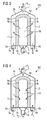
- FIG. 1 shows a longitudinal section through a first device 1 for the condensation of water from water vapor or a water vapor-containing gas in the condensation cycle.
- the first device 1 comprises a container 2 made of stainless steel, which has a circular circumference, a bottom 2a in the form of a flat bottom plate and a top 2b in the form of a conical finish.
- a first opening 3 In the bottom 2a of the container 2 are centrally located a first opening 3 and on a radius around this group a plurality of third openings 5a, 5b, wherein in this view, only two third openings can be seen.
- a first connecting line 6 connects.
- the third openings 5a, 5b are followed by third connection lines 8a, 8b.
- a second opening 4 is centrally formed, to which a second connecting line 7 connects.
- the container 2 has a longitudinal axis, wherein the longitudinal axis extends through the centers of the first opening 3 and the second opening 4.
- a heat transfer zone 9 is arranged, which divides the interior of the container 2 into a first zone 10 and a second zone 11.
- the first opening 3 thus opens into the first zone 10, while the second opening 4 and the third openings 5a, 5b open into the second zone 11.
- the heat transfer zone 9 extends from the bottom 2a of the container 2 tubular in the interior of the container 2 in the direction of the second opening 4 and ends at its the bottom 2a of the container 2 end facing away in an insulating plate 9d.
- the insulation plate 9d formed from fused alumina.
- a first separating layer 9a and a second separating layer 9b are arranged, each in the form of a tube made of stainless steel mesh, and a bulk material layer 9c arranged and fixed in the annular gap between them.
- the bulk material layer 9c is formed of AlN.
- a condensation cycle is performed first.
- a first process gas P 1 in the form of water vapor or water vapor-containing gas is introduced via the first connecting line 6 through the first opening 3 into the first zone 10 of the container 2.
- the first process gas P 1 is transferred through the tubular, flow-through region of the heat transfer zone 9 into the second zone 11 (indicated by arrows). This is followed by a cooling of the first process gas P 1 and a condensation of water W.
- the condensed water W flows in accordance with gravity in the direction of the bottom 2a of the container 2 and through the third openings 5a, 5b of Container 2 in the third connecting lines 8a, 8b derived.
- an unillustrated control system in the form of, for example, webs, gutters or the like can be arranged, which reliably derive the condensed water W into the third openings 5a, 5b.
- the condensed water W can now, for example, as feed water, immediately or after a Quality control and treatment was subjected, fed to an industrial process for further use or recycled.
- the cooler compared to the first process gas P 1 gaseous remainder R P1 of the first process gas P 1 is discharged through the second opening 4 of the container 2, for example to the environment.
- FIG. 2 shows the same longitudinal section through the first device according to FIG. 1 , but in the blowing cycle. Identical reference signs denote the same elements.
- a second process gas P 2 in the form of cooling air via the second connecting line 7 and the second opening 4 in the second zone 11 of the container 2 is initiated.
- the third openings 5a, 5b are closed by means of a respective valve not shown separately.
- the second process gas P 2 is transferred through the tubular, flow-through region of the heat transfer zone 9, which has previously been heated by means of the first process gas P 1 , into the first zone 10 of the container 2 (indicated by arrows). In this case, a cooling of the heat transfer zone 9 and a heating of the second process gas P 2 .
- the heated second process gas P 2 ' is discharged through the first opening 3 of the container 2 and the first connecting line 6.
- the condensation cycle (see FIG. 1 ) and the blowing cycle (see FIG. 2 ) are now performed alternately repeatedly on the device 1. Before the start of a further condensation cycle, the third openings 5a, 5b are to be released again, so that it can flow through this condensed water W.
- FIG. 3 shows a longitudinal section through a second device 100 for the condensation of water from water vapor or a water vapor-containing gas in the condensation cycle, similar to the first device 1 according to FIG. 1 is constructed.
- Like reference numerals denote like elements.
- a heat transfer zone 9 ' is arranged, which divides the interior of the container 2 into a first zone 10 and a second zone 11.
- the first opening 3 thus opens into the first zone 10, while the second opening 4 and the third openings 5a, 5b open into the second zone 11.
- the heat transfer zone 9 ' extends from the bottom 2a of the container 2 tubular in the interior of the container 2 in the direction of the second opening 4 and ends at its the bottom 2a of the container 2 opposite end in the form of a dome 9e.
- the heat transfer zone 9 ' is a total flow through and equipped with a first separation layer 9a and a second separation layer 9b, depending in the form of a dome made of stainless steel mesh. Arranged and fixed between these is a bulk material layer 9c made of graphite-filled plastic.
- FIG. 4 shows the same longitudinal section through the second device 100 according to FIG. 3 , but in the blowing cycle.
- a second process gas P 2 in the form of cooling air via the second connecting line 7 and the second opening 4 in the second zone 11 of the container 2 is initiated. Furthermore, the second process gas P 2 in the form of cooling air are also introduced via the third connecting lines 8a, 8b and the third openings 5a, 5b in the second zone 11 of the container 2, to generate a back pressure and to prevent escape of the second process gas P 2 through the third openings 5a, 5b.
- the second process gas P 2 is transferred through the previously heated by means of the first process gas P 1 heat transfer zone 9 'through the first zone 10 of the container 2 (indicated by arrows). In this case, a cooling of the heat transfer zone 9 'and a heating of the second process gas P 2 .
- the heated second process gas P 2 ' is discharged through the first opening 3 of the container 2 and the first connecting line 6.
- the condensation cycle (see FIG. 3 ) and the blowing cycle (see FIG. 4 ) are now performed alternately repeatedly on the device 100. Before the start of a further condensation cycle, the third openings 5a, 5b are to be released again so that water W flowing through them can flow away.
- the arrangement of the first, second and third openings on the container as well as the shape and design of the heat transfer zone there are a variety of other design options that can be alternatively selected by an expert without inventive step.
- a container may not only be in an upright position, as in FIGS FIGS. 1 to 4 in this case, the at least one third opening is arranged at the lowest point of the circular circumference and the heat transfer zone is correspondingly redesigned.
Landscapes
- Engineering & Computer Science (AREA)
- Chemical & Material Sciences (AREA)
- Chemical Kinetics & Catalysis (AREA)
- Automation & Control Theory (AREA)
- Oil, Petroleum & Natural Gas (AREA)
- General Chemical & Material Sciences (AREA)
- Analytical Chemistry (AREA)
- Environmental & Geological Engineering (AREA)
- Health & Medical Sciences (AREA)
- Life Sciences & Earth Sciences (AREA)
- Hydrology & Water Resources (AREA)
- Public Health (AREA)
- Water Supply & Treatment (AREA)
- Vaporization, Distillation, Condensation, Sublimation, And Cold Traps (AREA)
- Heat-Exchange Devices With Radiators And Conduit Assemblies (AREA)
Description
- Die Erfindung betrifft eine Vorrichtung und ein Verfahren zur Kondensation von Wasser aus Wasserdampf oder aus einem Wasserdampf enthaltenden Gas.
- Es ist bereits bekannt, Wasser aus Wasserdampf oder einem Wasserdampf enthaltenden Gas durch Abkühlen des Wasserdampfs oder Wasserdampf enthaltenden Gases zu kondensieren und abzuscheiden, indem zum Abkühlen Kühlwasser verwendet wird. Bei diesem ersten bekannten Verfahren wird Wärme an das Kühlwasser abgeführt und dieses anschließend in einem Kühlturm rückgekühlt, wobei beträchtliche Mengen an Wasser durch Verdunstung verloren gehen.
- Alternativ ist es bereits bekannt, eine Kondensation von Wasser aus Wasserdampf oder einem Wasserdampf enthaltendem Gas in einem geschlossenen Kreislauf durchzuführen, wobei der Wasserdampf oder das Wasserdampf enthaltende Gas mittels eines gasförmigen Kühlmediums, wie beispielsweise Kühlluft, gekühlt wird. Das kondensierte Wasser wird aufgefangen und einer weiteren Nutzung zugeführt. Allerdings ist dieses zweite Verfahren mit erheblich höheren Betriebskosten verbunden als das erste Verfahren
- Sowohl bei der Durchführung des ersten wie auch des zweiten Verfahrens gehen beträchtliche Mengen an thermischer Energie ungenutzt verloren.
- Die
DE 44 35 642 A1 offenbart eine Vorrichtung zur Kondensation von Wasser aus einem Wasserdampf enthaltenden Gas mit einem Behälter, dessen Inneres durch eine Wärmeübergangszone aus Kohle in einen ersten Bereich und einen zweiten Bereich unterteilt ist, und wobei eine erste Öffnung für den Einlas von feuchtem Gas in den ersten Bereich mündet und eine zweite sowie eine dritte Öffnung in den zweiten Bereich münden und der Abfuhr von getrocknetem Gas und Kondensat dienen. Bei der Trocknung wird durch Drehung der Kohlenschicht die Zentrifugalkraft für die Abscheidung des Kondensats genutzt. - Es ist daher Aufgabe der Erfindung, eine Vorrichtung und ein Verfahren zur Kondensation von Wasser bereitzustellen, die eine wirtschaftlichere Nutzung der thermischen Energie und des Wassers in Wasserdampf oder Wasserdampf enthaltendem Gas ermöglichen.
- Die Aufgabe wird für die Vorrichtung zur Kondensation von Wasser aus Wasserdampf oder aus einem Wasserdampf enthaltenden Gas gelöst mit den Merkmalen des Anspruchs 1.
- Unter einem durchströmbaren Bereich einer Wärmeübergangszone wird dabei verstanden, dass die Wärmeübergangszone dort Kanäle und/oder eine offene Porosität aufweist und somit eine Gas- und/oder Wasserdampfdurchlässigkeit vorliegt.
- Die Aufgabe wird für das Verfahren zur Kondensation von Wasser aus Wasserdampf oder aus einem Wasserdampf enthaltenden Gas gelöst, indem unter Verwendung der erfindungsgemäßen Vorrichtung abwechselnd folgende Zyklen erfolgen:
- Durchführen eines Kondensationszyklus durch
- Einleiten eines ersten Prozessgases in Form von Wasserdampf oder eines Wasserdampf enthaltenden Gases über die mindestens eine erste Öffnung in die erste Zone des Behälters;
- Überführen des ersten Prozessgases durch die Wärmeübergangszone hindurch in die zweite Zone unter Kondensation von Wasser und Erwärmung der Wärmeübergangszone;
- Ableiten des kondensierten Wassers durch die mindestens eine dritte Öffnung des Behälters und des gasförmigen Rests des ersten Prozessgases durch die mindestens eine zweite Öffnung des Behälters; und
- Durchführen eines Anblaszyklus durch
- Einleiten eines zweiten Prozessgases in Form von Kühlgas über mindestens die mindestens eine zweite Öffnung in die zweite Zone des Behälters;
- Überführen des zweiten Prozessgases durch die Wärmeübergangszone hindurch in die erste Zone unter Abkühlung der Wärmeübergangszone;
- Ableiten des erwärmten zweiten Prozessgases durch die mindestens eine erste Öffnung des Behälters.
- Die erfindungsgemäße Vorrichtung weist eine einfache Bauart auf und ist somit kostengünstig herstellbar. Die Vorrichtung und das erfindungsgemäße Verfahren ermöglichen eine wesentlich bessere Ausnutzung der thermischen Energie und des Wassers, welche in Wasserdampf oder Wasserdampf enthaltendem Gas gespeichert sind, als dies mit bisher bekannten Verfahren und Vorrichtungen möglich war. Zudem sind die Betriebskosten der erfindungsgemäßen Vorrichtung und des erfindungsgemäßen Verfahren gegenüber denen von bisher eingesetzten Vorrichtungen und Verfahren deutlich vermindert.
- Das kondensierte Wasser ist im Normalfall reines Wasser oder nahezu reines Wasser und kann meist unmittelbar einem industriellen Prozess, beispielsweise als Speisewasser, zugeführt bzw. wieder zugeführt werden. Das kondensierte Wasser kann aber, falls erforderlich, alternativ auch einer Qualitätskontrolle und/oder einer Aufbereitung zugeführt werden. Dies ist insbesondere dann von Vorteil, wenn ein bestimmter Reinheitsgrad, pH-Wert und dergleichen für die weitere Nutzung des kondensierten Wassers von Bedeutung ist.
- Bevorzugte Ausgestaltungen der Vorrichtung und des Verfahrens sind in den Unteransprüchen angegeben und werden nachfolgend im Detail erläutert.
- Für die Vorrichtung hat es sich bewährt, wenn der Behälter eine Längsachse aufweist und die Längsachse sich durch den Mittelpunkt oder Schwerpunkt der mindestens einen ersten Öffnung und der mindestens einen zweiten Öffnung erstreckt. Weiterhin hat es sich als vorteilhaft erwiesen, den Behälter, mit einem rotationssymmetrischen Umfang auszubilden, wobei die Längsachse als Rotationsachse dient. Besonders bevorzugt ist ein Behälter mit einem kreisförmigen Umfang ausgebildet, der auf seiner Unterseite mit einer ebenen, gewölbten oder kegelförmigen Bodenplatte und auf seiner Oberseite mit einem hauben- oder kegelförmigen Abschluss versehen ist. Der Behälter ist bevorzugt aus Stahl ausgebildet.
- Es hat sich weiterhin bewährt, die mindestens eine erste Öffnung und die mindestens eine dritte Öffnung im Bereich einer Unterseite des Behälters anzuordnen und weiterhin die mindestens eine zweite Öffnung im Bereich einer Oberseite des Behälters anzuordnen. Die mindestens eine dritte Öffnung ist dabei besonders bevorzugt an der tiefsten Stelle des Behälters, wie beispielsweise in der Bodenplatte des Behälters, angeordnet. So kann kondensiertes Wasser, das sich dort aufgrund der Schwerkraft sammelt, unmittelbar und ohne weitere Hilfsmittel, wie Pumpen oder dergleichen, abfließen.
- Insbesondere hat sich eine Anordnung der mindestens einen ersten Öffnung, welche unter anderem zum Einleiten von Wasserdampf oder Wasserdampf enthaltendem Gas dient, im Zentrum der Bodenplatte des Behälters bewährt. Die mindestens eine dritte Öffnung wird in Folge bevorzugt auf einem Radius um die zentral angeordnete, mindestens eine erste Öffnung herum angeordnet. Die mindestens eine zweite Öffnung bildet bevorzugt das Ende des hauben- oder kegelförmigen Abschlusses an einer Oberseite des Behälters. Dabei ist die mindestens eine erste Öffnung vorteilhafter Weise fluchtend zur mindestens einen zweiten Öffnung angeordnet.
- Aber auch andere Anordnungen der mindestens einen ersten, zweiten und dritten Öffnungen sind je nach Bauart des Behälters verwendbar. So kann ein langgestreckter Behälter auch liegend anstatt aufrecht stehend eingesetzt werden. In einem solchen Fall ist die mindestens eine erste Öffnung bevorzugt an einer Seite und die mindestens eine zweite Öffnung bevorzugt auf der dazu gegenüber liegenden Seite angeordnet. Die mindestens eine dritte Öffnung wird bevorzugt im Bereich der Behältermitte an der untersten Stelle des Behälters angeordnet.
- Weiterhin hat es sich bewährt, wenn ein Leitsystem in Form von beispielsweise Stegen, Rinnen oder dergleichen im Bereich der Unterseite des Behälters angeordnet ist, die kondensierendes Wasser zuverlässig in Richtung der mindestens einen dritten Öffnungen ableiten.
- Die Wärmeübergangszone erstreckt sich vorzugsweise ausgehend von dem Bereich des Behälters, in welchem sich die mindestens eine erste Öffnung befindet, wie beispielsweise eine Unterseite, insbesondere Bodenplatte, des Behälters, rohrförmig in Richtung der mindestens einen zweiten Öffnung. Dabei beherbergt die Wärmeübergangzone die erste Zone und bildet beispielsweise ein haubenförmiges Gebilde über der mindestens einen ersten Öffnung. Das der mindestens einen ersten Öffnung im Behälter abgewandte Ende der Wärmeübergangszone verschließt den rohrförmigen Bereich und ist dabei entweder eben, kegel- oder kuppelförmig ausgebildet.
- Bevorzugt ist der rohrförmige Bereich der Wärmeübergangszone durchströmbar ausgebildet. Das den rohrförmigen Bereich verschließende Ende kann dabei ebenfalls durchströmbar ausgebildet oder aber undurchlässig für Wasserdampf oder das Wasserdampf enthaltende Gas ausgeführt sein.
- Ein ebenes Ende wird insbesondere durch eine Isolierplatte gebildet, welche für den Wasserdampf oder das Wasserdampf enthaltende Gas undurchlässig ist. Eine solche Isolierplatte ist bevorzugt aus einem Material mit geringer Wärmeleitfähigkeit gebildet, das insbesondere im Temperaturbereich bis 300°C eine Wärmeleitfähigkeit von maximal 20 W(mK)-1 aufweist, wie beispielsweise Schmelzkorund.
- Der durchströmbare Bereich der Wärmeübergangszone umfasst insbesondere mindestens eine Schüttgutschicht und/oder mindestens eine Faserschicht und/oder mindestens eine textile Schicht und/oder mindestens eine Gitterschicht und/oder mindestens eine Netzschicht und/oder mindestens ein Lochblech.
- Zur Ausbildung einer Schüttgutschicht hat sich insbesondere keramisches und/oder polymeres Material als geeignet erwiesen, wie beispielsweise AlN, Graphit-gefüllte Kunststoffe und dergleichen. Geeignete Fasern zur Ausbildung einer Faserschicht sind beispielsweise aus Metall, insbesondere Stahl gebildet. Gitter- und Netzschichten sind bevorzugt aus Metalldraht gebildet, insbesondere aus Stahl. Eine Kombination von Schüttgut und Gitter- oder Netzschichten, von Schüttgut und Lochblech, von Schüttgut, Fasern und Gitter- und Netzschichten oder von Schüttgut, Fasern und Lochblech ist besonders bevorzugt.
- Erfindungsgemäβ weist der durchströmbare Bereich der Wärmeübergangszone zumindest teilweise Materialien auf, die im Temperaturbereich bis 300°C eine Wärmeleitfähigkeit von grö-βer als 20 W(mK)-1, insbesondere größer als 20 W(mK)-1, aufweisen.
- Es hat sich bewährt, den durchströmbaren Bereich der Wärmeübergangszone auf ihrer der ersten Zone zugewandten Oberfläche zumindest teilweise mit einer durchströmbaren ersten Trennschicht und/oder auf ihrer der zweiten Zone zugewandten Oberfläche zumindest teilweise mit einer durchströmbaren zweiten Trennschicht auszustatten.
- Bevorzugt wird eine Wärmeübergangszone gebildet, indem konzentrische Röhren aus Gitter, Netz oder Lochblech gebildet werden, welche jeweils eine Trennschicht bereitstellen. Zwischen den Röhren bildet sich ein Ringspalt aus, in dem eine Schüttgutschicht und/oder Faserschicht durch Einfüllen von Schüttgut und/oder Fasern gebildet wird. Die Maschen der Gitter oder Netze bzw. die Löcher der Lochbleche sind dabei derart zu dimensionieren, dass das eingefüllte Schüttgut und/oder die Fasern nicht durch diese hindurch gelangen können.
- Unter einer textilen Schicht wird hier ein einlagiges oder mehrlagiges Gewirk, Gestrick, Gewebe oder Vlies verstanden. Dieses kann aus keramischen Fasern bzw. Fäden und/oder Glasfasern und/oder Metallfasern und/oder Kunststofffasern gebildet sein.
- Weiterhin ist es von Vorteil, mehrere unterschiedlich ausgestaltete durchströmbare Bereiche ausgehend von der ersten Öffnung entlang der ersten Zone und/oder mehrere unterschiedlich ausgestaltete durchströmbare Schichten ausgehend von der ersten Zone in Richtung der zweiten Zone aufeinander folgend in der Wärmeübergangszone anzuordnen. Die unterschiedlichen durchströmbaren Bereiche und/oder Schichten unterschieden sich insbesondere hinsichtlich ihrer Porosität und/oder Wärmeleitfähigkeit und/oder Schüttdichte und/oder Korngrößenoder Faserlängenverteilung und dergleichen.
- Bei dem Verfahren hat es sich als vorteilhaft erwiesen, im Anblaszyklus vor dem Einleiten des zweiten Prozessgases die mindestens eine dritte Öffnung zu schließen und nach Durchführung des Anblaszyklus die mindestens eine dritte Öffnung wieder zu freizugeben. Durch das Schließen der mindestens einen dritten Öffnung wird zuverlässig verhindert, dass das zweite Prozessgas zumindest teilweise ungenutzt durch die mindestens eine dritte Öffnung entweicht.
- Alternativ zu einem Schließen der mindestens einen dritten Öffnung kann ein Entweichen von zweitem Prozessgas durch die mindestens eine dritte Öffnung auch verhindert werden, wenn im Bereich der mindestens einen dritten Öffnung ein Gegendruck aufgebaut wird. Dies kann beispielsweise dadurch erfolgen, dass das zweite Prozessgas nicht nur über die mindestens eine zweite Öffnung, sondern auch über die mindestens eine dritte Öffnung in den Behälter eingeleitet wird.
- Die optimale Taktung von Kondensations- und Anblaszyklus hängt dabei von der geometrischen Ausgestaltung der Vorrichtung, der Materialwahl zur Ausbildung der Vorrichtung und weiterhin den konkreten Prozessparametern, wie der Menge und Temperatur des ersten Prozessgases, der Menge an kondensierendem Wasser, der Temperatur des zweiten Prozessgases, usw. ab und ist experimentell in einfacher Weise für eine jede Vorrichtung zu bestimmen.
- Die FIGen 1 bis 4 sollen mögliche Vorrichtungen und mögliche Verfahren beispielhaft erläutern. So zeigt:
- FIG 1
- einen Längsschnitt durch eine erste Vorrichtung im Kondensationszyklus;
- FIG 2
- einen Längsschnitt durch die erste Vorrichtung gemäß
FIG 1 im Anblaszyklus. - FIG 3
- einen Längsschnitt durch eine zweite Vorrichtung im Kondensationszyklus; und
- FIG 4
- einen Längsschnitt durch die zweite Vorrichtungsgemäß
FIG 3 im Anblaszyklus. -
FIG 1 zeigt einen Längsschnitt durch eine erste Vorrichtung 1 zur Kondensation von Wasser aus Wasserdampf oder einem Wasserdampf enthaltenden Gas im Kondensationszyklus. Die erste Vorrichtung 1 weist einen Behälter 2 aus Edelstahl auf, welcher einen kreisförmigen Umfang, eine Unterseite 2a in Form einer ebenen Bodenplatte und eine Oberseite 2b in Form eines kegelförmigen Abschlusses aufweist. In der Unterseite 2a des Behälters 2 befinden sich mittig eine erste Öffnung 3 und auf einem Radius um diese gruppieren mehrere dritte Öffnungen 5a, 5b, wobei in dieser Ansicht lediglich zwei dritte Öffnungen erkennbar sind. An die erste Öffnung 3 schließt sich eine erste Anschlussleitung 6 an. An die dritten Öffnungen 5a, 5b schließen sich dritte Anschlussleitungen 8a, 8b an. In der Oberseite 2b des Behälters 2 ist mittig eine zweite Öffnung 4 ausgebildet, an die sich eine zweite Anschlussleitung 7 anschließt. Der Behälter 2 weist eine Längsachse auf, wobei die Längsachse sich durch die Mittelpunkte der ersten Öffnung 3 und der zweiten Öffnung 4 erstreckt. - Im Inneren des Behälters 2 ist eine Wärmeübergangszone 9 angeordnet, welche das Innere des Behälters 2 in eine erste Zone 10 und eine zweite Zone 11 unterteilt. Die erste Öffnung 3 mündet somit in die erste Zone 10, während die zweite Öffnung 4 sowie die dritten Öffnungen 5a, 5b in die zweite Zone 11 münden. Die Wärmeübergangszone 9 erstreckt sich ausgehend von der Unterseite 2a des Behälters 2 rohrförmig im Inneren des Behälters 2 in Richtung der zweiten Öffnung 4 und endet an ihrem der Unterseite 2a des Behälters 2 abgewandten Ende in einer Isolationsplatte 9d. Die Isolationsplatte 9d aus Schmelzkorund gebildet. Im rohrförmigen Bereich der Wärmeübergangszone 9 sind eine erste Trennschicht 9a und eine zweite Trennschicht 9b angeordnet, je in Form einer Röhre aus Edelstahlgitter, sowie eine im Ringspalt zwischen diesen angeordnete und fixierte Schüttgutschicht 9c. Die Schüttgutschicht 9c ist aus AlN ausgebildet.
- Bei dem Verfahren zur Kondensation von Wasser aus Wasserdampf oder Wasserdampf enthaltendem Gas unter Verwendung der Vorrichtung 1 erfolgt zuerst ein Kondensationszyklus. Dabei wird ein erstes Prozessgas P1 in Form von Wasserdampf oder Wasserdampf enthaltendem Gas über die erste Anschlussleitung 6 durch die erste Öffnung 3 in die erste Zone 10 des Behälters 2 eingeleitet. Anschließend wird das erste Prozessgas P1 durch den rohrförmigen, durchströmbaren Bereich der Wärmeübergangszone 9 hindurch in die zweite Zone 11 überführt (gekennzeichnet durch Pfeile). Dabei erfolgen eine Abkühlung des ersten Prozessgases P1 und eine Kondensation von Wasser W. Gleichzeitig erfolgt eine Erwärmung der Wärmeübergangszone 9. Das kondensierte Wasser W fließt entsprechend der Schwerkraft in Richtung der Unterseite 2a des Behälters 2 und wird durch die dritten Öffnungen 5a, 5b des Behälters 2 in die dritten Anschlussleitungen 8a, 8b abgeleitet. Hier kann weiterhin ein nicht dargestelltes Leitsystem in Form von beispielsweise Stegen, Rinnen oder dergleichen angeordnet sein, die das kondensierte Wasser W zuverlässig in die dritten Öffnungen 5a, 5b ableiten. Das kondensierte Wasser W kann nun, beispielsweise als Speisewasser, unmittelbar oder nachdem es einer Qualitätskontrolle und Aufbereitung unterzogen wurde, einem industriellen Prozess zur weiteren Nutzung zugeführt oder wieder zugeführt werden.
- Der im Vergleich zum ersten Prozessgas P1 kühlere gasförmige Rest RP1 des ersten Prozessgases P1 wird durch die zweite Öffnung 4 des Behälters 2 abgeführt, beispielsweise an die Umgebung.
-
FIG 2 zeigt den gleichen Längsschnitt durch die erste Vorrichtung gemäßFIG 1 , jedoch im Anblaszyklus. Gleiche Bezugszeichen kennzeichnen dabei gleiche Elemente. Im Anblaszyklus wird ein zweites Prozessgas P2 in Form von Kühlluft über die zweite Anschlussleitung 7 und die zweite Öffnung 4 in die zweite Zone 11 des Behälters 2 eingeleitet. Um ein Entweichen des zweiten Prozessgases P2 durch die dritten Öffnungen 5a, 5b während des Einleitens des zweiten Prozessgases P2 in die zweite Zone 11 des Behälters 2 zu verhindern, werden die dritten Öffnungen 5a, 5b mittels jeweils eines nicht gesondert dargestellten Ventils verschlossen. Das zweite Prozessgas P2 wird durch den rohrförmigen, durchströmbaren Bereich der Wärmeübergangszone 9, welche zuvor mittels des ersten Prozessgases P1 erwärmt worden ist, hindurch in die erste Zone 10 des Behälters 2 überführt (gekennzeichnet durch Pfeile). Dabei erfolgen eine Abkühlung der Wärmeübergangszone 9 und eine Erwärmung des zweiten Prozessgases P2. - Schließlich wird das erwärmte zweite Prozessgas P2' durch die erste Öffnung 3 des Behälters 2 und die erste Anschlussleitung 6 abgeleitet. Das erwärmte zweite Prozessgas P2' kann nun einem industriellen Prozess zur weiteren Nutzung zugeführt werden.
- Der Kondensationszyklus (siehe
FIG 1 ) und der Anblaszyklus (sieheFIG 2 ) werden nun abwechselnd wiederholt an der Vorrichtung 1 durchgeführt. Vor Beginn eines weiteren Kondensationszyklus sind die dritten Öffnungen 5a, 5b wieder freizugeben, damit durch diese kondensiertes Wasser W abfließen kann. -
FIG 3 zeigt einen Längsschnitt durch eine zweite Vorrichtung 100 zur Kondensation von Wasser aus Wasserdampf oder einem Wasserdampf enthaltenden Gas im Kondensationszyklus, die ähnlich wie die erste Vorrichtung 1 gemäßFIG 1 aufgebaut ist. Gleiche Bezugszeichen kennzeichnen gleiche Elemente. - Im Inneren des Behälters 2 ist eine Wärmeübergangszone 9' angeordnet, welche das Innere des Behälters 2 in eine erste Zone 10 und eine zweite Zone 11 unterteilt. Die erste Öffnung 3 mündet somit in die erste Zone 10, während die zweite Öffnung 4 sowie die dritten Öffnungen 5a, 5b in die zweite Zone 11 münden. Die Wärmeübergangszone 9' erstreckt sich ausgehend von der Unterseite 2a des Behälters 2 rohrförmig im Inneren des Behälters 2 in Richtung der zweiten Öffnung 4 und endet an ihrem der Unterseite 2a des Behälters 2 abgewandten Ende in Form einer Kuppel 9e. Die Wärmeübergangszone 9' ist insgesamt durchströmbar und mit einer ersten Trennschicht 9a und einer zweiten Trennschicht 9b ausgestattet, je in Form einer Kuppel aus Edelstahlgitter. Zwischen diesen angeordnet und fixiert befindet sich eine Schüttgutschicht 9c aus Graphitgefülltem Kunststoff.
- Bei dem Verfahren zur Kondensation von Wasser aus Wasserdampf oder Wasserdampf enthaltendem Gas mittels der Vorrichtung 100 erfolgt zunächst ein Kondensationszyklus, wie bereits zu
FIG 1 beschrieben. -
FIG 4 zeigt den gleichen Längsschnitt durch die zweite Vorrichtung 100 gemäßFIG 3 , jedoch im Anblaszyklus. - Gleiche Bezugszeichen kennzeichnen dabei gleiche Elemente. Im Anblaszyklus wird ein zweites Prozessgas P2 in Form von Kühlluft über die zweite Anschlussleitung 7 und die zweite Öffnung 4 in die zweite Zone 11 des Behälters 2 eingeleitet. Weiterhin wird das zweite Prozessgas P2 in Form von Kühlluft auch über die dritten Anschlussleitungen 8a, 8b und die dritten Öffnungen 5a, 5b in die zweite Zone 11 des Behälters 2 eingeleitet, um einen Gegendruck zu erzeugen und ein Entweichen des zweiten Prozessgases P2 durch die dritten Öffnungen 5a, 5b zu verhindern. Das zweite Prozessgas P2 wird durch die zuvor mittels des ersten Prozessgases P1 erwärmte Wärmeübergangszone 9' hindurch in die erste Zone 10 des Behälters 2 überführt (gekennzeichnet durch Pfeile). Dabei erfolgen eine Abkühlung der Wärmeübergangszone 9' und eine Erwärmung des zweiten Prozessgases P2.
- Schließlich wird das erwärmte zweite Prozessgas P2' durch die erste Öffnung 3 des Behälters 2 und die erste Anschlussleitung 6 abgeleitet. Das erwärmte zweite Prozessgas P2' kann nun einem industriellen Prozess zur weiteren Nutzung zugeführt werden.
- Der Kondensationszyklus (siehe
FIG 3 ) und der Anblaszyklus (sieheFIG 4 ) werden nun abwechselnd wiederholt an der Vorrichtung 100 durchgeführt. Vor Beginn eines weiteren Kondensationszyklus sind die dritten Öffnungen 5a, 5b wieder freizugeben, damit durch diese kondensierendes Wasser W abfließen kann. - Im Hinblick auf die in den beispielhaft gewählten Figuren gezeigte Ausgestaltung des Behälters, die Anordnung der ersten, zweiten und dritten Öffnungen am Behälter sowie die Form und Ausgestaltung der Wärmeübergangszone bestehen eine Vielzahl weiterer Gestaltungsmöglichkeiten, die ohne erfinderisches Zutun von einem Fachmann alternativ gewählt werden können. Beispielsweise kann ein Behälter nicht nur in aufrecht stehender Position, wie in den
Figuren 1 bis 4 dargestellt, sondern auch liegend betrieben werden, wobei die mindestens eine dritte Öffnung in diesem Fall an der tiefsten Stelle des kreisförmigen Umfangs angeordnet wird und die Wärmeübergangszone entsprechend umgestaltet wird.
Claims (9)
- Vorrichtung (1, 100) zur Kondensation von Wasser aus einem ersten Prozessgas in Form von Wasserdampf oder einem Wasserdampf enthaltenden Gas, umfassend- einen Behälter (2) mit mindestens einer ersten Öffnung (3), mindestens einer zweiten Öffnung (4) und mindestens einer dritten Öffnung (5a, 5b), und- eine in einem Inneren des Behälters (2) angeordnete Wärmeübergangszone (9, 9'), welche mindestens eine Schüttgutschicht (9c) und/oder mindestens eine Faserschicht und/oder mindestens eine textile Schicht und/oder mindestens eine Gitterschicht und/oder mindestens eine Netzschicht und/oder mindestens ein Lochblech umfasst,- wobei das Innere des Behälters (2) mittels der Wärmeübergangszone (9, 9') in eine erste Zone (10) und eine zweite Zone (11) unterteilt ist, und wobei die mindestens eine erste Öffnung (3) in die erste Zone (10) mündet und die mindestens eine zweite Öffnung (4) sowie die mindestens eine dritte Öffnung (5a, 5b) in die zweite Zone (11) münden und- wobei die Wärmeübergangszone (9, 9') zumindest bereichsweise eine offene Porosität und/oder Kanäle aufweist, welche von dem ersten Prozessgas von der ersten Zone (10) in Richtung der zweiten Zone (11) durchströmbar ist und von einem zweiten Prozessgas in Form von Kühlgas in umgekehrter Richtung durchströmbar ist/sind und- wobei ein durchströmbarer Bereich der Wärmeübergangszone (9,9') zumindest teilweise Materialien aufweist, die in einem Temperaturbereich bis 300°C eine Wärmeleitfähigkeit von größer als 20 W(mK)-1 aufweisen.
- Vorrichtung nach Anspruch 1, wobei der Behälter (2) eine Längsachse aufweist und wobei die Längsachse sich durch einen Mittelpunkt oder Schwerpunkt der mindestens einen ersten Öffnung (3) und der mindestens einen zweiten Öffnung (4) erstreckt.
- Vorrichtung nach Anspruch 1 oder Anspruch 2, wobei die mindestens eine erste Öffnung (3) und die mindestens eine dritte Öffnung (5a, 5b) im Bereich einer Unterseite (2a) des Behälters (2) angeordnet sind und weiterhin die mindestens eine zweite Öffnung (4) im Bereich einer Oberseite (2b) des Behälters (2) angeordnet ist.
- Vorrichtung nach einem der Ansprüche 1 bis 3, wobei die Wärmeübergangszone (9, 9') sich ausgehend von der Unterseite (2a) des Behälters (2) rohrförmig in Richtung der mindestens einen zweiten Öffnung (4) erstreckt.
- Vorrichtung nach einem der Ansprüche 1 bis 4, wobei die Wärmeübergangszone (9, 9') mindestens eine Schüttgutschicht (9c) und/oder mindestens eine Faserschicht umfasst und wobei die durchströmbaren Bereiche der Wärmeübergangszone (9, 9') auf ihrer der ersten Zone (10) zugewandten Oberfläche und/oder auf ihrer der zweiten Zone zugewandten Oberfläche mit einer Trennschicht (9a, 9b) in Form einer Gitterschicht aus Metalldraht, einer Netzschicht aus Metalldraht oder einem Lochblech ausgebildet sind.
- Vorrichtung nach einem der Ansprüche 1 bis 5, wobei die Wärmeübergangszone (9) weiterhin eine Isolationsplatte (9d) umfasst, welche für den Wasserdampf oder das Wasserdampf enthaltende Gas undurchlässig ist.
- Verfahren zur Kondensation von Wasser aus Wasserdampf oder aus einem Wasserdampf enthaltenden Gas, mittels einer Vorrichtung (1, 100) nach einem der Ansprüche 1 bis 6, mit folgenden abwechselnd durchgeführten Zyklen:Durchführen eines Kondensationszyklus durch Einleiten des ersten Prozessgases in Form von Wasserdampf oder eines Wasserdampf enthaltenden Gases über die mindestens eine erste Öffnung (3) in die erste Zone (10);überführen des ersten Prozessgases durch die Wärmeübergangszone (9, 9') hindurch in die zweite Zone (11) unter Kondensation von Wasser und Erwärmung der Wärmeübergangszone (9, 9');Ableiten des kondensierten Wassers durch die mindestens eine dritte Öffnung (5a, 5b) des Behälters (2) und des gasförmigen Rests des Prozessgases durch die mindestens eine zweite Öffnung (4); undDurchführen eines Anblaszyklus durch Einleiten eines zweiten Prozessgases in Form von Kühlgas über mindestens die mindestens eine zweite Öffnung (4) in die zweite Zone (11);Überführen des zweiten Prozessgases durch die Wärmeübergangszone (9) hindurch in die erste Zone (10) unter Abkühlung der Wärmeübergangszone (9); undAbleiten des erwärmten zweiten Prozessgases durch die mindestens eine erste Öffnung (3).
- Verfahren nach Anspruch 7, wobei im Anblaszyklus vor dem Einleiten des zweiten Prozessgases ein Schließen der mindestens einen dritten Öffnung (5a, 5b) erfolgt und nach Durchführung des Anblaszyklus die mindestens eine dritte Öffnung (5a, 5b) wieder freigegeben wird.
- Verfahren nach Anspruch 7, wobei im Anblaszyklus das zweite Prozessgases weiterhin über die mindestens eine dritte Öffnung (5a, 5b) in die zweite Zone (11) eingeleitet wird.
Applications Claiming Priority (2)
| Application Number | Priority Date | Filing Date | Title |
|---|---|---|---|
| DE102009017840A DE102009017840A1 (de) | 2009-04-17 | 2009-04-17 | Vorrichtung und Verfahren zur Kondensation von Wasser |
| PCT/EP2010/054758 WO2010119008A1 (de) | 2009-04-17 | 2010-04-12 | Vorrichtung und verfahren zur kondensation von wasser |
Publications (2)
| Publication Number | Publication Date |
|---|---|
| EP2419195A1 EP2419195A1 (de) | 2012-02-22 |
| EP2419195B1 true EP2419195B1 (de) | 2013-06-05 |
Family
ID=42271867
Family Applications (1)
| Application Number | Title | Priority Date | Filing Date |
|---|---|---|---|
| EP10713223.5A Active EP2419195B1 (de) | 2009-04-17 | 2010-04-12 | Vorrichtung und verfahren zur kondensation von wasser |
Country Status (7)
| Country | Link |
|---|---|
| US (1) | US8657926B2 (de) |
| EP (1) | EP2419195B1 (de) |
| CN (1) | CN102458613A (de) |
| DE (1) | DE102009017840A1 (de) |
| ES (1) | ES2415159T3 (de) |
| RU (1) | RU2011146639A (de) |
| WO (1) | WO2010119008A1 (de) |
Families Citing this family (7)
| Publication number | Priority date | Publication date | Assignee | Title |
|---|---|---|---|---|
| CN103669479B (zh) * | 2012-09-25 | 2015-02-11 | 王万强 | 凝水塔 |
| CN102839714B (zh) * | 2012-09-26 | 2014-02-19 | 上海沃施园艺股份有限公司 | 一种雨水、雾水收集器 |
| US9587381B2 (en) | 2014-11-22 | 2017-03-07 | J. Glenn Turner, Jr. | System, and associated method, for recovering water from air |
| US11185792B2 (en) | 2014-11-22 | 2021-11-30 | J. Glenn Turner, Jr. | System, and associated method, for recovering water from air |
| CN104848198B (zh) * | 2015-05-20 | 2017-03-08 | 郑志强 | 重力分离式冷凝水自动收集器 |
| CN104895143B (zh) * | 2015-05-27 | 2016-08-17 | 国网山东省电力公司电力科学研究院 | 一种高效雾水收集装置与方法 |
| US10981108B2 (en) | 2017-09-15 | 2021-04-20 | Baker Hughes, A Ge Company, Llc | Moisture separation systems for downhole drilling systems |
Family Cites Families (13)
| Publication number | Priority date | Publication date | Assignee | Title |
|---|---|---|---|---|
| DE519618C (de) | 1928-09-29 | 1931-03-02 | Achille Knapen | Vorrichtung zur Gewinnung von Trink- und Gebrauchswasser aus der Luft |
| US4600416A (en) | 1985-02-08 | 1986-07-15 | La-Man Corporation | Air line vapor trap |
| US5002590A (en) | 1989-09-19 | 1991-03-26 | Bend Research, Inc. | Countercurrent dehydration by hollow fibers |
| DE4435642A1 (de) | 1993-10-08 | 1995-04-13 | Rolf Thelen | Filter-Zentrifuge |
| NL1000109C2 (nl) * | 1995-04-11 | 1996-04-16 | Hoek Mach Zuurstoff | Werkwijze voor het condenseren van een vluchtige stof uit een gasstroom en inrichting daarvoor. |
| SG104251A1 (en) * | 1998-01-26 | 2004-06-21 | Kankyo Co Ltd | Method and apparatus for dehumidifying air |
| DE19804682A1 (de) | 1998-02-06 | 1999-08-12 | Peter Weisshaar Gmbh Ing | Vorrichtung zur Durchführung eines kombinierten Kälte-/Membranabsorptionsverfahrens zur Trocknung von Luft und technischen Gasen |
| DE19849216A1 (de) | 1998-10-26 | 2000-04-27 | Andreas Noack | Verfahren und Vorrichtung zur Trennung von Fluidgemischen (Thermomembranverfahren) |
| JP2001070737A (ja) * | 1999-09-07 | 2001-03-21 | Daiwa Kogyo Kk | 溶剤回収装置と溶剤回収方法 |
| DE10107533A1 (de) | 2001-02-17 | 2002-08-29 | Friedrich Becker | Absorptionswärmepumpe mit Fasermatte und kontinuierlichem Wärmetausch |
| JP2002301302A (ja) * | 2001-04-05 | 2002-10-15 | Nkk Corp | 排ガス中に含まれる凝縮性物質の除去・回収方法および装置 |
| US7481074B2 (en) * | 2006-03-01 | 2009-01-27 | Air Products And Chemicals, Inc. | Self-contained distillation purifier/superheater for liquid-fill product container and delivery systems |
| US20100170499A1 (en) | 2006-08-08 | 2010-07-08 | Ewa Tech Ltd. | Method and apparatus for extracting water from atmospheric air and utilizing the same |
-
2009
- 2009-04-17 DE DE102009017840A patent/DE102009017840A1/de not_active Withdrawn
-
2010
- 2010-04-12 EP EP10713223.5A patent/EP2419195B1/de active Active
- 2010-04-12 CN CN2010800271412A patent/CN102458613A/zh active Pending
- 2010-04-12 RU RU2011146639/05A patent/RU2011146639A/ru not_active Application Discontinuation
- 2010-04-12 WO PCT/EP2010/054758 patent/WO2010119008A1/de not_active Ceased
- 2010-04-12 US US13/264,022 patent/US8657926B2/en not_active Expired - Fee Related
- 2010-04-12 ES ES10713223T patent/ES2415159T3/es active Active
Also Published As
| Publication number | Publication date |
|---|---|
| ES2415159T3 (es) | 2013-07-24 |
| RU2011146639A (ru) | 2013-05-27 |
| DE102009017840A1 (de) | 2010-10-28 |
| CN102458613A (zh) | 2012-05-16 |
| EP2419195A1 (de) | 2012-02-22 |
| US20120037343A1 (en) | 2012-02-16 |
| WO2010119008A1 (de) | 2010-10-21 |
| US8657926B2 (en) | 2014-02-25 |
Similar Documents
| Publication | Publication Date | Title |
|---|---|---|
| DE102009017840A1 (de) | Vorrichtung und Verfahren zur Kondensation von Wasser | |
| EP0501285B1 (de) | Vorrichtung zum Auslösen und/oder Fördern chemischer und/oder physikalischer Druckreaktionen | |
| DE69514900T2 (de) | Poröses Metallblech als Substrat für eine Batterieelektrode und Verfahren zu seiner Herstellung | |
| EP3097375B1 (de) | Wärmespeicher | |
| DE2008311A1 (de) | ||
| DE10219387B4 (de) | Aus Kohlenfaser-verstärktem Kohlenstoffkompositmaterial hergestellter Schmelztiegel für ein Einkristallziehgerät | |
| DE102015222938A1 (de) | Vorrichtung zum Trocknen von Pulver und Fertigungssystem | |
| DE1948429A1 (de) | Feuchtigkeitsabscheider mit Nacherwaermung | |
| DE102008007804A1 (de) | Vorrichtung zur Verfestigung von Fasern und/oder von aus Filamenten gebildeten Vliesen | |
| EP3359732B1 (de) | Verfahren zum betreiben einer papiermaschine sowie papiermaschine | |
| WO2023232995A1 (de) | Verfahren und vorrichtung zur reduktion des wassergehaltes in einem faserbasierten rohling | |
| DE202014011150U1 (de) | System zum Trocknen von teilchenförmigem Material | |
| WO2015139924A1 (de) | Vorrichtung und verfahren zur polykondensation von prepolymeren unter entfernung gasförmiger spaltprodukte und verwendung zur kontinuierlichen herstellung von polyamiden und/oder deren co-polymeren | |
| EP2335000B1 (de) | Vorrichtung zur wärmerückgewinnung an einer anlage zur thermischen behandlung von textilen warenbahnen | |
| DE102018213682B4 (de) | Wärmespeichervorrichtung, Kraftwerk und Verfahren zum Betreiben einer Wärmespeichervorrichtung | |
| DE102010050394A1 (de) | Vorrichtung zum Abkühlen einer Vielzahl synthetischer Fäden | |
| DE102006012521B3 (de) | Verfahren und Vorrichtung zur Herstellung von Formkörpern, insbesondere Platten, aus lignocellulosehaltigen Fasern | |
| DE102019114467A1 (de) | Verfahren zur Entschwadung von Prozessabluft | |
| EP3702709A1 (de) | Trocknungsbehälter und verfahren zur trocknung von kunststoffgranulat | |
| DE1805032A1 (de) | Vorrichtung zum Abscheiden von Wasser aus Dampf mit eingebautem UEberhitzer | |
| EP3145608B1 (de) | Trenneinrichtung und verfahren zum trennen einer gasförmigen von einer flüssigen phase eines zweiphasigen stoffstromes | |
| WO2023232996A1 (de) | Pressform zur aufnahme eines faserbasierten rohlings und verfahren zur reduktion des wassergehaltes in einem faserbasierten rohling | |
| DE2123379A1 (de) | Matte aus Fasermatenal | |
| DE102005055955B3 (de) | Solarempfänger | |
| EP2336276B1 (de) | Gaskühler mit Klopfvorrichtung |
Legal Events
| Date | Code | Title | Description |
|---|---|---|---|
| PUAI | Public reference made under article 153(3) epc to a published international application that has entered the european phase |
Free format text: ORIGINAL CODE: 0009012 |
|
| 17P | Request for examination filed |
Effective date: 20111014 |
|
| AK | Designated contracting states |
Kind code of ref document: A1 Designated state(s): AT BE BG CH CY CZ DE DK EE ES FI FR GB GR HR HU IE IS IT LI LT LU LV MC MK MT NL NO PL PT RO SE SI SK SM TR |
|
| DAX | Request for extension of the european patent (deleted) | ||
| GRAP | Despatch of communication of intention to grant a patent |
Free format text: ORIGINAL CODE: EPIDOSNIGR1 |
|
| RAP1 | Party data changed (applicant data changed or rights of an application transferred) |
Owner name: SIEMENS AKTIENGESELLSCHAFT |
|
| GRAS | Grant fee paid |
Free format text: ORIGINAL CODE: EPIDOSNIGR3 |
|
| GRAA | (expected) grant |
Free format text: ORIGINAL CODE: 0009210 |
|
| AK | Designated contracting states |
Kind code of ref document: B1 Designated state(s): AT BE BG CH CY CZ DE DK EE ES FI FR GB GR HR HU IE IS IT LI LT LU LV MC MK MT NL NO PL PT RO SE SI SK SM TR |
|
| REG | Reference to a national code |
Ref country code: GB Ref legal event code: FG4D Free format text: NOT ENGLISH |
|
| REG | Reference to a national code |
Ref country code: CH Ref legal event code: EP |
|
| REG | Reference to a national code |
Ref country code: AT Ref legal event code: REF Ref document number: 615301 Country of ref document: AT Kind code of ref document: T Effective date: 20130615 |
|
| REG | Reference to a national code |
Ref country code: IE Ref legal event code: FG4D Free format text: LANGUAGE OF EP DOCUMENT: GERMAN |
|
| REG | Reference to a national code |
Ref country code: ES Ref legal event code: FG2A Ref document number: 2415159 Country of ref document: ES Kind code of ref document: T3 Effective date: 20130724 |
|
| REG | Reference to a national code |
Ref country code: DE Ref legal event code: R096 Ref document number: 502010003569 Country of ref document: DE Effective date: 20130801 |
|
| REG | Reference to a national code |
Ref country code: SE Ref legal event code: TRGR |
|
| PG25 | Lapsed in a contracting state [announced via postgrant information from national office to epo] |
Ref country code: NO Free format text: LAPSE BECAUSE OF FAILURE TO SUBMIT A TRANSLATION OF THE DESCRIPTION OR TO PAY THE FEE WITHIN THE PRESCRIBED TIME-LIMIT Effective date: 20130905 Ref country code: LT Free format text: LAPSE BECAUSE OF FAILURE TO SUBMIT A TRANSLATION OF THE DESCRIPTION OR TO PAY THE FEE WITHIN THE PRESCRIBED TIME-LIMIT Effective date: 20130605 Ref country code: GR Free format text: LAPSE BECAUSE OF FAILURE TO SUBMIT A TRANSLATION OF THE DESCRIPTION OR TO PAY THE FEE WITHIN THE PRESCRIBED TIME-LIMIT Effective date: 20130906 Ref country code: SI Free format text: LAPSE BECAUSE OF FAILURE TO SUBMIT A TRANSLATION OF THE DESCRIPTION OR TO PAY THE FEE WITHIN THE PRESCRIBED TIME-LIMIT Effective date: 20130605 |
|
| REG | Reference to a national code |
Ref country code: NL Ref legal event code: VDEP Effective date: 20130605 |
|
| REG | Reference to a national code |
Ref country code: LT Ref legal event code: MG4D |
|
| PG25 | Lapsed in a contracting state [announced via postgrant information from national office to epo] |
Ref country code: BG Free format text: LAPSE BECAUSE OF FAILURE TO SUBMIT A TRANSLATION OF THE DESCRIPTION OR TO PAY THE FEE WITHIN THE PRESCRIBED TIME-LIMIT Effective date: 20130905 Ref country code: HR Free format text: LAPSE BECAUSE OF FAILURE TO SUBMIT A TRANSLATION OF THE DESCRIPTION OR TO PAY THE FEE WITHIN THE PRESCRIBED TIME-LIMIT Effective date: 20130605 |
|
| PG25 | Lapsed in a contracting state [announced via postgrant information from national office to epo] |
Ref country code: LV Free format text: LAPSE BECAUSE OF FAILURE TO SUBMIT A TRANSLATION OF THE DESCRIPTION OR TO PAY THE FEE WITHIN THE PRESCRIBED TIME-LIMIT Effective date: 20130605 |
|
| REG | Reference to a national code |
Ref country code: DE Ref legal event code: R084 Ref document number: 502010003569 Country of ref document: DE Effective date: 20131106 |
|
| PG25 | Lapsed in a contracting state [announced via postgrant information from national office to epo] |
Ref country code: CZ Free format text: LAPSE BECAUSE OF FAILURE TO SUBMIT A TRANSLATION OF THE DESCRIPTION OR TO PAY THE FEE WITHIN THE PRESCRIBED TIME-LIMIT Effective date: 20130605 Ref country code: PT Free format text: LAPSE BECAUSE OF FAILURE TO SUBMIT A TRANSLATION OF THE DESCRIPTION OR TO PAY THE FEE WITHIN THE PRESCRIBED TIME-LIMIT Effective date: 20131007 Ref country code: IS Free format text: LAPSE BECAUSE OF FAILURE TO SUBMIT A TRANSLATION OF THE DESCRIPTION OR TO PAY THE FEE WITHIN THE PRESCRIBED TIME-LIMIT Effective date: 20131005 Ref country code: SK Free format text: LAPSE BECAUSE OF FAILURE TO SUBMIT A TRANSLATION OF THE DESCRIPTION OR TO PAY THE FEE WITHIN THE PRESCRIBED TIME-LIMIT Effective date: 20130605 Ref country code: EE Free format text: LAPSE BECAUSE OF FAILURE TO SUBMIT A TRANSLATION OF THE DESCRIPTION OR TO PAY THE FEE WITHIN THE PRESCRIBED TIME-LIMIT Effective date: 20130605 |
|
| PG25 | Lapsed in a contracting state [announced via postgrant information from national office to epo] |
Ref country code: RO Free format text: LAPSE BECAUSE OF FAILURE TO SUBMIT A TRANSLATION OF THE DESCRIPTION OR TO PAY THE FEE WITHIN THE PRESCRIBED TIME-LIMIT Effective date: 20130605 Ref country code: PL Free format text: LAPSE BECAUSE OF FAILURE TO SUBMIT A TRANSLATION OF THE DESCRIPTION OR TO PAY THE FEE WITHIN THE PRESCRIBED TIME-LIMIT Effective date: 20130605 Ref country code: NL Free format text: LAPSE BECAUSE OF FAILURE TO SUBMIT A TRANSLATION OF THE DESCRIPTION OR TO PAY THE FEE WITHIN THE PRESCRIBED TIME-LIMIT Effective date: 20130605 |
|
| PLBE | No opposition filed within time limit |
Free format text: ORIGINAL CODE: 0009261 |
|
| STAA | Information on the status of an ep patent application or granted ep patent |
Free format text: STATUS: NO OPPOSITION FILED WITHIN TIME LIMIT |
|
| PG25 | Lapsed in a contracting state [announced via postgrant information from national office to epo] |
Ref country code: DK Free format text: LAPSE BECAUSE OF FAILURE TO SUBMIT A TRANSLATION OF THE DESCRIPTION OR TO PAY THE FEE WITHIN THE PRESCRIBED TIME-LIMIT Effective date: 20130605 |
|
| 26N | No opposition filed |
Effective date: 20140306 |
|
| REG | Reference to a national code |
Ref country code: DE Ref legal event code: R097 Ref document number: 502010003569 Country of ref document: DE Effective date: 20140306 |
|
| PGFP | Annual fee paid to national office [announced via postgrant information from national office to epo] |
Ref country code: FR Payment date: 20140414 Year of fee payment: 5 Ref country code: IT Payment date: 20140423 Year of fee payment: 5 Ref country code: ES Payment date: 20140507 Year of fee payment: 5 |
|
| PG25 | Lapsed in a contracting state [announced via postgrant information from national office to epo] |
Ref country code: LU Free format text: LAPSE BECAUSE OF FAILURE TO SUBMIT A TRANSLATION OF THE DESCRIPTION OR TO PAY THE FEE WITHIN THE PRESCRIBED TIME-LIMIT Effective date: 20140412 Ref country code: MC Free format text: LAPSE BECAUSE OF FAILURE TO SUBMIT A TRANSLATION OF THE DESCRIPTION OR TO PAY THE FEE WITHIN THE PRESCRIBED TIME-LIMIT Effective date: 20130605 |
|
| REG | Reference to a national code |
Ref country code: CH Ref legal event code: PL |
|
| GBPC | Gb: european patent ceased through non-payment of renewal fee |
Effective date: 20140412 |
|
| REG | Reference to a national code |
Ref country code: IE Ref legal event code: MM4A |
|
| PG25 | Lapsed in a contracting state [announced via postgrant information from national office to epo] |
Ref country code: CH Free format text: LAPSE BECAUSE OF NON-PAYMENT OF DUE FEES Effective date: 20140430 Ref country code: GB Free format text: LAPSE BECAUSE OF NON-PAYMENT OF DUE FEES Effective date: 20140412 Ref country code: LI Free format text: LAPSE BECAUSE OF NON-PAYMENT OF DUE FEES Effective date: 20140430 |
|
| PG25 | Lapsed in a contracting state [announced via postgrant information from national office to epo] |
Ref country code: IE Free format text: LAPSE BECAUSE OF NON-PAYMENT OF DUE FEES Effective date: 20140412 |
|
| PG25 | Lapsed in a contracting state [announced via postgrant information from national office to epo] |
Ref country code: IT Free format text: LAPSE BECAUSE OF NON-PAYMENT OF DUE FEES Effective date: 20150412 |
|
| REG | Reference to a national code |
Ref country code: FR Ref legal event code: ST Effective date: 20151231 |
|
| PG25 | Lapsed in a contracting state [announced via postgrant information from national office to epo] |
Ref country code: FR Free format text: LAPSE BECAUSE OF NON-PAYMENT OF DUE FEES Effective date: 20150430 |
|
| PG25 | Lapsed in a contracting state [announced via postgrant information from national office to epo] |
Ref country code: MT Free format text: LAPSE BECAUSE OF FAILURE TO SUBMIT A TRANSLATION OF THE DESCRIPTION OR TO PAY THE FEE WITHIN THE PRESCRIBED TIME-LIMIT Effective date: 20130605 |
|
| PG25 | Lapsed in a contracting state [announced via postgrant information from national office to epo] |
Ref country code: SM Free format text: LAPSE BECAUSE OF FAILURE TO SUBMIT A TRANSLATION OF THE DESCRIPTION OR TO PAY THE FEE WITHIN THE PRESCRIBED TIME-LIMIT Effective date: 20130605 |
|
| REG | Reference to a national code |
Ref country code: ES Ref legal event code: FD2A Effective date: 20160526 |
|
| PG25 | Lapsed in a contracting state [announced via postgrant information from national office to epo] |
Ref country code: CY Free format text: LAPSE BECAUSE OF FAILURE TO SUBMIT A TRANSLATION OF THE DESCRIPTION OR TO PAY THE FEE WITHIN THE PRESCRIBED TIME-LIMIT Effective date: 20130605 |
|
| PG25 | Lapsed in a contracting state [announced via postgrant information from national office to epo] |
Ref country code: TR Free format text: LAPSE BECAUSE OF FAILURE TO SUBMIT A TRANSLATION OF THE DESCRIPTION OR TO PAY THE FEE WITHIN THE PRESCRIBED TIME-LIMIT Effective date: 20130605 Ref country code: HU Free format text: LAPSE BECAUSE OF FAILURE TO SUBMIT A TRANSLATION OF THE DESCRIPTION OR TO PAY THE FEE WITHIN THE PRESCRIBED TIME-LIMIT; INVALID AB INITIO Effective date: 20100412 Ref country code: BE Free format text: LAPSE BECAUSE OF FAILURE TO SUBMIT A TRANSLATION OF THE DESCRIPTION OR TO PAY THE FEE WITHIN THE PRESCRIBED TIME-LIMIT Effective date: 20140430 Ref country code: ES Free format text: LAPSE BECAUSE OF NON-PAYMENT OF DUE FEES Effective date: 20150413 |
|
| PG25 | Lapsed in a contracting state [announced via postgrant information from national office to epo] |
Ref country code: MK Free format text: LAPSE BECAUSE OF FAILURE TO SUBMIT A TRANSLATION OF THE DESCRIPTION OR TO PAY THE FEE WITHIN THE PRESCRIBED TIME-LIMIT Effective date: 20130605 |
|
| REG | Reference to a national code |
Ref country code: DE Ref legal event code: R081 Ref document number: 502010003569 Country of ref document: DE Owner name: SIEMENS ENERGY GLOBAL GMBH & CO. KG, DE Free format text: FORMER OWNER: SIEMENS AKTIENGESELLSCHAFT, 80333 MUENCHEN, DE |
|
| REG | Reference to a national code |
Ref country code: AT Ref legal event code: PC Ref document number: 615301 Country of ref document: AT Kind code of ref document: T Owner name: SIEMENS ENERGY GLOBAL GMBH & CO. KG, DE Effective date: 20221018 |
|
| REG | Reference to a national code |
Ref country code: FI Ref legal event code: PCE Owner name: SIEMENS ENERGY GLOBAL GMBH & CO. KG |
|
| PGFP | Annual fee paid to national office [announced via postgrant information from national office to epo] |
Ref country code: SE Payment date: 20240429 Year of fee payment: 15 |
|
| PGFP | Annual fee paid to national office [announced via postgrant information from national office to epo] |
Ref country code: FI Payment date: 20250424 Year of fee payment: 16 |
|
| PGFP | Annual fee paid to national office [announced via postgrant information from national office to epo] |
Ref country code: DE Payment date: 20250428 Year of fee payment: 16 |
|
| PGFP | Annual fee paid to national office [announced via postgrant information from national office to epo] |
Ref country code: AT Payment date: 20250417 Year of fee payment: 16 |
|
| REG | Reference to a national code |
Ref country code: SE Ref legal event code: EUG |
|
| PG25 | Lapsed in a contracting state [announced via postgrant information from national office to epo] |
Ref country code: SE Free format text: LAPSE BECAUSE OF NON-PAYMENT OF DUE FEES Effective date: 20250413 |