EP2418165A2 - Kabelwickelvorrichtung - Google Patents
Kabelwickelvorrichtung Download PDFInfo
- Publication number
- EP2418165A2 EP2418165A2 EP11176305A EP11176305A EP2418165A2 EP 2418165 A2 EP2418165 A2 EP 2418165A2 EP 11176305 A EP11176305 A EP 11176305A EP 11176305 A EP11176305 A EP 11176305A EP 2418165 A2 EP2418165 A2 EP 2418165A2
- Authority
- EP
- European Patent Office
- Prior art keywords
- cable
- drum
- guide roller
- winding device
- groove
- Prior art date
- Legal status (The legal status is an assumption and is not a legal conclusion. Google has not performed a legal analysis and makes no representation as to the accuracy of the status listed.)
- Withdrawn
Links
- 238000004804 winding Methods 0.000 claims abstract description 35
- 230000008878 coupling Effects 0.000 description 8
- 238000010168 coupling process Methods 0.000 description 8
- 238000005859 coupling reaction Methods 0.000 description 8
- 238000006073 displacement reaction Methods 0.000 description 8
- 239000010410 layer Substances 0.000 description 8
- 230000005540 biological transmission Effects 0.000 description 5
- 238000011161 development Methods 0.000 description 2
- 230000018109 developmental process Effects 0.000 description 2
- 239000002356 single layer Substances 0.000 description 2
- 230000001419 dependent effect Effects 0.000 description 1
- 230000000670 limiting effect Effects 0.000 description 1
- 238000000034 method Methods 0.000 description 1
- 230000003534 oscillatory effect Effects 0.000 description 1
- 238000005096 rolling process Methods 0.000 description 1
- 239000000725 suspension Substances 0.000 description 1
Images





Classifications
-
- B—PERFORMING OPERATIONS; TRANSPORTING
- B65—CONVEYING; PACKING; STORING; HANDLING THIN OR FILAMENTARY MATERIAL
- B65H—HANDLING THIN OR FILAMENTARY MATERIAL, e.g. SHEETS, WEBS, CABLES
- B65H75/00—Storing webs, tapes, or filamentary material, e.g. on reels
- B65H75/02—Cores, formers, supports, or holders for coiled, wound, or folded material, e.g. reels, spindles, bobbins, cop tubes, cans, mandrels or chucks
- B65H75/34—Cores, formers, supports, or holders for coiled, wound, or folded material, e.g. reels, spindles, bobbins, cop tubes, cans, mandrels or chucks specially adapted or mounted for storing and repeatedly paying-out and re-storing lengths of material provided for particular purposes, e.g. anchored hoses, power cables
- B65H75/38—Cores, formers, supports, or holders for coiled, wound, or folded material, e.g. reels, spindles, bobbins, cop tubes, cans, mandrels or chucks specially adapted or mounted for storing and repeatedly paying-out and re-storing lengths of material provided for particular purposes, e.g. anchored hoses, power cables involving the use of a core or former internal to, and supporting, a stored package of material
- B65H75/40—Cores, formers, supports, or holders for coiled, wound, or folded material, e.g. reels, spindles, bobbins, cop tubes, cans, mandrels or chucks specially adapted or mounted for storing and repeatedly paying-out and re-storing lengths of material provided for particular purposes, e.g. anchored hoses, power cables involving the use of a core or former internal to, and supporting, a stored package of material mobile or transportable
- B65H75/42—Cores, formers, supports, or holders for coiled, wound, or folded material, e.g. reels, spindles, bobbins, cop tubes, cans, mandrels or chucks specially adapted or mounted for storing and repeatedly paying-out and re-storing lengths of material provided for particular purposes, e.g. anchored hoses, power cables involving the use of a core or former internal to, and supporting, a stored package of material mobile or transportable attached to, or forming part of, mobile tools, machines or vehicles
-
- B—PERFORMING OPERATIONS; TRANSPORTING
- B65—CONVEYING; PACKING; STORING; HANDLING THIN OR FILAMENTARY MATERIAL
- B65H—HANDLING THIN OR FILAMENTARY MATERIAL, e.g. SHEETS, WEBS, CABLES
- B65H75/00—Storing webs, tapes, or filamentary material, e.g. on reels
- B65H75/02—Cores, formers, supports, or holders for coiled, wound, or folded material, e.g. reels, spindles, bobbins, cop tubes, cans, mandrels or chucks
- B65H75/34—Cores, formers, supports, or holders for coiled, wound, or folded material, e.g. reels, spindles, bobbins, cop tubes, cans, mandrels or chucks specially adapted or mounted for storing and repeatedly paying-out and re-storing lengths of material provided for particular purposes, e.g. anchored hoses, power cables
- B65H75/38—Cores, formers, supports, or holders for coiled, wound, or folded material, e.g. reels, spindles, bobbins, cop tubes, cans, mandrels or chucks specially adapted or mounted for storing and repeatedly paying-out and re-storing lengths of material provided for particular purposes, e.g. anchored hoses, power cables involving the use of a core or former internal to, and supporting, a stored package of material
- B65H75/44—Constructional details
- B65H75/4402—Guiding arrangements to control paying-out and re-storing of the material
- B65H75/4405—Traversing devices; means for orderly arranging the material on the drum
- B65H75/4407—Traversing devices; means for orderly arranging the material on the drum positively driven, e.g. by a transmission between the drum and the traversing device
-
- B—PERFORMING OPERATIONS; TRANSPORTING
- B65—CONVEYING; PACKING; STORING; HANDLING THIN OR FILAMENTARY MATERIAL
- B65H—HANDLING THIN OR FILAMENTARY MATERIAL, e.g. SHEETS, WEBS, CABLES
- B65H2701/00—Handled material; Storage means
- B65H2701/30—Handled filamentary material
- B65H2701/34—Handled filamentary material electric cords or electric power cables
Definitions
- the invention relates to a cable winding device which is provided with a cable drum rotatable about a rotation axis for receiving a power cable which can be wound up in the drum and which has a guide means for guiding the cable during a cable winding operation.
- the publication DE 199 54 072 A1 discloses a method for gapless winding of a cable in which a new turn is wound immediately adjacent to the previous turn. For this purpose, the run-up angle of the cable is tracked when a detector detects a gap between the last turns. A guide for winding a cable on a constant holding the tension cable pulley. To do this, the cable is routed through a cable guide running on a rail.
- a solution in which an optimal winding image of the cable to be achieved in the cable drum and knots of the cable should be avoided, is from the WO 03/01960 known. It is provided that within a swinging about an axis pendulum body at least a first and at least a second roller body is present, between which the cable is passed. This device is intended primarily as a line tensioner.
- the invention has for its object to provide a cable winding device for use in electrical equipment, with a smooth extension of the supply line is possible.
- the cable Due to the guide roller, the cable can be easily guided in synchronism with the rotational movement of the cable drum across the width of the cable drum. At the same time, the cable can advantageously be guided stably in a plane.
- the displacement of the cable on the cable-guiding roller is achieved by the configuration of the roller surface or its lateral surface.
- a cable winding device of the type mentioned can be used both in an electrical device, e.g. a vacuum cleaner or the like, integrated or else designed as a cable drum or as a cable extension.
- the guide roller may be located outside a cable drum space or housing, but preferably it is located within the cable drum space or housing.
- Device supply lines can be stored in an orderly manner in a winding space of the cable drum.
- the ordered deposited line windings press together when pulling out, which could lead to an undesirably strong friction between the individual cable layers.
- a larger cable length is accommodated in the drum due to the compact cable rewind.
- the guide structure of the guide roller is usually located on the lateral surface of the guide roller. It is particularly advantageous if the guide means is designed as a guide roller with an axis parallel to the axis of rotation of the drum. This can effectively prevent slippage of the cable from the guide roller.
- the width of the guide roller substantially corresponds to the width of the cable drum.
- the entire width of the cable drum can be used for the orderly reception of the cable.
- the displacement is preferably an oscillatory displacement, ie the cable is first displaced along the guide roller axis in one direction until the direction of displacement reverses in the opposite direction. More preferably, the layer of cable continuously oscillates on the guide roller along the roller axis.
- the guide roller is geared connected to the cable drum. This makes it possible to synchronize the guide roller to the rotational movement of the cable drum. Synchronization here means that the ratio of both rotational speeds, i. the drum on the one hand and the guide roller on the other hand, is determined by the transmission.
- the drive energy is preferably transmitted from the cable drum to the guide roller via the transmission.
- the guide roller can be driven directly from the cable drum, e.g. via gears on the guide pulley and the cable drum, or they may only be indirectly, e.g. via one or more additional gears, be geared connected.
- the drive of the guide roller can also be done on both sides, so that e.g. a gear is arranged at each end of the guide roller.
- the guide roller forms at least one roller end a radially projecting disc or a radially projecting ring, which is or is connected to the transmission or forms (a part) thereof.
- Radially projecting means that the diameter of the disc is larger than the diameter of the roller.
- This disc or ring can be mounted on an end face of the guide roller and engages in particular medium or directly on a drum cheek of the cable drum. One or two drum cheeks can be used in this way. The disc prevents at the same time that the cable can fall out.
- the drive can also be designed so that the guide roller is connected in terms of gear with a belt or chain drive with the cable drum.
- a particularly preferred embodiment of the invention is characterized in that the guide structure comprises a groove or a groove in which the cable is guided.
- the groove or groove is preferably located on the surface of the guide roller.
- the Cable is located in the area of the cable inlet or cable inlet in this groove or groove.
- the groove or groove does not run perpendicular to the axis of rotation of the guide roller but has a directional component in the direction of the axis of rotation. In this way it can be achieved that the region of the groove in which the cable is guided, displaced upon rotation of the guide roller in the seal of the axis of rotation.
- the cable follows this movement, whereby it is moved along the axis of rotation of the cable drum so that it can be arranged side by side.
- the groove or the groove is oscillating, e.g. zigzag or sinusoidal, extending over the lateral surface in the cable direction.
- the guide roller can also be designed in the form of a paddle, wherein the axis of rotation lies in the surface of the paddle.
- the paddle is wound around the axis of rotation, particularly preferably such that the axially outer edges of the paddle are substantially perpendicular to each other.
- the groove or a groove extends helically or helically over the lateral surface.
- the displacement ends after one pass, i. once the cable has passed through the guide roller so that a single layer is wound on the cable drum.
- the direction of rotation of the guide roller relative to the cable drum can be reversed so that the cable can move back and forth on the guide roller.
- a stable suspension of the guide roller can be ensured by the guide roller is mounted on both sides.
- the invention in devices having a relatively long cable, e.g. at least three feet, need like a vacuum cleaner or similar, and have no manual access to the cable drum.
- the cable winding device is integrated in a device and includes a device supply line.
- the cable drum can be connected to a spring element, which allows automatic rolling.
- Fig. 1 shows a cable winding device which is provided with a rotatable about a rotation axis D1 cable drum 2 for receiving a wound up in the drum 2 power cable 3. Furthermore, the device 1 has a guide means 4 for guiding the cable 3 during a cable winding operation. In Fig. 1 are several turns 5 of the cable 3 already wound on the cable drum 2 or wound.
- the guide means is a guide roller 6 with an axis parallel to the axis of rotation D1 of the drum 2 D2. Furthermore, the roller 6 essentially has a width B2 which corresponds to the width B1 of the cable drum 2, that is to say the width which can be used for guiding the cable with a wound cable.
- a guide structure 8 for the cable 3 is present, as in Fig. 1 you can see. Because of the width and the guide structure, it is not necessary that the guide roller, such as in US 1 747 411 A1 , is moved back and forth parallel to the drum axis. The cable 6 slides over the entire width B2 back and forth, as the arrows P1 and P2 show.
- the guide roller 6 is driven by a rotational movement of the cable drum, ie about the axis D1, such that the cable 3 windable on the drum 2 in the region of a cable inlet 9 due to the guide structure 8 performs an oscillating displacement over the width B2 of the guide roller 6.
- the guide roller 6 via at least one coupling element 20, preferably a friction or gear 10, in particular with a transmission, connected to the cable drum 2.
- This coupling element 20 can be designed and so operatively connected to both rollers 2 and 6, that in a full rotation of the guide roller 6 is already a multiple of full revolutions, for example 10 revolutions, the cable drum 2 is given.
- the guide roller 6 comprises at least one roller end 11 a radially projecting disc 12 or alternatively a radially projecting ring.
- the disc 12 is connected to the friction or gear 10. Alternatively, the disc 12 may also be connected directly to the drum 6, wherein the disc 12 forms the coupling element 20.
- At least one drum cheek 13 is connected to the Reiboder gear 10.
- the drum cheek 13 is in principle a spur gear or a disc or a ring which is arranged on an end face of the drum 6.
- the drum cheek 13 and the disc 12 can also touch directly. If a gear solution used, then the drum cheek 13 and the disc 12 are provided with teeth.
- the roller 6 then also has at least one spur gear, preferably two spur gears.
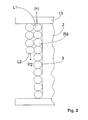
- Fig. 2 illustrates a side by side and superimposed arrangement of the wound cable 3.
- the cable 3 for example, already has eight rows, which the row R8 in Fig. 2 corresponds, the cable 3 moves in the direction of the arrow P1 until the first layer L1 is full. Thereafter, the direction of movement is reversed, which corresponds to the arrow P2.
- a second layer L2 is wound on the first layer, such as Fig. 2 shows. In this way, several layers L1 to Lx can be wound.
- Fig. 3 another embodiment of the mechanical coupling element 20 is shown.
- the guide roller 6 is connected by a belt 14 to the cable drum 6.
- a smaller roller 16 is arranged on the drum 6 in relation to both diameters d1, d2, so that only one fraction of a revolution is given to the roller 6 during one drum rotation.
- d1 is the effective drum diameter
- d2 is the effective roll diameter.
- Fig. 4 shows that the guide structure comprises a groove or groove 17, in which the cable 3 is placed.
- the cable 3 is, for example, a three-core power cable with the wires L, N, PE. Alternatively, it is a two-core cable. This lies between two walls 18 and 19 of the groove or groove, which are correspondingly in cable direction K (see. Fig. 1 ) are inclined.
- the groove 17 may be rectangular, triangular, domed, trapezoidal, as in FIG Fig. 4 is shown or have a different shape.
- the cable 3 should be easily freely movable within the walls 18, 19.
- not shown means are provided which prevent the cable 3 from the groove or groove 17 (in the figure above) evades.
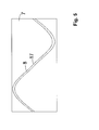
- Fig. 5 shows a winding of the lateral surface of the roller 6 according to the variant in Fig. 1 ,
- the groove or the groove 17 extends in an oscillating manner, for example sinusoidally, over the lateral surface 7 in the cable direction.
- the cable 3 can oscillate during a rotational movement of the roller 6.
- An oscillating groove course can also be zigzag or triangular. This has the advantage of uniform cable winder.
- the groove 17 may extend helically over the lateral surface, as in FIG Fig. 6 is shown. If the roller 6 is rotated in the direction of arrow r2, then the cable 3 can only move in the direction of the arrow P1. Thus, only a single layer L1 is possible (see. Fig. 2 ).
- Figures 9 and 10 show a trained in the form of a paddle guide roller 6.
- the axis of rotation D2 of the guide roller 6 extends in the plane of the guide roller 6.
- the paddle is wound around the axis D2 of the guide roller 6, that the axially outer edges 26, 27 substantially perpendicular to each other run.
- the guide roller 6 is mounted at the ends 11 and 22, that is mounted on both sides. A coupling of the roller 6 with the drum 2 can be done at both ends, with two coupling elements 20 should be used. This creates a uniform power transmission.
- Fig. 7 shows how the cable winding device 1 is integrated in a device and comprises a device feed line or a cable 3.
- the device may be a vacuum cleaner or other electrical device.
- Fig. 8 shows.
- the cable drum 2 comprises feet 21 and at least one connecting arm 24 which supports the roller 6.
- a pressing element for example a pressure roller 25, prevents the cable 3 from running out of the groove 17.
- the guide roller 6 may have the 0.1 to 0.5 times the diameter of the cable drum 2.
- the invention achieves easy winding and also easy removal of the cable 3 with simple and cost-effective constructive means.
Landscapes
- Storing, Repeated Paying-Out, And Re-Storing Of Elongated Articles (AREA)
- Guides For Winding Or Rewinding, Or Guides For Filamentary Materials (AREA)
Abstract
Description
- Die Erfindung betrifft eine Kabelwickelvorrichtung, die mit einer um eine Drehachse drehbare Kabeltrommel zum Aufnehmen eines in der Trommel aufwickelbaren Stromkabels versehen ist und die ein Führungsmittel zum Führen des Kabels während eines Kabelwickelvorgangs aufweist.
- Bei Kabeltrommeln für stromführende Leitungen besteht das Problem, dass das Kabel nur schwer sauber in mehrere neben und übereinander liegende Lagen bringbar ist. Daher werden in der Praxis die Leitungen eher ungeordnet in der Kabeltrommel aufgespult. Ein Ausziehen des ungeordneten Kabels ist häufig mit einem Einklemmen verbunden, was die Handhabung erschweren und die Leitungen mechanisch stark beanspruchen kann.
- Aus der Patentschrift
US 2 996 584 ist eine Kabeltrommel bekannt, die im Bereich des Kabeleinlaufs eine Führung mit zwei gegenüberliegenden genuteten Rollen aufweist, zwischen denen das Kabel läuft. Die Führung wird an einem Arm hin und her bewegt, um das Kabel geordnet aufzurollen. Die PatentschriftUS 1 747 411 A1 offenbart eine Lösung, bei der eine Kabelführung entlang einer sich parallel zur Trommelachse erstreckenden Welle hin und her läuft, um ein geordnetes Aufwickeln des Kabels zu ermöglichen. - Die Offenlegungsschrift
DE 199 54 072 A1 offenbart ein Verfahren zum spaltfreien Aufwickeln eines Kabels, bei dem eine neue Windung unmittelbar neben die vorhergehende Windung gewickelt wird. Dazu wird der Auflaufwinkel des Kabels nachgeführt, wenn ein Detektor einen Spalt zwischen den letzten Windungen feststellt. Eine Führung zum Aufwickeln eines Kabels auf eine die Zugspannung konstant haltenden Kabelrolle. Dazu wird das Kabel durch eine auf einer Schiene laufenden Kabelführung geleitet. - Eine Lösung, bei der ein optimales Wickelbild des Kabels in der Kabeltrommel erreicht werden soll sowie Verknotungen des Kabels vermieden werden sollen, ist aus der
WO 03/01960 - Der Erfindung liegt die Aufgabe zugrunde, eine Kabelwickelvorrichtung zur Verwendung in elektrischen Geräten zu schaffen, mit der ein leichtgängiges Ausziehen der Zuleitung möglich ist.
- Die Bezugszeichen in sämtlichen Ansprüchen haben keine einschränkende Wirkung, sondern sollen lediglich deren Lesbarkeit verbessern.
- Die Lösung der gestellten Aufgabe gelingt durch eine Kabelwickelvorrichtung mit den Merkmalen des Anspruchs 1.
- Durch die Führungsrolle kann das Kabel auf einfache Weise synchron zur Drehbewegung der Kabeltrommel über die Breite der Kabeltrommel geführt werden. Gleichzeitig kann das Kabel vorteilhafterweise stabil in einer Ebene geführt werden. Die Verlagerung des Kabels auf der kabelführenden Rolle wird durch die Ausgestaltung der Rollenoberfläche bzw. ihrer Mantelfläche erreicht. Durch die Kopplung beider Rollen, und zwar der kabelaufnehmenden Trommel und der kabelführenden Rolle, kann eine Synchronisation zwischen der Verlagerung des Kabels im Bereich des Kabeleinlaufs und der gewünschten Aufwicklung erreicht werden. Das Kabel wird auf der Trommel geordnet nebeneinander gelegt, bis eine Kabelreihe gefüllt ist, danach wird die Richtung der Kabelbewegung quer zur Drehachse der Trommel umgedreht, so dass eine weitere Lage aufgewickelt wird. Durch die Verlagerung des Kabels wird das Kabel sukzessive lagenweise neben- und übereinander gelegt.
- Eine Kabelwickelvorrichtung der genannten Art kann sowohl in einem elektrischen Gerät, z.B. einem Staubsauger oder dergleichen, integriert oder aber auch als Kabeltrommel bzw. als Kabelverlängerung ausgeführt sein. Die Führungsrolle kann außerhalb eines Kabeltrommelraums oder -gehäuses angeordnet sein, vorzugsweise ist diese jedoch innerhalb des Kabeltrommelraums oder -gehäuses angeordnet.
- Durch die Erfindung kann nicht nur ein geordnetes uns platzsparendes Aufwickeln des Kabels erreicht werden, sondern eine einfache Konstruktion mit wenigen Bauteilen. Gerätezuleitungen können geordnet in einem Wickelraum der Kabeltrommel abgelegt werden. Vorteilhafterweise kann vermieden werden, dass die geordnet abgelegten Leitungswindungen beim Ausziehen untereinander verpressen, was zu einer unerwünscht starken Reibung zwischen den einzelnen Leitungslagen führen könnte. Zudem wird durch die kompakte Leitungsaufwicklung eine größere Kabellänge in der Trommel aufgenommen.
- Vorteilhafte Aus- und Weiterbildungen, welche einzeln oder in Kombination miteinander eingesetzt werden können, sind Gegenstand der abhängigen Ansprüche.
- Die Führungsstruktur der Führungsrolle befindet sich gewöhnlich auf der Mantelfläche der Führungsrolle. Besonders günstig ist es, wenn das Führungsmittel als eine Führungsrolle mit einer zur Drehachse der Trommel parallelen Achse ausgeführt ist. Dies kann wirksam einem Abrutschen des Kabels von der Führungsrolle vorbeugen. Vorzugsweise entspricht die Breite der Führungsrolle im Wesentlichen der Breite der Kabeltrommel. So kann vorteilhaft die gesamte Breite der Kabeltrommel zur geordneten Aufnahme des Kabels genutzt werden. Die Verlagerung ist vorzugsweise eine oszillierende Verlagerung, d.h., das Kabel wird zunächst entlang der Führungsrollenachse in eine Richtung verlagert, bis sich die Verlagerungsrichtung in die Gegenrichtung umkehrt. Besonders vorzugsweise oszilliert die Lage Kabel auf der Führungsrolle fortwährend entlang der Rollenachse hin und her.
- In einer vorteilhaften Weiterbildung der erfindungsgemäßen Vorrichtung ist vorgesehen, dass die Führungsrolle getriebemäßig mit der Kabeltrommel verbunden ist. Dadurch ist es möglich, die Führungsrolle auf die Drehbewegung der Kabeltrommel zu synchronisieren. Eine Synchronisation bedeutet hier, dass das Verhältnis beider Drehgeschwindigkeiten, d.h. der Trommel einerseits und der Führungsrolle andererseits, durch das Getriebe bestimmt wird. Außerdem wird die Antriebsenergie von der Kabeltrommel auf die Führungsrolle vorzugsweise über das Getriebe übertragen. Die Führungsrolle kann dabei direkt von der Kabeltrommel angetrieben werden, z.B. über Zahnräder an der Führungsrolle und der Kabeltrommel, oder sie können nur mittelbar, z.B. über ein oder mehrere zusätzliches Zahnräder, getriebemäßig verbunden sein. Der Antrieb der Führungsrolle kann auch beidseitig erfolgen, so dass z.B. an jedem Ende der Führungsrolle ein Zahnrad angeordnet ist.
- Vorzugsweise bildet die Führungsrolle an wenigstens einem Rollenende eine radial abstehende Scheibe oder einen radial abstehender Ring, die bzw. der mit dem Getriebe verbunden ist oder (einen Teil) dessen bildet. Radial abstehend bedeutet, dass der Durchmesser der Scheibe größer ist als der Durchmesser der Rolle. Diese Scheibe oder dieser Ring kann auf eine Stirnseite der Führungsrolle befestigt werden und greift insbesondere mittel- oder unmittelbar auf eine Trommelwange der Kabeltrommel. Es können ein oder zwei Trommelwangen so eingesetzt werden. Die Scheibe verhindert gleichzeitig, dass das Kabel herausfallen kann.
- Alternativ oder zusätzlich zu einem Zahnrad kann der Antrieb auch so ausgeführt sein, dass die Führungsrolle mit einem Riemen- oder Kettenantrieb mit der Kabeltrommel getriebemäßig verbunden ist.
- Eine besonders bevorzugte Weiterbildung der Erfindung zeichnet sich dadurch aus, dass die Führungsstruktur eine Rille oder eine Nut umfasst, in der das Kabel geführt wird. Die Rille oder Nut befindet sich vorzugsweise auf der Oberfläche der Führungsrolle. Das Kabel liegt im Bereich des Kabeleinlaufs bzw. Kabeleinlaufs in dieser Rille bzw. Nut. Die Rille bzw. Nut verläuft nicht senkrecht zur Drehachse der Führungsrolle sondern weist eine Richtungskomponente in Richtung der Drehachse auf. Auf diese Weise ist erreichbar, dass sich der Bereich der Nut, in dem das Kabel geführt wird, bei Rotation der Führungsrolle in Dichtung der Drehachse verlagert. Das Kabel folgt dieser Bewegung, wodurch es entlang der Drehachse der Kabeltrommel so bewegt wird, dass es nebeneinander geordnet liegen kann.
- Damit an den Enden der Führungsrolle eine Umkehr der Kabelbewegung und damit eine oszillierende Bewegung erfolgen kann, ist es zweckmäßig, dass die Rille oder die Nut sich oszillierend, z.B. zickzackartig oder sinusförmig, über der Mantelfläche in Kabelrichtung erstreckt. Die Führungsrolle kann auch in Form eines Paddels ausgebildet sein, wobei die Drehachse in der Fläche des Paddels liegt. Vorzugsweise ist das Paddel um die Drehachse verwunden, besonders vorzugsweise derart, dass die in Axialrichtung äußeren Kanten des Paddels im Wesentlichen senkrecht zueinander verlaufen.
- Von Vorteil kann es aber auch sein, wenn die Rille oder eine Nut sich schnecken- bzw. spiralförmig über der Mantelfläche erstreckt. Hierbei endet die Verlagerung nach einem Durchlauf, d.h. wenn das Kabel die Führungsrolle einmal durchlaufen hat, so dass eine einzige Lage auf der Kabeltrommel aufgewickelt wird. Durch einen geeigneten Mechanismus lässt sich die die Drehrichtung der Führungsrolle relativ zur Kabeltrommel umdrehen, so dass das Kabel sich auf der Führungsrolle hin- und her bewegen kann. Eine stabile Aufhängung der Führungsrolle kann sichergestellt werden, indem die Führungsrolle beidseitig gelagert ist.
- Besonders praktisch ist die Erfindung bei Geräten, die ein relativ langes Kabel, z.B. mindestens drei Meter, benötigen, wie ein Staubsauger oder ähnliches, und keinen manuellen Zugang zur Kabeltrommel haben. Vorzugsweise ist die Kabelwickelvorrichtung in einem Gerät integriert und umfasst eine Gerätezuleitung. Die Kabeltrommel kann mit einem Federelement verbindbar sein, welches ein automatisches Aufrollen erlaubt.
- Weitere vorteilhafte Ausgestaltungen werden nachfolgend an Hand eines in der Zeichnung dargestellten Ausführungsbeispiels, auf welchem die Erfindung jedoch nicht beschränkt ist, näher beschrieben.
- Es zeigt schematisch:
- Fig. 1
- eine Darstellung einer erfindungsgemäßen Kabelwickelvorrichtung,
- Fig. 2
- eine Darstellung einer Kabeltrommel mit aufgewickeltem Kabel,
- Fig. 3
- eine alternative Ausführungsform der Vorrichtung,
- Fig. 4
- eine Darstellung einer Nut in einer erfindungsgemäßen Führungsrolle,
- Fig. 5
- eine Darstellung eines ersten Nutverlaufs in abgewickelter Form,
- Fig. 6
- eine Darstellung eines zweiten Nutverlaufs,
- Fig. 7
- eine Darstellung eines Geräts mit integrierter Kabelwickelvorrichtung,
- Fig. 8
- eine Darstellung einer Variante der Kabeltrommel mit der Kabelwickelvorrichtung,
- Fig. 9
- eine erfindungsgemäße Führungsrolle in Form eines Paddels in perspektivischer Ansicht und
- Fig. 10
- die paddelartige Führungsrolle der
Fig. 9 in Richtung der Drehachse betrachtet. - Bei der nachfolgenden Beschreibung einer bevorzugten Ausführungsform der vorliegenden Erfindung bezeichnen gleiche Bezugszeichen gleiche oder vergleichbare Komponenten.
-
Fig. 1 zeigt eine Kabelwickelvorrichtung, die mit einer um eine Drehachse D1 drehbaren Kabeltrommel 2 zum Aufnehmen eines in der Trommel 2 aufwickelbaren Stromkabels 3 versehen ist. Weiterhin weist die Vorrichtung 1 ein Führungsmittel 4 zum Führen des Kabels 3 während eines Kabelwickelvorgangs auf. InFig. 1 sind mehrere Windungen 5 des Kabels 3 auf der Kabeltrommel 2 bereits aufgewickelt bzw. aufgespult. - Das Führungsmittel ist eine Führungsrolle 6 mit einer zur Drehachse D1 der Trommel 2 parallelen Achse D2. Weiterhin hat die Rolle 6 im Wesentlichen eine Breite B2, die der Breite B1 Kabeltrommel 2 entspricht, also der für die Führung des Kabels maßgeblichen mit gewickeltem Kabel belegbaren Breite. Zudem ist auf der Mantelfläche 7 der Rolle 6 eine Führungsstruktur 8 für das Kabel 3 vorhanden, wie in
Fig. 1 zu sehen ist. Wegen der Breite und der Führungsstruktur ist es nicht erforderlich, dass die Führungsrolle, wie z.B. inUS 1 747 411 A1 , parallel zu Trommelachse hin und her bewegt wird. Das Kabel 6 gleitet über die gesamte Breite B2 hin und her, wie die Pfeile P1 und P2 zeigen. - Außerdem wird die Führungsrolle 6 durch eine Drehbewegung der Kabeltrommel, d.h. um die Achse D1, derart angetrieben, dass das auf die Trommel 2 wickelbare Kabel 3 im Bereich eines Kabeleinlaufs 9 infolge der Führungsstruktur 8 eine oszillierende Verlagerung über die Breite B2 der Führungsrolle 6 ausführt. Wie auch in
Fig. 1 sehr prinziphaft dargestellt ist, ist die Führungsrolle 6 über mindestens ein Kopplungselement 20, vorzugsweise ein Reib- oder Zahnrad 10, insbesondere mit einem Getriebe, mit der Kabeltrommel 2 verbunden. Dieses Kopplungselement 20 kann so ausgeführt und mit beiden Rollen 2 und 6 so wirkverbunden sein, dass bei einer vollen Umdrehung der Führungsrolle 6 bereits ein Vielfaches an vollen Umdrehungen, z.B. 10 Umdrehungen, der Kabeltrommel 2 gegeben ist. - Die Führungsrolle 6 umfasst an wenigstens einem Rollenende 11 eine radial abstehende Scheibe 12 oder alternativ einen radial abstehenden Ring. Die Scheibe 12 ist mit dem Reib- oder Zahnrad 10 verbunden. Alternativ kann die Scheibe 12 auch direkt mit der Trommel 6 verbunden sein, wobei die Scheibe 12 das Kopplungselement 20 bildet.
- Wie auch in
Fig. 1 dargestellt ist, ist mindestens eine Trommelwange 13 mit dem Reiboder Zahnrad 10 verbunden. Die Trommelwange 13 ist im Prinzip ein Stirnrad bzw. eine Scheibe oder ein Ring, das an einer Stirnseite der Trommel 6 angeordnet ist. Wie bereits erwähnt, können sich die Trommelwange 13 und die Scheibe 12 auch direkt berühren. Wird eine Zahnradlösung eingesetzt, dann sind die Trommelwange 13 und die Scheibe 12 mit Zähnen versehen. Die Rolle 6 hat dann ebenfalls mindestens ein Stirnrad, vorzugsweise zwei Stirnräder. -
Fig. 2 verdeutlicht eine neben- und übereinanderliegende Anordnung des gewickelten Kabels 3. Ausgehend vonFig. 1 , bei der das Kabel 3 z.B. bereits acht Reihen hat, was der Reihe R8 inFig. 2 entspricht, bewegt sich das Kabel 3 weiter in Richtung des Pfeiles P1 bis die erste Lage L1 voll ist. Danach kehrt sich die Bewegungsrichtung um, was dem Pfeil P2 entspricht. Eine zweite Lage L2 wird auf der ersten Lage aufgewickelt, wieFig. 2 zeigt. Auf diese Weise können mehrere Lagen L1 bis Lx gewickelt werden. - In
Fig. 3 wird eine andere Ausführung des mechanischen Kopplungselementes 20 gezeigt. Die Führungsrolle 6 ist durch einen Riemen 14 mit der Kabeltrommel 6 verbunden. Hierbei ist trommelseitig eine im Verhältnis zu beiden Durchmessern d1, d2 kleinere Rolle 16 an der Trommel 6 angeordnet, so dass bei einer Trommelumdrehung nur ein Bruchteil einer Umdrehung an der Rolle 6 gegeben ist. Hierbei ist d1 der wirksame Trommeldurchmesser und d2 der wirksame Rollendurchmesser. -
Fig. 4 zeigt, dass die Führungsstruktur eine Rille oder eine Nut 17 umfasst, in die das Kabel 3 gelegt wird. Das Kabel 3 ist z.B. ein dreiadriges Stromkabel mit den Adern L, N, PE. Alternativ ist es ein lediglich zweiadriges Kabel. Dieses liegt zwischen zwei Wandungen 18 und 19 der Rille oder Nut, die entsprechend in Kabelrichtung K (vgl.Fig. 1 ) geneigt sind. Die Nut 17 kann rechteckförmig, dreieckförmig, gewölbt, trapezförmig sein, wie inFig. 4 gezeigt ist, oder eine andere Form haben. Das Kabel 3 sollte leicht frei beweglich innerhalb der Wandungen 18, 19 liegen. Außerdem sind nicht dargestellt Mittel vorgesehen, die verhindern, dass das Kabel 3 aus der Rille oder Nut 17 (in der Figur nach oben) ausweicht. -
Fig. 5 zeigt eine Aufwicklung der Mantelfläche der Rolle 6 gemäß der Variante inFig. 1 . Hierbei erstreckt sich die Rille oder die Nut 17 oszillierend, z.B. sinusförmig, über der Mantelfläche 7 in Kabelrichtung. Dadurch kann das Kabel 3 bei einer Drehbewegung der Rolle 6 oszillieren. Ein oszillierender Rillenverlauf kann auch zickzack- bzw. dreieckförmig sein. Dies hat den Vorteil einer gleichmäßigen Kabelaufwicklung. - Alternativ kann die Nut 17 sich schnecken- bzw. spiralförmig über der Mantelfläche erstrecken, wie in
Fig. 6 dargestellt ist. Wird die Rolle 6 in Pfeilrichtung r2 gedreht, dann kann sich das Kabel 3 nur in Richtung des Pfeiles P1 bewegen. Somit ist nur eine einzige Lage L1 möglich (vgl.Fig. 2 ). -
Figuren 9 und10 zeigen eine in Form eines Paddels ausgebildete Führungsrolle 6. Die Drehachse D2 der Führungsrolle 6 verläuft in der Ebene der Führungsrolle 6. Das Paddel ist derart um die Achse D2 der Führungsrolle 6 verwunden, dass die in Axialrichtung äußeren Kanten 26, 27 im Wesentlichen senkrecht zueinander verlaufen. - Die Führungsrolle 6 ist an den Enden 11 und 22 gelagert, also beidseitig gelagert. Eine Kopplung der Rolle 6 mit der Trommel 2 kann an beiden Enden erfolgen, wobei zwei Kopplungselemente 20 verwendet werden müssten. Dies schafft eine gleichmäßige Kraftübertragung.
-
Fig. 7 zeigt, wie die Kabelwickelvorrichtung 1 in einem Gerät integriert ist und eine Gerätezuleitung bzw. ein Kabel 3 umfasst. Das Gerät kann ein Staubsauger oder ein anderes elektrisches Gerät sein. Aber auch die Verwendung der Erfindung in einer Verlängerungstrommel zur Kabelverlängerung ist möglich, wieFig. 8 zeigt. Die Kabeltrommel 2 umfasst Standfüße 21 und mindestens einen Verbindungsarm 24, der die Rolle 6 haltert. Durch ein Anpresselement, z.B. eine Anpressrolle 25, wird verhindert, dass das Kabel 3 aus der Nut 17 läuft. Die Führungsrolle 6 kann den 0,1- bis 0,5-fachen Durchmesser der Kabeltrommel 2 aufweisen. - Durch die Erfindung wird mit einfachen und kostengünstigen konstruktiven Mitteln ein leichtes Aufwickeln aber auch ein leichtes Ausziehen des Kabels 3 erreicht.
- Die in der vorstehenden Beschreibung, den Ansprüchen und den Zeichnungen offenbarten Merkmale können sowohl einzeln als auch in beliebiger Kombination für die Verwirklichung der Erfindung in ihren verschiedenen Ausgestaltungen von Bedeutung sein. So kann beispielsweise die Rolle 25 in
Fig. 8 ohne Weiteres auch bei den Ausführungsformen gemäßFig. 1 ,6 oder7 verwendet werden. -
- 1.
- Kabelwickelvorrichtung
- 2.
- Kabeltrommel
- 3.
- Stromkabel
- 4.
- Führungsmittel
- 5.
- Windungen
- 6.
- Führungsrolle
- 7.
- Mantelfläche
- 8.
- Führungsstruktur
- 9.
- Kabeleinlauf
- 10.
- Reib- oder Zahnrad
- 11.
- Rollenende
- 12.
- Scheibe
- 13.
- Trommelwange
- 14.
- Riemen
- 16.
- Rolle
- 17.
- Nut
- 18.
- erste Wandung
- 19.
- zweite Wandung
- 20.
- Kopplungselement
- 21.
- Standfüße
- 22.
- zweites Ende
- 23.
- Gerät
- 24.
- Verbindungsarm
- 25.
- Anpressrolle
- 26.
- Kante einer paddelartigen Führungsrolle
- 27.
- Kante einer paddelartigen Führungsrolle
- B1, B2
- Breiten
- D1, D2
- Drehachsen
- d1, d2
- Durchmesser
- L1, L2
- Lagen
Claims (10)
- Kabelwickelvorrichtung (1), die mit einer um eine Drehachse (D1) drehbare Kabeltrommel (2) zum Aufnehmen eines in der Trommel (2) aufwickelbaren Stromkabels (3) versehen ist und die ein Führungsmittel (4) zum Führen des Kabels (3) während eines Kabelwickelvorgangs aufweist, dadurch gekennzeichnet,
dass die Führungsrolle (6) eine Führungsstruktur (8) für das Kabel (3) aufweist, wobei die Führungsrolle (6) durch eine Drehbewegung der Kabeltrommel (2) derart angetrieben wird, dass das auf die Trommel (2) wickelbare Kabel (3) im Bereich eines Kabeleinlaufs (9) infolge der Führungsstruktur (8) entlang der Achse der Führungsrolle (6) verlagert wird. - Kabelwickelvorrichtung nach Anspruch 1, dadurch gekennzeichnet, dass das Führungsmittel (4) als eine Führungsrolle (6) mit einer zur Drehachse (D1) der Trommel parallelen Achse (D2) ausgeführt ist.
- Kabelwickelvorrichtung nach einem der vorherigen Ansprüche, dadurch gekennzeichnet, dass die Führungsrolle (6) das Kabel (3) oszillierend verlagert.
- Kabelwickelvorrichtung nach einem der vorherigen Ansprüche, dadurch gekennzeichnet, dass die Führungsrolle (6) getriebemäßig mit der Kabeltrommel (2) verbunden ist.
- Kabelwickelvorrichtung nach Anspruch 3 oder 4, dadurch gekennzeichnet, dass mindestens eine Trommelwange (13) mit dem Reib- oder Zahnrad (10) verbunden ist.
- Kabelwickelvorrichtung nach einem der vorherigen Ansprüche, dadurch gekennzeichnet, dass die Führungsrolle (6) mit einem Riemen- oder Kettenantrieb mit der Kabeltrommel (2) verbunden ist.
- Kabelwickelvorrichtung nach einem der vorherigen Ansprüche, dadurch gekennzeichnet, dass die Führungsstruktur (8) eine Rille oder eine Nut (17) umfasst, in der das Kabel (3) geführt wird.
- Kabelwickelvorrichtung nach Anspruch 7, dadurch gekennzeichnet, dass die Rille oder die Nut (17) sich oszillierend, vorzugsweise zickzack- oder sinusförmig, über der Mantelfläche (7) in Kabelrichtung erstreckt.
- Kabelwickelvorrichtung nach Anspruch 7, dadurch gekennzeichnet, dass die Rille oder die Nut (17) sich schnecken- bzw. spiralförmig über der Mantelfläche (7) erstreckt.
- Kabelwickelvorrichtung nach einem der vorherigen Ansprüche, dadurch gekennzeichnet, dass die Kabelwickelvorrichtung (1) in einem Gerät (23) integriert ist und eine Gerätezuleitung umfasst und/oder dass die Führungsrolle (6) in einem Rollengehäuse integriert ist.
Applications Claiming Priority (1)
| Application Number | Priority Date | Filing Date | Title |
|---|---|---|---|
| DE201010039287 DE102010039287A1 (de) | 2010-08-12 | 2010-08-12 | Kabelwickelvorrichtung |
Publications (2)
| Publication Number | Publication Date |
|---|---|
| EP2418165A2 true EP2418165A2 (de) | 2012-02-15 |
| EP2418165A3 EP2418165A3 (de) | 2013-01-02 |
Family
ID=44644964
Family Applications (1)
| Application Number | Title | Priority Date | Filing Date |
|---|---|---|---|
| EP11176305A Withdrawn EP2418165A3 (de) | 2010-08-12 | 2011-08-02 | Kabelwickelvorrichtung |
Country Status (3)
| Country | Link |
|---|---|
| EP (1) | EP2418165A3 (de) |
| CN (1) | CN102424305A (de) |
| DE (1) | DE102010039287A1 (de) |
Cited By (1)
| Publication number | Priority date | Publication date | Assignee | Title |
|---|---|---|---|---|
| CN111926878A (zh) * | 2019-05-13 | 2020-11-13 | 山东德曼机械有限公司 | 一种电缆绞盘同步的电动装载机 |
Citations (4)
| Publication number | Priority date | Publication date | Assignee | Title |
|---|---|---|---|---|
| US1747411A (en) | 1924-10-25 | 1930-02-18 | Appleton Electric Co | Combined cord reel and conductor distributor |
| US2996584A (en) | 1956-06-05 | 1961-08-15 | United Specialties Inc | Electric cable reel |
| DE19954072A1 (de) | 1999-11-10 | 2001-05-17 | Siemens Ag | Verfahren und Vorrichtung zum Aufwickeln von Kabeln auf eine Kabeltrommel |
| WO2003001960A1 (de) | 2001-06-29 | 2003-01-09 | BSH Bosch und Siemens Hausgeräte GmbH | Vorrichtung zum speichern eines kabels |
Family Cites Families (9)
| Publication number | Priority date | Publication date | Assignee | Title |
|---|---|---|---|---|
| US2133551A (en) * | 1937-07-23 | 1938-10-18 | Logan Donald Gibson | Cord reel |
| CH570928A5 (en) * | 1974-04-29 | 1975-12-31 | Aied Textile Mach | Yarn or cord traverse guide - for winding-up textile or other filiform products on collecting bobbins, with sectorial guide teeth |
| DE3027119C2 (de) * | 1980-07-17 | 1982-10-28 | Siemens AG, 1000 Berlin und 8000 München | Kabelaufrollvorrichtung für ein Reinigungsgerät |
| JPS58119565A (ja) * | 1982-01-06 | 1983-07-16 | Hitachi Ltd | ケ−ブルリ−ル装置 |
| JPS61254135A (ja) * | 1985-05-01 | 1986-11-11 | 株式会社 小野寺鉄工所 | 延縄漁用枝縄巻取装置 |
| US5375786A (en) * | 1992-08-19 | 1994-12-27 | Ta-Yueh; Hsu | Winding apparatus with a guidance device for wire or the like |
| DE20300805U1 (de) * | 2003-01-20 | 2003-03-27 | Mura-Metalltechnik GmbH, 48683 Ahaus | Vorrichtung zur Halterung von Leitungen |
| DE202006004652U1 (de) * | 2006-03-23 | 2006-07-13 | Hansen, Thomas | Handbetätigte Wickelvorrichtung für mobile tragbare Trommel für Wickelgut |
| CN201052938Y (zh) * | 2007-07-12 | 2008-04-30 | 徐卓华 | 一种绕线机的导线机构 |
-
2010
- 2010-08-12 DE DE201010039287 patent/DE102010039287A1/de not_active Withdrawn
-
2011
- 2011-08-02 EP EP11176305A patent/EP2418165A3/de not_active Withdrawn
- 2011-08-12 CN CN2011102310579A patent/CN102424305A/zh active Pending
Patent Citations (4)
| Publication number | Priority date | Publication date | Assignee | Title |
|---|---|---|---|---|
| US1747411A (en) | 1924-10-25 | 1930-02-18 | Appleton Electric Co | Combined cord reel and conductor distributor |
| US2996584A (en) | 1956-06-05 | 1961-08-15 | United Specialties Inc | Electric cable reel |
| DE19954072A1 (de) | 1999-11-10 | 2001-05-17 | Siemens Ag | Verfahren und Vorrichtung zum Aufwickeln von Kabeln auf eine Kabeltrommel |
| WO2003001960A1 (de) | 2001-06-29 | 2003-01-09 | BSH Bosch und Siemens Hausgeräte GmbH | Vorrichtung zum speichern eines kabels |
Cited By (1)
| Publication number | Priority date | Publication date | Assignee | Title |
|---|---|---|---|---|
| CN111926878A (zh) * | 2019-05-13 | 2020-11-13 | 山东德曼机械有限公司 | 一种电缆绞盘同步的电动装载机 |
Also Published As
| Publication number | Publication date |
|---|---|
| EP2418165A3 (de) | 2013-01-02 |
| CN102424305A (zh) | 2012-04-25 |
| DE102010039287A1 (de) | 2012-02-16 |
Similar Documents
| Publication | Publication Date | Title |
|---|---|---|
| DE2525762C3 (de) | Vorrichtung zum lagenweisen Aufwickeln eines Kabels o.dgL auf eine Kabeltrommel | |
| DE2542124A1 (de) | Einrichtung zum stapeln von kontinuierlich, insbesondere in einer schuppenformation auf einer foerderbahn anfallenden druckprodukten | |
| DE69900555T2 (de) | Verfahren und vorrichtung zur übertragung von druck und/oder zugkraft | |
| DE4419853C1 (de) | Rollo oder dergleichen | |
| DE1817803C3 (de) | Rotierender Zwischenspeicher zur Verseilung von Verseilelementen für Kabel, insbesondere Nachrichtenkabel. Ausscheidung aus: 1801089 | |
| DE4006212C2 (de) | Jalousie | |
| CH619906A5 (de) | ||
| DE2713027A1 (de) | Vorrichtung zum aufwickeln unter verwendung von haftreibung von seilen aller art | |
| DE3133842C2 (de) | Vorrichtung zum betriebsmäßigen Auf- und Abwickeln von Elektrokabel | |
| EP2720970B1 (de) | Vorrichtung zum ab- und aufwickeln einer oder mehreren leitungen | |
| DE102010039287A1 (de) | Kabelwickelvorrichtung | |
| DE102006056244A1 (de) | Vorrichtung zum Auf- und Abwickeln von strangartigem Wickelgut | |
| EP0652176A1 (de) | Wickelvorrichtung für flexible Flächengebilde sowie Verfahren zum Aufwickeln von flexiblen Flächengebilden | |
| DE3133149C2 (de) | Legemaschine | |
| DE3347499A1 (de) | Verfahren und vorrichtung zur wahlweisen freigabe einer vorbestimmten schussfadenlaenge an schuetzenlosen webmaschinen | |
| AT370348B (de) | Seilzugvorrichtung fuer die fremdangel einer rohr- und stangenziehmaschine | |
| DE3700546C2 (de) | ||
| DD201578A5 (de) | Bandwickelmaschine | |
| EP3894103A1 (de) | Werkzeug-transfervorrichtung | |
| DE4020148C2 (de) | ||
| EP2239356A1 (de) | Musterkettenschärmaschine und Verfahren zum Betreiben einer Musterkettenschärmaschine | |
| DE102007036288B4 (de) | Seilzugantrieb und Salatschleuder mit Seilzugantrieb | |
| DE3711187A1 (de) | Verfahren zum herstellen eines kabels, vorrichtung zur verfahrensdurchfuehrung und kabel | |
| DE2143433C3 (de) | Vorrichtung zum Abwickeln eines schraubenförmig gewickelten elastischen Stranges, insbesondere einer Kabelschnur | |
| DE2816392C3 (de) | Verfahren zum SZ-Verseilen einzelner oder in Bündeln verdrillt oder unverdrillt zusammengefaßter Verseilelemente und Vorrichtung zu seiner Durchführung |
Legal Events
| Date | Code | Title | Description |
|---|---|---|---|
| AK | Designated contracting states |
Kind code of ref document: A2 Designated state(s): AL AT BE BG CH CY CZ DE DK EE ES FI FR GB GR HR HU IE IS IT LI LT LU LV MC MK MT NL NO PL PT RO RS SE SI SK SM TR |
|
| AX | Request for extension of the european patent |
Extension state: BA ME |
|
| PUAI | Public reference made under article 153(3) epc to a published international application that has entered the european phase |
Free format text: ORIGINAL CODE: 0009012 |
|
| PUAL | Search report despatched |
Free format text: ORIGINAL CODE: 0009013 |
|
| AK | Designated contracting states |
Kind code of ref document: A3 Designated state(s): AL AT BE BG CH CY CZ DE DK EE ES FI FR GB GR HR HU IE IS IT LI LT LU LV MC MK MT NL NO PL PT RO RS SE SI SK SM TR |
|
| AX | Request for extension of the european patent |
Extension state: BA ME |
|
| RIC1 | Information provided on ipc code assigned before grant |
Ipc: B65H 75/44 20060101ALI20121126BHEP Ipc: B65H 75/42 20060101AFI20121126BHEP |
|
| 17P | Request for examination filed |
Effective date: 20130702 |
|
| RBV | Designated contracting states (corrected) |
Designated state(s): AL AT BE BG CH CY CZ DE DK EE ES FI FR GB GR HR HU IE IS IT LI LT LU LV MC MK MT NL NO PL PT RO RS SE SI SK SM TR |
|
| STAA | Information on the status of an ep patent application or granted ep patent |
Free format text: STATUS: THE APPLICATION IS DEEMED TO BE WITHDRAWN |
|
| 18D | Application deemed to be withdrawn |
Effective date: 20130703 |