EP2418144A1 - Lagerplattform zum Lagern mindestens eines Aggregats in einem Unterseeboot - Google Patents
Lagerplattform zum Lagern mindestens eines Aggregats in einem Unterseeboot Download PDFInfo
- Publication number
- EP2418144A1 EP2418144A1 EP11177160A EP11177160A EP2418144A1 EP 2418144 A1 EP2418144 A1 EP 2418144A1 EP 11177160 A EP11177160 A EP 11177160A EP 11177160 A EP11177160 A EP 11177160A EP 2418144 A1 EP2418144 A1 EP 2418144A1
- Authority
- EP
- European Patent Office
- Prior art keywords
- bearing
- platform
- viscoelastic
- beams
- submarine
- Prior art date
- Legal status (The legal status is an assumption and is not a legal conclusion. Google has not performed a legal analysis and makes no representation as to the accuracy of the status listed.)
- Granted
Links
Images

Classifications
-
- B—PERFORMING OPERATIONS; TRANSPORTING
- B63—SHIPS OR OTHER WATERBORNE VESSELS; RELATED EQUIPMENT
- B63G—OFFENSIVE OR DEFENSIVE ARRANGEMENTS ON VESSELS; MINE-LAYING; MINE-SWEEPING; SUBMARINES; AIRCRAFT CARRIERS
- B63G8/00—Underwater vessels, e.g. submarines; Equipment specially adapted therefor
- B63G8/08—Propulsion
-
- B—PERFORMING OPERATIONS; TRANSPORTING
- B63—SHIPS OR OTHER WATERBORNE VESSELS; RELATED EQUIPMENT
- B63G—OFFENSIVE OR DEFENSIVE ARRANGEMENTS ON VESSELS; MINE-LAYING; MINE-SWEEPING; SUBMARINES; AIRCRAFT CARRIERS
- B63G8/00—Underwater vessels, e.g. submarines; Equipment specially adapted therefor
- B63G8/28—Arrangement of offensive or defensive equipment
- B63G8/34—Camouflage
-
- B—PERFORMING OPERATIONS; TRANSPORTING
- B63—SHIPS OR OTHER WATERBORNE VESSELS; RELATED EQUIPMENT
- B63H—MARINE PROPULSION OR STEERING
- B63H21/00—Use of propulsion power plant or units on vessels
- B63H21/30—Mounting of propulsion plant or unit, e.g. for anti-vibration purposes
-
- B—PERFORMING OPERATIONS; TRANSPORTING
- B63—SHIPS OR OTHER WATERBORNE VESSELS; RELATED EQUIPMENT
- B63H—MARINE PROPULSION OR STEERING
- B63H21/00—Use of propulsion power plant or units on vessels
- B63H21/30—Mounting of propulsion plant or unit, e.g. for anti-vibration purposes
- B63H21/305—Mounting of propulsion plant or unit, e.g. for anti-vibration purposes with passive vibration damping
-
- F—MECHANICAL ENGINEERING; LIGHTING; HEATING; WEAPONS; BLASTING
- F16—ENGINEERING ELEMENTS AND UNITS; GENERAL MEASURES FOR PRODUCING AND MAINTAINING EFFECTIVE FUNCTIONING OF MACHINES OR INSTALLATIONS; THERMAL INSULATION IN GENERAL
- F16F—SPRINGS; SHOCK-ABSORBERS; MEANS FOR DAMPING VIBRATION
- F16F15/00—Suppression of vibrations in systems; Means or arrangements for avoiding or reducing out-of-balance forces, e.g. due to motion
- F16F15/02—Suppression of vibrations of non-rotating, e.g. reciprocating systems; Suppression of vibrations of rotating systems by use of members not moving with the rotating systems
- F16F15/04—Suppression of vibrations of non-rotating, e.g. reciprocating systems; Suppression of vibrations of rotating systems by use of members not moving with the rotating systems using elastic means
- F16F15/08—Suppression of vibrations of non-rotating, e.g. reciprocating systems; Suppression of vibrations of rotating systems by use of members not moving with the rotating systems using elastic means with rubber springs ; with springs made of rubber and metal
-
- F—MECHANICAL ENGINEERING; LIGHTING; HEATING; WEAPONS; BLASTING
- F16—ENGINEERING ELEMENTS AND UNITS; GENERAL MEASURES FOR PRODUCING AND MAINTAINING EFFECTIVE FUNCTIONING OF MACHINES OR INSTALLATIONS; THERMAL INSULATION IN GENERAL
- F16F—SPRINGS; SHOCK-ABSORBERS; MEANS FOR DAMPING VIBRATION
- F16F9/00—Springs, vibration-dampers, shock-absorbers, or similarly-constructed movement-dampers using a fluid or the equivalent as damping medium
- F16F9/30—Springs, vibration-dampers, shock-absorbers, or similarly-constructed movement-dampers using a fluid or the equivalent as damping medium with solid or semi-solid material, e.g. pasty masses, as damping medium
- F16F9/306—Springs, vibration-dampers, shock-absorbers, or similarly-constructed movement-dampers using a fluid or the equivalent as damping medium with solid or semi-solid material, e.g. pasty masses, as damping medium of the constrained layer type, i.e. comprising one or more constrained viscoelastic layers
-
- B—PERFORMING OPERATIONS; TRANSPORTING
- B63—SHIPS OR OTHER WATERBORNE VESSELS; RELATED EQUIPMENT
- B63G—OFFENSIVE OR DEFENSIVE ARRANGEMENTS ON VESSELS; MINE-LAYING; MINE-SWEEPING; SUBMARINES; AIRCRAFT CARRIERS
- B63G13/00—Other offensive or defensive arrangements on vessels; Vessels characterised thereby
- B63G13/02—Camouflage
- B63G2013/022—Camouflage using means for reducing noise emission into air or water
Definitions
- the invention relates to a storage platform for storing at least one unit in a submarine with the features specified in the preamble of claim 1.
- the storage platforms are in turn mounted elastically on a boat foundation connected to the pressure hull of the submarine.
- the storage platforms are made of prefabricated steel profiles, preferably double-T beams and other custom-made steel components, the double-T beams forming a bearing structure of the bearing platform.
- the present invention seeks to provide a storage platform for storing aggregates in a submarine whose natural frequency excitation leads to significantly lower structure-borne noise levels.
- the storage platform according to the invention for storing at least one unit in a submarine has at least two bearing parts.
- These bearing parts are inherently rigid, so that they do not deform themselves due to the force exerted by the unit to be stored weight.
- the bearing parts may be formed of steel or a material having similar strength properties.
- the bearing parts are interconnected by means of a viscoelastic layer. It is therefore provided between the bearing parts, a layer of viscoelastic material, which creates a two-dimensional adhesion between the bearing parts.
- the ability of viscoelastic materials is advantageously exploited to resiliently yield due to their elastic properties, but at the same time exercise the function of a damping element because of their viscous properties.
- the viscoelastic layer between the bearing parts with a suitable arrangement and design acts as a spring damping element within the bearing platform, with which the structure-borne noise level can be significantly reduced at a natural frequency excitation of the bearing platform.
- the at least two-part design of the bearing platform also allows, if appropriate, to use bearing parts made of different materials.
- the bearing platform according to the invention may consist of more than two bearing parts, wherein the adjacently arranged bearing parts connecting viscoelastic layers may optionally be aligned in obliquely or preferably mutually perpendicular planes.
- the viscoelastic layers may, for example, be oriented normal and parallel to a weight force acting on the support platform.
- the thickness of the viscoelastic layers in the connecting direction of the bearing parts is expediently selected as a function of the weight of the aggregates mounted on the bearing platform and / or as a function of the natural vibration excitations of the bearing platform caused by these aggregates.
- the viscoelastic layer aligned between the bearing parts in a main extension direction of the bearing parts.
- a main extension direction of the bearing parts is to be understood a direction in which the bearing parts have the largest possible and preferably their largest dimensions.
- To create the largest possible contact surfaces between the viscoelastic layer and the bearing parts to be joined is further advantageous to arrange the viscoelastic layer between two oriented in a main extension direction of the bearing parts flat sides of the bearing parts.
- a viscoelastic material can be introduced in liquid form into a space between two adjacent bearing parts to be joined together, where it cures and creates a material connection of the bearing parts.
- the bearing parts can be glued together with an adhesive tape having viscoelastic properties. It can therefore be used to connect the bearing parts of an adhesive tape with a viscoelastic support material, which is suitably coated on both sides with a pressure-sensitive adhesive.
- the adhesive tape can optionally be single-layered, but also be arranged in several layers between the bearing parts.
- the bearing platform preferably has a support structure whose supports are formed of at least paired intrinsically rigid profile elements, wherein the profile elements are connected to a viscoelastic layer.
- both the same and different profile elements can be connected to one another by means of the viscoelastic layer.
- one or more aggregates may be mounted elastically directly or indirectly, for example on a plate arranged on the support structure.
- two or more profile elements are used to form the carriers, wherein the viscoelastic layer arranged between the profile elements imparts an internal vibration damping capability to the individual carriers of the carrier structure without substantially influencing the static rigidity of the carrier structure.
- the profile elements used to form the carrier can, for. B. be commercially available profile steel elements.
- the shape of the support structure is basically arbitrary.
- the support structure is designed as a frame and preferably as a rectangular frame.
- the supports forming the support structure can be connected to one another in such a way that they laterally enclose a free space, preferably closed.
- the frame may have an inner frame of interconnected U-beams. Under U-beams are understood in the usual sense elongated support members with a U-profile.
- the inner frame advantageously forms a rigid structure, which gives the bearing device according to the invention a basic rigidity.
- the legs of the inner frame forming U-beam are preferably directed into the interior of the frame. Accordingly, the inner frame has flat surfaces on all outer sides, on which further profile elements can be fastened in a quick and simple manner via viscoelastic layers.
- the webs of the U-beams to be joined together have the same width, so that the legs (also referred to as flanges) of these U-beams together form a flat outer side.
- the flat sides of the webs of the U-beams to be joined together face each other, with a respective viscoelastic layer being arranged between the webs.
- this embodiment may be attached to the outer sides of the legs of the U-beams in each case by means of a viscoelastic layer strips. That is, on the outside of the projecting in opposite directions legs of each other in the region of the webs by means of a viscoelastic layer connected U-beams are attached via further viscoelastic layers strips so that each of the frame forming carrier within the carrier has three viscoelastic layers, wherein serving to attach the strips viscoelastic layers normal to the U-profiles interconnecting viscoelastic layer are aligned, thus allowing in the carriers a natural vibration damping in different directions.
- the width of the strips attached to the legs of the U-beams corresponds to the total length of the adjoining legs of the U-beams.
- the storage platform according to the invention is intended for use in a submarine.
- a submarine also forms part of the invention.
- This submarine has a bearing device for supporting at least one unit, which is elastically mounted on a rigidly connected to the pressure body foundation, such as a deck.
- a part of the storage device is a storage platform with the features and advantages described above, in which caused by the units to be stored natural vibration excitations of the bearing platform are not transferred in the best case to the pressure hull of the submarine.
- a deck 4 is arranged, which forms a foundation for a storage device 6.
- the deck 4 is rigidly connected in the usual way with the wall of the pressure hull 2.
- the storage device 6 is used for storage of aggregates 8, which are placed there elastically mounted on a bearing platform 10 on rubber springs 12.
- the bearing platform 10 is mounted on the deck 4 elastically via spring elements 14.
- the storage platform 10 has a support structure in the form of a rectangular frame 16 ( Fig. 2 ).
- the frame 16 are two U-shaped in cross-section support 18, hereinafter called U-carrier, and two U-beam 20 are joined together via welded joints to form a rigid inner frame 22, wherein the legs 21 of the U-beams 18 and 20 in the interior of the frame 16 have. All U-beams used 18 and 20 are made of steel.
- adhesive tapes 24 are glued to the webs 23 of all U-beams 18 and 20 on the side remote from the projecting legs 21 flat side.
- Adhesive tapes 24 are double-sided adhesive tapes 24 whose carrier material has viscoelastic properties.
- a further U-carrier 18 and 20, respectively bonded At the side facing away from the U-beams 18 and 20 sides of the attached to the U-beams 18 and 20 adhesive tapes 24 is a further U-carrier 18 and 20, respectively bonded.
- the interconnected U-beams 18 and 20 have mutually corresponding dimensions.
- a further double-sided adhesive tape 26 is attached in each case.
- the carrier material of the adhesive tape 26 also has viscoelastic properties.
- flat strips 28 which are formed as the U-beams 18 and 20 made of steel, attached to the U-beams 18 and 20.
- the interconnected U-beams 18 and 20 and the strips 28 support elements of the frame 16 with a double-T profile.
- the viscoelastic layers formed by the adhesive tapes 24 and 26 between adjacent bearing parts, ie the U-beams 18 and 20 and the strips 28, give the bearing platform 10 an internal damping which, with self-oscillation excitation of the bearing platform 10, the development of structure-borne noise and transmission of structure-borne noise hindered on the pressure hull 2 of the submarine and prevented at best.
Landscapes
- Engineering & Computer Science (AREA)
- Mechanical Engineering (AREA)
- General Engineering & Computer Science (AREA)
- Chemical & Material Sciences (AREA)
- Combustion & Propulsion (AREA)
- Aviation & Aerospace Engineering (AREA)
- Ocean & Marine Engineering (AREA)
- Physics & Mathematics (AREA)
- Acoustics & Sound (AREA)
- Vibration Prevention Devices (AREA)
- Springs (AREA)
- Vibration Dampers (AREA)
Abstract
Description
- Die Erfindung betrifft eine Lagerplattform zum Lagern mindestens eines Aggregats in einem Unterseeboot mit den im Oberbegriff des Anspruchs 1 angegebenen Merkmalen.
- Es ist bekannt, in militärischen Unterseebooten Aggregate, wie Antriebsmotoren, Pumpen und dergleichen elastisch auf Lagerplattformen zu lagern, wobei die Lagerplattformen wiederum elastisch auf einem mit dem Druckkörper des Unterseeboots verbundenen Bootsfundament gelagert sind. Die Lagerplattformen werden aus vorgefertigten Stahlprofilen, vorzugsweise Doppel-T-Trägern und anderen speziell angefertigten Stahlbauteilen gefertigt, wobei die Doppel-T-Träger eine Tragstruktur der Lagerplattform bilden.
- Es hat sich gezeigt, dass bei den bekannten Lagerplattformen die Anzahl der Eigenfrequenzen in bestimmten Frequenzbereichen sehr hoch ist. Da die gelagerten Aggregate eine Vielzahl von Anregefrequenzen erzeugen und auch auf die Lagerplattform übertragen, werden die Lagerplattformen in der Regel auch in einigen ihrer Eigenfrequenzen angeregt. Hieraus resultiert Körperschall, der gegebenenfalls direkt über das Bootsfundament oder über Nebenwege an den Druckkörper weitergeleitet werden kann, was zu einer bei einem im militärischen Unterseeboot unerwünschten akustischen Signatur führt.
- Vor diesem Hintergrund liegt der Erfindung die Aufgabe zugrunde, eine Lagerplattform zum Lagern von Aggregaten in einem Unterseeboot zu schaffen, deren Eigenfrequenzanregung zu deutlich niedrigeren Körperschallpegeln führt.
- Gelöst wird diese Aufgabe durch eine Lagerplattform mit den in Anspruch 1 angegebenen Merkmalen. Vorteilhafte Weiterbildungen dieser Lagerplattform ergeben sich aus den Unteransprüchen, der nachfolgenden Beschreibung sowie der Zeichnung. Hierbei können gemäß der Erfindung die in den Unteransprüchen angegebenen Merkmale jeweils für sich aber auch in technisch sinnvoller Kombination die erfindungsgemäße Lösung gemäß Anspruch 1 weiter ausgestalten.
- Die erfindungsgemäße Lagerplattform zum Lagern mindestens eines Aggregats in einem Unterseeboot weist mindestens zwei Lagerteile auf. Diese Lagerteile sind eigensteif ausgebildet, sodass sie sich selbst nicht aufgrund der von dem zu lagernden Aggregat ausgeübten Gewichtskraft verformen. Beispielsweise können die Lagerteile aus Stahl oder einem Material mit ähnlichen Festigkeitseigenschaften ausgebildet sein. Gemäß der Erfindung sind die Lagerteile mittels einer viskoelastischen Schicht miteinander verbunden. Es ist demnach zwischen den Lagerteilen eine Schicht aus viskoelastischem Material vorgesehen, die einen flächigen Stoffschluss zwischen den Lagerteilen schafft.
- Hierbei wird vorteilhaft die Fähigkeit viskoelastischer Materialien ausgenutzt, aufgrund ihrer elastischen Eigenschaften federnd nachzugeben, gleichzeitig aber wegen ihrer viskosen Eigenschaften die Funktion eines Dämpfungselements auszuüben. Insofern wirkt die viskoelastische Schicht zwischen den Lagerteilen bei geeigneter Anordnung und Auslegung wie ein Federdämpfungselement innerhalb der Lagerplattform, mit dem der Körperschallpegel bei einer Eigenfrequenzanregung der Lagerplattform deutlich verringert werden kann. Darüber hinaus wird durch die viskoelastische Schicht eine Übertragung der Körperschallenergie auf den Druckkörper des Unterseeboots zumindest vermindert und günstigenfalls verhindert. Des Weiteren erlaubt es die zumindest zweiteilige Ausgestaltung der Lagerplattform auch, gegebenenfalls Lagerteile aus unterschiedlichen Materialien zu verwenden.
- Besonders vorteilhaft kann die erfindungsgemäße Lagerplattform aus mehr als zwei Lagerteilen bestehen, wobei die benachbart angeordnete Lagerteile verbindenden viskoelastische Schichten gegebenenfalls auch in schräg oder vorzugsweise senkrecht zueinander ausgerichteten Ebenen ausgerichtet sein können. Vorteilhaft können die viskoelastischen Schichten beispielsweise normal und parallel zu einer auf die Lagerplattform wirkenden Gewichtskraft ausgerichtet sein. Die Dicke der viskoelastischen Schichten in Verbindungsrichtung der Lagerteile wird zweckmäßigerweise in Abhängigkeit des Gewichts der auf der Lagerplattform gelagerten Aggregate und/oder in Abhängigkeit der von diesen Aggregaten verursachten Eigenschwingungsanregungen der Lagerplattform gewählt.
- Um mittels der viskoelastischen Schicht eine möglichst sichere Verbindung der Lagerteile zu schaffen und ein möglichst großes Schwingungsdämpfungsvermögen innerhalb des Bauteilverbundes der Lagerteile zu erzielen, ist vorteilhaft vorgesehen, die viskoelastische Schicht in einer Haupterstreckungsrichtung der Lagerteile ausgerichtet zwischen den Lagerteilen anzuordnen. Hierbei ist unter einer Haupterstreckungsrichtung der Lagerteile eine Richtung zu verstehen, in der die Lagerteile möglichst große und vorzugsweise ihre größten Abmessungen aufweisen. Zur Schaffung möglichst großer Kontaktflächen zwischen der viskoelastischen Schicht und den zu verbindenden Lagerteilen ist weiter vorteilhaft vorgesehen, die viskoelastische Schicht zwischen zwei sich in einer Haupterstreckungsrichtung der Lagerteile ausgerichteten Flachseiten der Lagerteile anzuordnen.
- Zur Bildung einer viskoelastischen Schicht zwischen zwei benachbarten Lagerteilen kann vorteilhafterweise vorgesehen sein, ein viskoelastisches Material zwischen den Lagerteilen zu vergießen. Demnach kann ein viskoelastisches Material in flüssiger Form in einen Zwischenraum zwischen zwei miteinander zu verbindenden benachbarten Lagerteilen eingebracht werden, wo es aushärtet und eine stoffschlüssige Verbindung der Lagerteile schafft.
- Besonders vorteilhaft können die Lagerteile mit einem Klebeband mit viskoelastischen Eigenschaften miteinander verklebt sein. Es kann also zum Verbinden der Lagerteile ein Klebeband mit einem viskoelastischen Trägermaterial verwendet werden, das zweckmäßigerweise beidseitig mit einem Haftklebstoff beschichtet ist. Zur Bildung der viskoelastischen Schicht zwischen den Lagerteilen, kann das Klebeband gegebenenfalls einlagig, aber auch mehrlagig zwischen den Lagerteilen angeordnet sein.
- Die Lagerplattform weist vorzugsweise eine Tragstruktur auf, deren Träger aus zumindest paarweise angeordneten eigensteifen Profilelementen ausgebildet sind, wobei die Profilelemente mit einer viskoelastischen Schicht verbunden sind. Hierbei können mittels der viskoelastischen Schicht sowohl gleiche als auch unterschiedliche Profilelemente miteinander verbunden sein. Auf der Tragstruktur können ein oder mehrere Aggregate direkt oder indirekt, beispielsweise auf einer auf der Tragstruktur angeordneten Platte, elastisch gelagert sein. Zur Bildung der Träger werden jeweils zwei oder mehr Profilelemente verwendet, wobei die zwischen den Profilelementen angeordnete viskoelastische Schicht den einzelnen Trägern der Tragstruktur ein internes Schwingungsdämpfungsvermögen verleiht, ohne die statische Steifigkeit der Tragstruktur wesentlich zu beeinflussen. Die zur Bildung der Träger verwendeten Profilelemente können z. B. handelsübliche Profilstahlelemente sein.
- Die Form der Tragstruktur ist grundsätzlich beliebig. Bevorzugt ist die Tragstruktur aber als ein Rahmen und vorzugsweise als ein rechteckiger Rahmen ausgebildet. Demzufolge können die die Tragstruktur bildenden Träger derart miteinander verbunden sein, dass sie seitlich einen Freiraum vorzugsweise geschlossen einfassen.
- In vorteilhafter Weiterbildung kann der Rahmen einen Innenrahmen aus miteinander verbundenen U-Trägern aufweisen. Unter U-Trägern sind im üblichen Sinne längliche Trägerelemente mit einem U-Profil zu verstehen. Der Innenrahmen bildet vorteilhaft eine starre Struktur, die der erfindungsgemäßen Lagervorrichtung eine Grundsteifigkeit verleiht. Die Schenkel der den Innenrahmen bildenden U-Träger sind bevorzugt in das Innere des Rahmens gerichtet. Dementsprechend weist der Innenrahmen an allen Außenseiten ebene Flächen auf, an denen in schneller und einfacher Weise über viskoelastische Schichten weitere Profilelemente befestigt werden können.
- So ist bei dieser Ausgestaltung bevorzugt vorgesehen, dass an den Außenseiten der Stege der den Innenrahmen bildenden U-Träger weitere U-Träger zur Bildung eines Doppel-T-Profils über viskoelastische Schichten befestigt sind. Demnach weisen die Stege der miteinander zu verbindenden U-Träger die gleiche Breite auf, sodass die Schenkel (auch als Flansche bezeichnet) dieser U-Träger gemeinsam eine ebene Außenseite bilden. Die Flachseiten der Stege der miteinander zu verbindenden U-Träger sind einander zugewandt, wobei zwischen den Stegen jeweils eine viskoelastische Schicht angeordnet ist.
- In einer weiteren vorteilhaften Weiterbildung dieser Ausgestaltung können an den Außenseiten der Schenkel der U-Träger jeweils mittels einer viskoelastischen Schicht Leisten befestigt sein. Das heißt, außenseitig der in entgegengesetzten Richtungen auskragenden Schenkel der miteinander im Bereich der Stege mittels einer viskoelastischen Schicht verbundenen U-Träger werden über weitere viskoelastische Schichten Leisten bzw. Flachteile befestigt, so dass jeder der den Rahmen bildenden Träger innerhalb des Trägers drei viskoelastische Schichten aufweist, wobei die zur Befestigung der Leisten dienenden viskoelastischen Schichten normal zu der die U-Profile miteinander verbindenden viskoelastischen Schicht ausgerichtet sind und so in den Trägern eine Eigenschwingungsdämpfung in unterschiedlichen Richtungen ermöglichen. Bevorzugt entspricht die Breite der auf den Schenkeln der U-Träger befestigten Leisten der Gesamtlänge der aneinander angrenzenden Schenkel der U-Träger.
- Die erfindungsgemäße Lagerplattform ist zum Einsatz in einem Unterseeboot vorgesehen. Ein solches Unterseeboot bildet auch Teil der Erfindung. Dieses Unterseeboot weist eine Lagervorrichtung zur Lagerung mindestens eines Aggregats auf, die elastisch auf einem mit dem Druckkörper starr verbundenen Fundament, beispielsweise einem Deck, aufgestellt ist. Ein Bestandteil der Lagervorrichtung ist eine Lagerplattform mit den oben beschriebenen Merkmalen und Vorteilen, bei der von den zu lagernden Aggregaten verursachte Eigenschwingungsanregungen der Lagerplattform günstigstenfalls nicht auf den Druckkörper des Unterseeboots übertragen werden.
- Nachfolgend ist die Erfindung anhand eines in der Zeichnung dargestellten Ausführungsbeispiels näher erläutert. In der Zeichnung zeigt:
- Fig. 1
- schematisch stark vereinfacht in einer Querschnittsansicht einen Druckkörper eines Unterseeboots mit einer darin angeordneten Lagervorrichtung für Aggregate,
- Fig. 2
- einen Rahmen einer Lagerplattform der Lagervorrichtung nach
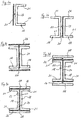
Fig. 1 in einer perspektivischen Explosionsdarstellung, und - Fig. 3a-3e
- die Herstellungsschritte zur Herstellung eines Trägers des Rahmens nach
Fig. 2 . - In dem in
Fig. 1 dargestellten Druckkörper 2 eines Unterseebootes ist ein Deck 4 angeordnet, das ein Fundament für eine Lagervorrichtung 6 bildet. Das Deck 4 ist in üblicher Weise mit der Wandung des Druckkörpers 2 starr verbunden. Die Lagervorrichtung 6 dient zur Lagerung von Aggregaten 8, die dort auf einer Lagerplattform 10 auf Gummifedern 12 elastisch gelagert aufgestellt sind. Die Lagerplattform 10 ist über Federelemente 14 elastisch auf dem Deck 4 gelagert. - Die Lagerplattform 10 weist eine Tragstruktur in Form eines rechteckigen Rahmens 16 auf (
Fig. 2 ). Bei dem Rahmen 16 sind zwei im Querschnitt u-förmige Träger 18, nachfolgend U-Träger genannt, und zwei U-Träger 20 über Schweißverbindungen zur Bildung eines starren Innenrahmens 22 zusammengefügt, wobei die Schenkel 21 der U-Träger 18 und 20 in das Innere des Rahmens 16 weisen. Alle verwendeten U-Träger 18 und 20 sind aus Stahl ausgebildet. - Wie in
Fig. 2 exemplarisch an einem der U-Träger 18 und insbesondere in denFig. 3a bis 3e dargestellt ist, werden an den Stegen 23 aller U-Träger 18 und 20 an der von den auskragenden Schenkeln 21 abgewandten Flachseite Klebebänder 24 verklebt. Bei den Klebebändern 24 handelt es sich um doppelseitig klebende Klebebänder 24, deren Trägermaterial viskoelastische Eigenschaften aufweist. An den von den U-Trägern 18 und 20 abgewandten Seiten der an den U-Trägern 18 und 20 befestigten Klebebänder 24 wird jeweils ein weiterer U-Träger 18 bzw. 20 verklebt. Die so miteinander verbundenen U-Träger 18 und 20 weisen miteinander korrespondierende Abmessungen auf. - An den Außenseiten der Schenkel 21 der miteinander über das Klebeband 24 verbundenen U-Träger 18 und 20 wird jeweils ein weiteres doppelseitig klebendes Klebeband 26 angebracht. Auch das Trägermaterial des Klebebands 26 weist viskoelastische Eigenschaften auf. Über das Klebeband 26 sind flache Leisten 28, die wie die U-Träger 18 und 20 aus Stahl ausgebildet sind, an den U-Trägern 18 und 20 befestigt.
- Gemeinsam bilden die miteinander verbunden U-Träger 18 und 20 sowie die Leisten 28 Trägerelemente des Rahmens 16 mit einem Doppel-T-Profil. Die von den Klebebändern 24 und 26 zwischen benachbarten Lagerteilen, d.h. den U-Trägern 18 und 20 sowie den Leisten 28 gebildeten viskoelastischen Schichten verleihen der Lagerplattform 10 eine innere Dämpfung, die bei einer Eigenschwingungserregung der Lagerplattform 10 die Entwicklung von Körperschall und eine Übertragung des Körperschalls auf den Druckkörper 2 des Unterseeboots behindert und bestenfalls verhindert.
-
- 2 -
- Druckkörper
- 4 -
- Deck
- 6 -
- Lagervorrichtung
- 8 -
- Aggregat
- 10 -
- Lagerplattform
- 12 -
- Gummifeder
- 14 -
- Federelement
- 16 -
- Rahmen
- 18 -
- U-Träger
- 20 -
- U-Träger
- 21 -
- Schenkel
- 22 -
- Innenrahmen
- 23 -
- Steg
- 24 -
- Klebeband
- 26 -
- Klebeband
- 28 -
- Leiste
Claims (10)
- Lagerplattform (10) zum Lagern mindestens eines Aggregats (8) in einem Unterseeboot gekennzeichnet durch mindestens zwei mittels einer viskoelastischen Schicht verbundene Lagerteile.
- Lagerplattform (10) nach Anspruch 1, dadurch gekennzeichnet, dass die viskoelastische Schicht in einer Haupterstreckungsrichtung der Lagerteile ausgerichtet vorzugsweise zwischen zwei Flachseiten der Lagerteile angeordnet ist.
- Lagerplattform (10) nach einem der vorangehenden Ansprüche, dadurch gekennzeichnet, dass ein viskoelastisches Material zwischen den Lagerteilen vergossen ist.
- Lagerplattform (10) nach einem der Ansprüche 1 oder 2, dadurch gekennzeichnet, dass die Lagerteile mit einem Klebeband (24, 26) mit viskoelastischen Eigenschaften miteinander verklebt sind.
- Lagerplattform (10) nach einem der vorangehenden Ansprüche, dadurch gekennzeichnet, dass die Lagerplattform (10) eine Tragstruktur aufweist, deren Träger aus zumindest paarweise angeordneten eigensteifen Profilelementen ausgebildet sind, welche mit einer viskoelastischen Schicht verbunden sind.
- Lagerplattform (10) nach Anspruch 5, dadurch gekennzeichnet, dass die Tragstruktur ein Rahmen (16) ist.
- Lagerplattform (10) nach Anspruch 6, dadurch gekennzeichnet, dass der Rahmen (16) einen Innenrahmen (22) aus miteinander verbundenen U-Trägern (18, 20) aufweist, deren Schenkel (21) in das Innere des Rahmens (16) gerichtet sind.
- Lagerplattform (10) nach Anspruch 7, dadurch gekennzeichnet, dass an den Außenseiten der Stege (23) der den Innenrahmen (22) bildenden U-Träger (18, 20) weitere U-Träger (18, 20) zur Bildung eines Doppel-T-Profils über das viskoelastische Material befestigt sind.
- Lagerplattform nach Anspruch 8, dadurch gekennzeichnet, dass an den Außenseiten der Schenkel (21) der U-Träger (18, 20) Leisten (28) über das viskoelastische Material befestigt sind.
- Unterseeboot mit einer elastisch auf einem mit dem Druckkörper starr verbundenen Fundament elastisch aufgestellten Lagervorrichtung (6), dadurch gekennzeichnet, dass die Lagervorrichtung (6) eine Lagerplattform (10) nach den vorangehenden Ansprüchen aufweist.
Applications Claiming Priority (1)
| Application Number | Priority Date | Filing Date | Title |
|---|---|---|---|
| DE102010034145A DE102010034145B3 (de) | 2010-08-12 | 2010-08-12 | Lagerplattform zum Lagern mindestens eines Aggregats in einem Unterseeboot |
Publications (2)
| Publication Number | Publication Date |
|---|---|
| EP2418144A1 true EP2418144A1 (de) | 2012-02-15 |
| EP2418144B1 EP2418144B1 (de) | 2016-07-20 |
Family
ID=44545560
Family Applications (1)
| Application Number | Title | Priority Date | Filing Date |
|---|---|---|---|
| EP11177160.6A Active EP2418144B1 (de) | 2010-08-12 | 2011-08-10 | Lagerplattform zum Lagern mindestens eines Aggregats in einem Unterseeboot |
Country Status (4)
| Country | Link |
|---|---|
| EP (1) | EP2418144B1 (de) |
| KR (1) | KR101288981B1 (de) |
| DE (1) | DE102010034145B3 (de) |
| ES (1) | ES2598036T3 (de) |
Cited By (3)
| Publication number | Priority date | Publication date | Assignee | Title |
|---|---|---|---|---|
| CN104364153A (zh) * | 2012-06-04 | 2015-02-18 | 卡特彼勒发动机有限及两合公司 | 阻尼发动机支架 |
| US9194469B2 (en) * | 2013-08-22 | 2015-11-24 | Danfoss Power Solutions Inc. | Bearing assembly for isolating and damping swashplate vibration |
| CN109911114A (zh) * | 2019-03-08 | 2019-06-21 | 大连海事大学 | 一种具有三级减震自稳系统的无人船 |
Families Citing this family (1)
| Publication number | Priority date | Publication date | Assignee | Title |
|---|---|---|---|---|
| KR101896784B1 (ko) * | 2016-10-17 | 2018-09-10 | (주)한국해사기술 | 잠수함의 이중탄성마운트용 플랫폼 구조 |
Citations (9)
| Publication number | Priority date | Publication date | Assignee | Title |
|---|---|---|---|---|
| DE2425419A1 (de) * | 1974-05-25 | 1975-12-04 | Rohdjess Joachim | Vorrichtung zur lagerung von bauteilen in einer tragenden konstruktion insbesondere in fahrzeugen |
| DE4208889A1 (de) * | 1992-03-19 | 1993-09-23 | Atlas Elektronik Gmbh | Koerperschalldaempfendes verbundsystem |
| WO1993021402A1 (en) * | 1992-04-08 | 1993-10-28 | Ecomax Acoustics Ltd. | Building element and method of manufacturing such element |
| DE10212075A1 (de) * | 2002-03-19 | 2003-10-09 | Nordseewerke Gmbh | Vorrichtung zur Lagerung von Antrieben |
| EP1366984A1 (de) * | 2002-05-29 | 2003-12-03 | Siemens Aktiengesellschaft | Schwingungsdämpfungsvorrichtung für Antriebsaggregate von Schiffsantriebsanlagen von Über- und Unterwasserschiffen |
| EP1447324A1 (de) * | 2003-02-12 | 2004-08-18 | Howaldtswerke-Deutsche Werft Ag | Unterseeboot mit einem Schalldämpfungssystem |
| DE10357226B3 (de) * | 2003-12-08 | 2005-03-24 | Howaldtswerke - Deutsche Werft Ag | Lagerungseinheit |
| WO2005036015A1 (en) * | 2003-10-09 | 2005-04-21 | Trelleborg Ab (Publ) | Vibration mounting |
| EP1847456A2 (de) * | 2006-04-20 | 2007-10-24 | Nordseewerke GmbH | Lagerplattform zur Aufnahme schwingungenerzeugende Aggregate für Marineschiffe |
Family Cites Families (1)
| Publication number | Priority date | Publication date | Assignee | Title |
|---|---|---|---|---|
| US5108802A (en) * | 1990-01-09 | 1992-04-28 | Westinghouse Electric Corp. | Internally damped thin-walled, composite longitudinal member having dedicated internal constraining layers |
-
2010
- 2010-08-12 DE DE102010034145A patent/DE102010034145B3/de active Active
-
2011
- 2011-07-21 KR KR1020110072577A patent/KR101288981B1/ko active Active
- 2011-08-10 EP EP11177160.6A patent/EP2418144B1/de active Active
- 2011-08-10 ES ES11177160.6T patent/ES2598036T3/es active Active
Patent Citations (9)
| Publication number | Priority date | Publication date | Assignee | Title |
|---|---|---|---|---|
| DE2425419A1 (de) * | 1974-05-25 | 1975-12-04 | Rohdjess Joachim | Vorrichtung zur lagerung von bauteilen in einer tragenden konstruktion insbesondere in fahrzeugen |
| DE4208889A1 (de) * | 1992-03-19 | 1993-09-23 | Atlas Elektronik Gmbh | Koerperschalldaempfendes verbundsystem |
| WO1993021402A1 (en) * | 1992-04-08 | 1993-10-28 | Ecomax Acoustics Ltd. | Building element and method of manufacturing such element |
| DE10212075A1 (de) * | 2002-03-19 | 2003-10-09 | Nordseewerke Gmbh | Vorrichtung zur Lagerung von Antrieben |
| EP1366984A1 (de) * | 2002-05-29 | 2003-12-03 | Siemens Aktiengesellschaft | Schwingungsdämpfungsvorrichtung für Antriebsaggregate von Schiffsantriebsanlagen von Über- und Unterwasserschiffen |
| EP1447324A1 (de) * | 2003-02-12 | 2004-08-18 | Howaldtswerke-Deutsche Werft Ag | Unterseeboot mit einem Schalldämpfungssystem |
| WO2005036015A1 (en) * | 2003-10-09 | 2005-04-21 | Trelleborg Ab (Publ) | Vibration mounting |
| DE10357226B3 (de) * | 2003-12-08 | 2005-03-24 | Howaldtswerke - Deutsche Werft Ag | Lagerungseinheit |
| EP1847456A2 (de) * | 2006-04-20 | 2007-10-24 | Nordseewerke GmbH | Lagerplattform zur Aufnahme schwingungenerzeugende Aggregate für Marineschiffe |
Cited By (4)
| Publication number | Priority date | Publication date | Assignee | Title |
|---|---|---|---|---|
| CN104364153A (zh) * | 2012-06-04 | 2015-02-18 | 卡特彼勒发动机有限及两合公司 | 阻尼发动机支架 |
| US9194469B2 (en) * | 2013-08-22 | 2015-11-24 | Danfoss Power Solutions Inc. | Bearing assembly for isolating and damping swashplate vibration |
| CN109911114A (zh) * | 2019-03-08 | 2019-06-21 | 大连海事大学 | 一种具有三级减震自稳系统的无人船 |
| CN109911114B (zh) * | 2019-03-08 | 2020-09-22 | 大连海事大学 | 一种具有三级减震自稳系统的无人船 |
Also Published As
| Publication number | Publication date |
|---|---|
| KR20120016002A (ko) | 2012-02-22 |
| EP2418144B1 (de) | 2016-07-20 |
| ES2598036T3 (es) | 2017-01-24 |
| DE102010034145B3 (de) | 2011-12-22 |
| KR101288981B1 (ko) | 2013-07-22 |
Similar Documents
| Publication | Publication Date | Title |
|---|---|---|
| DE2360857C2 (de) | Elastisches Lager, insbesondere Motorlager | |
| DE60003585T2 (de) | Strukturell laminierte platten mit metallischen aussenschichten und einer elastomerzwischenschicht | |
| EP2595877B1 (de) | Strukturbauteil mit zumindest einer hauptlast-tragenden beplankungsschale und einer trägerstruktur zur befestigung der hauptlast-tragenden beplankungsschale sowie strömungskörper mit einem solchen strukturbauteil | |
| DE102007036670B4 (de) | Bausatz zum Aufbau eines Fußbodens für ein Schienenfahrzeug | |
| DE1126684B (de) | Einrichtung zur Daempfung der Biegebewegungen einer Flaeche | |
| EP2418144B1 (de) | Lagerplattform zum Lagern mindestens eines Aggregats in einem Unterseeboot | |
| DE202017104578U1 (de) | Elastisches Element für einen Befestigungspunkt für eine Schiene für Schienenfahrzeuge und Befestigungspunkt | |
| EP1004538A1 (de) | Hochsteifer Aufzugs-Kabinenboden | |
| DE102014113145A1 (de) | Lärmschutzwand | |
| EP1917185B1 (de) | Schalldämmelement für verkehrsmittel, insbesondere für luftfahrzeuge | |
| EP1409791B1 (de) | Pneumatisches bau- oder brückenelement | |
| DE102013003080A1 (de) | Strukturell gefügte Längsträger aufweisender Dachträger eines Kraftfahrzeugs | |
| EP2436594B1 (de) | Unterseeboot | |
| DE102011106277B4 (de) | Lärmschutzfeld | |
| DE102017008181A1 (de) | Lärmschutzelement | |
| DE102012010465A1 (de) | Rohbaustruktur für einen Rohbau eines Kraftfahrzeugs | |
| DE102014200671A1 (de) | Tragstruktur für ein Kraftfahrzeug, Achsträger und Fahrzeug mit einer Tragstruktur | |
| DE1162137B (de) | Vorgefertigtes lastaufnehmendes Bauelement fuer Bauwerke, Maschinen, Geraete od. dgl. | |
| DE202009011263U1 (de) | Vorrichtung zum Schutz eines Schiffsrumpfes gegen Einflüsse von Schockwellen | |
| DE202015106420U1 (de) | Modulare Plattform | |
| DE102005022868A1 (de) | Einlage für Rückhaltewand auf Stück- und Massengutaufbauten für Land- und Wasserfahrzeuge | |
| DE202011110383U1 (de) | Lärmschutzfeld | |
| AT527290B1 (de) | Lager zur Anordnung zwischen zwei tragenden Bauteilen | |
| DE102019121370A1 (de) | Fußbodenaufbau, insbesondere für ein Schienenfahrzeug, und Schienenfahrzeug mit mindestens einem Fußbodenaufbau | |
| DE202018104035U1 (de) | Akustisches Bauteil |
Legal Events
| Date | Code | Title | Description |
|---|---|---|---|
| AK | Designated contracting states |
Kind code of ref document: A1 Designated state(s): AL AT BE BG CH CY CZ DE DK EE ES FI FR GB GR HR HU IE IS IT LI LT LU LV MC MK MT NL NO PL PT RO RS SE SI SK SM TR |
|
| AX | Request for extension of the european patent |
Extension state: BA ME |
|
| PUAI | Public reference made under article 153(3) epc to a published international application that has entered the european phase |
Free format text: ORIGINAL CODE: 0009012 |
|
| 17P | Request for examination filed |
Effective date: 20120221 |
|
| RAP1 | Party data changed (applicant data changed or rights of an application transferred) |
Owner name: THYSSENKRUPP MARINE SYSTEMS GMBH |
|
| 17Q | First examination report despatched |
Effective date: 20140808 |
|
| RIC1 | Information provided on ipc code assigned before grant |
Ipc: B63G 13/02 20060101ALI20160112BHEP Ipc: F16F 15/08 20060101ALI20160112BHEP Ipc: F16F 9/30 20060101ALI20160112BHEP Ipc: B63G 8/34 20060101AFI20160112BHEP Ipc: B63H 21/30 20060101ALI20160112BHEP |
|
| GRAP | Despatch of communication of intention to grant a patent |
Free format text: ORIGINAL CODE: EPIDOSNIGR1 |
|
| INTG | Intention to grant announced |
Effective date: 20160223 |
|
| RBV | Designated contracting states (corrected) |
Designated state(s): AL AT BE BG CH CY CZ DK EE ES FI FR GB GR HR HU IE IS IT LI LT LU LV MC MK MT NL NO PL PT RO RS SE SI SK SM TR |
|
| REG | Reference to a national code |
Ref country code: DE Ref legal event code: R108 |
|
| GRAS | Grant fee paid |
Free format text: ORIGINAL CODE: EPIDOSNIGR3 |
|
| GRAA | (expected) grant |
Free format text: ORIGINAL CODE: 0009210 |
|
| AK | Designated contracting states |
Kind code of ref document: B1 Designated state(s): AL AT BE BG CH CY CZ DK EE ES FI FR GB GR HR HU IE IS IT LI LT LU LV MC MK MT NL NO PL PT RO RS SE SI SK SM TR |
|
| REG | Reference to a national code |
Ref country code: GB Ref legal event code: FG4D Free format text: NOT ENGLISH |
|
| REG | Reference to a national code |
Ref country code: CH Ref legal event code: EP |
|
| REG | Reference to a national code |
Ref country code: IE Ref legal event code: FG4D Free format text: LANGUAGE OF EP DOCUMENT: GERMAN |
|
| REG | Reference to a national code |
Ref country code: AT Ref legal event code: REF Ref document number: 813822 Country of ref document: AT Kind code of ref document: T Effective date: 20160815 |
|
| REG | Reference to a national code |
Ref country code: FR Ref legal event code: PLFP Year of fee payment: 6 |
|
| REG | Reference to a national code |
Ref country code: SE Ref legal event code: TRGR |
|
| REG | Reference to a national code |
Ref country code: LT Ref legal event code: MG4D |
|
| REG | Reference to a national code |
Ref country code: NL Ref legal event code: MP Effective date: 20160720 |
|
| PG25 | Lapsed in a contracting state [announced via postgrant information from national office to epo] |
Ref country code: BE Free format text: LAPSE BECAUSE OF NON-PAYMENT OF DUE FEES Effective date: 20160831 |
|
| REG | Reference to a national code |
Ref country code: ES Ref legal event code: FG2A Ref document number: 2598036 Country of ref document: ES Kind code of ref document: T3 Effective date: 20170124 |
|
| PG25 | Lapsed in a contracting state [announced via postgrant information from national office to epo] |
Ref country code: HR Free format text: LAPSE BECAUSE OF FAILURE TO SUBMIT A TRANSLATION OF THE DESCRIPTION OR TO PAY THE FEE WITHIN THE PRESCRIBED TIME-LIMIT Effective date: 20160720 Ref country code: LT Free format text: LAPSE BECAUSE OF FAILURE TO SUBMIT A TRANSLATION OF THE DESCRIPTION OR TO PAY THE FEE WITHIN THE PRESCRIBED TIME-LIMIT Effective date: 20160720 Ref country code: NO Free format text: LAPSE BECAUSE OF FAILURE TO SUBMIT A TRANSLATION OF THE DESCRIPTION OR TO PAY THE FEE WITHIN THE PRESCRIBED TIME-LIMIT Effective date: 20161020 Ref country code: IS Free format text: LAPSE BECAUSE OF FAILURE TO SUBMIT A TRANSLATION OF THE DESCRIPTION OR TO PAY THE FEE WITHIN THE PRESCRIBED TIME-LIMIT Effective date: 20161120 Ref country code: RS Free format text: LAPSE BECAUSE OF FAILURE TO SUBMIT A TRANSLATION OF THE DESCRIPTION OR TO PAY THE FEE WITHIN THE PRESCRIBED TIME-LIMIT Effective date: 20160720 Ref country code: NL Free format text: LAPSE BECAUSE OF FAILURE TO SUBMIT A TRANSLATION OF THE DESCRIPTION OR TO PAY THE FEE WITHIN THE PRESCRIBED TIME-LIMIT Effective date: 20160720 Ref country code: FI Free format text: LAPSE BECAUSE OF FAILURE TO SUBMIT A TRANSLATION OF THE DESCRIPTION OR TO PAY THE FEE WITHIN THE PRESCRIBED TIME-LIMIT Effective date: 20160720 |
|
| PG25 | Lapsed in a contracting state [announced via postgrant information from national office to epo] |
Ref country code: PT Free format text: LAPSE BECAUSE OF FAILURE TO SUBMIT A TRANSLATION OF THE DESCRIPTION OR TO PAY THE FEE WITHIN THE PRESCRIBED TIME-LIMIT Effective date: 20161121 Ref country code: PL Free format text: LAPSE BECAUSE OF FAILURE TO SUBMIT A TRANSLATION OF THE DESCRIPTION OR TO PAY THE FEE WITHIN THE PRESCRIBED TIME-LIMIT Effective date: 20160720 Ref country code: GR Free format text: LAPSE BECAUSE OF FAILURE TO SUBMIT A TRANSLATION OF THE DESCRIPTION OR TO PAY THE FEE WITHIN THE PRESCRIBED TIME-LIMIT Effective date: 20161021 Ref country code: LV Free format text: LAPSE BECAUSE OF FAILURE TO SUBMIT A TRANSLATION OF THE DESCRIPTION OR TO PAY THE FEE WITHIN THE PRESCRIBED TIME-LIMIT Effective date: 20160720 |
|
| REG | Reference to a national code |
Ref country code: CH Ref legal event code: PL |
|
| PG25 | Lapsed in a contracting state [announced via postgrant information from national office to epo] |
Ref country code: LI Free format text: LAPSE BECAUSE OF NON-PAYMENT OF DUE FEES Effective date: 20160831 Ref country code: EE Free format text: LAPSE BECAUSE OF FAILURE TO SUBMIT A TRANSLATION OF THE DESCRIPTION OR TO PAY THE FEE WITHIN THE PRESCRIBED TIME-LIMIT Effective date: 20160720 Ref country code: RO Free format text: LAPSE BECAUSE OF FAILURE TO SUBMIT A TRANSLATION OF THE DESCRIPTION OR TO PAY THE FEE WITHIN THE PRESCRIBED TIME-LIMIT Effective date: 20160720 Ref country code: CH Free format text: LAPSE BECAUSE OF NON-PAYMENT OF DUE FEES Effective date: 20160831 Ref country code: MC Free format text: LAPSE BECAUSE OF FAILURE TO SUBMIT A TRANSLATION OF THE DESCRIPTION OR TO PAY THE FEE WITHIN THE PRESCRIBED TIME-LIMIT Effective date: 20160720 |
|
| PLBE | No opposition filed within time limit |
Free format text: ORIGINAL CODE: 0009261 |
|
| STAA | Information on the status of an ep patent application or granted ep patent |
Free format text: STATUS: NO OPPOSITION FILED WITHIN TIME LIMIT |
|
| PG25 | Lapsed in a contracting state [announced via postgrant information from national office to epo] |
Ref country code: SK Free format text: LAPSE BECAUSE OF FAILURE TO SUBMIT A TRANSLATION OF THE DESCRIPTION OR TO PAY THE FEE WITHIN THE PRESCRIBED TIME-LIMIT Effective date: 20160720 Ref country code: SM Free format text: LAPSE BECAUSE OF FAILURE TO SUBMIT A TRANSLATION OF THE DESCRIPTION OR TO PAY THE FEE WITHIN THE PRESCRIBED TIME-LIMIT Effective date: 20160720 Ref country code: BG Free format text: LAPSE BECAUSE OF FAILURE TO SUBMIT A TRANSLATION OF THE DESCRIPTION OR TO PAY THE FEE WITHIN THE PRESCRIBED TIME-LIMIT Effective date: 20161020 Ref country code: DK Free format text: LAPSE BECAUSE OF FAILURE TO SUBMIT A TRANSLATION OF THE DESCRIPTION OR TO PAY THE FEE WITHIN THE PRESCRIBED TIME-LIMIT Effective date: 20160720 Ref country code: CZ Free format text: LAPSE BECAUSE OF FAILURE TO SUBMIT A TRANSLATION OF THE DESCRIPTION OR TO PAY THE FEE WITHIN THE PRESCRIBED TIME-LIMIT Effective date: 20160720 |
|
| REG | Reference to a national code |
Ref country code: IE Ref legal event code: MM4A |
|
| 26N | No opposition filed |
Effective date: 20170421 |
|
| PG25 | Lapsed in a contracting state [announced via postgrant information from national office to epo] |
Ref country code: IE Free format text: LAPSE BECAUSE OF NON-PAYMENT OF DUE FEES Effective date: 20160810 |
|
| REG | Reference to a national code |
Ref country code: FR Ref legal event code: PLFP Year of fee payment: 7 |
|
| PG25 | Lapsed in a contracting state [announced via postgrant information from national office to epo] |
Ref country code: SI Free format text: LAPSE BECAUSE OF FAILURE TO SUBMIT A TRANSLATION OF THE DESCRIPTION OR TO PAY THE FEE WITHIN THE PRESCRIBED TIME-LIMIT Effective date: 20160720 Ref country code: LU Free format text: LAPSE BECAUSE OF NON-PAYMENT OF DUE FEES Effective date: 20160810 |
|
| REG | Reference to a national code |
Ref country code: AT Ref legal event code: MM01 Ref document number: 813822 Country of ref document: AT Kind code of ref document: T Effective date: 20160810 |
|
| PG25 | Lapsed in a contracting state [announced via postgrant information from national office to epo] |
Ref country code: AT Free format text: LAPSE BECAUSE OF NON-PAYMENT OF DUE FEES Effective date: 20160810 |
|
| PG25 | Lapsed in a contracting state [announced via postgrant information from national office to epo] |
Ref country code: CY Free format text: LAPSE BECAUSE OF FAILURE TO SUBMIT A TRANSLATION OF THE DESCRIPTION OR TO PAY THE FEE WITHIN THE PRESCRIBED TIME-LIMIT Effective date: 20160720 Ref country code: HU Free format text: LAPSE BECAUSE OF FAILURE TO SUBMIT A TRANSLATION OF THE DESCRIPTION OR TO PAY THE FEE WITHIN THE PRESCRIBED TIME-LIMIT; INVALID AB INITIO Effective date: 20110810 |
|
| PG25 | Lapsed in a contracting state [announced via postgrant information from national office to epo] |
Ref country code: MK Free format text: LAPSE BECAUSE OF FAILURE TO SUBMIT A TRANSLATION OF THE DESCRIPTION OR TO PAY THE FEE WITHIN THE PRESCRIBED TIME-LIMIT Effective date: 20160720 Ref country code: MT Free format text: LAPSE BECAUSE OF FAILURE TO SUBMIT A TRANSLATION OF THE DESCRIPTION OR TO PAY THE FEE WITHIN THE PRESCRIBED TIME-LIMIT Effective date: 20160720 |
|
| REG | Reference to a national code |
Ref country code: FR Ref legal event code: PLFP Year of fee payment: 8 |
|
| PG25 | Lapsed in a contracting state [announced via postgrant information from national office to epo] |
Ref country code: AL Free format text: LAPSE BECAUSE OF FAILURE TO SUBMIT A TRANSLATION OF THE DESCRIPTION OR TO PAY THE FEE WITHIN THE PRESCRIBED TIME-LIMIT Effective date: 20160720 |
|
| PGFP | Annual fee paid to national office [announced via postgrant information from national office to epo] |
Ref country code: ES Payment date: 20250925 Year of fee payment: 15 |
|
| PGFP | Annual fee paid to national office [announced via postgrant information from national office to epo] |
Ref country code: TR Payment date: 20250804 Year of fee payment: 15 Ref country code: IT Payment date: 20250825 Year of fee payment: 15 |
|
| PGFP | Annual fee paid to national office [announced via postgrant information from national office to epo] |
Ref country code: GB Payment date: 20250820 Year of fee payment: 15 |
|
| PGFP | Annual fee paid to national office [announced via postgrant information from national office to epo] |
Ref country code: FR Payment date: 20250829 Year of fee payment: 15 |
|
| PGFP | Annual fee paid to national office [announced via postgrant information from national office to epo] |
Ref country code: SE Payment date: 20250820 Year of fee payment: 15 |