EP2418141A1 - Shaft coupling structure - Google Patents
Shaft coupling structure Download PDFInfo
- Publication number
- EP2418141A1 EP2418141A1 EP09843045A EP09843045A EP2418141A1 EP 2418141 A1 EP2418141 A1 EP 2418141A1 EP 09843045 A EP09843045 A EP 09843045A EP 09843045 A EP09843045 A EP 09843045A EP 2418141 A1 EP2418141 A1 EP 2418141A1
- Authority
- EP
- European Patent Office
- Prior art keywords
- shaft
- bolt
- tightened
- coupling member
- aperture
- Prior art date
- Legal status (The legal status is an assumption and is not a legal conclusion. Google has not performed a legal analysis and makes no representation as to the accuracy of the status listed.)
- Granted
Links
Images


Classifications
-
- B—PERFORMING OPERATIONS; TRANSPORTING
- B62—LAND VEHICLES FOR TRAVELLING OTHERWISE THAN ON RAILS
- B62D—MOTOR VEHICLES; TRAILERS
- B62D1/00—Steering controls, i.e. means for initiating a change of direction of the vehicle
- B62D1/02—Steering controls, i.e. means for initiating a change of direction of the vehicle vehicle-mounted
- B62D1/16—Steering columns
-
- B—PERFORMING OPERATIONS; TRANSPORTING
- B62—LAND VEHICLES FOR TRAVELLING OTHERWISE THAN ON RAILS
- B62D—MOTOR VEHICLES; TRAILERS
- B62D1/00—Steering controls, i.e. means for initiating a change of direction of the vehicle
- B62D1/02—Steering controls, i.e. means for initiating a change of direction of the vehicle vehicle-mounted
- B62D1/16—Steering columns
- B62D1/20—Connecting steering column to steering gear
-
- F—MECHANICAL ENGINEERING; LIGHTING; HEATING; WEAPONS; BLASTING
- F16—ENGINEERING ELEMENTS AND UNITS; GENERAL MEASURES FOR PRODUCING AND MAINTAINING EFFECTIVE FUNCTIONING OF MACHINES OR INSTALLATIONS; THERMAL INSULATION IN GENERAL
- F16D—COUPLINGS FOR TRANSMITTING ROTATION; CLUTCHES; BRAKES
- F16D1/00—Couplings for rigidly connecting two coaxial shafts or other movable machine elements
- F16D1/06—Couplings for rigidly connecting two coaxial shafts or other movable machine elements for attachment of a member on a shaft or on a shaft-end
- F16D1/08—Couplings for rigidly connecting two coaxial shafts or other movable machine elements for attachment of a member on a shaft or on a shaft-end with clamping hub; with hub and longitudinal key
- F16D1/0852—Couplings for rigidly connecting two coaxial shafts or other movable machine elements for attachment of a member on a shaft or on a shaft-end with clamping hub; with hub and longitudinal key with radial clamping between the mating surfaces of the hub and shaft
- F16D1/0864—Couplings for rigidly connecting two coaxial shafts or other movable machine elements for attachment of a member on a shaft or on a shaft-end with clamping hub; with hub and longitudinal key with radial clamping between the mating surfaces of the hub and shaft due to tangential loading of the hub, e.g. a split hub
-
- F—MECHANICAL ENGINEERING; LIGHTING; HEATING; WEAPONS; BLASTING
- F16—ENGINEERING ELEMENTS AND UNITS; GENERAL MEASURES FOR PRODUCING AND MAINTAINING EFFECTIVE FUNCTIONING OF MACHINES OR INSTALLATIONS; THERMAL INSULATION IN GENERAL
- F16D—COUPLINGS FOR TRANSMITTING ROTATION; CLUTCHES; BRAKES
- F16D1/00—Couplings for rigidly connecting two coaxial shafts or other movable machine elements
- F16D1/06—Couplings for rigidly connecting two coaxial shafts or other movable machine elements for attachment of a member on a shaft or on a shaft-end
- F16D1/08—Couplings for rigidly connecting two coaxial shafts or other movable machine elements for attachment of a member on a shaft or on a shaft-end with clamping hub; with hub and longitudinal key
- F16D1/0894—Couplings for rigidly connecting two coaxial shafts or other movable machine elements for attachment of a member on a shaft or on a shaft-end with clamping hub; with hub and longitudinal key with other than axial keys, e.g. diametral pins, cotter pins and no other radial clamping
-
- F—MECHANICAL ENGINEERING; LIGHTING; HEATING; WEAPONS; BLASTING
- F16—ENGINEERING ELEMENTS AND UNITS; GENERAL MEASURES FOR PRODUCING AND MAINTAINING EFFECTIVE FUNCTIONING OF MACHINES OR INSTALLATIONS; THERMAL INSULATION IN GENERAL
- F16D—COUPLINGS FOR TRANSMITTING ROTATION; CLUTCHES; BRAKES
- F16D1/00—Couplings for rigidly connecting two coaxial shafts or other movable machine elements
- F16D1/10—Quick-acting couplings in which the parts are connected by simply bringing them together axially
- F16D1/108—Quick-acting couplings in which the parts are connected by simply bringing them together axially having retaining means rotating with the coupling and acting by interengaging parts, i.e. positive coupling
- F16D1/116—Quick-acting couplings in which the parts are connected by simply bringing them together axially having retaining means rotating with the coupling and acting by interengaging parts, i.e. positive coupling the interengaging parts including a continuous or interrupted circumferential groove in the surface of one of the coupling parts
-
- F—MECHANICAL ENGINEERING; LIGHTING; HEATING; WEAPONS; BLASTING
- F16—ENGINEERING ELEMENTS AND UNITS; GENERAL MEASURES FOR PRODUCING AND MAINTAINING EFFECTIVE FUNCTIONING OF MACHINES OR INSTALLATIONS; THERMAL INSULATION IN GENERAL
- F16D—COUPLINGS FOR TRANSMITTING ROTATION; CLUTCHES; BRAKES
- F16D3/00—Yielding couplings, i.e. with means permitting movement between the connected parts during the drive
- F16D3/16—Universal joints in which flexibility is produced by means of pivots or sliding or rolling connecting parts
- F16D3/26—Hooke's joints or other joints with an equivalent intermediate member to which each coupling part is pivotally or slidably connected
- F16D3/38—Hooke's joints or other joints with an equivalent intermediate member to which each coupling part is pivotally or slidably connected with a single intermediate member with trunnions or bearings arranged on two axes perpendicular to one another
- F16D3/382—Hooke's joints or other joints with an equivalent intermediate member to which each coupling part is pivotally or slidably connected with a single intermediate member with trunnions or bearings arranged on two axes perpendicular to one another constructional details of other than the intermediate member
- F16D3/387—Fork construction; Mounting of fork on shaft; Adapting shaft for mounting of fork
-
- F—MECHANICAL ENGINEERING; LIGHTING; HEATING; WEAPONS; BLASTING
- F16—ENGINEERING ELEMENTS AND UNITS; GENERAL MEASURES FOR PRODUCING AND MAINTAINING EFFECTIVE FUNCTIONING OF MACHINES OR INSTALLATIONS; THERMAL INSULATION IN GENERAL
- F16B—DEVICES FOR FASTENING OR SECURING CONSTRUCTIONAL ELEMENTS OR MACHINE PARTS TOGETHER, e.g. NAILS, BOLTS, CIRCLIPS, CLAMPS, CLIPS OR WEDGES; JOINTS OR JOINTING
- F16B2200/00—Constructional details of connections not covered for in other groups of this subclass
- F16B2200/69—Redundant disconnection blocking means
-
- F—MECHANICAL ENGINEERING; LIGHTING; HEATING; WEAPONS; BLASTING
- F16—ENGINEERING ELEMENTS AND UNITS; GENERAL MEASURES FOR PRODUCING AND MAINTAINING EFFECTIVE FUNCTIONING OF MACHINES OR INSTALLATIONS; THERMAL INSULATION IN GENERAL
- F16D—COUPLINGS FOR TRANSMITTING ROTATION; CLUTCHES; BRAKES
- F16D1/00—Couplings for rigidly connecting two coaxial shafts or other movable machine elements
- F16D1/10—Quick-acting couplings in which the parts are connected by simply bringing them together axially
- F16D2001/103—Quick-acting couplings in which the parts are connected by simply bringing them together axially the torque is transmitted via splined connections
-
- Y—GENERAL TAGGING OF NEW TECHNOLOGICAL DEVELOPMENTS; GENERAL TAGGING OF CROSS-SECTIONAL TECHNOLOGIES SPANNING OVER SEVERAL SECTIONS OF THE IPC; TECHNICAL SUBJECTS COVERED BY FORMER USPC CROSS-REFERENCE ART COLLECTIONS [XRACs] AND DIGESTS
- Y10—TECHNICAL SUBJECTS COVERED BY FORMER USPC
- Y10T—TECHNICAL SUBJECTS COVERED BY FORMER US CLASSIFICATION
- Y10T403/00—Joints and connections
- Y10T403/70—Interfitted members
- Y10T403/7018—Interfitted members including separably interposed key
-
- Y—GENERAL TAGGING OF NEW TECHNOLOGICAL DEVELOPMENTS; GENERAL TAGGING OF CROSS-SECTIONAL TECHNOLOGIES SPANNING OVER SEVERAL SECTIONS OF THE IPC; TECHNICAL SUBJECTS COVERED BY FORMER USPC CROSS-REFERENCE ART COLLECTIONS [XRACs] AND DIGESTS
- Y10—TECHNICAL SUBJECTS COVERED BY FORMER USPC
- Y10T—TECHNICAL SUBJECTS COVERED BY FORMER US CLASSIFICATION
- Y10T403/00—Joints and connections
- Y10T403/70—Interfitted members
- Y10T403/7075—Interfitted members including discrete retainer
Definitions
- This invention relates to a shaft connection structure, for example, applied to a coupling part wherein a steering gear shaft and a coupling member of a steering device for a vehicle are coupled with each other.
- a shaft connection structure applied to a coupling part wherein a shaft and a coupling member of the steering device for the vehicle are coupled with each other is described, for example, in Unexamined Japanese Utility Model Publication No. 4-54325 .
- the shaft has a tightened shaft portion (generally, serrations are formed on its outer periphery) at its tip end portion, and an annular bolt engagement groove on the axially intermediate portion of the tightened shaft portion
- the coupling member has a tightened portion formed with a shaft insertion hole (generally, serrations are formed on its inner periphery), into which the tightened shaft portion of the shaft is inserted, and a bolt insertion aperture provided to cross a part of the shaft insertion hole at the tightened portion.
- the tightened shaft portion of the shaft and the tightened portion of the coupling member are coupled with each other such that a required torque can be transmitted therebetween by inserting the tightened shaft portion of the shaft into the shaft insertion hole of the coupling member, and inserting the bolt into the bolt insertion aperture of the coupling member and the bolt engagement groove of the shaft and tightening the bolt in the condition (the regular position condition) that the bolt engagement groove of the shaft and the bolt insertion aperture of the coupling member are axially aligned with each other.
- a shaft portion having a diameter smaller than that of the tightened shaft portion is integrally formed on the tip end of the tightened shaft portion of the shaft to have a predetermined length enough to block the bolt insertion aperture to prevent the insertion of the bolt through the bolt insertion aperture in the condition (the non-regular position condition) that the shaft portion axially overlaps the bolt insertion aperture of the coupling member when the tightened shaft portion of the shaft is inserted into the shaft insertion hole of the coupling member.
- the bolt cannot be inserted into the bolt insertion aperture, and therefore mis-assembling of the bolt (i.e. mis-assembling that the bolt is inserted into the bolt insertion aperture and is tightened thereto) can be prevented, and the shaft and the coupling member cannot be coupled with each other.
- the outer periphery of the shaft portion having the predetermined length and formed in the shaft and the inner periphery of the shaft insertion hole (serrations are formed on its inner periphery) formed in the coupling member may be frictionally engaged with each other, and therefore the shaft and the coupling member may be coupled with each other such that the required torque can be transmitted therebetween.
- the present invention is to solve the above-mentioned problem (to prevent the shaft and the coupling member from being coupled with each other such that the required torque can be transmitted therebetween in the non-regular position condition), and is a shaft connection structure, comprising: a shaft having a tightened shaft portion (generally, formed with serrations on its outer periphery) at its tip end portion and an annular bolt engagement groove on the axially intermediate portion of the tightened shaft portion; a coupling member having a tightened portion formed with a shaft insertion hole, (generally, serrations are formed on its inner periphery), into which the tightened shaft portion of the shaft can be inserted, and a bolt insertion aperture provided to cross a part of the shaft insertion hole at the tightened portion; and a bolt which is inserted into the bolt insertion aperture of the coupling member and is tightened thereto; wherein the tightened shaft portion of the shaft and the tightened portion of the coupling member are coupled with each other such that a required torque can be transmitted therebetween by
- the insertion restriction portion may be constituted as a member independently of the shaft, and may be coaxially assembled to the shaft by press-fitting. Further, the insertion restriction portion may be integrally formed on the shaft, and may be coaxially connected with the tip end of the tightened shaft portion via a low-strength shaft portion (for example, a small-diameter shaft portion). Further, the insertion restriction portion may be formed to have a cylindrical shape as a member independently of the shaft, and may be coaxially assembled to the shaft by a stepped bolt.
- the insertion restriction portion may be formed to have a cylindrical shape as a member independently of the shaft, may be rotatably fit onto a support shaft portion coaxially formed in the shaft, and may be prevented from being fallen out therefrom by swaging the tip end of the support shaft portion.
- the tightened shaft portion of the shaft and the tightened portion of the coupling member are coupled with each other such that the required torque can be transmitted therebetween by inserting the tightened shaft portion of the shaft into the shaft insertion hole of the coupling member, and inserting the bolt into the bolt insertion aperture of the coupling member and the bolt engagement groove of the shaft and tightening the bolt in the condition (the regular position condition) that the bolt engagement groove of the shaft and the bolt insertion aperture of the coupling member are axially aligned with each other.
- the insertion restriction portion having a diameter smaller than that of the tightened shaft portion is provided at the tip end of the tightened shaft portion of the shaft for restricting the insertion of the bolt through the bolt insertion aperture of the coupling member in the condition (the non-regular position condition) that the insertion restriction portion axially overlaps the bolt insertion aperture of the coupling member when the tightened shaft portion of the shaft is inserted into the shaft insertion hole of the coupling member. Accordingly, in the above-mentioned non-regular position condition, the bolt cannot be inserted into the bolt insertion aperture, and the mis-assembling of the bolt can be prevented and the coupling of the shaft and the coupling member with each other can be prevented.
- the shaft connection structure in the case that the bolt is inserted into the bolt insertion aperture of the coupling member and is tightened by a torque larger than or equal to a specified torque in the condition that the insertion restriction portion provided at the tip end of the shaft does not axially overlap the bolt insertion aperture of the coupling member (the condition that the amount of the insertion of the shaft into the shaft insertion hole is small) even when the insertion restriction portion is inserted into the shaft insertion hole of the coupling member, the outer periphery of the insertion restriction portion provided at the shaft and the inner periphery of the shaft insertion hole (generally, serrations are formed on its inner periphery) formed in the coupling member are frictionally engaged with each other, and therefore the insertion restriction portion provided at the shaft and the coupling member may be coupled with each other (mis-coupling) such that the required torque can be transmitted therebetween.
- the insertion restriction portion can be rotated relative to the shaft by the set torque smaller than the required torque, and therefore when the above-mentioned mis-coupling occurs, even when the insertion restriction portion provided at the shaft and the coupling member are coupled with each other such that the required torque can be transmitted therebetween, the insertion restriction portion is rotated relative to the shaft by the set torque smaller than the required torque. Accordingly, the above-mentioned mis-coupling can be detected on the basis of the relative rotation (for example, the offset of the steering neutral position in the steering device) between the shaft and the coupling member along with the rotation of the insertion restriction portion relative to the shaft.
- the relative rotation for example, the offset of the steering neutral position in the steering device
- the insertion restriction portion is constituted as a member independently of the shaft, and is coaxially assembled to the shaft by the press-fitting, the set torque can be adjusted by the amount of the press-fitting, and the present invention can be simply inexpensively embodied. Further, in the case that the insertion restriction portion is integrally formed on the shaft, and is coaxially connected with the tip end of the tightened shaft portion via the low-strength shaft portion, the number of the parts and the steps of the assembling is not increased, and therefore the present invention can be inexpensively embodied.
- Figs. 1-5 show the first embodiment that the shaft connection structure according to the invention is applied to a coupling part wherein a lower joint yoke 42 of a lower universal joint 40 and a pinion shaft 51 of a steering gear unit 50 of a steering device for a vehicle provided with a rack-assist electric power steering mechanism are coupled with each other.
- a steering wheel SH which can be turned by a driver is coupled with the pinion shaft 51 of the steering gear unit 50 via a transmission shaft CO such that a torque can be transmitted therebetween.
- the transmission shaft CO transmits the steering wheel torque input by the driver to the pinion shaft 51 of the steering gear unit 50, and has a steering main shaft 10, an upper universal joint 20 for coupling the steering main shaft 10 and an intermediate shaft 30 with each other, and a lower universal joint 40 for coupling the intermediate shaft 30 and the pinion shaft 51 of the steering gear unit 50.
- the steering main shaft 10 is rotatably supported in a column tube 13 assembled to a vehicle body (not shown) via a break-away bracket 11 and a lower bracket 12. Further, the steering main shaft 10 integrally rotatably supports the steering wheel SH at its upper end portion.
- the upper universal joint 20 has an upper joint yoke 21, a lower joint yoke 22 provided with a rubber coupling, and a cross spider 23.
- the upper and lower joint yokes 21 and 22 have forked yoke portions 21 a and 22a, respectively, and are swingly coupled with each other at the yoke portions 21 a and 22a via the cross spider 23 such that a torque can be transmitted therebetween.
- the upper joint yoke 21 is coupled with the steering main shaft 10 such that a torque can be transmitted therebetween by inserting the lower end portion of the steering main shaft 10 into an insertion hole (not shown) of a tightened portion 21 b of the upper joint yoke and inserting a bolt 24 into a bolt insertion aperture (not shown) of the tightened portion 21 b of the upper joint yoke 21 and tightening the bolt 24.
- the intermediate shaft 30 is coupled with the lower joint yoke 22 such that a torque can be transmitted therebetween by inserting the upper end of the intermediate shaft 30 into an insertion hole (not shown) provided in a tightened portion 22b of the lower joint yoke 22 of the upper universal joint 20 and inserting a bolt 25 into a bolt insertion aperture (now shown) of the tightened portion 22b of the lower joint yoke 22 and tightening the bolt 25.
- an upper joint yoke 41 of the lower universal joint 40 is integrally secured to the lower end of the intermediate shaft 30.
- the lower universal joint 40 has an upper joint yoke 41, a lower joint yoke 42 (the coupling member of the invention), and a cross spider 43.
- the upper and lower joint yokes 41 and 42 have forked yoke portions 41 a and 42a, respectively, and are swingly coupled with each other at the yoke portions 41 a and 42a via the cross spider 43 such that a torque can be transmitted therebetween.
- the steering gear unit 50 has the pinion shaft 51 integrally rotatably coupled with the lower joint yoke 42 of the lower universal joint 40, a rack bar (not shown) which can stroke in the right and left direction in the vehicle along with the rotation of the pinion shaft 51, a rack housing 52 for rotatably supporting the pinion shaft 51 and supporting the rack bar so as to be able to stroke, and a known EPS actuator 53 housed in the rack housing 52 for applying an assist torque (assist force) to the rack bar.
- the pinion shaft 51 projects from the rack housing 52 by a predetermined amount, and is coupled with the lower joint yoke 42 of the lower universal joint 40 at the projecting end portion thereof such that a required torque can be transmitted therebetween. It should be noted that the required torque is a torque required for the steering in this device.
- the rack bar (not shown) is coupled with a pair of right and left tie rods 60L and 60R via ball joints (not shown) at its right and left end portions, respectively.
- the tie rods 60L and 60R are coupled with steering knuckles (not shown) pivoting right and left front wheels (not shown) via ball joints 70L and 70R, respectively. Accordingly, when the pinion shaft 51 rotates, the rack bar strokes in the right and left direction in the vehicle and the right and left front wheels are steered.
- the EPS actuator 53 is coaxially provided relative to the rack bar, and has an electric motor (not shown) assembled in the rack housing 52 and a ball screw mechanism (not shown) to reduce the rotation of the electric motor and convert it to the stroke of the rack bar, and the rotation of the electric motor is controlled by an electric control unit (not shown) depending on the steering wheel torque detected by a torque sensor provided on the intermediate portion of the pinion shaft 51.
- a tightened shaft portion 51a having a predetermined length is formed at the tip end portion (the right side end portion in Fig. 2 ) of the pinion shaft 51, and an annular bolt engagement groove 51a1 is formed on the axially intermediate portion of the tightened shaft portion 51a.
- an insertion restriction shaft 51 b is provided at the tip end of the pinion shaft 51.
- the insertion restriction shaft 51 b is constituted as a member independently of the pinion shaft 51, and has a diameter smaller than that of the tightened shaft portion 51a.
- the insertion restriction shaft 51 b at its mounting shaft portion 51b1 is coaxially assembled to a mounting hole 51 c provided in the tip end of the pinion shaft 51 by press-fitting, and can be rotated relative to the pinion shaft 51 by a set torque smaller than the above-mentioned required torque.
- the lower joint yoke 42 of the lower universal joint 40 has the above-mentioned yoke portion 42a and a tightened portion 42b coupled with the tip end portion of the pinion shaft 51.
- the tightened portion 42b has a radially extending slit 42b1 at its one end (the lower side in Fig. 2 ), and has a shaft insertion hole 42b2 (serrations are formed on its inner periphery), into which the tightened shaft portion 51a of the pinion shaft 51 can be inserted, and a bolt insertion aperture 42b3 provided to cross a part of the shaft insertion hole 42b2.
- the tightened shaft portion 51a of the pinion shaft 51 and the tightened portion 42b of the lower joint yoke 42 are coupled with each other such that the required torque can be transmitted therebetween by inserting the tightened shaft portion 51a of the pinion shaft 51 into the shaft insertion hole 42b2 of the lower joint yoke 42, and inserting the bolt 44 (refer to Fig. 1 ) into the bolt insertion aperture 42b3 of the lower joint yoke 42 and the bolt engagement groove 51a1 of the pinion shaft 51 and tightening the bolt 44 in the condition (the regular position condition shown in Fig. 2 ) that the bolt engagement groove 51a1 of the pinion shaft 51 and the bolt insertion aperture 42b3 of the lower joint yoke 42 are axially aligned with each other.
- the insertion restriction shaft 51 b having a diameter smaller than that of the tightened shaft portion 51 a is provided at the tip end of the tightened shaft portion 51 a of the pinion shaft 51 for restricting the insertion of the bolt 44 through the bolt insertion aperture 42b3 of the lower joint yoke 42 in the condition (the non-regular position condition shown in Fig. 4 ) that the insertion restriction shaft 51 b axially overlaps the bolt insertion aperture 42b3 of the lower joint yoke 42 when the tightened shaft portion 51a of the pinion shaft 51 is inserted into the shaft insertion hole 42b2 of the lower joint yoke 42.
- the bolt 44 cannot be inserted throuth the bolt insertion aperture 42b3, and therefore the mis-assembling of the bolt 44 (the mis-assembling that the bolt 44 is inserted through the bolt insertion aperture 42b3 and is tightened) can be prevented, and the coupling of the pinion shaft 51 and the lower joint yoke 42 with each other can be prevented.
- the shaft connection structure of this first embodiment as shown in Fig. 5 in the case that the bolt 44 is inserted into the bolt insertion aperture 42b3 of the lower joint yoke 42 and is tightened by a torque larger than or equal to the specified torque in the condition that the insertion restriction shaft 51 b provided at the tip end of the pinion shaft 51 does not axially overlap the bolt insertion aperture 42b3 of the lower joint yoke 42 even when the insertion restriction shaft 51 b is inserted into the shaft insertion hole 42b2 of the lower joint yoke 42, the outer periphery of the insertion restriction shaft 51 b provided at the pinion shaft 51 and the inner periphery of the shaft insertion hole 42b2 (serrations are formed on its inner periphery) formed in the lower joint yoke 42 are frictionally engaged with each other, and therefore the insertion restriction shaft 51 b provided at the pinion shaft 51 and the lower joint yoke 42 may be coupled with each other (mis-coupling) such that the required
- the insertion restriction shaft 51 b can be rotated relative to the pinion shaft 51 by the set torque smaller than the required torque, and therefore when the above-mentioned mis-coupling occurs, even when the insertion restriction shaft 51 b provided at the pinion shaft 51 and the lower joint yoke 42 are coupled with each other such that the required torque can be transmitted therebetween, the insertion restriction shaft 51 b can be rotated relative to the pinion shaft 51 by the set torque smaller than the required torque.
- the above-mentioned mis-coupling can be detected on the basis of the relative rotation (for example, the offset of the steering neutral position in the steering device) between the pinion shaft 51 and the lower joint yoke 42 along with the rotation of the insertion restriction shaft 51 b relative to the pinion shaft 51.
- the relative rotation for example, the offset of the steering neutral position in the steering device
- the insertion restriction shaft 51 b is constituted as a member independently of the pinion shaft 51, and is coaxially assembled to the pinion shaft 51 by press-fitting, and therefore the above-mentioned set torque can be adjusted by the press-fitting amount (the difference in the diameter between the mounting hole 51c provided in the pinion shaft 51 and the mounting shaft portion 51b1 of the insertion restriction shaft 51 b), and the first embodiment can be simply inexpensively embodied.
- this first embodiment is one which the present invention applies to the coupling part (a part which an assist torque is not applied to) wherein the lower joint yoke 42 of the lower universal joint 40 and the pinion shaft 51 of the steering gear unit 50 of the steering device for the vehicle provided with a rack-assist electric power steering mechanism.
- An assist torque is applied to the similar coupling part in the steering device for the vehicle provided with the column-assist electric power steering, and therefore in the case that the prior art applies to the coupling part, the above-mentioned mis-coupling can be easily detected.
- the enhancement of the detection of the mis-coupling in the case that the present invention in place of the prior art applies to the above-mentioned coupling part in the steering device for the vehicle provided with the rack-assist electric power steering mechanism can be increased, compared with the enhancement of the detection of the mis-coupling in the case that the present invention in place of the prior art applies to the similar coupling part (the part which the assist torque is applied to) in the steering device for the vehicle provided with the column-assist electric power steering mechanism.
- the present invention is preferable for the coupling part (the part which the assist torque is not applied to) in the steering device for the vehicle provided with the rack-assist electric power steering mechanism.
- the present invention is embodied by employing the constitution shown in Fig. 3 , however, the present invention can be embodied, for example, by employing the constitution of the second embodiment shown in Fig. 6 , or the third embodiment shown in Fig. 7 , or the fourth embodiment shown in Fig. 8 .
- an insertion restriction portion 151 b is employed in place of the insertion restriction shaft 51 b of the above-explained first embodiment.
- the insertion restriction portion 151 b is integrally formed on a pinion shaft 151, is coaxially connected with the tip end of a tightened shaft portion 151a of the pinion shaft 151 via a low-strength shaft portion (small-diameter shaft portion) 151c, and can be rotated relative to the pinion shaft 151 by a set torque smaller than the above-mentioned required torque.
- the tightened shaft portion 151a is substantially the same as the tightened shaft portion 51 a of the above-explained first embodiment, and is formed with a bolt engagement groove 151a1 on its axially intermediate portion as in the above-explained first embodiment.
- the above-mentioned mis-assembling can be prevented, and the above-mentioned mis-coupling can be detected.
- the insertion restriction portion 151b is integrally formed on the pinion shaft 151, and is coaxially connected with the tip end of the tightened shaft portion 151 a via the low-strength shaft portion 151c, and therefore the increase of the number of the parts and the steps of the assembling does not occur, and the second embodiment can be inexpensively embodied.
- an insertion restriction shaft 251 b is employed in place of the insertion restriction shaft 51 b of the above-explained first embodiment.
- the insertion restriction shaft 251 b is formed to have a cylindrical shape as a member independently of a pinion shaft 251, is coaxially assembled to a tightened shaft portion 251a of the pinion shaft 251 by using a stepped bolt 251c having a hexagonal aperture at the center portion of its head, and can be rotated relative to the pinion shaft 251 by a set torque smaller than the above-mentioned required torque.
- the tightened shaft portion 251a is substantially the same as the tightened shaft portion 51a of the above-explained first embodiment, and is formed with a bolt engagement groove 251a1 on its axially intermediate portion as in the above-explained first embodiment.
- the above-mentioned mis-assembling can be prevented and the above-mentioned mis-coupling can be detected.
- an insertion restriction shaft 351 b is employed in place of the insertion restriction shaft 51 b of the above-explained first embodiment.
- the insertion restriction shaft 351b is formed to have a cylindrical shape as a member independently of a pinion shaft 351, and is rotatably fit onto a support shaft portion 351 c coaxially formed on a tightened shaft portion 351 a of the pinion shaft 351. Fall-out of the insertion restriction shaft 351 b is prevented by a flange portion 351 c1 formed by swaging the tip end of the support shaft portion 351 c, and can be rotated relative to the pinion shaft 351 by a set torque smaller than the above-mentioned required torque.
- the tightened shaft portion 351a is substantially the same as the tightened shaft portion 51 a of the above-explained first embodiment, and is formed with a bolt engagement groove 351a1 on its axially intermediate portion as in the above-explained first embodiment.
- the above-mentioned mis-assembling can be prevented, and the above-mentioned mis-coupling can be detected.
- the shaft connection structure according to the present invention is applied to the coupling part wherein the lower joint yoke 42 of the lower universal joint 40 and the pinion shaft 51 are coupled with each other, however, the shaft connection structure according to the present invention can be applied to the other similar coupling part in the steering device for the vehicle.
- the shaft connection structure according to the present invention is applied to the coupling part on the steering wheel side (the input side) of the rack bar of the steering device for the vehicle provided with the rack-assist electric power steering mechanism
- the shaft connection structure according to the present invention can be applied to any coupling parts in the other steering device for the vehicle, for example, the coupling part on the steering wheel side (the input side) of the rack bar in the steering device for the vehicle provided with the rack-assist hydraulic power steering mechanism, or the coupling part on the steering wheel side (the input side) of the pinion shaft in the steering device for the vehicle provided with the pinion-assist electric power steering mechanism, or the coupling part on the wheel side (the output side) of the steering shaft in the steering device for the vehicle provided with the column-assist electric power steering mechanism.
- shaft connection structure according to the present invention can be applied to the similar coupling parts in the various devices other than the steering device for the vehicle as in the above-explained embodiments or along with suitable modification.
Landscapes
- Engineering & Computer Science (AREA)
- Mechanical Engineering (AREA)
- General Engineering & Computer Science (AREA)
- Chemical & Material Sciences (AREA)
- Combustion & Propulsion (AREA)
- Transportation (AREA)
- Steering Controls (AREA)
- Power Steering Mechanism (AREA)
Abstract
Description
- This invention relates to a shaft connection structure, for example, applied to a coupling part wherein a steering gear shaft and a coupling member of a steering device for a vehicle are coupled with each other.
- A shaft connection structure applied to a coupling part wherein a shaft and a coupling member of the steering device for the vehicle are coupled with each other is described, for example, in Unexamined Japanese Utility Model Publication No.
4-54325 - Accordingly, the tightened shaft portion of the shaft and the tightened portion of the coupling member are coupled with each other such that a required torque can be transmitted therebetween by inserting the tightened shaft portion of the shaft into the shaft insertion hole of the coupling member, and inserting the bolt into the bolt insertion aperture of the coupling member and the bolt engagement groove of the shaft and tightening the bolt in the condition (the regular position condition) that the bolt engagement groove of the shaft and the bolt insertion aperture of the coupling member are axially aligned with each other.
- In the shaft connection structure described in the above-mentioned Publication, a shaft portion having a diameter smaller than that of the tightened shaft portion is integrally formed on the tip end of the tightened shaft portion of the shaft to have a predetermined length enough to block the bolt insertion aperture to prevent the insertion of the bolt through the bolt insertion aperture in the condition (the non-regular position condition) that the shaft portion axially overlaps the bolt insertion aperture of the coupling member when the tightened shaft portion of the shaft is inserted into the shaft insertion hole of the coupling member. Accordingly, in the above-mentioned non-regular position condition (in detail, the condition that the shaft portion having the predetermined length integrally formed on the tip end of the shaft axially overlaps the bolt insertion aperture of the coupling member), the bolt cannot be inserted into the bolt insertion aperture, and therefore mis-assembling of the bolt (i.e. mis-assembling that the bolt is inserted into the bolt insertion aperture and is tightened thereto) can be prevented, and the shaft and the coupling member cannot be coupled with each other.
- However, in the shaft connection structure described in the above-mentioned Publication, in the case that the bolt is inserted into the bolt insertion aperture of the coupling member and is tightened thereto by a torque larger than or equal to a specified torque in the condition that the shaft portion having the predetermined length and integrally formed on the tip end of the shaft does not axially overlap the bolt insertion aperture of the coupling member (the condition that the amount of the insertion of the shaft into the shaft insertion hole is small) even when the shaft portion is inserted into the shaft insertion hole of the coupling member, the outer periphery of the shaft portion having the predetermined length and formed in the shaft and the inner periphery of the shaft insertion hole (serrations are formed on its inner periphery) formed in the coupling member may be frictionally engaged with each other, and therefore the shaft and the coupling member may be coupled with each other such that the required torque can be transmitted therebetween.
- The present invention is to solve the above-mentioned problem (to prevent the shaft and the coupling member from being coupled with each other such that the required torque can be transmitted therebetween in the non-regular position condition), and is a shaft connection structure, comprising: a shaft having a tightened shaft portion (generally, formed with serrations on its outer periphery) at its tip end portion and an annular bolt engagement groove on the axially intermediate portion of the tightened shaft portion; a coupling member having a tightened portion formed with a shaft insertion hole, (generally, serrations are formed on its inner periphery), into which the tightened shaft portion of the shaft can be inserted, and a bolt insertion aperture provided to cross a part of the shaft insertion hole at the tightened portion; and a bolt which is inserted into the bolt insertion aperture of the coupling member and is tightened thereto; wherein the tightened shaft portion of the shaft and the tightened portion of the coupling member are coupled with each other such that a required torque can be transmitted therebetween by inserting the tightened shaft portion of the shaft into the shaft insertion hole of the coupling member, and inserting the bolt into the bolt insertion aperture of the coupling member and the bolt engagement groove of the shaft and tightening the bolt in the condition (the regular position condition) that the bolt engagement groove of the shaft and the bolt insertion aperture of the coupling member are axially aligned with each other; characterized in that an insertion restriction portion having a diameter smaller than that of the tightened shaft portion is provided at the tip end of the tightened shaft portion of the shaft for restricting the insertion of the bolt through the bolt insertion aperture of the coupling member in the condition (the non-regular position condition) that the insertion restriction portion axially overlaps the bolt insertion aperture of the coupling member when the tightened shaft portion of the shaft is inserted into the shaft insertion hole of the coupling member; and the insertion restriction portion can be rotated relative to the shaft by a set torque smaller than the required torque.
- In this case, the insertion restriction portion may be constituted as a member independently of the shaft, and may be coaxially assembled to the shaft by press-fitting. Further, the insertion restriction portion may be integrally formed on the shaft, and may be coaxially connected with the tip end of the tightened shaft portion via a low-strength shaft portion (for example, a small-diameter shaft portion). Further, the insertion restriction portion may be formed to have a cylindrical shape as a member independently of the shaft, and may be coaxially assembled to the shaft by a stepped bolt. Further, the insertion restriction portion may be formed to have a cylindrical shape as a member independently of the shaft, may be rotatably fit onto a support shaft portion coaxially formed in the shaft, and may be prevented from being fallen out therefrom by swaging the tip end of the support shaft portion.
- In the shaft connection structure according to the present invention, the tightened shaft portion of the shaft and the tightened portion of the coupling member are coupled with each other such that the required torque can be transmitted therebetween by inserting the tightened shaft portion of the shaft into the shaft insertion hole of the coupling member, and inserting the bolt into the bolt insertion aperture of the coupling member and the bolt engagement groove of the shaft and tightening the bolt in the condition (the regular position condition) that the bolt engagement groove of the shaft and the bolt insertion aperture of the coupling member are axially aligned with each other.
- In the shaft connection structure according to the present invention, the insertion restriction portion having a diameter smaller than that of the tightened shaft portion is provided at the tip end of the tightened shaft portion of the shaft for restricting the insertion of the bolt through the bolt insertion aperture of the coupling member in the condition (the non-regular position condition) that the insertion restriction portion axially overlaps the bolt insertion aperture of the coupling member when the tightened shaft portion of the shaft is inserted into the shaft insertion hole of the coupling member. Accordingly, in the above-mentioned non-regular position condition, the bolt cannot be inserted into the bolt insertion aperture, and the mis-assembling of the bolt can be prevented and the coupling of the shaft and the coupling member with each other can be prevented.
- Further, in the shaft connection structure according to the present invention, in the case that the bolt is inserted into the bolt insertion aperture of the coupling member and is tightened by a torque larger than or equal to a specified torque in the condition that the insertion restriction portion provided at the tip end of the shaft does not axially overlap the bolt insertion aperture of the coupling member (the condition that the amount of the insertion of the shaft into the shaft insertion hole is small) even when the insertion restriction portion is inserted into the shaft insertion hole of the coupling member, the outer periphery of the insertion restriction portion provided at the shaft and the inner periphery of the shaft insertion hole (generally, serrations are formed on its inner periphery) formed in the coupling member are frictionally engaged with each other, and therefore the insertion restriction portion provided at the shaft and the coupling member may be coupled with each other (mis-coupling) such that the required torque can be transmitted therebetween.
- However, in the shaft connection structure according to the present invention, the insertion restriction portion can be rotated relative to the shaft by the set torque smaller than the required torque, and therefore when the above-mentioned mis-coupling occurs, even when the insertion restriction portion provided at the shaft and the coupling member are coupled with each other such that the required torque can be transmitted therebetween, the insertion restriction portion is rotated relative to the shaft by the set torque smaller than the required torque. Accordingly, the above-mentioned mis-coupling can be detected on the basis of the relative rotation (for example, the offset of the steering neutral position in the steering device) between the shaft and the coupling member along with the rotation of the insertion restriction portion relative to the shaft.
- When the above-explained invention is embodied, in the case that the insertion restriction portion is constituted as a member independently of the shaft, and is coaxially assembled to the shaft by the press-fitting, the set torque can be adjusted by the amount of the press-fitting, and the present invention can be simply inexpensively embodied. Further, in the case that the insertion restriction portion is integrally formed on the shaft, and is coaxially connected with the tip end of the tightened shaft portion via the low-strength shaft portion, the number of the parts and the steps of the assembling is not increased, and therefore the present invention can be inexpensively embodied.
-
-
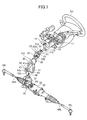
Fig. 1 is an entire configuration view generally showing the first embodiment that the shaft connection structure according to the invention is applied to a steering device for a vehicle. -
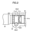
Fig. 2 is an enlarged side view showing the coupling part wherein the coupling member and the pinion shaft shown inFig. 1 are coupled with each other in the partially-broken manner. -
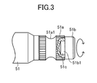
Fig. 3 is a side view showing the pinion shaft shown inFig. 2 in the partially-broken manner. -
Fig. 4 is a view explaining an operation in the first embodiment in the condition that the tightened shaft portion of the pinion shaft is not inserted into the shaft insertion hole of the coupling member (non-serration-fit condition) and the insertion restriction portion provided at the pinion shaft axially overlaps the bolt insertion aperture of the coupling member (when the mis-assembling is prevented). -
Fig. 5 is a view explaining an operation in the first embodiment in the condition that the tightened shaft portion of the pinion shaft is not inserted into the shaft insertion hole of the coupling member (non-serration-fit condition), the insertion restriction portion provided at the pinion shaft does not axially overlap the bolt insertion aperture of the coupling member, and the bolt is inserted into the bolt insertion aperture and is tightened thereto (when the mis-coupling occurs). -
Fig. 6 is a side view showing the second embodiment of the shaft connection structure according to the invention, corresponding toFig. 3 . -
Fig. 7 is a side view showing the third embodiment of the shaft connection structure according to the invention, corresponding toFig. 3 . -
Fig. 8 is a side view showing the fourth embodiment of the shaft connection structure according to the invention, corresponding toFig. 3 . - Below, each embodiment according to the invention will be explained by referring to the drawings.
Figs. 1-5 show the first embodiment that the shaft connection structure according to the invention is applied to a coupling part wherein alower joint yoke 42 of a loweruniversal joint 40 and apinion shaft 51 of asteering gear unit 50 of a steering device for a vehicle provided with a rack-assist electric power steering mechanism are coupled with each other. In this first embodiment, as shown inFig. 1 , a steering wheel SH which can be turned by a driver is coupled with thepinion shaft 51 of thesteering gear unit 50 via a transmission shaft CO such that a torque can be transmitted therebetween. - The transmission shaft CO transmits the steering wheel torque input by the driver to the
pinion shaft 51 of thesteering gear unit 50, and has a steeringmain shaft 10, an upperuniversal joint 20 for coupling the steeringmain shaft 10 and anintermediate shaft 30 with each other, and a loweruniversal joint 40 for coupling theintermediate shaft 30 and thepinion shaft 51 of thesteering gear unit 50. - The steering
main shaft 10 is rotatably supported in acolumn tube 13 assembled to a vehicle body (not shown) via a break-away bracket 11 and alower bracket 12. Further, the steeringmain shaft 10 integrally rotatably supports the steering wheel SH at its upper end portion. - The upper
universal joint 20 has anupper joint yoke 21, alower joint yoke 22 provided with a rubber coupling, and across spider 23. The upper andlower joint yokes yoke portions yoke portions cross spider 23 such that a torque can be transmitted therebetween. It should be noted that theupper joint yoke 21 is coupled with the steeringmain shaft 10 such that a torque can be transmitted therebetween by inserting the lower end portion of the steeringmain shaft 10 into an insertion hole (not shown) of a tightenedportion 21 b of the upper joint yoke and inserting abolt 24 into a bolt insertion aperture (not shown) of the tightenedportion 21 b of theupper joint yoke 21 and tightening thebolt 24. - The
intermediate shaft 30 is coupled with thelower joint yoke 22 such that a torque can be transmitted therebetween by inserting the upper end of theintermediate shaft 30 into an insertion hole (not shown) provided in a tightenedportion 22b of thelower joint yoke 22 of the upperuniversal joint 20 and inserting abolt 25 into a bolt insertion aperture (now shown) of the tightenedportion 22b of thelower joint yoke 22 and tightening thebolt 25. Further, anupper joint yoke 41 of the loweruniversal joint 40 is integrally secured to the lower end of theintermediate shaft 30. - The lower
universal joint 40 has anupper joint yoke 41, a lower joint yoke 42 (the coupling member of the invention), and across spider 43. The upper andlower joint yokes yoke portions yoke portions cross spider 43 such that a torque can be transmitted therebetween. - The
steering gear unit 50 has thepinion shaft 51 integrally rotatably coupled with thelower joint yoke 42 of the loweruniversal joint 40, a rack bar (not shown) which can stroke in the right and left direction in the vehicle along with the rotation of thepinion shaft 51, arack housing 52 for rotatably supporting thepinion shaft 51 and supporting the rack bar so as to be able to stroke, and a knownEPS actuator 53 housed in therack housing 52 for applying an assist torque (assist force) to the rack bar. Thepinion shaft 51 projects from therack housing 52 by a predetermined amount, and is coupled with thelower joint yoke 42 of the loweruniversal joint 40 at the projecting end portion thereof such that a required torque can be transmitted therebetween. It should be noted that the required torque is a torque required for the steering in this device. - The rack bar (not shown) is coupled with a pair of right and
left tie rods tie rods ball joints pinion shaft 51 rotates, the rack bar strokes in the right and left direction in the vehicle and the right and left front wheels are steered. - The
EPS actuator 53 is coaxially provided relative to the rack bar, and has an electric motor (not shown) assembled in therack housing 52 and a ball screw mechanism (not shown) to reduce the rotation of the electric motor and convert it to the stroke of the rack bar, and the rotation of the electric motor is controlled by an electric control unit (not shown) depending on the steering wheel torque detected by a torque sensor provided on the intermediate portion of thepinion shaft 51. - In the first embodiment, a tightened
shaft portion 51a having a predetermined length (serrations are formed on its outer periphery) is formed at the tip end portion (the right side end portion inFig. 2 ) of thepinion shaft 51, and an annular bolt engagement groove 51a1 is formed on the axially intermediate portion of the tightenedshaft portion 51a. Further, aninsertion restriction shaft 51 b is provided at the tip end of thepinion shaft 51. As shown inFigs. 2 and3 , theinsertion restriction shaft 51 b is constituted as a member independently of thepinion shaft 51, and has a diameter smaller than that of the tightenedshaft portion 51a. Further, as shown inFig. 3 , theinsertion restriction shaft 51 b at its mounting shaft portion 51b1 is coaxially assembled to amounting hole 51 c provided in the tip end of thepinion shaft 51 by press-fitting, and can be rotated relative to thepinion shaft 51 by a set torque smaller than the above-mentioned required torque. - On the other hand, as shown in
Figs. 1 and2 , thelower joint yoke 42 of the loweruniversal joint 40 has the above-mentionedyoke portion 42a and a tightenedportion 42b coupled with the tip end portion of thepinion shaft 51. The tightenedportion 42b has a radially extending slit 42b1 at its one end (the lower side inFig. 2 ), and has a shaft insertion hole 42b2 (serrations are formed on its inner periphery), into which the tightenedshaft portion 51a of thepinion shaft 51 can be inserted, and a bolt insertion aperture 42b3 provided to cross a part of the shaft insertion hole 42b2. - According to the above-explained constitution, in this first embodiment, the tightened
shaft portion 51a of thepinion shaft 51 and the tightenedportion 42b of thelower joint yoke 42 are coupled with each other such that the required torque can be transmitted therebetween by inserting the tightenedshaft portion 51a of thepinion shaft 51 into the shaft insertion hole 42b2 of thelower joint yoke 42, and inserting the bolt 44 (refer toFig. 1 ) into the bolt insertion aperture 42b3 of thelower joint yoke 42 and the bolt engagement groove 51a1 of thepinion shaft 51 and tightening thebolt 44 in the condition (the regular position condition shown inFig. 2 ) that the bolt engagement groove 51a1 of thepinion shaft 51 and the bolt insertion aperture 42b3 of thelower joint yoke 42 are axially aligned with each other. - Further, in this first embodiment, as shown in
Fig. 4 , when the tightenedshaft portion 51a of thepinion shaft 51 is inserted into the shaft insertion hole 42b2 of thelower joint yoke 42, in the condition (the non-regular position condition) that theinsertion restriction shaft 51 b axially overlaps the bolt insertion aperture 42b3 of thelower joint yoke 42, it is constituted that the insertion of thebolt 44 through the bolt insertion aperture 42b3 of thelower joint yoke 42 is restricted. - In the shaft connection structure of the first embodiment constituted as explained above, the
insertion restriction shaft 51 b having a diameter smaller than that of the tightenedshaft portion 51 a is provided at the tip end of the tightenedshaft portion 51 a of thepinion shaft 51 for restricting the insertion of thebolt 44 through the bolt insertion aperture 42b3 of thelower joint yoke 42 in the condition (the non-regular position condition shown inFig. 4 ) that theinsertion restriction shaft 51 b axially overlaps the bolt insertion aperture 42b3 of thelower joint yoke 42 when the tightenedshaft portion 51a of thepinion shaft 51 is inserted into the shaft insertion hole 42b2 of thelower joint yoke 42. Accordingly, in the above-mentioned non-regular position condition, thebolt 44 cannot be inserted throuth the bolt insertion aperture 42b3, and therefore the mis-assembling of the bolt 44 (the mis-assembling that thebolt 44 is inserted through the bolt insertion aperture 42b3 and is tightened) can be prevented, and the coupling of thepinion shaft 51 and thelower joint yoke 42 with each other can be prevented. - Further, in the shaft connection structure of this first embodiment, as shown in
Fig. 5 in the case that thebolt 44 is inserted into the bolt insertion aperture 42b3 of thelower joint yoke 42 and is tightened by a torque larger than or equal to the specified torque in the condition that theinsertion restriction shaft 51 b provided at the tip end of thepinion shaft 51 does not axially overlap the bolt insertion aperture 42b3 of thelower joint yoke 42 even when theinsertion restriction shaft 51 b is inserted into the shaft insertion hole 42b2 of thelower joint yoke 42, the outer periphery of theinsertion restriction shaft 51 b provided at thepinion shaft 51 and the inner periphery of the shaft insertion hole 42b2 (serrations are formed on its inner periphery) formed in thelower joint yoke 42 are frictionally engaged with each other, and therefore theinsertion restriction shaft 51 b provided at thepinion shaft 51 and thelower joint yoke 42 may be coupled with each other (mis-coupling) such that the required torque can be transmitted therebetween. - However, in this first embodiment, the
insertion restriction shaft 51 b can be rotated relative to thepinion shaft 51 by the set torque smaller than the required torque, and therefore when the above-mentioned mis-coupling occurs, even when theinsertion restriction shaft 51 b provided at thepinion shaft 51 and thelower joint yoke 42 are coupled with each other such that the required torque can be transmitted therebetween, theinsertion restriction shaft 51 b can be rotated relative to thepinion shaft 51 by the set torque smaller than the required torque. Accordingly, the above-mentioned mis-coupling can be detected on the basis of the relative rotation (for example, the offset of the steering neutral position in the steering device) between thepinion shaft 51 and the lowerjoint yoke 42 along with the rotation of theinsertion restriction shaft 51 b relative to thepinion shaft 51. - Further, in this first embodiment, the
insertion restriction shaft 51 b is constituted as a member independently of thepinion shaft 51, and is coaxially assembled to thepinion shaft 51 by press-fitting, and therefore the above-mentioned set torque can be adjusted by the press-fitting amount (the difference in the diameter between the mountinghole 51c provided in thepinion shaft 51 and the mounting shaft portion 51b1 of theinsertion restriction shaft 51 b), and the first embodiment can be simply inexpensively embodied. - It should be noted that this first embodiment is one which the present invention applies to the coupling part (a part which an assist torque is not applied to) wherein the lower
joint yoke 42 of the loweruniversal joint 40 and thepinion shaft 51 of thesteering gear unit 50 of the steering device for the vehicle provided with a rack-assist electric power steering mechanism. An assist torque is applied to the similar coupling part in the steering device for the vehicle provided with the column-assist electric power steering, and therefore in the case that the prior art applies to the coupling part, the above-mentioned mis-coupling can be easily detected. - Accordingly, the enhancement of the detection of the mis-coupling in the case that the present invention in place of the prior art applies to the above-mentioned coupling part in the steering device for the vehicle provided with the rack-assist electric power steering mechanism can be increased, compared with the enhancement of the detection of the mis-coupling in the case that the present invention in place of the prior art applies to the similar coupling part (the part which the assist torque is applied to) in the steering device for the vehicle provided with the column-assist electric power steering mechanism. Accordingly, the present invention is preferable for the coupling part (the part which the assist torque is not applied to) in the steering device for the vehicle provided with the rack-assist electric power steering mechanism.
- In the above-explained first embodiment, the present invention is embodied by employing the constitution shown in
Fig. 3 , however, the present invention can be embodied, for example, by employing the constitution of the second embodiment shown inFig. 6 , or the third embodiment shown inFig. 7 , or the fourth embodiment shown inFig. 8 . - In the second embodiment shown in
Fig. 6 , in place of theinsertion restriction shaft 51 b of the above-explained first embodiment, aninsertion restriction portion 151 b is employed. Theinsertion restriction portion 151 b is integrally formed on apinion shaft 151, is coaxially connected with the tip end of a tightenedshaft portion 151a of thepinion shaft 151 via a low-strength shaft portion (small-diameter shaft portion) 151c, and can be rotated relative to thepinion shaft 151 by a set torque smaller than the above-mentioned required torque. The tightenedshaft portion 151a is substantially the same as the tightenedshaft portion 51 a of the above-explained first embodiment, and is formed with a bolt engagement groove 151a1 on its axially intermediate portion as in the above-explained first embodiment. - In this second embodiment, as in the above-explained first embodiment, the above-mentioned mis-assembling can be prevented, and the above-mentioned mis-coupling can be detected. Further, the
insertion restriction portion 151b is integrally formed on thepinion shaft 151, and is coaxially connected with the tip end of the tightenedshaft portion 151 a via the low-strength shaft portion 151c, and therefore the increase of the number of the parts and the steps of the assembling does not occur, and the second embodiment can be inexpensively embodied. - In the third embodiment shown in
Fig. 7 , aninsertion restriction shaft 251 b is employed in place of theinsertion restriction shaft 51 b of the above-explained first embodiment. Theinsertion restriction shaft 251 b is formed to have a cylindrical shape as a member independently of apinion shaft 251, is coaxially assembled to a tightenedshaft portion 251a of thepinion shaft 251 by using a steppedbolt 251c having a hexagonal aperture at the center portion of its head, and can be rotated relative to thepinion shaft 251 by a set torque smaller than the above-mentioned required torque. The tightenedshaft portion 251a is substantially the same as the tightenedshaft portion 51a of the above-explained first embodiment, and is formed with a bolt engagement groove 251a1 on its axially intermediate portion as in the above-explained first embodiment. In this third embodiment, as in the above-explained first embodiment, the above-mentioned mis-assembling can be prevented and the above-mentioned mis-coupling can be detected. - In the fourth embodiment shown in
Fig. 8 , aninsertion restriction shaft 351 b is employed in place of theinsertion restriction shaft 51 b of the above-explained first embodiment. Theinsertion restriction shaft 351b is formed to have a cylindrical shape as a member independently of apinion shaft 351, and is rotatably fit onto asupport shaft portion 351 c coaxially formed on a tightenedshaft portion 351 a of thepinion shaft 351. Fall-out of theinsertion restriction shaft 351 b is prevented by aflange portion 351 c1 formed by swaging the tip end of thesupport shaft portion 351 c, and can be rotated relative to thepinion shaft 351 by a set torque smaller than the above-mentioned required torque. The tightenedshaft portion 351a is substantially the same as the tightenedshaft portion 51 a of the above-explained first embodiment, and is formed with a bolt engagement groove 351a1 on its axially intermediate portion as in the above-explained first embodiment. In this fourth embodiment, as in the first embodiment, the above-mentioned mis-assembling can be prevented, and the above-mentioned mis-coupling can be detected. - In each of the above-explained embodiments, in the steering device for the vehicle, the shaft connection structure according to the present invention is applied to the coupling part wherein the lower
joint yoke 42 of the loweruniversal joint 40 and thepinion shaft 51 are coupled with each other, however, the shaft connection structure according to the present invention can be applied to the other similar coupling part in the steering device for the vehicle. - Further, in each of the above-explained embodiments, the shaft connection structure according to the present invention is applied to the coupling part on the steering wheel side (the input side) of the rack bar of the steering device for the vehicle provided with the rack-assist electric power steering mechanism, however, the shaft connection structure according to the present invention can be applied to any coupling parts in the other steering device for the vehicle, for example, the coupling part on the steering wheel side (the input side) of the rack bar in the steering device for the vehicle provided with the rack-assist hydraulic power steering mechanism, or the coupling part on the steering wheel side (the input side) of the pinion shaft in the steering device for the vehicle provided with the pinion-assist electric power steering mechanism, or the coupling part on the wheel side (the output side) of the steering shaft in the steering device for the vehicle provided with the column-assist electric power steering mechanism.
- Further, the shaft connection structure according to the present invention can be applied to the similar coupling parts in the various devices other than the steering device for the vehicle as in the above-explained embodiments or along with suitable modification.
Claims (5)
- A shaft connection structure, comprising:a shaft having a tightened shaft portion at its tip end portion and an annular bolt engagement groove on the axially intermediate portion of the tightened shaft portion;a coupling member having a tightened portion formed with a shaft insertion hole, into which the tightened shaft portion of the shaft can be inserted, and a bolt insertion aperture provided to cross a part of the shaft insertion hole at the tightened portion; anda bolt which is inserted into the bolt insertion aperture of the coupling member and is tightened;wherein the tightened shaft portion of the shaft and the tightened portion of the coupling member are coupled with each other such that a required torque can be transmitted therebetween by inserting the tightened shaft portion of the shaft into the shaft insertion hole of the coupling member, and inserting the bolt into the bolt insertion aperture of the coupling member and the bolt engagement groove of the shaft and tightening the bolt in the condition that the bolt engagement groove of the shaft and the bolt insertion aperture of the coupling member are axially aligned with each other;characterized in that an insertion restriction portion having a diameter smaller than that of the tightened shaft portion is provided at the tip end of the tightened shaft portion of the shaft for restricting the insertion of the bolt through the bolt insertion aperture of the coupling member in the condition that the insertion restriction portion axially overlaps the bolt insertion aperture of the coupling member when the tightened shaft portion of the shaft is inserted into the shaft insertion hole of the coupling member; andthe insertion restriction portion can be rotated relative to the shaft by a set torque smaller than the required torque.
- The shaft connection structure as set forth in claim 1, characterized in that the insertion restriction portion is constituted as a member independently of the shaft, and is coaxially assembled to the shaft by press-fitting.
- The shaft connection structure as set forth in claim 1, characterized in that the insertion restriction portion is integrally formed on the shaft, and is coaxially connected with the tip end of the tightened shaft portion via a low-strength shaft portion.
- The shaft connection structure as set forth in claim 1, characterized in that the insertion restriction portion is formed to have a cylindrical shape as a member independently of the shaft, and is coaxially assembled to the shaft by a stepped bolt.
- The shaft connection structure as set forth in claim 1, characterized in that the insertion restriction portion is formed to have a cylindrical shape as a member independently of the shaft, is rotatably fit onto a support shaft portion coaxially formed in the shaft, and is prevented from being fallen out therefrom by swaging the tip end of the support shaft portion.
Applications Claiming Priority (1)
| Application Number | Priority Date | Filing Date | Title |
|---|---|---|---|
| PCT/JP2009/057423 WO2010116537A1 (en) | 2009-04-07 | 2009-04-07 | Shaft coupling structure |
Publications (3)
| Publication Number | Publication Date |
|---|---|
| EP2418141A1 true EP2418141A1 (en) | 2012-02-15 |
| EP2418141A4 EP2418141A4 (en) | 2014-10-22 |
| EP2418141B1 EP2418141B1 (en) | 2017-10-18 |
Family
ID=42935844
Family Applications (1)
| Application Number | Title | Priority Date | Filing Date |
|---|---|---|---|
| EP09843045.7A Not-in-force EP2418141B1 (en) | 2009-04-07 | 2009-04-07 | Shaft coupling structure |
Country Status (5)
| Country | Link |
|---|---|
| US (1) | US8277142B2 (en) |
| EP (1) | EP2418141B1 (en) |
| JP (1) | JP4992982B2 (en) |
| CN (1) | CN101939206B (en) |
| WO (1) | WO2010116537A1 (en) |
Families Citing this family (16)
| Publication number | Priority date | Publication date | Assignee | Title |
|---|---|---|---|---|
| KR101411180B1 (en) | 2011-03-07 | 2014-06-23 | 주식회사 만도 | Steering shaft with miss-assembly prevention structure |
| CN102849617B (en) * | 2011-06-30 | 2015-11-04 | 沈阳铝镁设计研究院有限公司 | The horizontal wheel device of adjustable interval |
| KR101755447B1 (en) * | 2011-07-28 | 2017-07-07 | 현대자동차 주식회사 | Connecting structure of universal joint |
| KR101631509B1 (en) * | 2011-09-29 | 2016-06-27 | 남양공업주식회사 | Apparatus for preventing misassembling of a universal joint |
| KR101405591B1 (en) * | 2011-10-24 | 2014-06-10 | 주식회사 만도 | Steering shaft with miss-assembly prevention structure |
| KR101421334B1 (en) * | 2012-03-02 | 2014-07-18 | 주식회사 만도 | Intermediate Shaft of Steering Apparatus for Vehicle |
| JP2014015130A (en) * | 2012-07-09 | 2014-01-30 | Jtekt Corp | Steering device |
| US20140119822A1 (en) * | 2012-10-30 | 2014-05-01 | Sir Meccanica S.P.A. | Modular shaft for machine tools |
| FR3006400B1 (en) * | 2013-05-29 | 2015-06-19 | Zf Systemes De Direction Nacam Sas | SECURE ASSEMBLY OF TWO PIECES BY VISSAGE |
| CN105378315B (en) | 2013-07-16 | 2017-12-08 | 日本精工株式会社 | Transfer |
| US9581205B2 (en) * | 2013-08-05 | 2017-02-28 | GM Global Technology Operations LLC | Coupling element with non-regular shaft interface |
| CN103387002A (en) * | 2013-08-16 | 2013-11-13 | 安徽江淮汽车股份有限公司 | Structure for preventing misconnection of intermediate shaft and input shaft of diverter |
| JP6019080B2 (en) * | 2014-09-26 | 2016-11-02 | 富士重工業株式会社 | Connecting structure for vehicle underbody members |
| CN105501286A (en) * | 2015-12-23 | 2016-04-20 | 浙江吉利汽车研究院有限公司 | Guiding element, steering gear assembly and steering system |
| US9821843B1 (en) * | 2017-01-06 | 2017-11-21 | Robert Bosch Automotive Steering Llc | Tie rod |
| JP2022143667A (en) * | 2021-03-18 | 2022-10-03 | 本田技研工業株式会社 | Vehicle steering device and its assembly method |
Family Cites Families (38)
| Publication number | Priority date | Publication date | Assignee | Title |
|---|---|---|---|---|
| US2448278A (en) * | 1944-09-21 | 1948-08-31 | Minneapolis Moline Power Co | Power transmission coupling |
| US2780830A (en) * | 1955-06-20 | 1957-02-12 | Jr Archer W Kammerer | Pin retainer |
| DE1220675B (en) * | 1959-08-19 | 1966-07-07 | Bernhard Walterscheid Mueller | Securing a hub on a splined shaft |
| SE321900B (en) * | 1967-12-08 | 1970-03-16 | Atlas Copco Ab | |
| US3796464A (en) * | 1972-09-27 | 1974-03-12 | Carmet Co | Resilient connection for mining pick and bushing |
| US4372703A (en) * | 1981-01-12 | 1983-02-08 | The Singer Company | Tapered screw fastening means for bushings, sleeves and bearings |
| FR2547372B1 (en) * | 1983-06-13 | 1985-08-30 | Nacam | DEVICE FOR DETECTING THE POSITION OF A SHAFT IN A COUPLING ELEMENT, IN PARTICULAR A CARDAN JOINT JAW |
| JPS60102524U (en) * | 1983-12-19 | 1985-07-12 | 日産自動車株式会社 | steering device |
| EP0225554B1 (en) * | 1985-11-27 | 1990-05-09 | Matsui Walterscheid Ltd. | Removable coupling device |
| IT1210743B (en) * | 1987-05-19 | 1989-09-20 | Fiat Auto Spa | DEVICE FOR THE CORRECT POSITIONING OF THE LOWER SHAFT STEERING CONTROL TO THE PINION OF THE STEERING BOX AND TO THE UPPER SHAFT |
| IT214267Z2 (en) * | 1988-02-18 | 1990-04-24 | Fiat Auto Spa | SAFETY RING FOR CORRECT CONNECTION OF THE LOWER SHAFT STEERING CONTROL TO THE PINION GUIDE BOX |
| EP0430572A3 (en) * | 1989-11-25 | 1991-11-21 | Hahn & Kolb Gmbh & Co. | Coupling |
| JPH0454325A (en) | 1990-06-22 | 1992-02-21 | Aisin Seiki Co Ltd | Brake for vehicle |
| JPH0454325U (en) | 1990-07-31 | 1992-05-11 | ||
| JPH04113334A (en) | 1990-09-03 | 1992-04-14 | Matsushita Electric Ind Co Ltd | Production of nonlinear optical material |
| JP2526189Y2 (en) * | 1991-03-20 | 1997-02-19 | 日本精工株式会社 | Coupling device for yoke and rotating shaft of universal joint |
| DE4129042C2 (en) * | 1991-08-31 | 1995-06-14 | Bayerische Motoren Werke Ag | Safety device for precise connection of a clamping sleeve to a gear shaft |
| JPH06329037A (en) * | 1993-05-25 | 1994-11-29 | T R W S S J Kk | Steering system input shaft and torsion bar fixing method and torsion bar suited for this method |
| JPH07186977A (en) * | 1993-12-28 | 1995-07-25 | Nissan Motor Co Ltd | Assembling structure |
| DE4419078A1 (en) * | 1994-05-31 | 1995-12-07 | Trw Repa Gmbh | Fastening device for a vehicle steering wheel |
| ES2114405B1 (en) * | 1994-08-11 | 1999-02-16 | Daumal Castellon Melchor | FAST FIXATION SYSTEM. |
| US5628578A (en) * | 1995-07-28 | 1997-05-13 | Dana Corporation | Alternate pinch bolt yoke construction |
| JPH09123919A (en) * | 1995-08-31 | 1997-05-13 | Toyoda Gosei Co Ltd | Mounting structure for steering wheel |
| DE29516622U1 (en) * | 1995-10-20 | 1996-01-25 | Trw Occupant Restraint Systems Gmbh, 73551 Alfdorf | Fastening a vehicle steering wheel to a steering shaft |
| JPH09109903A (en) * | 1995-10-24 | 1997-04-28 | Daihatsu Motor Co Ltd | Steering mechanism |
| AU683813B2 (en) * | 1996-02-26 | 1997-11-20 | Toyoda Gosei Co. Ltd. | Steering wheel, mounting structure thereof and boss structure thereof |
| JP3932597B2 (en) * | 1997-03-28 | 2007-06-20 | マツダ株式会社 | Shaft coupling structure |
| JP3698289B2 (en) * | 1997-10-15 | 2005-09-21 | スズキ株式会社 | Car steering device |
| DE29808420U1 (en) * | 1998-05-05 | 1998-07-30 | Petri Ag, 63743 Aschaffenburg | Device for fastening a hub on a shaft, in particular a steering wheel hub on a steering column |
| FR2784738B1 (en) * | 1998-10-19 | 2000-12-08 | Air Liquide | BUILT-IN MANOMETER FOR PRESSURIZED FLUID DELIVERY DEVICE, IN PARTICULAR FOR GAS REGULATOR |
| JP4113334B2 (en) | 2001-01-30 | 2008-07-09 | 株式会社ホンダエレシス | Prior vehicle recognition method and apparatus |
| US6942415B2 (en) * | 2002-02-26 | 2005-09-13 | The Torrington Company | Shaft assembly safety mechanism |
| US6739790B1 (en) * | 2002-12-13 | 2004-05-25 | The Torrington Company | Shaft assembly safety mechanism |
| US7066679B2 (en) * | 2003-11-14 | 2006-06-27 | Timken Us Corporation | Shaft assembly safety mechanism |
| JP4441600B2 (en) * | 2005-02-17 | 2010-03-31 | 株式会社ジェイテクト | Misassembly prevention tool and universal joint including the same |
| US8015996B2 (en) * | 2005-04-28 | 2011-09-13 | United Technologies Corporation | Gas turbine engine air valve assembly |
| JP4735974B2 (en) * | 2006-03-30 | 2011-07-27 | 株式会社ジェイテクト | Joint structure of universal joint yoke and shaft |
| JP2008202742A (en) * | 2007-02-22 | 2008-09-04 | Nsk Ltd | Yoke-shaft connection structure and steering device using the same |
-
2009
- 2009-04-07 WO PCT/JP2009/057423 patent/WO2010116537A1/en not_active Ceased
- 2009-04-07 US US12/676,515 patent/US8277142B2/en not_active Expired - Fee Related
- 2009-04-07 JP JP2009550115A patent/JP4992982B2/en not_active Expired - Fee Related
- 2009-04-07 EP EP09843045.7A patent/EP2418141B1/en not_active Not-in-force
- 2009-04-07 CN CN2009801003502A patent/CN101939206B/en not_active Expired - Fee Related
Also Published As
| Publication number | Publication date |
|---|---|
| WO2010116537A1 (en) | 2010-10-14 |
| JPWO2010116537A1 (en) | 2012-10-18 |
| EP2418141B1 (en) | 2017-10-18 |
| EP2418141A4 (en) | 2014-10-22 |
| US8277142B2 (en) | 2012-10-02 |
| JP4992982B2 (en) | 2012-08-08 |
| US20110129294A1 (en) | 2011-06-02 |
| CN101939206B (en) | 2013-02-13 |
| CN101939206A (en) | 2011-01-05 |
Similar Documents
| Publication | Publication Date | Title |
|---|---|---|
| EP2418141B1 (en) | Shaft coupling structure | |
| US20120322566A1 (en) | Reducer of electric power steering system | |
| KR101452557B1 (en) | Electric Power Steering Apparatus | |
| US8500564B2 (en) | Shaft-and-yoke coupling structure and vehicle steering system | |
| US8454039B2 (en) | Vehicle steering system | |
| US20140147197A1 (en) | Coupling structure for coupling shaft to universal joint yoke, coupling method for coupling shaft to universal joint yoke, and intermediate shaft | |
| KR20170027176A (en) | Power Transmission Device of Electric Power Steering Apparatus | |
| KR102668785B1 (en) | Steering Column for Vehicle | |
| KR20190047883A (en) | Steer-By-Wire Type Steering Apparatus | |
| JP2001180506A (en) | Electric power steering device | |
| KR20170041983A (en) | Power Transmission Device of Electric Power Steering Apparatus | |
| JP5130915B2 (en) | Electric power steering device | |
| US20180086364A1 (en) | Steering column for vehicle | |
| EP3081458B1 (en) | Electric power steering device and method for assembling same | |
| KR102350046B1 (en) | Steering column for vehicle | |
| KR20090021719A (en) | Damping Coupler and Reducer Equipped with It | |
| KR102327340B1 (en) | Steering Column for Vehicle | |
| KR102843452B1 (en) | Steer-by-wire type steering apparatus | |
| KR20120075780A (en) | Electrical power steering apparatus | |
| JP2008132845A (en) | Joint yoke and shaft coupling structure in a steering device | |
| JP5332723B2 (en) | Intermediate shaft | |
| EP2921373A1 (en) | Steering device | |
| KR20120139968A (en) | Torque sensor system and electric power steering apparatus having the same | |
| JP2002340017A (en) | Joint mechanism, and steering operation assisting device using the same | |
| KR101405547B1 (en) | Rack and Pinion Type Steering Apparatus |
Legal Events
| Date | Code | Title | Description |
|---|---|---|---|
| PUAI | Public reference made under article 153(3) epc to a published international application that has entered the european phase |
Free format text: ORIGINAL CODE: 0009012 |
|
| 17P | Request for examination filed |
Effective date: 20110926 |
|
| AK | Designated contracting states |
Kind code of ref document: A1 Designated state(s): AT BE BG CH CY CZ DE DK EE ES FI FR GB GR HR HU IE IS IT LI LT LU LV MC MK MT NL NO PL PT RO SE SI SK TR |
|
| DAX | Request for extension of the european patent (deleted) | ||
| RAP1 | Party data changed (applicant data changed or rights of an application transferred) |
Owner name: TOYOTA JIDOSHA KABUSHIKI KAISHA |
|
| A4 | Supplementary search report drawn up and despatched |
Effective date: 20140918 |
|
| RIC1 | Information provided on ipc code assigned before grant |
Ipc: B62D 1/16 20060101ALI20140912BHEP Ipc: F16D 1/08 20060101ALI20140912BHEP Ipc: B62D 1/20 20060101AFI20140912BHEP Ipc: F16D 3/38 20060101ALI20140912BHEP |
|
| 17Q | First examination report despatched |
Effective date: 20160817 |
|
| STAA | Information on the status of an ep patent application or granted ep patent |
Free format text: STATUS: EXAMINATION IS IN PROGRESS |
|
| GRAP | Despatch of communication of intention to grant a patent |
Free format text: ORIGINAL CODE: EPIDOSNIGR1 |
|
| STAA | Information on the status of an ep patent application or granted ep patent |
Free format text: STATUS: GRANT OF PATENT IS INTENDED |
|
| INTG | Intention to grant announced |
Effective date: 20170418 |
|
| GRAS | Grant fee paid |
Free format text: ORIGINAL CODE: EPIDOSNIGR3 |
|
| GRAA | (expected) grant |
Free format text: ORIGINAL CODE: 0009210 |
|
| STAA | Information on the status of an ep patent application or granted ep patent |
Free format text: STATUS: THE PATENT HAS BEEN GRANTED |
|
| RIN1 | Information on inventor provided before grant (corrected) |
Inventor name: TANAKA, SEIJI Inventor name: HOSHINO, SHIGERU |
|
| RAP1 | Party data changed (applicant data changed or rights of an application transferred) |
Owner name: TOYOTA JIDOSHA KABUSHIKI KAISHA |
|
| AK | Designated contracting states |
Kind code of ref document: B1 Designated state(s): AT BE BG CH CY CZ DE DK EE ES FI FR GB GR HR HU IE IS IT LI LT LU LV MC MK MT NL NO PL PT RO SE SI SK TR |
|
| REG | Reference to a national code |
Ref country code: GB Ref legal event code: FG4D |
|
| REG | Reference to a national code |
Ref country code: CH Ref legal event code: EP |
|
| REG | Reference to a national code |
Ref country code: AT Ref legal event code: REF Ref document number: 937668 Country of ref document: AT Kind code of ref document: T Effective date: 20171115 Ref country code: IE Ref legal event code: FG4D |
|
| REG | Reference to a national code |
Ref country code: DE Ref legal event code: R096 Ref document number: 602009048960 Country of ref document: DE |
|
| REG | Reference to a national code |
Ref country code: DE Ref legal event code: R084 Ref document number: 602009048960 Country of ref document: DE |
|
| REG | Reference to a national code |
Ref country code: GB Ref legal event code: 746 Effective date: 20180125 Ref country code: NL Ref legal event code: MP Effective date: 20171018 |
|
| REG | Reference to a national code |
Ref country code: LT Ref legal event code: MG4D |
|
| REG | Reference to a national code |
Ref country code: AT Ref legal event code: MK05 Ref document number: 937668 Country of ref document: AT Kind code of ref document: T Effective date: 20171018 Ref country code: FR Ref legal event code: PLFP Year of fee payment: 10 |
|
| PG25 | Lapsed in a contracting state [announced via postgrant information from national office to epo] |
Ref country code: NL Free format text: LAPSE BECAUSE OF FAILURE TO SUBMIT A TRANSLATION OF THE DESCRIPTION OR TO PAY THE FEE WITHIN THE PRESCRIBED TIME-LIMIT Effective date: 20171018 |
|
| PG25 | Lapsed in a contracting state [announced via postgrant information from national office to epo] |
Ref country code: NO Free format text: LAPSE BECAUSE OF FAILURE TO SUBMIT A TRANSLATION OF THE DESCRIPTION OR TO PAY THE FEE WITHIN THE PRESCRIBED TIME-LIMIT Effective date: 20180118 Ref country code: SE Free format text: LAPSE BECAUSE OF FAILURE TO SUBMIT A TRANSLATION OF THE DESCRIPTION OR TO PAY THE FEE WITHIN THE PRESCRIBED TIME-LIMIT Effective date: 20171018 Ref country code: FI Free format text: LAPSE BECAUSE OF FAILURE TO SUBMIT A TRANSLATION OF THE DESCRIPTION OR TO PAY THE FEE WITHIN THE PRESCRIBED TIME-LIMIT Effective date: 20171018 Ref country code: LT Free format text: LAPSE BECAUSE OF FAILURE TO SUBMIT A TRANSLATION OF THE DESCRIPTION OR TO PAY THE FEE WITHIN THE PRESCRIBED TIME-LIMIT Effective date: 20171018 Ref country code: ES Free format text: LAPSE BECAUSE OF FAILURE TO SUBMIT A TRANSLATION OF THE DESCRIPTION OR TO PAY THE FEE WITHIN THE PRESCRIBED TIME-LIMIT Effective date: 20171018 |
|
| PG25 | Lapsed in a contracting state [announced via postgrant information from national office to epo] |
Ref country code: IS Free format text: LAPSE BECAUSE OF FAILURE TO SUBMIT A TRANSLATION OF THE DESCRIPTION OR TO PAY THE FEE WITHIN THE PRESCRIBED TIME-LIMIT Effective date: 20180218 Ref country code: BG Free format text: LAPSE BECAUSE OF FAILURE TO SUBMIT A TRANSLATION OF THE DESCRIPTION OR TO PAY THE FEE WITHIN THE PRESCRIBED TIME-LIMIT Effective date: 20180118 Ref country code: LV Free format text: LAPSE BECAUSE OF FAILURE TO SUBMIT A TRANSLATION OF THE DESCRIPTION OR TO PAY THE FEE WITHIN THE PRESCRIBED TIME-LIMIT Effective date: 20171018 Ref country code: HR Free format text: LAPSE BECAUSE OF FAILURE TO SUBMIT A TRANSLATION OF THE DESCRIPTION OR TO PAY THE FEE WITHIN THE PRESCRIBED TIME-LIMIT Effective date: 20171018 Ref country code: AT Free format text: LAPSE BECAUSE OF FAILURE TO SUBMIT A TRANSLATION OF THE DESCRIPTION OR TO PAY THE FEE WITHIN THE PRESCRIBED TIME-LIMIT Effective date: 20171018 Ref country code: GR Free format text: LAPSE BECAUSE OF FAILURE TO SUBMIT A TRANSLATION OF THE DESCRIPTION OR TO PAY THE FEE WITHIN THE PRESCRIBED TIME-LIMIT Effective date: 20180119 |
|
| REG | Reference to a national code |
Ref country code: DE Ref legal event code: R097 Ref document number: 602009048960 Country of ref document: DE |
|
| PG25 | Lapsed in a contracting state [announced via postgrant information from national office to epo] |
Ref country code: CZ Free format text: LAPSE BECAUSE OF FAILURE TO SUBMIT A TRANSLATION OF THE DESCRIPTION OR TO PAY THE FEE WITHIN THE PRESCRIBED TIME-LIMIT Effective date: 20171018 Ref country code: SK Free format text: LAPSE BECAUSE OF FAILURE TO SUBMIT A TRANSLATION OF THE DESCRIPTION OR TO PAY THE FEE WITHIN THE PRESCRIBED TIME-LIMIT Effective date: 20171018 Ref country code: EE Free format text: LAPSE BECAUSE OF FAILURE TO SUBMIT A TRANSLATION OF THE DESCRIPTION OR TO PAY THE FEE WITHIN THE PRESCRIBED TIME-LIMIT Effective date: 20171018 Ref country code: DK Free format text: LAPSE BECAUSE OF FAILURE TO SUBMIT A TRANSLATION OF THE DESCRIPTION OR TO PAY THE FEE WITHIN THE PRESCRIBED TIME-LIMIT Effective date: 20171018 |
|
| PLBE | No opposition filed within time limit |
Free format text: ORIGINAL CODE: 0009261 |
|
| STAA | Information on the status of an ep patent application or granted ep patent |
Free format text: STATUS: NO OPPOSITION FILED WITHIN TIME LIMIT |
|
| PG25 | Lapsed in a contracting state [announced via postgrant information from national office to epo] |
Ref country code: RO Free format text: LAPSE BECAUSE OF FAILURE TO SUBMIT A TRANSLATION OF THE DESCRIPTION OR TO PAY THE FEE WITHIN THE PRESCRIBED TIME-LIMIT Effective date: 20171018 Ref country code: IT Free format text: LAPSE BECAUSE OF FAILURE TO SUBMIT A TRANSLATION OF THE DESCRIPTION OR TO PAY THE FEE WITHIN THE PRESCRIBED TIME-LIMIT Effective date: 20171018 Ref country code: PL Free format text: LAPSE BECAUSE OF FAILURE TO SUBMIT A TRANSLATION OF THE DESCRIPTION OR TO PAY THE FEE WITHIN THE PRESCRIBED TIME-LIMIT Effective date: 20171018 |
|
| 26N | No opposition filed |
Effective date: 20180719 |
|
| PG25 | Lapsed in a contracting state [announced via postgrant information from national office to epo] |
Ref country code: MC Free format text: LAPSE BECAUSE OF FAILURE TO SUBMIT A TRANSLATION OF THE DESCRIPTION OR TO PAY THE FEE WITHIN THE PRESCRIBED TIME-LIMIT Effective date: 20171018 Ref country code: SI Free format text: LAPSE BECAUSE OF FAILURE TO SUBMIT A TRANSLATION OF THE DESCRIPTION OR TO PAY THE FEE WITHIN THE PRESCRIBED TIME-LIMIT Effective date: 20171018 |
|
| REG | Reference to a national code |
Ref country code: CH Ref legal event code: PL |
|
| REG | Reference to a national code |
Ref country code: BE Ref legal event code: MM Effective date: 20180430 |
|
| REG | Reference to a national code |
Ref country code: IE Ref legal event code: MM4A |
|
| PG25 | Lapsed in a contracting state [announced via postgrant information from national office to epo] |
Ref country code: LU Free format text: LAPSE BECAUSE OF NON-PAYMENT OF DUE FEES Effective date: 20180407 |
|
| PG25 | Lapsed in a contracting state [announced via postgrant information from national office to epo] |
Ref country code: CH Free format text: LAPSE BECAUSE OF NON-PAYMENT OF DUE FEES Effective date: 20180430 Ref country code: BE Free format text: LAPSE BECAUSE OF NON-PAYMENT OF DUE FEES Effective date: 20180430 Ref country code: LI Free format text: LAPSE BECAUSE OF NON-PAYMENT OF DUE FEES Effective date: 20180430 |
|
| PG25 | Lapsed in a contracting state [announced via postgrant information from national office to epo] |
Ref country code: IE Free format text: LAPSE BECAUSE OF NON-PAYMENT OF DUE FEES Effective date: 20180407 |
|
| PG25 | Lapsed in a contracting state [announced via postgrant information from national office to epo] |
Ref country code: MT Free format text: LAPSE BECAUSE OF NON-PAYMENT OF DUE FEES Effective date: 20180407 |
|
| PG25 | Lapsed in a contracting state [announced via postgrant information from national office to epo] |
Ref country code: TR Free format text: LAPSE BECAUSE OF FAILURE TO SUBMIT A TRANSLATION OF THE DESCRIPTION OR TO PAY THE FEE WITHIN THE PRESCRIBED TIME-LIMIT Effective date: 20171018 |
|
| PG25 | Lapsed in a contracting state [announced via postgrant information from national office to epo] |
Ref country code: PT Free format text: LAPSE BECAUSE OF FAILURE TO SUBMIT A TRANSLATION OF THE DESCRIPTION OR TO PAY THE FEE WITHIN THE PRESCRIBED TIME-LIMIT Effective date: 20171018 Ref country code: HU Free format text: LAPSE BECAUSE OF FAILURE TO SUBMIT A TRANSLATION OF THE DESCRIPTION OR TO PAY THE FEE WITHIN THE PRESCRIBED TIME-LIMIT; INVALID AB INITIO Effective date: 20090407 |
|
| PG25 | Lapsed in a contracting state [announced via postgrant information from national office to epo] |
Ref country code: MK Free format text: LAPSE BECAUSE OF NON-PAYMENT OF DUE FEES Effective date: 20171018 Ref country code: CY Free format text: LAPSE BECAUSE OF FAILURE TO SUBMIT A TRANSLATION OF THE DESCRIPTION OR TO PAY THE FEE WITHIN THE PRESCRIBED TIME-LIMIT Effective date: 20171018 |
|
| PGFP | Annual fee paid to national office [announced via postgrant information from national office to epo] |
Ref country code: FR Payment date: 20210310 Year of fee payment: 13 |
|
| PGFP | Annual fee paid to national office [announced via postgrant information from national office to epo] |
Ref country code: GB Payment date: 20210318 Year of fee payment: 13 |
|
| PGFP | Annual fee paid to national office [announced via postgrant information from national office to epo] |
Ref country code: DE Payment date: 20210316 Year of fee payment: 13 |
|
| REG | Reference to a national code |
Ref country code: DE Ref legal event code: R119 Ref document number: 602009048960 Country of ref document: DE |
|
| GBPC | Gb: european patent ceased through non-payment of renewal fee |
Effective date: 20220407 |
|
| PG25 | Lapsed in a contracting state [announced via postgrant information from national office to epo] |
Ref country code: GB Free format text: LAPSE BECAUSE OF NON-PAYMENT OF DUE FEES Effective date: 20220407 Ref country code: FR Free format text: LAPSE BECAUSE OF NON-PAYMENT OF DUE FEES Effective date: 20220430 Ref country code: DE Free format text: LAPSE BECAUSE OF NON-PAYMENT OF DUE FEES Effective date: 20221103 |