EP2417433B1 - Verfahren und vorrichtung zur erkennung von anomalien in reifenmetalldrähten - Google Patents
Verfahren und vorrichtung zur erkennung von anomalien in reifenmetalldrähten Download PDFInfo
- Publication number
- EP2417433B1 EP2417433B1 EP10762216.9A EP10762216A EP2417433B1 EP 2417433 B1 EP2417433 B1 EP 2417433B1 EP 10762216 A EP10762216 A EP 10762216A EP 2417433 B1 EP2417433 B1 EP 2417433B1
- Authority
- EP
- European Patent Office
- Prior art keywords
- magnetic field
- sensors
- field sensors
- signals
- signal
- Prior art date
- Legal status (The legal status is an assumption and is not a legal conclusion. Google has not performed a legal analysis and makes no representation as to the accuracy of the status listed.)
- Active
Links
Images


Classifications
-
- G—PHYSICS
- G01—MEASURING; TESTING
- G01N—INVESTIGATING OR ANALYSING MATERIALS BY DETERMINING THEIR CHEMICAL OR PHYSICAL PROPERTIES
- G01N27/00—Investigating or analysing materials by the use of electric, electrochemical, or magnetic means
- G01N27/72—Investigating or analysing materials by the use of electric, electrochemical, or magnetic means by investigating magnetic variables
- G01N27/82—Investigating or analysing materials by the use of electric, electrochemical, or magnetic means by investigating magnetic variables for investigating the presence of flaws
Definitions
- the present subject matter relates to tire testing.
- the present subject matter relates to methods and apparatus for non destructive testing for the presence of anomalies in metallic cables within a tire.
- the present invention relates to an apparatus according to the premable of claim 1 and a method according to the preamble of claim 8, such as they are for example known from GB 2 071 331 A or US R E40 166 E1 .
- Tire repair including tire retreading is well known in the art. It is also well known that some level of testing of the tire prior to repair including retreading is normally conducted to determine whether it is appropriate to perform the operation. While in some instances testing may include simple visual inspection, it is often important in the case of retreading to determine the condition of internal components of the tire including, for example, sidewall casing wires.
- US Patent RE 40,166 to Sukhorukov et al. is directed to a magnetic nondestructive method and an apparatus for measurement of cross sectional area of elongated ferrous objects such as steel wire ropes and for detecting local flaws.
- US Patent 4,659,991 to Weischedel is directed to a "Method and apparatus for magnetically inspecting elongated objects for structural defects.”
- US Patent 6,005,388 to Kaefer-Hoffmann et al. is directed to a "Device and process for detecting defects in the disposition of reinforcing members of magnetizable material in casing plies in the sidewall region of a tire.”
- the plurality of magnetic field sensors comprise surface mount Hall effect sensors.
- the signal processing circuit is configured to pair the strongest electrical signal with the strongest opposing electrical signal to produce a damage magnitude signal while ignoring the remaining electrical signals.
- the signal processing circuit is configured to produce a signal based on one of subtractive signal differences, the presence of opposite sloped signals with slopes each exceeding a predetermined magnitude, and convolution analysis of zero averaged multiplied waveforms,
- a structure is provided and configured to support the plurality of magnetic field sensors and the magnet to that the plurality of magnetic field sensors may be manually presented to a metallic cable for detection of anomalies therein.
- an automated control system is provided and configured to automatically present the plurality of magnetic field sensors to a metallic cable for detection of anomalies therein.
- the magnet is a permanent magnet.
- the present subject matter also relates to a method for detecting anomalies in a tire metallic cable according to independent claim 8.
- the method further comprises pairing the strongest positive signal from each of the plurality of magnetic field sensors with the strongest negative signal from each one of the other magnetic field sensors and analyzing the difference between the strongest positive and strongest negative signals to the exclusion of the remaining magnetic field sensor signals.
- the method further comprises producing a signal based on one of subtractive signal differences, the presence of opposite sloped signals with slopes each exceeding a predetermined magnitude, and convolution analysis of zero averaged multiplied waveforms.
- positioning of the magnetic field sensors comprises positioning surface mount Hall effect sensors and in particular embodiments positioning a magnet comprises positioning both the north and south poles of a magnet along a line parallel to the common line.
- positioning a magnet comprises positioning a permanent magnet.
- the present subject matter is particularly concerned with improved apparatus and methodology for testing for anomalies in tires, in particular anomalies in metallic cables corresponding to tire cord structure.
- substantially identical apparatus and methodologies may be applied to the detection of anomalies in magnetically responsive elongated structures associated with or embedded in any non-magnetic material.
- One example may correspond to the detection of anomalies in magnetically responsive threads interwoven in a cloth material useful, for example, as EMI or RFI shielding for individuals and/or electronic equipment.
- Figure 1 illustrates an exemplary configuration of a Hall effect and permanent magnet sensor 100 constructed in accordance with present technology.
- a pair of Hall effect devices HE1, HE2 is mounted in a generally vertical aligned plane with a permanent magnet 102 on an end face 106 of support structure 104.
- Hall effect devices HE1, HE2 are mounted along a common line 110 and that measurement aspects related to this location of the Hall sensors are important aspects of the present subject matter as will be addressed throughout the present disclosure.
- plural pairs of Hall effect devices or an array of such sensors may be employed in association with single or multiple permanent magnets.
- plural sensors as generally illustrated in Figure 1 may be employed in a composite configuration.
- opportunity may be provided to examine larger areas and/or multiple cables.
- Hall effect sensors such is not a limitation of the present subject matter at all as other types of magnetic field responsive sensors may also be employed.
- magneto-resistive sensors may be utilized to substantially equal effect.
- At least the end face 106 of support structure 104 corresponds to an insulating surface so as to provide electrical isolation of the Hall effect devices HE1, HE2.
- Permanent magnet 102 may be secured to a top surface 108 of support structure 104 by any suitable means and is oriented as illustrated in Figure 1 so as to substantially align, for example, the north pole N of the permanent magnet 102 with the front face 106, and correspondingly with the Hall effect devices HE1, HE2, of the support structure 104.
- An optional automated control system 120 may be provided to automatically sweep sensor 100 over an area to be examined. It should be appreciated that such a system may be configured to cause relative motion between the sensor and the item being examined so that either or both of the examined item and sensor may be moved by control system 120.
- permanent magnet 102 may correspond to a 12.7 by 25.4 mm Ni-Cu-Ni plated 44-pound pull Neodymium magnet producing 12,900 gauss. Other magnets with similar characteristics may, of course, be used.
- support structure 104 may correspond to a 75 by 37 by 37 mm aluminum strut with a non-conductive cardboard paper secured to one face while Hall effect devices HE1, HE2 may correspond to 4 mm sq. semi-conductor devices spaced approximately 8 mm apart with one edge of Hall effect device HE2 spaced approximately 4 mm from the edge of face 106 opposite from permanent magnet 102.
- Hall effect devices HE1, HE2 Such positioning of Hall effect devices HE1, HE2 relative to permanent magnet 102 produces a magnetic flux across both Hall effect devices as more particularly shown in Figure 2 .
- an electromagnet may be employed instead of and/or in addition to permanent magnet 102,
- different magnet configurations may also be used as well as different orientations of the magnets as well as other configurations of magnets, per se, including without limitation bar magnets, toroidal magnets, cylindrical magnets, horseshoe shaped magnets, and other configurations.
- support structure 104 may correspond to any non-ferrous material including without limitation, Plexiglas®, wood, Cycolac® or other plastic materials.
- Hall effect devices HE1, HE2 and permanent magnet 102 may be at least partially embedded in the material for support thereof.
- FIG. 2 there is illustrated the relative positioning of a pair of relatively closely spaced Hall effect sensors HE1, HE2 relative to a permanent magnet 102 together with exemplary flux lines 202, 204 in the presence of a tire cable 220 including an exemplary anomaly representatively illustrated as a break at 230.
- Figure 4 provides a schematic representation of an x-ray view of representative anomalies 402, 404, 406 in tire cables as may be detected using the present technology.
- anomaly 402 corresponds to a break in wrapping wire 410
- anomaly 404 corresponds to a break in one of the steel strands 412
- anomaly 406 corresponds to a break in the entire cable.
- Anomalies 402 and 404 are considered to be lesser anomalies while anomaly 406 is considered to be a more significant anomaly.
- an anomaly in the tire cable presently illustrated as break 230 will result in a change in the magnetic field presented to Hall effect sensors HE1, HE2.
- the flux lines 202, 204 at least in the area of break 230 proximate to relatively closely spaced Hall effect sensors HE1, HE2 have deviated from a prior path through an unbroken cable and now follow alternate paths through portions 220, 222 of the exemplary broken tire cable.
- Such a break produces local North and South magnetic poles 252, 254, which alter the magnetic field proximate to relatively closely spaced Hall effect sensors HE1, HE2 to produce at least detectable levels of perpendicular field patterns produced by the anomalies.
- any of the various anomalies noted above with respect to the discussion of Figure 4 will produce, to varying degrees, detectable variations in the magnetic field due to the generation of at least some perpendicularly, to the plane of the Hall effect sensors, oriented fields.
- these anomalies may be detected as differences between the signals generated between Hall effect devices HE1, HE2.
- variations in magnetic fields may also be detected and may be manifested as unidirectional variations in the magnetic field versus a previously detected base magnetic field. It being one of the goals of the present subject matter to identify and locate anomalies, however, the present subject matter is more directly related to and described in association with the detection of magnetic field differences detectable between Hall effect sensors HE1, HE2.
- Hall effect signals may be made, however, of unidirectional variations in magnetic fields. It should be appreciated that, with respect to the present discussion, the term difference is not meant to describe only a mathematical subtraction of one signal from another, but rather to broadly include various forms of analysis that seek to analyze identifiable differences between signals generated by at least one pair of sensors, as will be explained more fully with respect to the various embodiments of the subject matter herein presented.
- signal-processing circuit 300 configured to process signals from a pair of Hall effect devices HE1, HE2 and to provide an indication of the presence of tire cable anomalies.
- signal-processing circuit 300 receives signals from Hall effect sensors HE1, HE2 by way of non-inverting followers or buffers U1, U4, respectively.
- followers U1, U4, as well as the other amplifiers within signal processing circuit 300 may correspond to LM741CN operational amplifiers.
- LM741CN operational amplifiers may correspond to LM741CN operational amplifiers.
- other suitable forms of these operational amplifiers as for example, devices containing a plurality of equivalent amplifiers or other similar devices may be employed.
- follower and buffer are synonymous terms and are used as such throughout the present disclosure.
- Hall effect devices HE1, HE2 may correspond to A1302 ratiometric linear Hall effect sensors available from Allegro Microsystems, Inc. Again, similar type devices may be employed as well as different type devices.
- each Hall effect device's HE1, HE2 input circuit buffer amplifiers U1, U4, respectively, which provide buffered signals to one input each of mixers 312, 314, respectively.
- Amplifiers U2, U5, respectively provide buffered zero offset signals from zero offset circuits 302, 304, respectively, to sum, via second inputs to mixers 312, 314, respectively, with respective signals from Hall effect devices HE1, HE2 to offset the Hall effect devices' outputs.
- Output signals from mixers 312, 314, respectively, are provided as inputs to variable gain adjustable buffer amplifiers U3, U6.
- Amplifiers U3, U6 are configured as gain adjustable devices so as to develop desired overall signal gain and corresponding sensitivity. Amplifiers U3, U6 may also be configured to provide low-pass filtering as necessary.
- zero offset circuits 302, 304 may correspond to adjustable potentiometers tied to appropriate voltage sources and coupled to the non-inverting inputs of buffers U2, U5, respectively.
- zero offset signals may be provided as digital inputs for microprocessor enabled embodiments or for digital to analog converter enabled embodiments. Still other embodiments of the present subject matter may incorporate automated zero averaging of each of the Hall effect sensor signals.
- Amplifier U7 receives the offset adjusted and buffered signals from each of the Hall effect devices HE1, HE2 and amplifies any difference between the two signals.
- the difference between the two signals is evaluated based on a mathematical subtraction of the two signals.
- alternative difference analysis of the signals may be provided.
- amplifier U7 is configured as a 10X fixed gain amplifier although in other embodiments different fixed gain levels may be provided or, alternatively yet, amplifier U7 may be provided as an adjustable gain amplifier similar to amplifiers U3 and U6.
- An output signal from amplifier U7 may be provided at terminal 362 for monitoring by an appropriate device such as, for example, a voltage measuring or displaying device as a voltmeter or oscilloscope (not illustrated) and may also be applied as one input to comparator U8.
- an appropriate device such as, for example, a voltage measuring or displaying device as a voltmeter or oscilloscope (not illustrated) and may also be applied as one input to comparator U8.
- Comparator U8 may be provided, for example, by configuring an operational amplifier as an open loop amplifier and is used as a threshold detector that switches output levels when the output of amplifier U7, that is provided to one input of comparator U8, exceeds a reference level signal applied from anomaly level threshold adjustment circuit 306.
- the output signal from comparator U8 is sensed by buffer/driver U9 to illuminate a visually observable indicator, for example, a light emitting diode (LED) 364 for visual confirmation of a detected anomaly such as a broken sidewall wire or other anomalies as previously discussed herein above.
- a visually observable indicator for example, a light emitting diode (LED) 364 for visual confirmation of a detected anomaly such as a broken sidewall wire or other anomalies as previously discussed herein above.
- LED light emitting diode
- anomaly level threshold adjustment circuit 306 may be provided in a manner similar to that of the signals from zero offset circuits 302, 304 and may correspond to voltage signals from adjustable potentiometers with appropriate input voltages or from digital input signals as previously discussed herein above depending on the apparatus implementation selected.
- anomaly level threshold adjustment circuit 306 may be manually adjusted either by manual setting of a voltage level adjusting potentiometer or by manual entry of appropriate data for a digital implementation.
- the device so far discussed with reference to Figures 1-3 and especially structurally with respect to Figures 1-2 may be configured in multiple variants depending on desired physical operational desires.
- the device illustrated generally in Figure 1 may be affixed to a further support structure so as to implement an automated examination of a tire structure.
- an automated control system 120 generally illustrated in phantom in Figure 1 may be employed to automatically sweep the sensor across tire areas, for example the inner surface of the area of a tire to be examined.
- the senor may also be configured as a compact portable handheld device that may be manually swept across either inner or outer areas of a tire to be examined.
- a sensor as illustrated in Figures 1-2 may be mounted on a machine configured to rotate a tire or the sensor assembly to position the sensor assembly in a radial fashion on the inside surface of the tire carcass thereby effectively presenting the entire inside surface of the tire carcass to the sensor for cable evaluation.
- the sensor may be coupled to a personal computer (PC) or animation system to provide positional feedback allowing for precise information of the sensor assembly location in relation to the tire surface whereby localization, size, including number of cables involved, and severity of anomalies can be presented to an operator. Further, as will we explained more fully later, the PC may also be used to implement alternative evaluation methodologies.
- a system of signal conditioning similar to that described in association with Figure 3 and an associated analysis algorithm may be provided to produce diagnostic information on the condition of the subject tire in multiple forms.
- Such forms may include a topographical representation of magnetic structures within the tire.
- the size and shape of three dimensional (3-D) magnetic responses may be evaluated to detect and measure anomalies that include, but are not limited to: broken reinforcement cables; reinforcement cables with one or more broken wires; bent reinforcement cables; corroded reinforcement cables; and metallic objects penetrating the reinforcement wire plane.
- Presentations may including a colored surface representation of the magnetic structures in the tire as well as analysis of isocontour nodes to the operator allows detection and measurement of anomalies as previously noted.
- Such a system could also be configured to provide a numeric table of anomalies, indicating the location, size, shape and intensity of the magnetic anomalies in the tire while analysis of the numeric data would allow detection and measurement of anomalies as previously noted.
- the technology in accordance with the present subject matter may conveniently provide a visual indicator such as LED 364 ( Figure 3 ) to provide immediate indication of an anomaly to an operator. Further a manual adjustment of the anomaly level threshold circuit 306 ( Figure 3 ) may be provided for operator convenience in adjusting the sensitivity of a handheld embodiment.
- signal processing may be accomplished using different methods. As previously discussed with reference to Figure 3 , certain of the methods may not require the use of any computer processing. In such examples, signal processing may be carried out using a custom circuit board as previously exemplarily illustrated in Figure 3 . That method amplifies and subtracts the signals from HE1 and HE2 to produce a difference signal which is amplified and compared to a threshold voltage to illuminate a light emitting diode (LED) if an anomaly is located as previously discussed.
- LED light emitting diode
- sensors constructed in accordance with the present technology may be swept across a tire using an automated control system 120 as representatively illustrated in Figure 1 .
- Collected data may be stored temporarily or more permanently for post processing using a number of different methodologies but each employing analysis methods that examine signals from one or more pairs or an array of sensors that look for identifiable differences in the signals,
- Matlab® signal processing software available from The MathWorksTM may be employed to analyze the collected data.
- a data collection system configured to examine the sidewall of a tire may contain approximately 40,000 points per data track of the sidewall, Of course, this points per track is exemplary as alternative numbers of samples may be collected. It should be noted here that the points per track represents a single pass or tracks around the tire sidewall. A significant feature of the present technology is that it may be used to good advantage with such a single pass, or a small number of passes, to locate the azimuth of an anomaly while not the precise radial position on the tire.
- the purpose here is to determine in one or two rotations of the tire if any cable is broken, It is intended to provide the azimuth of the broken cable and possibly which side of the tire, The principle is that most tires scanned will not have a broken cable. If one is found, a more time consuming automatic sweeping or manual handheld method could be employed to accurately locate the anomaly. In more general examples, plural passes will be used to exactly locate anomalies both by azimuth and radial location.
- a first step in evaluating collected data is to resample and filter the data points collected from Hall effect sensors HE1 and HE2.
- An encoder may be employed to provide, for example, approximately 10,800 pulses per revolution of the tire. It will be appreciated by those of ordinary skill in the art that this exemplary sample size will change based on tire dimension and rim size.
- the resample routine averages the data points of each Hall Effect signal for the same encoder points to one encoder point. This results in a waveform for each sensor of 10,800 points around the circumference of the tire.
- a 5 th order Butterworth filter is applied, In an exemplary configuration, the cutoff frequency of the filter may be set to 025.
- this cutoff frequency value must be set between 0 and 1 and represents a proportional frequency of the raw data frequency content.
- the result of this step is re-sampled and filtered waveforms 502, 504 that may be displayed as illustrated in Figure 5 .
- waveform 502 corresponds to a re-sampled and filtered signal from sensor HE1
- waveform 504 corresponds to a similar signal from sensor HE2.
- signals represented by waveforms 502, 504 may be measured in terms of volts (V) in the vertical axis while samples numbers are shown along the horizontal axis.
- both sensor signals are simultaneously processed using a sliding window.
- the slope of each sensor signal is calculated and compared to each other and to a threshold value. If the slopes are opposite to each other and if each slope is greater than the threshold value, an output slope magnitude waveform representing the combined slope magnitude is produced.
- the slope magnitude waveform may then be processed by searching the waveform point by point to determine the presence of a signature signal identified by a positive slope followed relatively quickly by a negative slope.
- the time difference between the detection of a positive and negative slope each exceeding a predetermined threshold may be based on a known anomaly size. If such a signature is encountered, an output waveform is produced from the combined sensor HE1 and sensor HE2 magnitudes. This results in a waveform with positive spikes representing the combined amplitude of sensor HE1's negative spike and sensor HE2's positive spike.
- the resulting waveform can be visually inspected and, if desired, a table of values may also be produced that can be inspected in terms of magnitude and spike width.
- a convolution approach may be used.
- the convolution involves several steps as follows. First a convolution operator as illustrated in exemplary form in Figure 6 is selected. This shape has been selected for its match to less than full cable anomalies.
- the operator is based on a so-called Mexican Hat wavelet or, more commonly, a Ricker wavelet, and in an exemplary configuration is 160 points wide with a sigma of 45.
- the Mexican hat wavelet is the negative normalized second derivative of a Gaussian function and is a special case of the family of continuous wavelets known as Hermitian wavelets.
- relative values R are indicated along the vertical axis while sample points range from 0 to 160 as previously noted.
- An exemplary convolution operator in accordance with present technology is based on a relationship where the sum of the values R over the sample range is equal to zero.
- signals from sensor HE1 and HE2 are averaged to zero.
- Such averaging to zero entails taking the average of each waveform and then subtracting the average from each sensor waveform. The operator is applied to each waveform and the resulting two waveforms are multiplied together.
- a resulting waveform is created.
- This resulting waveform can be visually inspected and a table of values may also be produced that can be inspected in terms of magnitude and spike width.
- This resulting waveform represents a degree of match to the operator and is proportional to the amplitude and shape of an anomaly.
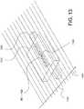
- FIG. 14 there is illustrated a sensor assembly according to the present invention on which the present technology is based corresponding to a sensor array including three sensors HE1, HE2, HE3 mounted along a common line and configured to produce separate output signals.
- sensors HE1, HE2, HE3 are surface mount chip type Hall effect devices and are mounted on a common substrate (not separately illustrated) affixed to circuit board 1410, It should be appreciated, however, that other types of sensors may be used.
- a permanent magnet 1420 is associated with printed circuit board 1410 and sensors HE1, HE2, HE3 and is positioned so that the north and south poles of the permanent magnet are aligned with the common line on which the sensors HE1, HE2, HE3 are mounted.
- magnet 1420 may correspond to a pair of 1 ⁇ 4" by 1 ⁇ 4" by 1" N50 neodymium magnets placed end to end with complimentary poles in effect creating one 2" long magnet.
- sensors HE1 and HE2 are considered as a first pair while sensors HE2 and HE3 are considered as a second pair.
- This configuration enables doubling the surface area covered in a single pass of the sensor assembly to reduce the total testing cycle time.
- the signal processing is handled in a manner similar to previously discussed embodiments with reference to Figure 3 in that fixed pairing of sensors are maintained while scanning for damaged tire cables including, for example, break 1430 in cable 1432 while the sensor and magnet assembly scanned generally in the direction of arrow 1434 over the multiple cables collectively illustrated as cables 1440.
- Figure 7 flux lines produced from a permanent magnet resulting from spacing a pair of sensors HE1, HE2 such that the sensor centers are centered directly over each end 702, 704 of a single complete tire cable break 706.
- Figure 8 illustrates a plot of flux magnitude, highlighting by illustrated arrows 802, 804, exemplary readings when the centers of the sensors are placed over each end 702, 704 of single complete tire cable break 706.
- the maximum flux leakage is centered directly over each end 702, 704 of the damage.
- Figures 9 and 10 illustrate the first problem identified above, i.e., that of one sensor HE1 being lined up with an area of cable damage 906 as opposed to over one of the cable break ends 902, 904.
- arrows 1002 and 1004 respectively, indicate the flux magnitude at the center of each sensor HE1, HE2 as located as illustrated in Figure 9
- neither sensor will detect the full leakage available due to being positioned off center from the optimum placement over the ends of the damage as previously illustrated in Figure 7 .
- center-to-center spacing was set at 10 mm. In such instance, smaller damages are likely to pass off center and far away from the optimum location for each sensor. While the damage may be close enough to one sensor to provide the appropriate flux leakage indication, it is possible for the other sensor to be so far away from the edge of the damage that it will have no indication of flux leakage. With the exemplary 10 mm spacing noted, the spacing would be optimal only if the damage was 10 mm in width.
- the present technology provides for two variations that together operate synergistically to provide improved anomaly detection.
- six surface mount chip type magnetic sensors HE1 - HE6 are placed along a common line on a printed circuit board 1310.
- the six surface mount chip type magnetic sensors HE1 - HE6 may be positioned on a 4 mm center to center spacing resulting in an overall length for the array of about 20 mm.
- Magnet 1320 is associated with the sensor array by being placed along the same common line on which the sensors HE1-HE6 are placed in a manner similar to that previously described with reference to Figure 14 .
- the chip type magnetic sensors HE1 - HE6 and magnet 1320 may correspond to magnet 1420 as described with relation to Figure 14 .
- a second physically identical six-sensor array may be place in parallel with the first array and positioned such that the space between sensors in the second array falls between the space between sensors in the first array.
- Such positioning with appropriate adjustments to the signal processing system would effectively cut in half the spacing between sensors.
- This concept could be extended to a third, fourth, etc. parallel sensor array.
- a six sensor array of sensors HE1, HE2, HE3, HE4, HE5, and HE6 provides fifteen pairs of sensors as follows: TABLE 1 HE1 HE2 HE1 HE3 HE1 HE4 HE1 HE5 HE1 HE6 HE2 HE3 HE2 HE4 HE2 HE5 HE2 HE6 HE3 HE4 HE3 HE5 HE3 HE6 HE4 HE5 HE4 HE6 HE5 HE6 HE5 HE6 HE5 HE6 HE5 HE6 HE5 HE6
- each sensors' output signal magnitude is evaluated and the strongest positive flux leakage detection signal is paired with the strongest opposing, i.e., negative, flux leakage detection signal to provide the "pair" that produces a resultant damage magnitude signal to the exclusion of the remaining signals for that particular portion, i.e., azimuth of the tire.
- the highest positive signal is paired with the highest negative signal and the remaining signals are ignored.
- signals similar to the positive going signal at 502 and the negative going signal at 504 would be selected to be paired while the lesser illustrated signals would be ignored.
Landscapes
- Chemical & Material Sciences (AREA)
- Chemical Kinetics & Catalysis (AREA)
- Electrochemistry (AREA)
- Physics & Mathematics (AREA)
- Health & Medical Sciences (AREA)
- Life Sciences & Earth Sciences (AREA)
- Analytical Chemistry (AREA)
- Biochemistry (AREA)
- General Health & Medical Sciences (AREA)
- General Physics & Mathematics (AREA)
- Immunology (AREA)
- Pathology (AREA)
- Investigating Or Analyzing Materials By The Use Of Magnetic Means (AREA)
- Geophysics And Detection Of Objects (AREA)
- Measuring Magnetic Variables (AREA)
Claims (13)
- Vorrichtung zur Erkennung von Anomalien (402, 404, 406) in einem Reifenmetalldraht, wobei die Vorrichtung umfasst:mehrere Magnetfeldsensoren, die entlang einer gemeinsamen Linie (110) positioniert und konfiguriert sind, um individuelle elektrische Signale, die proportional zu einem erfassten magnetischen Feld sind, zu erzeugen;einen Magneten (102), der Nord- und Südpole desselben aufweist, die positioniert sind, um ein magnetisches Feld an jedem der mehreren Magnetfeldsensoren parallel zu der gemeinsamen Linie (110) bereitzustellen; undeinen Signalverarbeitungsschaltkreis, der konfiguriert ist, um Signale zu erzeugen, die einen Hinweis auf Unterschiede zwischen Paaren der individuellen elektrischen Signale angeben,wobei das elektrische Signal von jedem der mehreren Magnetfeldsensoren gepaart ist mit einem elektrischen Signal von jedem der anderen von den mehreren Magnetfeldsensoren,dadurch gekennzeichnet, dass die mehreren Magnetfeldsensoren mindestens drei Magnetfeldsensoren umfassen und dass dabei alle Kombinationen von Sensoren in Erwägung gezogen werden.
- Vorrichtung nach Anspruch 1, wobei die mehreren Magnetfeldsensoren oberflächenbefestigte Hall-Effekt-Sensoren (HE1 bis HE6) umfassen.
- Vorrichtung nach Anspruch 1, wobei der Signalverarbeitungsschaltkreis konfiguriert ist, das stärkste elektrische Signal mit dem stärksten, entgegengesetzten, elektrischen Signal zu paaren, um ein Schadensgrößensignal zu erzeugen, während die verbleibenden elektrischen Signale nicht beachtet werden.
- Vorrichtung nach Anspruch 1, wobei der Signalverarbeitungsschaltkreis konfiguriert ist, ein Signal auf der Grundlage von subtraktiven Signalunterschieden oder des Vorhandenseins von entgegengesetzt geneigten Signalen mit Neigungen, von denen jede eine vorgegebene Größe überschreitet, oder auf Grundlage einer Faltungsanalyse von mit Null gemittelten vervielfachten Wellenformen zu erzeugen.
- Vorrichtung nach Anspruch 1, die ferner umfasst:
eine Struktur (104), die konfiguriert ist, die mehreren Magnetfeldsensoren und den Magneten zu tragen, wodurch die mehreren Magnetfeldsensoren an einen Metalldraht (320, 420) für eine Erkennung von Anomalien an demselben manuell angelegt werden können. - Vorrichtung nach Anspruch 1, die ferner umfasst:
ein automatisches Steuersystem (120), das konfiguriert ist, die mehreren Magnetfeldsensoren an einen Metalldraht für eine Erkennung von Anomalien an demselben automatisch anzulegen. - Vorrichtung nach Anspruch 1, wobei der Magnet ein Permanentmagnet (102) ist.
- Verfahren zur Erkennung von Anomalien in einem Reifenmetalldraht, das umfasst:
Positionieren mehrerer Magnetfeldsensoren auf einer gemeinsamen Linie (110); Positionieren eines Magneten, der Nord- und Südpole desselben aufweist, um ein magnetisches Feld an jedem der mehreren Magnetfeldsensoren parallel zu der gemeinsamen Linie (110) bereitzustellen; Anlegen der mehreren Magnetfeldsensoren an einen Metalldraht; und Erkennen eines Unterschieds zwischen Signalen, die von jedem der mehreren Magnetfeldsensoren, die mit jedem der anderen von den mehreren Magnetfeldsensoren gepaart sind, erzeugt werden, dadurch gekennzeichnet, dass das Positionieren von mehreren Magnetfeldsensoren ein Positionieren von mindestens drei Magnetfeldsensoren umfasst, und dass dabei alle Kombinationen der Sensoren in Erwägung gezogen werden. - Verfahren nach Anspruch 8, das ferner umfasst:
Paaren des stärksten, positiven Signals von jedem der mehreren Magnetfeldsensoren mit dem stärksten, negativen Signal von jedem der anderen Magnetfeldsensoren; und Analysieren des Unterschieds zwischen dem stärksten, positiven Signal und dem stärksten, negativen Signal hinsichtlich des Ausschlusses der verbleibenden Signale der Magnetfeldsensoren. - Verfahren nach Anspruch 8, wobei ein Erkennen eines Unterschieds zwischen Signalen ein Erzeugen eines Signals auf der Grundlage von subtraktiven Signalunterschieden oder des Vorhandenseins von entgegengesetzt geneigten Signalen mit Neigungen, von denen jede eine vorgegebene Größe überschreitet, oder auf Grundlage einer Faltungsanalyse von mit Null gemittelten vervielfachten Wellenformen umfasst.
- Verfahren nach Anspruch 8, wobei ein Positionieren von Magnetfeldsensoren ein Positionieren von oberflächenbefestigten Hall-Effekt-Sensoren (HE1 bis HE6) umfasst.
- Verfahren nach Anspruch 8, wobei ein Positionieren eines Magneten ein Positionieren sowohl des Nord- als auch des Südpols eines Magneten entlang einer Linie umfasst, die parallel zu der gemeinsamen Linie ist.
- Verfahren nach Anspruch 8, wobei ein Positionieren eines Magneten ein Positionieren eines Permanentmagneten (102) umfasst.
Applications Claiming Priority (2)
| Application Number | Priority Date | Filing Date | Title |
|---|---|---|---|
| PCT/US2009/040017 WO2010117363A1 (en) | 2009-04-09 | 2009-04-09 | Tire metallic cable anomaly detection method and apparatus |
| PCT/US2010/029390 WO2010117855A1 (en) | 2009-04-09 | 2010-03-31 | Tire metallic cable anomaly detection method and apparatus |
Publications (3)
| Publication Number | Publication Date |
|---|---|
| EP2417433A1 EP2417433A1 (de) | 2012-02-15 |
| EP2417433A4 EP2417433A4 (de) | 2015-05-20 |
| EP2417433B1 true EP2417433B1 (de) | 2018-10-24 |
Family
ID=42936463
Family Applications (1)
| Application Number | Title | Priority Date | Filing Date |
|---|---|---|---|
| EP10762216.9A Active EP2417433B1 (de) | 2009-04-09 | 2010-03-31 | Verfahren und vorrichtung zur erkennung von anomalien in reifenmetalldrähten |
Country Status (9)
| Country | Link |
|---|---|
| US (1) | US9442093B2 (de) |
| EP (1) | EP2417433B1 (de) |
| JP (1) | JP5547801B2 (de) |
| CN (1) | CN102439411B (de) |
| AU (1) | AU2010234750B2 (de) |
| BR (1) | BRPI1014969A8 (de) |
| CA (1) | CA2757294C (de) |
| MX (1) | MX2011010520A (de) |
| WO (2) | WO2010117363A1 (de) |
Families Citing this family (24)
| Publication number | Priority date | Publication date | Assignee | Title |
|---|---|---|---|---|
| US8994817B2 (en) * | 2011-11-14 | 2015-03-31 | Michelin Recherche Et Technique S.A. | Infrared inspection of metallic web structures |
| US9470657B2 (en) | 2012-10-04 | 2016-10-18 | Her Majesty The Queen In Right Of Canada As Represented By The Minister Of Natural Resources Canada | Measurement of lay length of wire rope |
| FR3003039B1 (fr) * | 2013-03-08 | 2015-03-06 | Commissariat Energie Atomique | Procede de reconnaissance automatique d'un objet magnetique |
| EP3117199B1 (de) | 2014-03-13 | 2019-03-13 | Compagnie Générale des Etablissements Michelin | Sensorvorrichtung zur reifeninspektion |
| CN105980823B (zh) * | 2014-03-13 | 2018-08-28 | 米其林集团总公司 | 具有磁体的传感器装置和用于轮胎检查的传感器阵列 |
| US10168300B2 (en) * | 2014-08-28 | 2019-01-01 | Compagnie Generale Des Etablissements Michelin | Magnetic flux sensor quality indicator apparatus and method |
| WO2016080947A1 (en) * | 2014-11-17 | 2016-05-26 | Halliburton Energy Services, Inc. | Rapid magnetic hotspot detector |
| WO2016101032A1 (en) | 2014-12-24 | 2016-06-30 | Technological Resources Pty Ltd | A system for detecting a break in a rail |
| WO2016111671A1 (en) * | 2015-01-05 | 2016-07-14 | Compagnie Generale Des Etablissements Michelin | Multiple row sensing device for a tire |
| WO2016111672A1 (en) * | 2015-01-05 | 2016-07-14 | Compagnie Generale Des Etablissements Michelin | Method of using multiple row sensing device for a tire |
| WO2016175783A1 (en) * | 2015-04-29 | 2016-11-03 | Compagnie Generale Des Etablissements Michelin | Sensing device with proximity detection for tire inspection |
| US20180172865A1 (en) * | 2016-12-19 | 2018-06-21 | Boston Scientific Scimed Inc. | Dominant axis navigation sensor |
| US11058321B2 (en) | 2016-12-20 | 2021-07-13 | Boston Scientific Scimed Inc. | Current driven sensor for magnetic navigation |
| CL2016003404A1 (es) * | 2016-12-30 | 2017-12-15 | Univ De Santiago De Chile Usach | Un sistema autónomo de monitoreo basado en variación de campo magnético, que permite predecir, prevenir y detectar en tiempo real material inchancable, tal como metal y/o material de “minería vieja” o faenas anteriores y/o partes o piezas de los equipos de minería, todos los anteriores cuerpos metálicos extraños e inchancables, para equipos de extracción minera y/o de carga; método de instalación; método de operación; y diente, elemento de desgaste o parte de un equipo de extracción minera y/o de carga, q |
| US10835151B2 (en) | 2017-02-06 | 2020-11-17 | Boston Scientific Scimed Inc. | Sensor assemblies for electromagnetic navigation systems |
| US11175262B2 (en) | 2017-06-30 | 2021-11-16 | Compagnie Generale Des Etablissements Michelin | Method for inspection of polymeric material with ferrous reinforcement to determine presence of reinforcement joint or damage |
| CN108760775B (zh) * | 2018-06-08 | 2021-03-19 | 国宏中晶集团有限公司 | 一种废旧轮胎的物料核算装置及方法 |
| US11092629B2 (en) * | 2018-08-27 | 2021-08-17 | Sacramento Municipal Utility District | Techniques for analysis of data from smart meters |
| EP3990267B1 (de) | 2019-06-27 | 2024-04-17 | Compagnie Generale Des Etablissements Michelin | Anordnung zum positionieren von sensoren in einem reifen |
| EP4042132B1 (de) * | 2019-10-08 | 2025-12-17 | Bridgestone Americas Tire Operations, LLC | Magnetisches überfahrystem zur messung der dicke/tiefe von reifenlaufflächen |
| WO2021251129A1 (ja) * | 2020-06-09 | 2021-12-16 | 国立大学法人大阪大学 | 磁性体検査装置、及び、磁性体検査方法 |
| US12117290B2 (en) | 2020-06-25 | 2024-10-15 | Compagnie Generale Des Etablissements Michelin | Method for the detection of cable spacing in green tire |
| US12163922B2 (en) * | 2021-03-29 | 2024-12-10 | Spscanco Llc | Metallic flaw detection system and method |
| US20250076362A1 (en) * | 2023-09-01 | 2025-03-06 | Florida State University Research Foundation, Inc. | Systems and methods for detecting defects in cables |
Family Cites Families (47)
| Publication number | Priority date | Publication date | Assignee | Title |
|---|---|---|---|---|
| US2345679A (en) | 1939-08-22 | 1944-04-04 | Harry J Linse | Method of testing pneumatic tire casings |
| US3604249A (en) | 1968-06-21 | 1971-09-14 | Massachusetts Inst Technology | Method and apparatus for testing pneumatic tire casings |
| US3815407A (en) | 1973-01-22 | 1974-06-11 | Department Of Transportation | Resonance tire inspection method and apparatus |
| JPS5278283A (en) | 1975-12-25 | 1977-07-01 | Fuji Electric Co Ltd | Tire inspecting device using radio active ray |
| DE7824207U1 (de) | 1978-08-12 | 1979-02-01 | Continental Gummi-Werke Ag, 3000 Hannover | Vorrichtung zum pruefen von fahrzeugluftreifen |
| US4285235A (en) | 1979-04-19 | 1981-08-25 | Bandag Incorporated | Method and apparatus for non-destructive inspection of tires |
| CA1166696A (en) | 1979-07-29 | 1984-05-01 | Thomas J. Daley-Hall | Non-destructive testing of ferromagnetic articles |
| DE3132808C2 (de) * | 1981-08-19 | 1984-01-26 | Nukem Gmbh, 6450 Hanau | "Vorrichtung zur zerstörungsfreien Prüfung ferromagnetischer Körper" |
| JPS5939538B2 (ja) | 1981-10-27 | 1984-09-25 | 耕一 浜田 | 端部に掛環を有するロ−プ平ベルト |
| US4659991A (en) * | 1983-03-31 | 1987-04-21 | Ndt Technologies, Inc. | Method and apparatus for magnetically inspecting elongated objects for structural defects |
| JPS59217158A (ja) | 1983-05-26 | 1984-12-07 | Mitsubishi Electric Corp | 欠陥検出装置 |
| US4785354A (en) | 1984-12-28 | 1988-11-15 | Bridgestone Corporation | Tire load test CT scanner |
| GB2203549B (en) | 1987-04-15 | 1991-05-01 | Julian Marsden Carroll | Metal corrosion detection |
| US5060136A (en) | 1989-01-06 | 1991-10-22 | International Business Machines Corp. | Four-way associative cache with dlat and separately addressable arrays used for updating certain bits without reading them out first |
| US5060250A (en) | 1990-03-06 | 1991-10-22 | The Goodyear Tire & Rubber Company | Method and system for detecting defects in tire sidewalls |
| JPH04341835A (ja) | 1991-05-17 | 1992-11-27 | Bridgestone Corp | 更生タイヤ用スカイブ装置 |
| EP0543648A1 (de) * | 1991-11-21 | 1993-05-26 | Kaisei Engineer Co., Ltd. | Inspektionsvorrichtung und Methode unter Verwendung elektromagnetischer Induktion |
| DK0548439T3 (da) * | 1991-12-18 | 1996-02-19 | Flowtec Ag | Omskifterindretning til drift af flere magnetiskinduktive flowfølere til en enkelt elektronisk evalu eringsenhed |
| DE4223248A1 (de) | 1992-07-15 | 1994-01-20 | Continental Ag | Verfahren zum Erkennen von Fehlstellen in Stahlcordmaterial |
| JPH07253448A (ja) | 1994-03-14 | 1995-10-03 | Tokyo Seiko Co Ltd | スチールコードの断線検出装置 |
| FR2719667B1 (fr) | 1994-05-04 | 1996-07-26 | Laurent Pneu | Procédé et dispositif de contrôle électromagnétique de pneumatiques usagés. |
| US5565771A (en) | 1995-01-18 | 1996-10-15 | Noranda, Inc. | Apparatus for increasing linear resolution of electromagnetic wire rope testing |
| DE59602900D1 (de) * | 1995-10-13 | 1999-09-30 | Wolf Geraete Gmbh Vertrieb | Aufsitzrasenmäher |
| JPH09188496A (ja) * | 1995-11-09 | 1997-07-22 | Sumitomo Constr Mach Co Ltd | ワイヤロープ損傷検出装置 |
| DE19621198C1 (de) * | 1996-05-25 | 1997-08-21 | Continental Ag | Vorrichtung und Verfahren zur Ermittlung von Fehlern in der Anordnung von Festigkeitsträgern aus magnetisierbarem Material in Karkassenlagen im Seitenwandbereich eines Reifens |
| JP3127842B2 (ja) | 1996-11-01 | 2001-01-29 | ダイキン工業株式会社 | カムモータ装置 |
| US5804964A (en) * | 1996-11-29 | 1998-09-08 | Noranda Inc. | Wire rope damage index monitoring device |
| GB2324155A (en) | 1997-04-09 | 1998-10-14 | Univ Keele | Method and apparatus for scanning a magnetic structure |
| JP3504114B2 (ja) | 1997-07-29 | 2004-03-08 | シャープ株式会社 | 回路内蔵受光素子 |
| JPH11248684A (ja) | 1998-03-03 | 1999-09-17 | Daido Steel Co Ltd | 渦流探傷装置 |
| US6141387A (en) * | 1998-03-19 | 2000-10-31 | Motorola, Inc. | Digital QAM modulator using post filtering carrier recombination |
| DE19849793C1 (de) | 1998-10-28 | 2000-03-16 | Fraunhofer Ges Forschung | Vorrichtung und Verfahren zur berührungslosen Erfassung von Unebenheiten in einer gewölbten Oberfläche |
| US6304090B1 (en) | 1999-10-22 | 2001-10-16 | Arnold A. Weiss | High voltage tire testing apparatus |
| USRE40166E1 (en) * | 1999-12-17 | 2008-03-25 | Intron Plus, Ltd. | Magnetic non-destructive method and apparatus for measurement of cross sectional area and detection of local flaws in elongated ferrous objects in response to longitudinally spaced sensors in an inter-pole area |
| WO2003017535A1 (en) * | 2000-07-28 | 2003-02-27 | Litton Systems, Inc. | Multi-channel optical receiver for processing tri-cell polarization diversity detector outputs |
| GB0211663D0 (en) | 2002-05-21 | 2002-07-03 | Transense Technologies Plc | Tyre sensor interrogation |
| JPWO2003100370A1 (ja) * | 2002-05-24 | 2005-09-22 | 株式会社ブリヂストン | タイヤ温度センサおよびタイヤ熱劣化検知センサならびにタイヤ |
| FR2860878B1 (fr) * | 2003-10-08 | 2006-02-17 | Centre Nat Etd Spatiales | Sonde de mesure d'un champ magnetique. |
| US7082819B2 (en) * | 2003-12-09 | 2006-08-01 | Michelin Recherche Et Technique S.A. | Doppler radar for detecting tire abnormalities |
| JP4774690B2 (ja) | 2004-06-24 | 2011-09-14 | Jfeスチール株式会社 | 磁気センサ |
| WO2006067361A1 (en) | 2004-12-24 | 2006-06-29 | Keele University | A method and apparatus for testing the integrity of a magnetic structure |
| US7185534B2 (en) | 2005-08-03 | 2007-03-06 | The Goodyear Tire & Rubber Company | Ply wire sensor system for a tire |
| US7416624B2 (en) * | 2005-08-03 | 2008-08-26 | The Goodyear Tire & Rubber Company | Method for evaluating ply wire anomalies in a tire |
| JP5088006B2 (ja) | 2007-06-14 | 2012-12-05 | 横浜ゴム株式会社 | タイヤの検査方法及びその装置 |
| JP5088005B2 (ja) | 2007-06-14 | 2012-12-05 | 横浜ゴム株式会社 | タイヤの検査方法及びその装置 |
| JP4858711B2 (ja) | 2007-06-14 | 2012-01-18 | 横浜ゴム株式会社 | タイヤの検査方法及びその装置 |
| CN101266226A (zh) | 2008-05-14 | 2008-09-17 | 哈尔滨工业大学 | 子午胎钢丝帘线缺陷的永磁激磁磁场畸变检测探头及方法 |
-
2009
- 2009-04-09 WO PCT/US2009/040017 patent/WO2010117363A1/en not_active Ceased
-
2010
- 2010-03-31 US US13/260,744 patent/US9442093B2/en active Active
- 2010-03-31 CN CN201080022614.XA patent/CN102439411B/zh active Active
- 2010-03-31 AU AU2010234750A patent/AU2010234750B2/en not_active Ceased
- 2010-03-31 EP EP10762216.9A patent/EP2417433B1/de active Active
- 2010-03-31 BR BRPI1014969A patent/BRPI1014969A8/pt not_active IP Right Cessation
- 2010-03-31 MX MX2011010520A patent/MX2011010520A/es active IP Right Grant
- 2010-03-31 JP JP2012504711A patent/JP5547801B2/ja not_active Expired - Fee Related
- 2010-03-31 WO PCT/US2010/029390 patent/WO2010117855A1/en not_active Ceased
- 2010-03-31 CA CA2757294A patent/CA2757294C/en not_active Expired - Fee Related
Non-Patent Citations (1)
| Title |
|---|
| None * |
Also Published As
| Publication number | Publication date |
|---|---|
| US20120038357A1 (en) | 2012-02-16 |
| BRPI1014969A8 (pt) | 2018-01-02 |
| BRPI1014969A2 (pt) | 2016-04-26 |
| CN102439411A (zh) | 2012-05-02 |
| AU2010234750B2 (en) | 2013-02-21 |
| MX2011010520A (es) | 2011-10-28 |
| EP2417433A4 (de) | 2015-05-20 |
| CA2757294C (en) | 2014-04-08 |
| US9442093B2 (en) | 2016-09-13 |
| CA2757294A1 (en) | 2010-10-14 |
| CN102439411B (zh) | 2015-08-19 |
| JP5547801B2 (ja) | 2014-07-16 |
| EP2417433A1 (de) | 2012-02-15 |
| WO2010117855A1 (en) | 2010-10-14 |
| WO2010117363A1 (en) | 2010-10-14 |
| JP2012523566A (ja) | 2012-10-04 |
| AU2010234750A1 (en) | 2011-11-03 |
Similar Documents
| Publication | Publication Date | Title |
|---|---|---|
| EP2417433B1 (de) | Verfahren und vorrichtung zur erkennung von anomalien in reifenmetalldrähten | |
| US5914596A (en) | Coiled tubing inspection system | |
| US6636037B1 (en) | Super sensitive eddy-current electromagnetic probe system and method for inspecting anomalies in conducting plates | |
| US9213018B2 (en) | Partial saturation eddy current sensor apparatus and method of use | |
| Betta et al. | GMR-based ECT instrument for detection and characterization of crack on a planar specimen: A hand-held solution | |
| US7505859B2 (en) | Method and algorithms for inspection of longitudinal defects in an eddy current inspection system | |
| CN101893601B (zh) | 用于感应测量的装置和方法 | |
| CN106574912A (zh) | 用于漏损通量检验的方法和装置 | |
| US8988071B2 (en) | Nondestructive inspection of a structure in an aircraft | |
| KR20090115099A (ko) | 자기 센서 어레이 | |
| CN102759567A (zh) | 直流磁化下钢管内外壁缺陷的涡流检测识别及评价方法 | |
| CN102435668B (zh) | 基于漏磁场双分量的阵列型铁磁构件表面缺陷探测器 | |
| CN108956756A (zh) | 一种高灵敏铁磁材料无损检测方法及系统 | |
| WO1998016842A1 (en) | Coiled tubing inspection system | |
| CN106707206A (zh) | 基于gmr效应的金属磁记忆三轴阵列传感器 | |
| US7304474B2 (en) | Eddy current inspection device with arrays of magnetoresistive sensors | |
| US10777031B2 (en) | Coin detection system | |
| JPH04221757A (ja) | 欠陥検出装置及び方法 | |
| RU93539U1 (ru) | Устройство для измерения параметров магнитного поля | |
| US9310337B2 (en) | Non-destructive inspection device for pressure containers using leakage-flux measurement | |
| US20060202688A1 (en) | Detection system and method thereof | |
| Yamada et al. | Metallic Bead Detection by Using Eddy‐Current Probe with SV‐GMR Sensor | |
| Postolache et al. | New architectures of uniform eddy current probes for NDT using GMR | |
| Wincheski et al. | Flux-focusing eddy current probe and rotating probe method for flaw detection |
Legal Events
| Date | Code | Title | Description |
|---|---|---|---|
| PUAI | Public reference made under article 153(3) epc to a published international application that has entered the european phase |
Free format text: ORIGINAL CODE: 0009012 |
|
| 17P | Request for examination filed |
Effective date: 20110930 |
|
| AK | Designated contracting states |
Kind code of ref document: A1 Designated state(s): AT BE BG CH CY CZ DE DK EE ES FI FR GB GR HR HU IE IS IT LI LT LU LV MC MK MT NL NO PL PT RO SE SI SK SM TR |
|
| DAX | Request for extension of the european patent (deleted) | ||
| RAP1 | Party data changed (applicant data changed or rights of an application transferred) |
Owner name: COMPAGNIE GENERALE DES ETABLISSEMENTS MICHELIN Owner name: MICHELIN RECHERCHE ET TECHNIQUE S.A. |
|
| RA4 | Supplementary search report drawn up and despatched (corrected) |
Effective date: 20150420 |
|
| RIC1 | Information provided on ipc code assigned before grant |
Ipc: G01N 27/82 20060101ALI20150414BHEP Ipc: G01M 17/02 20060101AFI20150414BHEP |
|
| 17Q | First examination report despatched |
Effective date: 20160705 |
|
| STAA | Information on the status of an ep patent application or granted ep patent |
Free format text: STATUS: EXAMINATION IS IN PROGRESS |
|
| RAP1 | Party data changed (applicant data changed or rights of an application transferred) |
Owner name: MICHELIN RECHERCHE ET TECHNIQUE S.A. |
|
| RAP1 | Party data changed (applicant data changed or rights of an application transferred) |
Owner name: COMPAGNIE GENERALE DES ETABLISSEMENTS MICHELIN |
|
| GRAP | Despatch of communication of intention to grant a patent |
Free format text: ORIGINAL CODE: EPIDOSNIGR1 |
|
| STAA | Information on the status of an ep patent application or granted ep patent |
Free format text: STATUS: GRANT OF PATENT IS INTENDED |
|
| INTG | Intention to grant announced |
Effective date: 20180516 |
|
| RIN1 | Information on inventor provided before grant (corrected) |
Inventor name: BRANDON, LEE Inventor name: JUDD, DAVID, ANDREW Inventor name: DEAMICIS, GENE, EDWARD Inventor name: GRAMLING, FRANK, E. |
|
| GRAS | Grant fee paid |
Free format text: ORIGINAL CODE: EPIDOSNIGR3 |
|
| GRAA | (expected) grant |
Free format text: ORIGINAL CODE: 0009210 |
|
| STAA | Information on the status of an ep patent application or granted ep patent |
Free format text: STATUS: THE PATENT HAS BEEN GRANTED |
|
| GRAT | Correction requested after decision to grant or after decision to maintain patent in amended form |
Free format text: ORIGINAL CODE: EPIDOSNCDEC |
|
| AK | Designated contracting states |
Kind code of ref document: B1 Designated state(s): AT BE BG CH CY CZ DE DK EE ES FI FR GB GR HR HU IE IS IT LI LT LU LV MC MK MT NL NO PL PT RO SE SI SK SM TR |
|
| REG | Reference to a national code |
Ref country code: GB Ref legal event code: FG4D |
|
| RAP2 | Party data changed (patent owner data changed or rights of a patent transferred) |
Owner name: COMPAGNIE GENERALE DES ETABLISSEMENTS MICHELIN |
|
| REG | Reference to a national code |
Ref country code: CH Ref legal event code: EP |
|
| REG | Reference to a national code |
Ref country code: IE Ref legal event code: FG4D |
|
| REG | Reference to a national code |
Ref country code: AT Ref legal event code: REF Ref document number: 1057267 Country of ref document: AT Kind code of ref document: T Effective date: 20181115 |
|
| REG | Reference to a national code |
Ref country code: DE Ref legal event code: R096 Ref document number: 602010054599 Country of ref document: DE |
|
| REG | Reference to a national code |
Ref country code: NL Ref legal event code: FP |
|
| REG | Reference to a national code |
Ref country code: LT Ref legal event code: MG4D |
|
| REG | Reference to a national code |
Ref country code: AT Ref legal event code: MK05 Ref document number: 1057267 Country of ref document: AT Kind code of ref document: T Effective date: 20181024 |
|
| PG25 | Lapsed in a contracting state [announced via postgrant information from national office to epo] |
Ref country code: IS Free format text: LAPSE BECAUSE OF FAILURE TO SUBMIT A TRANSLATION OF THE DESCRIPTION OR TO PAY THE FEE WITHIN THE PRESCRIBED TIME-LIMIT Effective date: 20190224 Ref country code: PL Free format text: LAPSE BECAUSE OF FAILURE TO SUBMIT A TRANSLATION OF THE DESCRIPTION OR TO PAY THE FEE WITHIN THE PRESCRIBED TIME-LIMIT Effective date: 20181024 Ref country code: NO Free format text: LAPSE BECAUSE OF FAILURE TO SUBMIT A TRANSLATION OF THE DESCRIPTION OR TO PAY THE FEE WITHIN THE PRESCRIBED TIME-LIMIT Effective date: 20190124 Ref country code: HR Free format text: LAPSE BECAUSE OF FAILURE TO SUBMIT A TRANSLATION OF THE DESCRIPTION OR TO PAY THE FEE WITHIN THE PRESCRIBED TIME-LIMIT Effective date: 20181024 Ref country code: BG Free format text: LAPSE BECAUSE OF FAILURE TO SUBMIT A TRANSLATION OF THE DESCRIPTION OR TO PAY THE FEE WITHIN THE PRESCRIBED TIME-LIMIT Effective date: 20190124 Ref country code: ES Free format text: LAPSE BECAUSE OF FAILURE TO SUBMIT A TRANSLATION OF THE DESCRIPTION OR TO PAY THE FEE WITHIN THE PRESCRIBED TIME-LIMIT Effective date: 20181024 Ref country code: LT Free format text: LAPSE BECAUSE OF FAILURE TO SUBMIT A TRANSLATION OF THE DESCRIPTION OR TO PAY THE FEE WITHIN THE PRESCRIBED TIME-LIMIT Effective date: 20181024 Ref country code: LV Free format text: LAPSE BECAUSE OF FAILURE TO SUBMIT A TRANSLATION OF THE DESCRIPTION OR TO PAY THE FEE WITHIN THE PRESCRIBED TIME-LIMIT Effective date: 20181024 Ref country code: AT Free format text: LAPSE BECAUSE OF FAILURE TO SUBMIT A TRANSLATION OF THE DESCRIPTION OR TO PAY THE FEE WITHIN THE PRESCRIBED TIME-LIMIT Effective date: 20181024 Ref country code: FI Free format text: LAPSE BECAUSE OF FAILURE TO SUBMIT A TRANSLATION OF THE DESCRIPTION OR TO PAY THE FEE WITHIN THE PRESCRIBED TIME-LIMIT Effective date: 20181024 |
|
| PG25 | Lapsed in a contracting state [announced via postgrant information from national office to epo] |
Ref country code: PT Free format text: LAPSE BECAUSE OF FAILURE TO SUBMIT A TRANSLATION OF THE DESCRIPTION OR TO PAY THE FEE WITHIN THE PRESCRIBED TIME-LIMIT Effective date: 20190224 Ref country code: SE Free format text: LAPSE BECAUSE OF FAILURE TO SUBMIT A TRANSLATION OF THE DESCRIPTION OR TO PAY THE FEE WITHIN THE PRESCRIBED TIME-LIMIT Effective date: 20181024 Ref country code: GR Free format text: LAPSE BECAUSE OF FAILURE TO SUBMIT A TRANSLATION OF THE DESCRIPTION OR TO PAY THE FEE WITHIN THE PRESCRIBED TIME-LIMIT Effective date: 20190125 |
|
| REG | Reference to a national code |
Ref country code: DE Ref legal event code: R097 Ref document number: 602010054599 Country of ref document: DE |
|
| PG25 | Lapsed in a contracting state [announced via postgrant information from national office to epo] |
Ref country code: IT Free format text: LAPSE BECAUSE OF FAILURE TO SUBMIT A TRANSLATION OF THE DESCRIPTION OR TO PAY THE FEE WITHIN THE PRESCRIBED TIME-LIMIT Effective date: 20181024 Ref country code: DK Free format text: LAPSE BECAUSE OF FAILURE TO SUBMIT A TRANSLATION OF THE DESCRIPTION OR TO PAY THE FEE WITHIN THE PRESCRIBED TIME-LIMIT Effective date: 20181024 Ref country code: CZ Free format text: LAPSE BECAUSE OF FAILURE TO SUBMIT A TRANSLATION OF THE DESCRIPTION OR TO PAY THE FEE WITHIN THE PRESCRIBED TIME-LIMIT Effective date: 20181024 |
|
| PG25 | Lapsed in a contracting state [announced via postgrant information from national office to epo] |
Ref country code: RO Free format text: LAPSE BECAUSE OF FAILURE TO SUBMIT A TRANSLATION OF THE DESCRIPTION OR TO PAY THE FEE WITHIN THE PRESCRIBED TIME-LIMIT Effective date: 20181024 Ref country code: SK Free format text: LAPSE BECAUSE OF FAILURE TO SUBMIT A TRANSLATION OF THE DESCRIPTION OR TO PAY THE FEE WITHIN THE PRESCRIBED TIME-LIMIT Effective date: 20181024 Ref country code: EE Free format text: LAPSE BECAUSE OF FAILURE TO SUBMIT A TRANSLATION OF THE DESCRIPTION OR TO PAY THE FEE WITHIN THE PRESCRIBED TIME-LIMIT Effective date: 20181024 Ref country code: SM Free format text: LAPSE BECAUSE OF FAILURE TO SUBMIT A TRANSLATION OF THE DESCRIPTION OR TO PAY THE FEE WITHIN THE PRESCRIBED TIME-LIMIT Effective date: 20181024 |
|
| PLBE | No opposition filed within time limit |
Free format text: ORIGINAL CODE: 0009261 |
|
| STAA | Information on the status of an ep patent application or granted ep patent |
Free format text: STATUS: NO OPPOSITION FILED WITHIN TIME LIMIT |
|
| 26N | No opposition filed |
Effective date: 20190725 |
|
| PG25 | Lapsed in a contracting state [announced via postgrant information from national office to epo] |
Ref country code: SI Free format text: LAPSE BECAUSE OF FAILURE TO SUBMIT A TRANSLATION OF THE DESCRIPTION OR TO PAY THE FEE WITHIN THE PRESCRIBED TIME-LIMIT Effective date: 20181024 Ref country code: MC Free format text: LAPSE BECAUSE OF FAILURE TO SUBMIT A TRANSLATION OF THE DESCRIPTION OR TO PAY THE FEE WITHIN THE PRESCRIBED TIME-LIMIT Effective date: 20181024 |
|
| REG | Reference to a national code |
Ref country code: CH Ref legal event code: PL |
|
| GBPC | Gb: european patent ceased through non-payment of renewal fee |
Effective date: 20190331 |
|
| PG25 | Lapsed in a contracting state [announced via postgrant information from national office to epo] |
Ref country code: LU Free format text: LAPSE BECAUSE OF NON-PAYMENT OF DUE FEES Effective date: 20190331 |
|
| REG | Reference to a national code |
Ref country code: BE Ref legal event code: MM Effective date: 20190331 |
|
| PG25 | Lapsed in a contracting state [announced via postgrant information from national office to epo] |
Ref country code: GB Free format text: LAPSE BECAUSE OF NON-PAYMENT OF DUE FEES Effective date: 20190331 Ref country code: LI Free format text: LAPSE BECAUSE OF NON-PAYMENT OF DUE FEES Effective date: 20190331 Ref country code: CH Free format text: LAPSE BECAUSE OF NON-PAYMENT OF DUE FEES Effective date: 20190331 Ref country code: IE Free format text: LAPSE BECAUSE OF NON-PAYMENT OF DUE FEES Effective date: 20190331 |
|
| PG25 | Lapsed in a contracting state [announced via postgrant information from national office to epo] |
Ref country code: BE Free format text: LAPSE BECAUSE OF NON-PAYMENT OF DUE FEES Effective date: 20190331 |
|
| PG25 | Lapsed in a contracting state [announced via postgrant information from national office to epo] |
Ref country code: TR Free format text: LAPSE BECAUSE OF FAILURE TO SUBMIT A TRANSLATION OF THE DESCRIPTION OR TO PAY THE FEE WITHIN THE PRESCRIBED TIME-LIMIT Effective date: 20181024 |
|
| PG25 | Lapsed in a contracting state [announced via postgrant information from national office to epo] |
Ref country code: MT Free format text: LAPSE BECAUSE OF NON-PAYMENT OF DUE FEES Effective date: 20190331 |
|
| PG25 | Lapsed in a contracting state [announced via postgrant information from national office to epo] |
Ref country code: CY Free format text: LAPSE BECAUSE OF FAILURE TO SUBMIT A TRANSLATION OF THE DESCRIPTION OR TO PAY THE FEE WITHIN THE PRESCRIBED TIME-LIMIT Effective date: 20181024 |
|
| PG25 | Lapsed in a contracting state [announced via postgrant information from national office to epo] |
Ref country code: HU Free format text: LAPSE BECAUSE OF FAILURE TO SUBMIT A TRANSLATION OF THE DESCRIPTION OR TO PAY THE FEE WITHIN THE PRESCRIBED TIME-LIMIT; INVALID AB INITIO Effective date: 20100331 |
|
| PG25 | Lapsed in a contracting state [announced via postgrant information from national office to epo] |
Ref country code: MK Free format text: LAPSE BECAUSE OF FAILURE TO SUBMIT A TRANSLATION OF THE DESCRIPTION OR TO PAY THE FEE WITHIN THE PRESCRIBED TIME-LIMIT Effective date: 20181024 |
|
| PGFP | Annual fee paid to national office [announced via postgrant information from national office to epo] |
Ref country code: NL Payment date: 20250319 Year of fee payment: 16 |
|
| PGFP | Annual fee paid to national office [announced via postgrant information from national office to epo] |
Ref country code: DE Payment date: 20260319 Year of fee payment: 17 |
|
| PGFP | Annual fee paid to national office [announced via postgrant information from national office to epo] |
Ref country code: FR Payment date: 20260320 Year of fee payment: 17 |