EP2416967B1 - Sectional documents comprising a structure equipped with a watermark or pseudo-watermark and associated process - Google Patents
Sectional documents comprising a structure equipped with a watermark or pseudo-watermark and associated process Download PDFInfo
- Publication number
- EP2416967B1 EP2416967B1 EP10716111.9A EP10716111A EP2416967B1 EP 2416967 B1 EP2416967 B1 EP 2416967B1 EP 10716111 A EP10716111 A EP 10716111A EP 2416967 B1 EP2416967 B1 EP 2416967B1
- Authority
- EP
- European Patent Office
- Prior art keywords
- watermark
- substructure
- document
- pseudo
- fibrous layer
- Prior art date
- Legal status (The legal status is an assumption and is not a legal conclusion. Google has not performed a legal analysis and makes no representation as to the accuracy of the status listed.)
- Not-in-force
Links
Images


Classifications
-
- B—PERFORMING OPERATIONS; TRANSPORTING
- B42—BOOKBINDING; ALBUMS; FILES; SPECIAL PRINTED MATTER
- B42D—BOOKS; BOOK COVERS; LOOSE LEAVES; PRINTED MATTER CHARACTERISED BY IDENTIFICATION OR SECURITY FEATURES; PRINTED MATTER OF SPECIAL FORMAT OR STYLE NOT OTHERWISE PROVIDED FOR; DEVICES FOR USE THEREWITH AND NOT OTHERWISE PROVIDED FOR; MOVABLE-STRIP WRITING OR READING APPARATUS
- B42D25/00—Information-bearing cards or sheet-like structures characterised by identification or security features; Manufacture thereof
- B42D25/30—Identification or security features, e.g. for preventing forgery
- B42D25/333—Watermarks
-
- B—PERFORMING OPERATIONS; TRANSPORTING
- B41—PRINTING; LINING MACHINES; TYPEWRITERS; STAMPS
- B41M—PRINTING, DUPLICATING, MARKING, OR COPYING PROCESSES; COLOUR PRINTING
- B41M3/00—Printing processes to produce particular kinds of printed work, e.g. patterns
- B41M3/10—Watermarks
-
- B—PERFORMING OPERATIONS; TRANSPORTING
- B42—BOOKBINDING; ALBUMS; FILES; SPECIAL PRINTED MATTER
- B42D—BOOKS; BOOK COVERS; LOOSE LEAVES; PRINTED MATTER CHARACTERISED BY IDENTIFICATION OR SECURITY FEATURES; PRINTED MATTER OF SPECIAL FORMAT OR STYLE NOT OTHERWISE PROVIDED FOR; DEVICES FOR USE THEREWITH AND NOT OTHERWISE PROVIDED FOR; MOVABLE-STRIP WRITING OR READING APPARATUS
- B42D15/00—Printed matter of special format or style not otherwise provided for
- B42D15/02—Postcards; Greeting, menu, business or like cards; Letter cards or letter-sheets
- B42D15/04—Foldable or multi-part cards or sheets
-
- B—PERFORMING OPERATIONS; TRANSPORTING
- B42—BOOKBINDING; ALBUMS; FILES; SPECIAL PRINTED MATTER
- B42D—BOOKS; BOOK COVERS; LOOSE LEAVES; PRINTED MATTER CHARACTERISED BY IDENTIFICATION OR SECURITY FEATURES; PRINTED MATTER OF SPECIAL FORMAT OR STYLE NOT OTHERWISE PROVIDED FOR; DEVICES FOR USE THEREWITH AND NOT OTHERWISE PROVIDED FOR; MOVABLE-STRIP WRITING OR READING APPARATUS
- B42D25/00—Information-bearing cards or sheet-like structures characterised by identification or security features; Manufacture thereof
- B42D25/20—Information-bearing cards or sheet-like structures characterised by identification or security features; Manufacture thereof characterised by a particular use or purpose
- B42D25/21—Information-bearing cards or sheet-like structures characterised by identification or security features; Manufacture thereof characterised by a particular use or purpose for multiple purposes
-
- B—PERFORMING OPERATIONS; TRANSPORTING
- B42—BOOKBINDING; ALBUMS; FILES; SPECIAL PRINTED MATTER
- B42D—BOOKS; BOOK COVERS; LOOSE LEAVES; PRINTED MATTER CHARACTERISED BY IDENTIFICATION OR SECURITY FEATURES; PRINTED MATTER OF SPECIAL FORMAT OR STYLE NOT OTHERWISE PROVIDED FOR; DEVICES FOR USE THEREWITH AND NOT OTHERWISE PROVIDED FOR; MOVABLE-STRIP WRITING OR READING APPARATUS
- B42D25/00—Information-bearing cards or sheet-like structures characterised by identification or security features; Manufacture thereof
- B42D25/20—Information-bearing cards or sheet-like structures characterised by identification or security features; Manufacture thereof characterised by a particular use or purpose
- B42D25/23—Identity cards
-
- B—PERFORMING OPERATIONS; TRANSPORTING
- B42—BOOKBINDING; ALBUMS; FILES; SPECIAL PRINTED MATTER
- B42D—BOOKS; BOOK COVERS; LOOSE LEAVES; PRINTED MATTER CHARACTERISED BY IDENTIFICATION OR SECURITY FEATURES; PRINTED MATTER OF SPECIAL FORMAT OR STYLE NOT OTHERWISE PROVIDED FOR; DEVICES FOR USE THEREWITH AND NOT OTHERWISE PROVIDED FOR; MOVABLE-STRIP WRITING OR READING APPARATUS
- B42D25/00—Information-bearing cards or sheet-like structures characterised by identification or security features; Manufacture thereof
- B42D25/20—Information-bearing cards or sheet-like structures characterised by identification or security features; Manufacture thereof characterised by a particular use or purpose
- B42D25/24—Passports
-
- B—PERFORMING OPERATIONS; TRANSPORTING
- B42—BOOKBINDING; ALBUMS; FILES; SPECIAL PRINTED MATTER
- B42D—BOOKS; BOOK COVERS; LOOSE LEAVES; PRINTED MATTER CHARACTERISED BY IDENTIFICATION OR SECURITY FEATURES; PRINTED MATTER OF SPECIAL FORMAT OR STYLE NOT OTHERWISE PROVIDED FOR; DEVICES FOR USE THEREWITH AND NOT OTHERWISE PROVIDED FOR; MOVABLE-STRIP WRITING OR READING APPARATUS
- B42D25/00—Information-bearing cards or sheet-like structures characterised by identification or security features; Manufacture thereof
- B42D25/30—Identification or security features, e.g. for preventing forgery
- B42D25/351—Translucent or partly translucent parts, e.g. windows
-
- B—PERFORMING OPERATIONS; TRANSPORTING
- B42—BOOKBINDING; ALBUMS; FILES; SPECIAL PRINTED MATTER
- B42D—BOOKS; BOOK COVERS; LOOSE LEAVES; PRINTED MATTER CHARACTERISED BY IDENTIFICATION OR SECURITY FEATURES; PRINTED MATTER OF SPECIAL FORMAT OR STYLE NOT OTHERWISE PROVIDED FOR; DEVICES FOR USE THEREWITH AND NOT OTHERWISE PROVIDED FOR; MOVABLE-STRIP WRITING OR READING APPARATUS
- B42D25/00—Information-bearing cards or sheet-like structures characterised by identification or security features; Manufacture thereof
- B42D25/30—Identification or security features, e.g. for preventing forgery
- B42D25/36—Identification or security features, e.g. for preventing forgery comprising special materials
- B42D25/364—Liquid crystals
-
- B—PERFORMING OPERATIONS; TRANSPORTING
- B42—BOOKBINDING; ALBUMS; FILES; SPECIAL PRINTED MATTER
- B42D—BOOKS; BOOK COVERS; LOOSE LEAVES; PRINTED MATTER CHARACTERISED BY IDENTIFICATION OR SECURITY FEATURES; PRINTED MATTER OF SPECIAL FORMAT OR STYLE NOT OTHERWISE PROVIDED FOR; DEVICES FOR USE THEREWITH AND NOT OTHERWISE PROVIDED FOR; MOVABLE-STRIP WRITING OR READING APPARATUS
- B42D25/00—Information-bearing cards or sheet-like structures characterised by identification or security features; Manufacture thereof
- B42D25/30—Identification or security features, e.g. for preventing forgery
- B42D25/36—Identification or security features, e.g. for preventing forgery comprising special materials
- B42D25/378—Special inks
-
- G—PHYSICS
- G06—COMPUTING; CALCULATING OR COUNTING
- G06K—GRAPHICAL DATA READING; PRESENTATION OF DATA; RECORD CARRIERS; HANDLING RECORD CARRIERS
- G06K19/00—Record carriers for use with machines and with at least a part designed to carry digital markings
- G06K19/02—Record carriers for use with machines and with at least a part designed to carry digital markings characterised by the selection of materials, e.g. to avoid wear during transport through the machine
- G06K19/025—Record carriers for use with machines and with at least a part designed to carry digital markings characterised by the selection of materials, e.g. to avoid wear during transport through the machine the material being flexible or adapted for folding, e.g. paper or paper-like materials used in luggage labels, identification tags, forms or identification documents carrying RFIDs
-
- G—PHYSICS
- G06—COMPUTING; CALCULATING OR COUNTING
- G06K—GRAPHICAL DATA READING; PRESENTATION OF DATA; RECORD CARRIERS; HANDLING RECORD CARRIERS
- G06K19/00—Record carriers for use with machines and with at least a part designed to carry digital markings
- G06K19/06—Record carriers for use with machines and with at least a part designed to carry digital markings characterised by the kind of the digital marking, e.g. shape, nature, code
- G06K19/067—Record carriers with conductive marks, printed circuits or semiconductor circuit elements, e.g. credit or identity cards also with resonating or responding marks without active components
- G06K19/07—Record carriers with conductive marks, printed circuits or semiconductor circuit elements, e.g. credit or identity cards also with resonating or responding marks without active components with integrated circuit chips
- G06K19/077—Constructional details, e.g. mounting of circuits in the carrier
- G06K19/0772—Physical layout of the record carrier
- G06K19/07722—Physical layout of the record carrier the record carrier being multilayered, e.g. laminated sheets
-
- G—PHYSICS
- G06—COMPUTING; CALCULATING OR COUNTING
- G06K—GRAPHICAL DATA READING; PRESENTATION OF DATA; RECORD CARRIERS; HANDLING RECORD CARRIERS
- G06K19/00—Record carriers for use with machines and with at least a part designed to carry digital markings
- G06K19/06—Record carriers for use with machines and with at least a part designed to carry digital markings characterised by the kind of the digital marking, e.g. shape, nature, code
- G06K19/067—Record carriers with conductive marks, printed circuits or semiconductor circuit elements, e.g. credit or identity cards also with resonating or responding marks without active components
- G06K19/07—Record carriers with conductive marks, printed circuits or semiconductor circuit elements, e.g. credit or identity cards also with resonating or responding marks without active components with integrated circuit chips
- G06K19/077—Constructional details, e.g. mounting of circuits in the carrier
- G06K19/07749—Constructional details, e.g. mounting of circuits in the carrier the record carrier being capable of non-contact communication, e.g. constructional details of the antenna of a non-contact smart card
-
- B42D2033/30—
-
- B42D2035/24—
-
- Y—GENERAL TAGGING OF NEW TECHNOLOGICAL DEVELOPMENTS; GENERAL TAGGING OF CROSS-SECTIONAL TECHNOLOGIES SPANNING OVER SEVERAL SECTIONS OF THE IPC; TECHNICAL SUBJECTS COVERED BY FORMER USPC CROSS-REFERENCE ART COLLECTIONS [XRACs] AND DIGESTS
- Y10—TECHNICAL SUBJECTS COVERED BY FORMER USPC
- Y10T—TECHNICAL SUBJECTS COVERED BY FORMER US CLASSIFICATION
- Y10T428/00—Stock material or miscellaneous articles
- Y10T428/24—Structurally defined web or sheet [e.g., overall dimension, etc.]
- Y10T428/24802—Discontinuous or differential coating, impregnation or bond [e.g., artwork, printing, retouched photograph, etc.]
Definitions
- the present invention relates to the field of security documents. It relates to a flap document comprising a structure provided with a watermark or pseudo-watermark, and the method of manufacturing such a document.
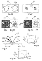
- “Folded document” means a document with or without a function of identifying a person or an object and that includes at least one folding zone, such as a passport booklet, a document with three foldable shutters in "triptych", as shown in figure 1a , such as a French driving license or a French driving license or a collapsible "accordion” document, as shown in the figure 1b or multi-tiered "portfolio" as represented in figure 1c .
- a pamphlet for example such as a passport booklet, usually has a cover and one or more inner sheets, for example at least sixteen sheets in the case of a passport booklet.
- these flap documents most often include at least one page of an inner sheet that includes security data, for example personal data. printed or engraved, and possibly a photograph relating to the bearer of the document with shutters. To further improve security, this data can be covered with a holographic protective film.
- the document can also include one or more well known security elements, such as a watermark or pseudo-watermark, a device integrated microcircuit, among others, these security elements may in particular be printed on one or more pages of the inner sheets and / or integrated therewith.
- WO 2007/034129 describes a document having a cover and an inner sheet having a secure data page.
- the data page comprises in particular a layer on which visible personal data relating to the document holder and another layer containing an electronic device in which all or some of these personal data are stored, the two layers being laminated between two other layers, plastic.
- plastic Such a document presents several disadvantages, in particular that it is almost impossible to customize the document after manufacture. Indeed, the presence of plastic layers makes it difficult to physically personalize the data page of the booklet with visible data prints after mounting the booklet. In addition, it also proves difficult to digitally personalize the document with a recording of all or part of personal data in the chip simultaneously with the physical personalization of the document by visible impressions of this data.
- Watermarks help to protect copying by optical means such as photocopying, photography or scanning.
- Watermarks can also be used for decorative purposes and prestige, especially for printing-writing papers, for example for letterheads or art papers such as watercolor papers.
- the watermarks are conventionally obtained during the manufacture of a wet-phase paper sheet by depositing the pulp on the embossed web of a round-shaped paper machine, the quantity of pulp deposited being higher in the hollow and lesser on the bumps compared to the rest of the paper.
- the watermarks can also be made by embossing a wet sheet with a watermarking roll (also called “dandy roll”) on a flat-bed paper machine.
- a watermarking roll also called "dandy roll”
- pseudo-watermarks reproduce the appearance of a watermark with differences in opacity.
- DE 3909351 discloses a film having a PVC layer with aluminum particles forming, when the film is illuminated by a laser, a negative image having the appearance of a watermark.
- These pseudo-watermarks can be obtained mechanically on the sheet by applying pressure with or without heat and / or chemically by applying a composition, for example by increasing the transparency of the paper locally by means of transparent substances.
- the density of fibrous material between the lightest and darkest areas of the pseudo-watermark may be uniform unlike a conventional watermark.
- RFID radiofrequency identification devices
- plastic identity cards comprising an RFID device, made from an assembly of polymeric layers.
- Such cards have little or no authentication security elements, including visual, if not sometimes surface embossing or holograms applied by transfer. In this way, it is relatively easy for a fraudster to reproduce the impressions, the personalizations or the visual security present on such cards from a blank plastic card.
- Security cards are still known comprising two polyethylene layers each comprising a pseudo-watermark produced by embossing hollow or raised, the two pseudo-watermarks combining during an observation in transmitted light.
- pane documents allowing their personalization before, during or after the production of documents, including physical customization, for example using print and / or another type of document. customization, or digital, for example using an integrated microcircuit device present in the document.
- the support may consist of the cover of the passport on which a fibrous sheet forming the cover page and the end page is intended to be glued.
- the structure may further comprise, in its thickness, an integrated microcircuit device, in particular contactless communication and / or contact.
- an integrated microcircuit device in particular contactless communication and / or contact.
- the integrated microcircuit device can be carried by the substructure.
- the invention it is possible to benefit from a security structure in a document with shutters offering the security associated with the presence of at least one watermark or pseudo-watermark, and possibly linked to the presence of a device integrated microcircuit.
- the presence of at least one fibrous layer may allow the physical personalization, particularly by printing, of the shutter document, whether before, during or after the manufacture of the shutter document, in particular the sealing or gluing of one or more fibrous layers with the substructure.
- the invention provides a new means for securing the shutter documents, thanks to the presence of a structure comprising a filigree fibrous layer such that the watermark is observable in light transmitted at the translucent region of the the face of the structure located on the side of the filigree fibrous layer.
- the displacement of the structure relative to the support may correspond to a rotation about the axis formed by the folding line of the flap document.
- the structure can be moved in a manner similar to an inner sheet of the flap document.
- the structure can correspond to an inner sheet of the flap document.
- the structure may correspond to an inner sheet having at least one data page on which personal data, for example in the form of impressions, and possibly a photograph of the holder of the document with flaps, may appear.
- the structure is not glued, laminated or fused, entirely to the support of the flap document.
- the structure preferably does not correspond to an inner sheet of the flap document comparable to a cover page or an end page of the document, glued to the support (or cover) of the flap document to allow its observation in transmitted light.
- the substructure may be bonded to the support, and in particular to the fibrous layer, only at the fold line, i.e. the substructure is movable in the same way as an inner sheet. .
- the substructure is rotatable about the axis formed by the fold line of the flap document.
- the substructure is arranged in the booklet of the inner sheets of the document with flaps being movable relative to the fibrous layer carrying the watermark or pseudo-watermark around the axis of the fold line.
- the substructure and the fibrous layer carrying the watermark or pseudo-watermark are adjacent in the booklet of the inner sheets, at least in the closed position of the passport.
- the structure in particular the substructure, may be connected to the support totally or partially, for example by at least part of an edge thereof, by a hinge, by a spiral binding, by a seam, by gluing, by sealing, melting, folding, stapling, among others.
- the structure, especially the substructure can be linked to the support at the fold line and / or an edge of the support, for example a lower or upper edge of the support.
- the structure can be folded relative to the support, in particular along a folding zone common to the folding zone of the support. At least a part of the structure can extend on one flap and overflow on a second flap along a strip parallel to the fold line, in particular at an edge, the strip making it possible to bond it to the support of the flap document .
- the structure and / or the strip may comprise, for example, perforations to enable the structure to be bonded to the support at the level of the fold line, for example by means of a spiral.
- Two inner sheets of the flap document may be formed from a single sheet folded on itself and connected along a fold line to form the two inner sheets.
- Two inner sheets of the flap document may be further formed from at least two different sheets folded and interconnected along their fold line to form the two inner sheets.
- the structure may comprise a watermark carried by the fibrous layer and at least partially superimposed on the translucent region of the substructure, such that the watermark is only observable in transmitted light through the structure at the level of the translucent region.
- the face of the structure located on the side of the fibrous layer, that is to say the face of the structure opposite to that in contact with the substructure.
- the structure may comprise a pseudo-watermark carried by the fibrous layer and at least partially superimposed on the translucent region of the substructure, so that the pseudo-watermark is observable in light transmitted through the structure at the level of the translucent region of the face of the structure located on the side of the fibrous layer, that is to say the face of the structure opposite to that in contact with the substructure.
- the structure may comprise two fibrous layers, the substructure comprising a translucent region being located between the fibrous layers, at least in the superposition position.
- these may each include a watermark or pseudo-watermark, which is observable in light transmitted through the structure, level of the translucent region of the substructure, than the face of the structure located on the side of the fibrous layer that carries it when the fibrous layers and the substructure are superimposed.
- the observations of the watermarks or pseudo-watermarks are made separately from respective different faces of the structure.
- the structure has a front face and a back face, comprises a first fibrous layer carrying at least a first watermark or pseudo-watermark and a second fibrous layer carrying at least a second watermark or pseudo-watermark, the first watermark or pseudo-watermark being observable in transmitted light, at least partially, than the front face of the structure and the second watermark or pseudo-watermark not being observable in transmitted light, at least partially , than the reverse side of the structure.
- the watermarks or pseudo-watermarks are preferably at least partially juxtaposed in the translucent region of the substructure.
- All or part of these watermarks or pseudo-watermarks may thus not be observable simultaneously in transmitted light on the same side of the structure at the translucent region of the substructure.
- the translucent region of the substructure can thus make it possible to prevent a combination of watermarks or pseudo-watermarks between them.
- the substructure may be bonded to two fibrous layers solely by the fold line so as to be arranged in the booklet of the inner sheets sandwiched between the two fibrous layers each carrying a watermark or pseudo-watermark.
- the substructure is disposed in the booklet of the inner sheets of the flap document being movable relative to each of the fibrous layers around the axis of the fold line. To proceed with the authentication of the document, it suffices then to hold the substructure and the fibrous layers together in a superimposed manner to find that the watermark or pseudo-watermark of a fibrous layer is observable in light transmitted through the structure, at the level of the translucent region of the substructure, than the face of the structure located on the side of this fibrous layer.
- watermark or pseudo-watermark a drawn image that appears in the thickness of the structure.
- the watermark or pseudo-watermark can be made in various ways known to those skilled in the art.
- the watermark may be a pattern engraved or pressed into a fibrous layer during its manufacture. Such a watermark can for example be seen by transparency by creating thinning or overloads of pasta at the time of manufacture of the fibrous layer on a paper machine with round shape with a relief or recessed impression in the training fabric of the round form. In this way, differences in opacity are created and the denser dough areas appear darker than the less dense areas which appear lighter compared to the rest of the leaf (called the vellum part), when the leaf is observed ( after drying) in transmitted light.
- the watermarks having different gray levels depending on the height of the embossings are called "multitone watermarks".
- the watermark can still come from areas where the fibrous layer has been pressed onto a flat-bed paper machine by means of a filigree roller which has the embossing of the embossed watermark, which has the effect of strongly pressing certain areas of the fibrous layer. and to remove the water contained in the fibers at the time of formation of the fibrous layer in the wet part.
- the pseudo-watermark may also be produced in the finished fibrous layer by mechanical and / or chemical means by application of certain products, this drawing being always visible in transparency.
- the pseudo-watermark may for example be produced by depositing or printing in certain zones of the fibrous layer a composition which modifies the transparency of the fibrous layer, in particular in order to produce light areas and dark areas, similar to those of a watermark, but without obtaining a result to obtain fineness and brightness variants comparable to those of a conventional watermark.
- the finished fibrous layer can be made transparent by applying, in particular areas, for example a generally oily composition which permanently crystallises the fibrous layer, for example a composition made of oil and transparent mineral material as described in the patent. US 2,021,141 or as for example a composition in the form of a wax combined with a solvent as described in U.S. Patent 1,479,337 .
- the finished fibrous layer can also be made transparent by locally applying a wax by heat transfer, as described in US Pat. US Patent 5,118,526 .
- the finished fibrous layer can be opacified, without, however, rendering it completely opaque, by applying, in certain zones, an opacifying agent which increases the opacity of the fibrous layer, as for example described in the patent application.
- an opacifying agent which increases the opacity of the fibrous layer, as for example described in the patent application.
- the opacifying agent may for example be an aqueous suspension of a pigment or a filler or a solution of a chemical compound, a colored compound or a dye.
- This agent can be applied during the manufacture of the fibrous layer, on the fibrous web, and before its removal from the fabric, so that the agent penetrates the interstices of the web and causes a change in the opacity of the web to be treated in selected areas, after drying.
- This manufacturing technique has the disadvantage of requiring special devices rollers to apply the agent, and preferably employing a suction device to penetrate the agent in the interstices of the web.
- International demand WO 1999/014433 also discloses another method of manufacturing a pseudo-watermark on a coated paper, which provides for imaging in the paper after the drying step following the last coating operation, performing the steps in which a rewetting solution on at least one side of the coated paper, in one or more determined areas, and applying pressure and heat to the area (s) of the rewetted coated paper of in order to evaporate the solution and to densify the coated paper in the zone or zones relative to the rest of the paper.
- the pseudo-watermark may finally be made mechanically by making marks by mechanical embossing of determined areas of the fibrous layer as described in the patent DE 3,718,452 .
- the two fibrous layers of the structure each comprise a watermark or pseudo-watermark
- the two watermarks or pseudo-watermarks may be different.
- watermarks or pseudo-watermarks can be complementary. They can be complementary in their visual effect or in relation to a concept or an image. For example, in the case of a structure of a flap document according to the invention, put as first watermark or pseudo-watermark on one side a national emblem and as a second watermark or pseudo-watermark on the other side. side, a text.
- a voucher one can put the logo of the issuing company and the value of the voucher respectively.
- the two watermarks or pseudo-watermarks are identical but placed symmetrically on each side of the translucent zone of the substructure.
- it may then be interesting to verify this visual identity between the watermarks or pseudo-watermarks when they are observed on each of the two faces of the structure for example a character always looking on the same side as this either by observation of the face located on the side of the first fibrous layer or the face located on the side of the second fibrous layer).
- the two watermarks or pseudo-watermarks are at least partially opposite one another.
- the integrated microcircuit device can be adapted to contactless communication technology, for example as described in the ISO 14443, ISO 15693 and ISO 18000 standards.
- the integrated microcircuit device can be adapted to contact communication technology, for example as described in ISO 7816.
- the structure may comprise an integrated microcircuit device with contact communication and an integrated microcircuit device without communication. contact, or an integrated microcircuit device for both a contact reading and a contactless reading.
- the integrated microcircuit device according to the invention may comprise in particular two electronic modules, one for the contact technology and the other for the contactless technology, for example for a hybrid smart card or an electronic double-sided contact module. contactless for dual chip card.
- the integrated microcircuit device may be able to communicate with an external reader.
- External reader means any device that makes it possible to communicate with the integrated microcircuit device, to activate it, to authenticate it, to read data contained therein, to receive such data and, where appropriate, to modify or even delete them partially or totally.
- the external drive can operate remotely or require contact.
- the integrated microcircuit device can result from the association of a chip with at least one antenna in the case of a non-contact system.
- a chip comprises for example a semiconductor base, generally a doped silicon wafer, sometimes made of a semiconductor polymer, and also generally comprises a memory, or even one or more microprocessors, for processing data. To function, it can receive the energy of a battery or a battery or be powered by a source of electrical energy brought by contact and / or without contact, that is to say in the latter case, to distance via a communication interface via an antenna.
- the chip is for example connected to the antenna in a non-contact power supply of inductive or capacitive type.
- Antenna chips are called "transponders" and generally use radiofrequency waves.
- the integrated microcircuit device may include a battery, also called “micro-battery”, integrated in its microcircuit or be connected to a micro-battery built into the structure.
- battery is meant a source of energy of electrochemical origin, rechargeable or not.
- the chip can still be powered by a photovoltaic system.
- the antenna of the integrated microcircuit device without contact can be of wired type, printed, in particular screen printing, etched, bonded, transferred, chemically deposited, made by electroplating, or carried by the integrated microcircuit device.
- the antenna of the integrated non-contact microcircuit device may be carried by a fibrous layer, by the substructure or by an adhesive layer, in particular an adhesive layer for assembling one or more fibrous layers and / or the substructure.
- the antenna may be located on one of the faces of the substructure or may be fully incorporated therein.
- the antenna can be made on the substructure before assembly with a fibrous layer.
- the antenna may be located between a fibrous layer and the substructure.
- the antenna can be carried by a face of a fibrous layer in contact with the substructure.
- the antenna can be made on the fibrous layer before assembly with the substructure.
- the integrated microcircuit device may be located on one of the faces of the substructure.
- the integrated microcircuit device is located outside the structure, in particular in a fibrous layer of the flap document, in particular in the cover of said document.
- the integrated microcircuit device may be incorporated at least partially into a fibrous layer.
- the integrated microcircuit device may be fully incorporated into the substructure.
- the integrated microcircuit device can be visible at least partially on one of the faces of the structure, especially when it is in contact.
- the integrated microcircuit device can be housed, at least partially, in the substructure, that is to say that all or part of the integrated microcircuit device is compensated in thickness by the substructure. This allows for example to protect the integrated microcircuit device, which is generally a fragile piece, while making access to it by possible forgers particularly difficult.
- the integrated microcircuit device can be further compensated at least partially in thickness by an adhesive layer of the substructure, serving to assemble it to one or more fibrous layers. The thickness of the substructure may exceed that of the integrated microcircuit device.
- the integrated microcircuit device is flush with at least one face of the substructure.
- the integrated microcircuit device can be flush with each of the faces of the substructure.
- the integrated microcircuit device may also include one or more of the electronic devices mentioned above.
- the electronic device or devices may be independent of the integrated microcircuit device, preferably being connected to the integrated microcircuit device by a wired, optical or radio link, for example by inductive coupling.
- the electronic device or devices can be supplied with electricity by a battery present on the integrated microcircuit device, in particular by a micro-battery on a chip.
- the electronic device or devices can still be powered by an external battery or battery, not present on the integrated microcircuit device, for example a flexible thin film battery that is distinct from a chip or by a photovoltaic cell, for example at least partially printed.
- an external battery or battery not present on the integrated microcircuit device, for example a flexible thin film battery that is distinct from a chip or by a photovoltaic cell, for example at least partially printed.
- the electronic device or devices can still be powered by capacitive or inductive coupling, for example during a communication between the integrated microcircuit device and an external reader.
- the electronic device (s), and possibly the associated supply device (s), for example one or more batteries, may be housed in the thickness of one of the layers of the structure, or alternatively may be produced by printing on one of the layers of the structure.
- the electronic device or devices are added to the structure as additional security means that may or may not interact with outside.
- the electronic device may be a switch that operates a light emitting device.
- the electronic device or devices may correspond to a detector.
- the detector may be configured to detect a change of at least one physicochemical magnitude.
- the detection can be performed outside the reading field of an external reader capable of obtaining at least one piece of information relating to said change from the integrated microcircuit device, and the integrated microcircuit device can be configured to signal to the external reader when communication with it, an attempt to damage the physical integrity of the structure following the detection of a corresponding change of said at least one physicochemical magnitude.
- the integrated microcircuit device is advantageously able to keep in memory the change or changes.
- phytochemical quantity is meant an intrinsic characteristic parameter or property of the structure or of an element present in or on the structure, the value of this parameter or of this property being modified during an intrusion or an physical violation of the structure.
- the electronic device or devices are incorporated in the structure for the purpose of adding a particular functionality, for example associated with the integrated microcircuit device or other electronic device.
- an electronic device may be a photovoltaic cell that recharges a battery used by a sensor.
- the integrated microcircuit device can still be integrated into the flap document holder.
- the substructure can for example correspond to an element of electromagnetic disturbance or "magnetic shield".
- An electromagnetic interference element may comprise means for attenuating, disturbing or blocking the electromagnetic coupling between an integrated microcircuit device, in particular without contact, and an external reader, of the magnetic material, conductive material or resonator circuit type.
- the substructure having the role of element of electromagnetic disturbance must however be able to present the properties sufficient to allow the observation the watermark or pseudo-watermarks that one of the faces of the structure, including sufficient properties in terms of transparency and light diffusion.
- the electromagnetic interference element prevents read access and / or in writing to the information recorded in the integrated microcircuit device, whether the reader is located in front of the first or second flap.
- the integrated microcircuit device can be integrated into the support of the flap document, and the substructure can correspond to an electromagnetic amplification element or "booster" electromagnetic.
- the electromagnetic amplification element can increase the communication distance between the integrated microcircuit device and an external reader.
- the structure in particular the substructure and / or the fibrous layer or layers of the structure, may comprise one or more security elements.
- security elements some are detectable with the naked eye, in daylight or in artificial light, without the use of a particular device.
- These security elements comprise for example colored fibers or boards, fully or partially printed or metallized wires. These security elements are called first level.
- security elements are detectable only with a relatively simple device, such as a lamp emitting in the ultraviolet or infrared.
- These security elements comprise, for example, fibers, boards, strips, wires or particles. These security elements may be visible to the naked eye or not, being for example luminescent under a lighting of a Wood lamp emitting in a wavelength of 365 nm. These security elements are said to be second level.
- security elements still require for their detection a more sophisticated detection device.
- These security elements are for example capable of generating a specific signal when they are subjected, simultaneously or not, to one or more external excitation sources. The automatic detection of the signal makes it possible to authenticate, if necessary, the document.
- These security elements comprise, for example, tracers in the form of active material, particles or fibers, capable of generating a specific signal when these tracers are subjected to optronic, electrical, magnetic or electromagnetic excitation. These security elements are said to be third level.
- the security elements present within the substructure and / or the fibrous layer or layers may have first, second or third level security features.
- One or more security elements as defined above may be present in the substructure and / or the fibrous layer (s) or in one or more security elements incorporated in the substructure and / or in the fibrous layer (s) , such as a wire, a fiber or a board.
- the structure may also comprise one or more so-called "tamper-proof" security elements, such as, for example, reagents for chemical products, for example capable of causing a color reaction in the presence of specific chemicals, for example chemicals used by the chemicals. fraudsters.
- security elements such as, for example, reagents for chemical products, for example capable of causing a color reaction in the presence of specific chemicals, for example chemicals used by the chemicals. fraudsters.
- the structure may comprise at least one fibrous layer which may carry a watermark or pseudo-watermark and, preferably, the structure comprises two fibrous layers each carrying a watermark or pseudo-watermark, as mentioned above.
- the fibrous layer may comprise one or more joined fibrous jets, in particular by laminating or by assembling the paper machine in the wet part during the manufacture of said fibrous layer.
- the two watermarks or pseudo-watermarks are at least partially superimposable in an observation configuration of the structure with the fibrous layers sandwiching the substructure in the translucent region, the two fibrous layers may advantageously not be combined visually at the of the translucent region of the substructure.
- the watermark or pseudo-watermark, at least partially superimposed on the translucent region of the substructure, of a fibrous layer may comprise a portion which is visually combined with a portion of the watermark or pseudo-watermark of the other fibrous layer. outside the translucent region of the substructure, and another portion that does not visually combine with any portion of the watermark or pseudo-watermark of the other fibrous layer at the translucent region of the substructure.
- the watermark or pseudo-watermark of each fibrous layer may be visible at least partially only on the face of the fibrous layer comprising it, especially at the level of the translucent region of the substructure.
- the watermark or pseudo-watermark of each fibrous layer may be visible at least partially on the face of the fibrous layer not comprising it, in particular outside the translucent region of the substructure.
- the two fibrous layers may each further comprise one or more watermarks or pseudo-watermarks, at least partially superimposed on the translucent region of the substructure, which visually combine with each other outside the translucent region of the substructure to form a pattern.
- the fibrous layers may be glued, laminated or fused to the substructure particularly at the level of the translucent region. Alternatively, the fibrous layers are simply connected to the substructure in a mobile manner along the axis of rotation of the fold line.
- the fibrous layer (s) may be made on a flat-bed or round-shaped paper machine, and the watermarks may be incorporated into the fibrous layer (s) in a moist part by conventional methods known to those skilled in the art.
- the fibrous layer or layers can still be produced on a flat-bed or round-shaped paper machine, and the pseudo-watermarks can be made on the finished layers by mechanical or chemical means according to conventional methods known to those skilled in the art. .
- At least one fibrous layer may comprise prints, including personalization, made, for example offset, by gravure, screen printing or flexography, intaglio, typography, laser or inkjet.
- the impressions may correspond to fixed mentions and / or variable mentions of an identity document. Impressions may include a photograph, for example that of the document holder.
- At least one fibrous layer may for example be based on LASERGUARD ® or JETGUARD ® type paper, sold by the company ARJOWIGGINS.
- At least one fibrous layer may be colored, fluorescent, iridescent or have any other shade or optical effect.
- At least one fibrous layer may be based on cellulosic fibers, for example cotton fibers, and / or synthetic fibers and / or natural organic fibers other than cellulosic fibers and / or mineral fibers.
- At least one fibrous layer may have a basis weight of between 60 and 230 g / m 2 , preferably between 70 and 90 g / m 2 .
- At least one fibrous layer may have a thickness of between 60 and 220 ⁇ m, preferably between 70 and 110 ⁇ m, for example about 100 ⁇ m.
- At least one fibrous layer comprises a recess, for example an opening in the form of a fiber-free reserve, made for example on a paper machine or out of a paper machine. for example by punch, by laser cutting or by water jet.
- the recess is preferably made in a portion of the fibrous layer that does not or does not overlap the translucent region of the substructure at the integrated microcircuit device.
- Two fibrous layers may each comprise such a recess, the recesses being for example facing one another.
- the structure may have a transparent window due to the transparency of the substructure. This window may constitute a security element or house one or more security elements, including optical, or facilitate their observation.
- one or more security elements may be located in the substructure, and be observable through the aforementioned window.
- This window can also be customized, for example to show a pattern or a printed element, engraved, embossed or perforated, relative to the wearer or the object to which it relates.
- a first impression can be made on the front face of the substructure
- a second impression can be made on the reverse side of the substructure and during the observation in transvision through the aforementioned window, a complementary pattern can appear by moiré effect between the first and second impressions.
- the recess or recesses present on at least one fibrous layer may each have an area of between 0.1 and 10 cm 2 .
- the recess or recesses may have any geometric shape, in particular rectangular or circular.
- At least one fibrous layer may comprise perforations, for example each having an area of between 0.2 and 7 mm 2 for a diameter of, for example, between 0.5 and 3 mm.
- perforations may be advantageous in that, when the structure is assembled, it makes it possible for an adhesive, belonging for example to the substructure, for example a transparent thermoplastic material, to diffuse through one or more layers. fibrous and thus to more effectively secure the entire structure.
- the perforations may form a pattern, such as an alpha numeric pattern and / or a pattern and / or symbol, to provide additional securing of the structure.
- At least one fibrous layer comprises an at least partially transparent patch or strip (e) and at least one fiber-free zone located opposite the patch or strip.
- the tape or patch may comprise a transparent plastic material, and may include one or more security elements such as holographic impressions or liquid crystals.
- Two fiber-free zones may each be located on a fibrous layer, facing one another, so as to form a through window to see through the strip or patch.
- At least one fibrous layer may comprise at least one so-called "anti-scratching" safety zone which provides protection against mechanical forgery.
- This zone comprises a set of regions of reduced thickness, so that any attempt to alter the surface of this fibrous layer leads to pierce the latter.
- Such a safety zone is described in the patent EP 1 252 389 .
- the substructure may comprise a translucent region or be translucent over its entire surface.
- the substructure may comprise a translucent region and / or diffusing light or be translucent and / or diffusing light over its entire surface.
- Translucent means that the substructure allows enough light to see through the structure.
- diffusing means that the substructure diffuses light because of its nature and its thickness. More particularly, depending on the refractive index of the substructure, it may have a diffusing power of light.
- the translucent region can extend from one edge to the other of the substructure.
- the translucent region may form any pattern and be of shape for example rectangular, triangular, square, circular, oval, polygonal, star, among others.
- the translucent region preferably has the same thickness as the substructure.
- the translucent region may for example occupy more than 50%, better 70% or 80%, even better 90%, of the volume corresponding to the substructure.
- the substructure can comprise several translucent regions, for example more than two, three or four translucent regions. These translucent regions may be arranged regularly or not on the substructure, for example with identical spacings between the regions, or randomly. These translucent regions may form a pattern, for example by being arranged close to each other.
- the substructure comprises two disjoint or juxtaposed translucent regions, the latter may be made differently, for example with different opacities, to create effects in transvision.
- the substructure may also include mineral or organic fillers, bubbles, cavitations conferring a diffusing character.
- the substructure may have a thickness of between 10 and 1000 ⁇ m, preferably between 50 and 1000 ⁇ m, preferably between 120 ⁇ m and 600 ⁇ m.
- the substructure may have one or more recesses as previously described for the fibrous layer or layers.
- the substructure may be monolayer or made of an assembly of two or more layers, for example of two, three or four layers, in particular fibrous and / or polymeric layers.
- the layers may consist of identical or different materials, for example such as those mentioned below for the substructure.
- the substructure may comprise one or more layers assembled using one or more adhesive layers, for example as defined below, or else without adhesive, by fusion or by welding.
- the substructure may be a transparent plastic film covered with a material having a high diffusing power, for example nanoparticles.
- the antenna associated with the integrated microcircuit device may be located between two constituent layers of the substructure, being for example glued on one side of one of the layers.
- the thickness and the nature of the layers of the substructure are advantageously chosen so that the substructure, in particular in the translucent region, has the desired properties of non-opacity and diffusion, so as to prevent a combination filigranes or pseudo-watermarks of the fibrous layers during a transmitted light observation of the structure.
- the substructure may comprise a layer of a thermoplastic material, for example polyethylene (PE), polyvinyl chloride (PVC), polyethylene terephthalate (PET), polycarbonate (PC), polyester carbonate (PEC), polyethylene terephthalate glycol (PETG) or acrylonitrile butadiene styrene (ABS), for example in the form of a film or an extruded layer.
- a thermoplastic material for example polyethylene (PE), polyvinyl chloride (PVC), polyethylene terephthalate (PET), polycarbonate (PC), polyester carbonate (PEC), polyethylene terephthalate glycol (PETG) or acrylonitrile butadiene styrene (ABS), for example in the form of a film or an extruded layer.
- PE polyethylene
- PVC polyvinyl chloride
- PET polyethylene terephthalate
- PC polycarbonate
- PEC polyester carbonate
- PETG polyethylene terephthalate glyco
- the substructure may also comprise or consist of a fibrous layer, especially a paper, for example a tracing paper.
- the substructure may be composite and comprise at least one polymer layer and a fibrous layer, each layer being for example chosen from the materials mentioned above.
- the substructure may be of PAPERLAM ® marketed by the company AROWIGGINS.
- the substructure may extend over the entire surface of the watermark (s) or pseudo-watermarks.
- the substructure may extend at a portion of the structure, preferably from one edge to the other of the structure, in an area facing the watermark or pseudo-watermarks, for example to form a band.
- the dimensions of the substructure can correspond to those of the cover of a passport for example, that is to say to both parts. Alternatively, they correspond to the dimensions of a single component.
- the substructure may extend only over a part of the surface of the watermark or watermark, a part of the watermark or pseudo-watermark being thus visible only from one face of the structure while the part not covered by the substructure is visible on both sides of the transmitted light structure.
- the substructure may also consist of a fibrous layer during the formation of which has been inserted a band constituting the translucent region, for example a transparent plastic film:
- Adhesive layer (s) Adhesive layer (s)
- the structure may comprise at least one adhesive layer, for example between a fibrous layer and the substructure.
- the structure may comprise two adhesive layers on either side of the substructure.
- the adhesive layers may be of a different nature.
- At least one adhesive layer may comprise a polyolefin, for example polyethylene.
- At least one adhesive layer may comprise an ethylene vinyl acetate.
- At least one adhesive layer may comprise a material as mentioned above for the substructure.
- At least one adhesive layer may comprise a crosslinking agent.
- This embodiment may, for example, make it possible to strengthen the adhesion between the different layers.
- the crosslinking agent of the adhesive layer may be crosslinkable under the action of radiation, especially ultraviolet radiation.
- the fibrous layer (s) can be assembled to the substructure in various ways, for example by means of one or more adhesive layers or without an adhesive layer, for example by fusion or welding.
- the adhesive layer or layers may be continuous, that is to say uniformly distributed over the entire surface of the fibrous layer (s) or substructure.
- the adhesive layer or layers may instead be discontinuous, in particular in a pattern and in particular they may be applied by gravure or screen printing.
- the fibrous layer or layers may therefore be bonded, in particular by bonding, partially or totally to the substructure.
- the adhesive layer or layers may be applied partially or totally to the fibrous layer or layers, or to the substructure.
- the substructure may present on at least one of its faces a polymer layer, for example a polycarbonate, which can allow its direct sealing under heat and pressure on the fibrous layer or layers.
- a polymer layer for example a polycarbonate
- the substructure may also present on at least one of its faces a polymer layer coated with an adhesive, for example a layer of polyethylene terephthalate coated with a layer of ethylene vinyl acetate, allowing its direct cold sealing or hot, with or without pressure on the fibrous layer or layers.
- a polymer layer coated with an adhesive for example a layer of polyethylene terephthalate coated with a layer of ethylene vinyl acetate, allowing its direct cold sealing or hot, with or without pressure on the fibrous layer or layers.
- the fibrous layer or layers may have on their faces facing the substructure, a surface coating allowing their direct sealing hot and under pressure on the substructure.
- the fibrous layer or layers may comprise a paper substrate impregnated with heat-sealing latex.
- the fibrous layer or layers may have on their faces opposite the substructure, an adhesive layer allowing their direct sealing cold or hot, with or without pressure, on the substructure.
- the adhesive layer or layers present on the fibrous layer or layers may correspond to liquid adhesives previously cold-coated or hot-coated on the face or faces of the fibrous layer or layers facing the substructure.
- one or more adhesive layers are used to assemble the fibrous layer (s) with the substructure.
- the adhesive layer or layers may for example correspond to one or more pressure-sensitive or thermoplastic films.
- the substructure may also comprise one or more openings or perforations, preferably not superimposed on the electronic device and / or on any antenna, in order to allow the adhesive layer (s) used to assemble the fibrous layer or layers with the sub-structure. structure, to mix and thus ensure better fixation of the substructure with the fibrous layer or layers.
- At least one adhesive layer may comprise one or more security elements as described above.
- the assembly of the substructure with the fibrous layer or layers may take place before, during or after the attachment of the structure to the support of the shutter document.
- At least one fibrous layer and / or the substructure can be customized, in particular using impressions and / or data recorded in an integrated microcircuit device, before, during or after the fixation of the structure to the support of the document with shutters.
- any customizations of the fibrous layer (s) may be protected, in particular by a transparent transparent film or not.
- Said film may be a thick film based on PET or PE, in particular to allow hot lamination on the fibrous layer, or an adhesive film.
- Such films are in particular marketed by Fasver or Hologramm Industries.
- the substructure can also be inserted between the two fibrous layers on a paper machine during the formation of the fibrous layers.
- the structure according to the invention may have a final thickness of between 100 and 1000 ⁇ m, preferably between 150 and 500 ⁇ m.
- the structure can have a constant thickness.
- the structure may have a variable thickness, especially higher in the central part than on the edges of the structure.
- the document can be an identity document, including an identity card or, preferably a passport, a means of payment, including a voucher or a voucher, a ticket to access cultural events or sports, a certificate of authenticity.
- the inner sheet can be folded and bound to the flap document holder, for example a passport cover, at the fold line.
- the inner sheet may define two inner pages on either side of the folding line of the document with shutters, each inner page defining a fibrous layer carrying at least one watermark or pseudo-watermark, so that by folding the sheet Inside the fold line watermarks or pseudo-watermarks are superimposed at least partially.
- the pane document may also comprise at least two distinct inner sheets, each inner sheet defining a fibrous layer carrying at least one watermark or pseudo-watermark, the two watermarks or pseudo-watermarks being located on the same side of the fold line so that they overlap at least partially.
- the pane document may further comprise a first inner sheet and a second inner sheet, each inner sheet defining two inner pages on either side of the fold line and each inner page defining a fibrous layer having at least one watermark or pseudo watermark, such that the watermarks or pseudo-watermarks of the first and second inner layers located on the same side of the fold line overlap at least partially.
- the translucent region of the substructure may be superimposed on the fibrous layer in a configuration such that it completely or partially covers the watermark or pseudo-watermark.
- the translucent region of the substructure can be superimposed on the two watermarks or pseudo-watermarks, being placed between the inner sheets.
- the substructure can have variable dimensions.
- the substructure may have a width equal to the width of a page of the inner sheet, that is to say a width equal to the distance between the fold line and the edge of the flap document.
- the substructure may still have a width less than the width of a page of the inner sheet.
- the substructure may have a width greater than the width of a page of the inner sheet.
- the width of the substructure is less than the width of a page of the inner sheet, this may allow to leave free an assembly area of the fibrous layers together in the case of two inner sheets.
- the substructure may still have a width less than, equal to or greater than the width of a page of the inner sheet, the substructure being bonded, in particular by gluing, sealing or sewing, to the support of the flap document at the level of the fold line.
- the shutter document may comprise one or more fibrous and / or thermoplastic inner sheets.
- the flap document may for example comprise at least two thermoplastic sheets associated or not with a heat-sealing adhesive layer, between which is placed the structure according to the invention.
- the structure may or may not include one or more adhesive layers to facilitate its assembly with the thermoplastic inner sheets.
- the structure 1 comprises two fibrous layers 2a and 2b between which is located a substructure 3 formed of an intermediate polymer layer on which is placed a non-contact integrated microcircuit device 4 and an antenna 5.
- the substructure 3 is in this completely translucent example.
- the structure 1 further comprises an adhesive layer 7a placed between the substructure 3 and the fibrous layer 2a, and another adhesive layer 7b placed between the substructure 3 and the fibrous layer 2b.
- the structure 1 has a greater thickness in the central part, due to the thickness of the assembly formed by the different superimposed layers, than at the edges of the structure 1.
- the adhesive layers 7a and 7b are in this example in the form of thermoplastic polyethylene films, hot-rolled.
- the polyethylene layer 7a allows partial or total compensation of the integrated microcircuit device 4, the layer of fluent thermoplastic polyethylene on either side of the integrated microcircuit device 4 during lamination.
- Substructure 3 is in this example monolayer and is in the form of a transparent polyethylene terephthalate film at least 100 microns thick.
- Substructure 3 relates to one of its faces the integrated microcircuit device 4 which can be in the form of a chip marketed by PHILIPS under the reference MIFARE ® .
- the integrated microcircuit device 4 is connected to an antenna 5, for example a copper antenna engraved on one of the faces of the substructure 3.
- the two fibrous layers 2a and 2b have for example a basis weight equal to 90 g / m 2 .
- the fibrous layer 2a comprises a watermark or pseudo-watermark 8a, for example in the form of a checkerboard as illustrated, and the fibrous layer 2b has a watermark or pseudo-watermark 8b, for example in the form of the combination of a cardioid and a nephroid.
- Each of the watermarks or pseudo-watermarks 8a and 8b is visible only on one side of the structure 1.
- the watermark or pseudo-watermark 8a is visible only on the recto side of the structure 1 where the layer appears. fibrous 2a
- the watermark or pseudo-watermark 8b is visible only on the back side of the structure 1 where the fibrous layer 2b.
- the figure 3 represents, in front view, the front face of the structure 1 of the figure 1 .
- the figure 4 represents, in front view, the reverse side of the structure 1 of the figure 1 .
- the structure 1 comprises two fibrous layers 2a and 2b, for example identical to those of the example of FIG. figure 1 .
- the structure 1 further comprises a substructure 3 comprising a translucent fibrous interlayer layer, on one of the faces of which is a non-contact integrated microcircuit device 4 and an antenna 5.
- the substructure 3 is advantageously entirely translucent.
- Substructure 3 is for example tracing paper and has for example a grammage equal to 65 g / m 2 .
- the integrated circuit device 4 is for example a chip of the "flip chip” type connected to an antenna 5, for example based on silver and silk-screen printed.
- Each of the fibrous layers 2a and 2b further comprises respectively an adhesive layer 7a and 7b, for example in the form of a pressure-sensitive adhesive, previously coated at 25 g / m 2, for example, on the inner faces of the fibrous layers 2a and 2b.
- an adhesive layer 7a and 7b for example in the form of a pressure-sensitive adhesive, previously coated at 25 g / m 2, for example, on the inner faces of the fibrous layers 2a and 2b.
- the figure 6 represents another example of structure 1 according to the invention.
- the structure 1 comprises two fibrous layers 2a and 2b, for example identical to that of the example of the figure 1 .
- the two fibrous layers 2a and 2b are coated on their inside with two adhesive layers 7a and 7b allowing their subsequent sealing on the substructure 3.
- the structure 1 further comprises a substructure 3 consisting of three intermediate layers 3a, 3b and 3c.
- Substructure 3 is in this example entirely translucent.
- the layer 3a is for example a transparent polyethylene terephthalate film on one of the faces of which is disposed the integrated microcircuit device 4 and the antenna 5.
- the integrated microcircuit device 4 is for example a chip marketed by PHILIPS under the reference MIFARE ® , connected to the antenna 5 which is for example an engraved copper antenna.
- the layer 3b is for example a transparent polyethylene terephthalate film on which is coated layer 3c, which is for example a layer of polyethylene and ethylene vinyl acetate transparent thermoplastic.
- the layer 3c has a thickness greater than or equal to that of the integrated microcircuit device 4, so as to compensate for the thickness of this device.
- the figure 7 represents another example of structure 1 according to the invention.
- the structure 1 comprises two fibrous layers 2a and 2b, having for example a grammage of 65 g / m 2 and a thickness equal to 70 microns.
- the structure 1 further comprises a substructure 3 that may consist of several transparent layers of polyethylene terephthalate and ethylene vinyl acetate (not shown), some of which have at least one recess for incorporating an integrated microcircuit device 4 under form of a module chip connected to an antenna 5.
- the substructure 3 is advantageously entirely translucent.
- Two adhesive layers 7a and 7b are also present on either side of the substructure 3 so as to ensure cohesion with the fibrous layers 2a and 2b.
- the adhesive layers 7a and 7b are, for example, heat sealing layers made of ethylene vinyl acetate allowing the direct lamination of the substructure 3 between the two fibrous layers 2a and 2b.
- the figure 8 represents another example of structure 1 according to the invention.
- the structure 1 comprises two fibrous layers 2a and 2b, for example identical to the fibrous layers 2a and 2b of the example of the figure 7 .
- the fibrous layers 2a and 2b of the structure 1 are pre-coated respectively on their inner face with adhesive layers 7a and 7b, heat-activatable and thermosetting, applied in the form of liquid adhesives based on polyurethane mixed with a blocked isocyanate.
- the structure 1 further comprises a substructure 3 having for example a thickness of 260 microns.
- the substructure is here for example entirely translucent.
- Substructure 3 comprises a layer 3a of paper, for example of thickness equal to 130 ⁇ m, comprising on one of its faces a copper wire antenna 5 fixed for example by ultrasound, and a recess in which is housed partially integrated microcircuit device 4 without contact.
- the substructure 3 also comprises a paper layer 3b, having for example a thickness equal to 130 ⁇ m, also comprising a recess facing the recess of the layer 3a, in which the integrated microcircuit device is housed at least partially. 4.
- the integrated microcircuit device 4 is for example a module chip of the MOB 6 type, marketed by the company PHILIPS.
- the fibrous layers 2a and 2b of the structure 1 comprise one or more watermarks or pseudo-watermarks, for example those described in the example of the figure 2 .
- the figure 9 represents another example of structure 1 according to the invention.
- the structure 1 comprises two fibrous layers 2a and 2b respectively coated on their inner face with two adhesive layers 7a and 7b.
- the fibrous layer 2a has several identical watermarks 50, as can be seen in FIG. figure 10 , representing the front face of structure 1 of the figure 9 .
- the fibrous layer 2b also has several identical watermarks 60, as can be seen in FIG. figure 11 , representing the reverse side of structure 1 of the figure 9 .
- the substructure 3 advantageously has dimensions, in particular a width, smaller than those of the fibrous layers 2a and 2b.
- the substructure 3 extends from one edge to the other of the structure 1, in the width direction, as can be seen on the Figures 10 and 11 .
- An integrated microcircuit device 4 in the form of an AOB ("Antenna On Board”) chip with an on-board antenna is incorporated in the substructure 3.
- At least a part, better all, of a watermark 50 of the fibrous layer 2a and at least a portion, better all, of a watermark 60 of the fibrous layer 2b are superimposed on the substructure 3.
- the watermarks 50 and 60 of the fibrous layers 2a and 2b which are not superimposed on the substructure 3, are visible both on the front side and on the back side of the structure 1, as can be seen on the Figures 10 and 11 .
- these watermarks 50 and 60 can combine with each other so as to form a pattern resulting from their combination, representing in this example a butterfly enclosed in the net.
- the combination between watermarks of the fibrous layers 2a and 2b may be possible for example only outside the substructure 3.
- the structure 1 comprises two fibrous layers 2a and 2b and two adhesive layers 7a and 7b identical to those of the structure 1 of the figure 9 .
- the structure 1 comprises a substructure 3 extending from one edge to the other of the structure 1, in the direction of the length and the width.
- the substructure 3 comprises a translucent region 15, obtained for example by the juxtaposition of several translucent regions 16 forming between them a pattern, for example in the form of a star.
- the fibrous layers 2a and 2b may comprise one or more watermarks or pseudo-watermarks, for example such as those described above, preferably superimposed at least partially on the translucent region of the substructure 3.
- each part of a watermark or pseudo-watermark located at the level of the translucent region 15 is visible only on the side of the structure 1 which shows the fibrous layer which carries it.
- the watermark or pseudo-watermarks of the fibrous layer 2a can for example be combined with the watermark or pseudo-watermarks of the fibrous layer 2b.
- the figure 13 represents in front view the substructure 3 of the figure 12 , on which one can see the pattern formed by the translucent region 15.
- the integrated microcircuit device (s) 4 may comprise or be associated with one or more electronic devices in the form of detectors configured to detect a change of at least one physicochemical quantity, notably a physicochemical quantity. characteristic of a layer comprising the integrated microcircuit device concerned, for example the substructure 3. In this way, it may be possible to report any attempt to damage the physical integrity of the structure following the detection of a change in physicochemical magnitude.
- the figure 14 represents a flap document 100 comprising a support 101 defining two flaps 101a and 101b connected by a fold line 102.
- the flap document 100 includes in this example an inner sheet 103 which has two inner pages 103a and 103b on either side of the fold line 102.
- the inner page 103a carries a first watermark or pseudo-watermark 110a
- the inner page 103b carries a second watermark or pseudo-watermark 110b.
- two watermarks or pseudo-watermarks 110a and 110b are carried by one and the same inner sheet 103.
- the method of manufacturing the flap document 100 according to the invention comprises, in particular, the step consisting in superimposing at least partially on a substructure (not shown in FIG. figure 14 ) to the watermarks or pseudo-watermarks 110a and 110b by placing the substructure between the inner pages 103a and 103b of the inner sheet 103.
- the flap document 100 has two inner sheets 103 and 104 interconnected at the fold line 102.
- Each inner sheet 103 and 104 has an inner page 103a and 104a, each carrying a watermark or pseudo-watermark 110a and 110b, the two inner pages 103a and 104a on the same side of the fold line 102. In this way, the watermarks or pseudo-watermarks 110a and 110b overlap at least partially. Thus, the watermarks or pseudo-watermarks 110a and 110b are carried by two inner sheets 103 and 104 of the flap document 100 distinct.
- the method of manufacturing the flap document 100 according to the invention then comprises the step of superimposing a substructure (not represented on the figure 15 ) to the watermarks or pseudo-watermarks 110a and 110b, placing the substructure between the inner pages 103a and 104a of the inner sheets 103 and 104.
- FIG. 16 to 17 various examples of positioning a substructure 120 between the watermarks or pseudo-watermarks 110a and 110b. These positioning examples are illustrated with a flap document configuration 100 similar to that shown in FIG. figure 15 but are also applicable to the configuration shown in the figure 14 .
- the substructure 120 has a width less than the width of the inner pages 103a and 104a so that the flap document 100 has areas on either side of the substructure 120 which may possibly allow the layers to be assembled. fibrous constituted by the inner pages 103a and 104a therebetween.
- the substructure 120 may be linked to the fibrous layers constituted by the inner pages 103a and 104a, or alternatively, be free, that is to say, not bonded to the support 101 and the fibrous layers constituted by the inner pages 103a and 104a.
- the substructure 120 has a width greater than the widths of the inner pages 103a and 104a, and is positioned between the inner pages 103a and 104a so that the outer end of the substructure 120 is exactly superimposed on the outer ends of the inner pages 103a and 104a, and that the inner end of the substructure 120, i.e. the end lying at the fold line 102, is attached to the support 101 at the line folding 102, for example by gluing or sewing.
- the substructure is also fixed by its inner end to the support 101, just as for the example of the figure 17 .
- the outer end of the substructure 120 is not superimposed on the outer ends of the inner pages 103a and 104a. In this way, it is for example possible to assemble the fibrous layers formed by the inner pages 103a and 104a together.
- the flap document 100 has two inner sheets 103 and 104.
- the inner sheet 103 has an inner page 103a having a first watermark or pseudo-watermark 110a and an inner page 103b carrying a second watermark or pseudo-watermark 110c. It is the same for the inner sheet 104 which has an inner page 104a carrying a first watermark or pseudo-watermark 110b and an inner page 104b which carries a second watermark or pseudo-watermark 110d.
- the watermarks or pseudo-watermarks 110a to 110d are formed on the inner pages 103a, 103b, 104a and 104b so that the watermarks or pseudo-watermarks 110a and 110b, respectively the watermarks or pseudo-watermarks 110c and 110d, are superimposed on the less partially.
- the flap document 100 further comprises a substructure 120, constituted by an assembly of two distinct substructures or constituted by a single folded substructure at the fold line 102.
- the substructure 120 is placed enter the inner sheets 103 and 104, so as to overlap at least partially with both the watermarks or pseudo-watermarks 110a and 110b, and the watermarks or pseudo-watermarks 110c and 110d.
- the inner sheet 104 may for example be assembled first to the support 101, then the substructure 120 may be assembled in turn to the support 101 at the fold line 102, and finally the inner sheet 103 can be assembled last to the support 101 at the fold line 102.
- the substructure 120 has a width less than the width of the inner sheets 103 and 104 and the width of the support 101 so that the flap document 100 has areas at the edges of the inner sheets 103 and 104 which allow, if necessary, to assemble the fibrous layers formed by the inner pages 103a, 103b, 104a and 104b therebetween.
- the structure 200 is such that it comprises two fibrous layers (not shown) respectively carrying watermarks 200a and 200b respectively.
- the structure 200 further comprises a substructure (not shown) which is totally superimposed on the watermarks 200a and 200b.
- the figure 20 represents the front side of the structure 200 on which it is found that only observed light transmitted watermarks 200a carried by the fibrous layer on the front of the structure 200.
- the figure 21 represents the back side of the structure 200 on which it is found that one can observe in transmitted light only the watermarks 200b carried by the fibrous layer on the back side of the structure 200.
- the substructure 210 represented by a dark zone in the figures, is superimposed on only a part of the watermarks 200a and 200b so that in the part of the structure 200 devoid of the substructure 210, the watermarks 200a and 200b are superimposed on each other by observation in transmitted light.
- the flap document 100 comprises a support 101 defining two flaps 101a and 101b connected by a fold line 102.
- the flaped document 100 has one or more inner sheets 103 and 104, which may be as previously described, for example fibrous and / or polymeric, and two inner sheets 106 each having a single thermoplastic layer or a layer-associated thermoplastic layer. heat sealing adhesive.
- a structure 1 comprising a substructure 120 and a fibrous layer 2a which has a watermark or pseudo-watermark 8a.
- the structure 1 may or may not include one or more adhesive layers to facilitate assembly with the inner sheets 106.
- the structure 1 is assembled, in particular fixed, between the thermoplastic inner sheets 106 during the sealing of the inner sheets 106 together.
- two sheets 103 and 104 are joined by sealing along a strip 105 to form two inner sheets for a flap document according to the figure 24 of the invention.
- two sheets 103 and 104 are folded and interconnected at a fold line 102 by one of the methods described above to form two inner sheets for a flap document according to the figure 24 of the invention.
- the inner sheets thus formed can be connected to the fold line of the cover of a shutter document according to the invention.
- the flap document is for example made in a manner similar to the flap document 100 described in figure 19 .
- the substructure 120 extends partially by one of its ends between two portions of the inner sheets 103 and 104 devoid of watermark or pseudo-watermark.
- FIGS. 28 to 30 illustrate the possibility for the pane document to have a configuration as described with reference to Figures 1a to 1c .
- the structure is assembled by the end of a portion of the fibrous layer 103 at one end of the support 101.
- the document can have a configuration similar to that of the figure 1a .
- the Figures 29 and 30 represent, respectively before and after assembly of the structure, another possibility of producing a flap document 100 according to the invention.
- the ends of the fibrous layers carrying the watermarks or pseudo-watermarks 10a and 110b are connected to two different ends of the support 101, so that the structure is located between two parts of the support 101.
- the flap document then has a once the structure assembled a configuration similar to that of the figure 1a , the central flap being constituted by the structure.
- the substructure may be bonded to the support and / or the fibrous layer or layers of the structure, or alternatively may be free, that is to say linked to the support and / or the layer (s). fibrous structure only by the folding zone.
- the substructure is movable with respect to the fibrous layers along an axis of rotation corresponding to the fold line.
- the authentication of the pane document can for example be done voluntarily by holding together the substructure and the fibrous layer in a superimposed manner to find that the watermark or pseudo-watermark is observable in light transmitted through the structure, at the level of the translucent region of the substructure, than of the face of the structure situated on the side of the fibrous layer.
- the substructure may for example be inserted between the fibrous layers.
Description
La présente invention se rapporte au domaine des documents de sécurité. Elle concerne un document à volets comportant une structure munie d'un filigrane ou pseudo-filigrane, et le procédé de fabrication d'un tel document.The present invention relates to the field of security documents. It relates to a flap document comprising a structure provided with a watermark or pseudo-watermark, and the method of manufacturing such a document.
Par « document à volets », on entend un document présentant ou non une fonction d'identification d'une personne ou d'un objet et qui comporte au moins une zone de pliage, telle qu'un livret de passeport, un document à trois volets pliable en « triptyque », tel que représenté à la
Un document à volets, par exemple tel qu'un livret de passeport, comporte généralement une couverture et une ou plusieurs feuilles intérieures, par exemple au moins seize feuilles dans le cas d'un livret de passeport.A pamphlet, for example such as a passport booklet, usually has a cover and one or more inner sheets, for example at least sixteen sheets in the case of a passport booklet.
Pour permettre de sécuriser de tels documents à volets, notamment contre les tentatives de falsifications et/ou de contrefaçons, ceux-ci comportent le plus souvent au moins une page d'une feuille intérieure qui comporte des données de sécurité, par exemple des données personnelles imprimées ou gravées, et éventuellement une photographie relative au porteur du document à volets. Pour améliorer davantage la sécurisation, ces données peuvent être recouvertes d'un film de protection holographique. En outre, pour permettre l'authentification d'un tel document et rendre plus difficile une tentative de contrefaçon, le document à volets peut encore comporter un ou plusieurs éléments de sécurité bien connus, tel qu'un filigrane ou pseudo-filigrane, un dispositif à microcircuit intégré, entre autres, ces éléments de sécurité pouvant notamment être imprimés sur une ou plusieurs pages des feuilles intérieures et/ou intégrés à celles-ci.To make it possible to secure such flap documents, especially against falsification and / or counterfeit attempts, these most often include at least one page of an inner sheet that includes security data, for example personal data. printed or engraved, and possibly a photograph relating to the bearer of the document with shutters. To further improve security, this data can be covered with a holographic protective film. In addition, to enable the authentication of such a document and make it more difficult to counterfeit, the document can also include one or more well known security elements, such as a watermark or pseudo-watermark, a device integrated microcircuit, among others, these security elements may in particular be printed on one or more pages of the inner sheets and / or integrated therewith.
La demande internationale
Par ailleurs, il est connu d'utiliser comme moyen de sécurité dans les documents de sécurité des filigranes qui permettent d'authentifier un document par observation en lumière transmise.Furthermore, it is known to use as a security means in the security documents watermarks that authenticate a document by observation transmitted light.
Les filigranes permettent de protéger de la copie par des moyens optiques tels que la photocopie, la photographie ou la numérisation.Watermarks help to protect copying by optical means such as photocopying, photography or scanning.
Les filigranes peuvent également être utilisés à des fins décoratives et de prestige, notamment pour les papiers impression-écriture, par exemple pour les têtes de lettres ou des papiers d'art comme les papiers pour aquarelle.Watermarks can also be used for decorative purposes and prestige, especially for printing-writing papers, for example for letterheads or art papers such as watercolor papers.
Les filigranes sont classiquement obtenus lors de la fabrication d'une feuille de papier en phase humide par le dépôt de la pâte à papier sur la toile embossée d'une machine à papier à forme ronde, la quantité de pâte déposée étant plus élevée dans les creux et moindre sur les bosses par rapport au reste du papier.The watermarks are conventionally obtained during the manufacture of a wet-phase paper sheet by depositing the pulp on the embossed web of a round-shaped paper machine, the quantity of pulp deposited being higher in the hollow and lesser on the bumps compared to the rest of the paper.
Les filigranes peuvent aussi être réalisés par embossage d'une feuille humide par un rouleau filigraneur (appelé aussi « dandy roll ») sur une machine à papier à table plate.The watermarks can also be made by embossing a wet sheet with a watermarking roll (also called "dandy roll") on a flat-bed paper machine.
Il est aussi connu de réaliser des pseudo-filigranes sur une feuille de papier. Les pseudo-filigranes reproduisent l'apparence d'un filigrane en présentant des différences d'opacité.
En outre, afin d'augmenter le niveau de sécurisation des documents de sécurité et de rendre leur falsification plus difficile, il est également connu d'y incorporer des dispositifs à microcircuit intégré, notamment RFID (dispositifs d'identification radiofréquence). Ces dispositifs, sous forme par exemple de puce associée à une antenne, permettent de stocker et éventuellement de modifier des informations propres au porteur ou à l'objet auquel ils se rapportent, au type de document émis ou à l'historique des évènements.In addition, in order to increase the security level of security documents and make their falsification more difficult, it is also known to incorporate integrated microcircuit devices, especially RFID (radiofrequency identification devices). These devices, for example in the form of a chip associated with an antenna, make it possible to store and possibly modify information specific to the wearer or the object to which they relate, to the type of document issued or to the history of the events.
On connaît par exemple des cartes d'identité en plastique comportant un dispositif RFID, réalisées à partir d'un assemblage de couches polymériques. De telles cartes ne comportent que peu ou pas d'éléments de sécurité d'authentification, notamment visuelle, si ce n'est parfois des embossages de surface ou des hologrammes appliqués par transfert. De la sorte, il est relativement aisé pour un fraudeur de reproduire les impressions, les personnalisations ou les sécurités visuelles présentes sur de telles cartes à partir d'une carte vierge en plastique.For example, plastic identity cards comprising an RFID device, made from an assembly of polymeric layers, are known. Such cards have little or no authentication security elements, including visual, if not sometimes surface embossing or holograms applied by transfer. In this way, it is relatively easy for a fraudster to reproduce the impressions, the personalizations or the visual security present on such cards from a blank plastic card.
On connaît encore des cartes de sécurité comportant deux couches de polyéthylène comportant chacune un pseudo-filigrane réalisé par embossage en creux ou en relief, les deux pseudo-filigranes se combinant lors d'une observation en lumière transmise.Security cards are still known comprising two polyethylene layers each comprising a pseudo-watermark produced by embossing hollow or raised, the two pseudo-watermarks combining during an observation in transmitted light.
Il existe un besoin pour renforcer encore la sécurité des documents de sécurité.There is a need to further enhance the security of security documents.
Il existe notamment un besoin pour proposer de nouvelles sécurités aux documents à volets contre les falsifications ou contrefaçons, qui soient facilement observables tout en présentant un niveau de sécurisation suffisant, plus difficiles à contrefaire et à détourner.In particular, there is a need to provide new security for documents against falsification or counterfeit, which are easily observable while having a sufficient level of security, more difficult to counterfeit and to divert.
Il existe encore un besoin pour proposer une nouvelle sécurité aux documents à volets permettant leur personnalisation avant, pendant ou après la fabrication des documents, notamment une personnalisation physique, par exemple à l'aide d'impressions et/ou d'un autre type de personnalisation, ou numérique, par exemple à l'aide d'un dispositif à microcircuit intégré présent dans le document.There is still a need to provide a new security for the pane documents allowing their personalization before, during or after the production of documents, including physical customization, for example using print and / or another type of document. customization, or digital, for example using an integrated microcircuit device present in the document.
L'invention a ainsi pour objet, selon l'un de ses aspects, un document à volets comportant :
- un support définissant au moins deux volets reliés par au moins une ligne de pliage,
- une structure liée au support, notamment au niveau de la ligne de pliage, avec une possibilité de déplacement relativement à celui-ci et s'étendant au moins partiellement entre les deux volets lorsque le document à volets est plié, la structure comportant :
- une couche fibreuse,
- une sous-structure comportant une région translucide,
- un filigrane ou pseudo-filigrane porté par la couche fibreuse et se superposant au moins partiellement à la région translucide de la sous-structure, de telle sorte que le filigrane ou pseudo-filigrane ne soit observable en lumière transmise à travers la structure, au niveau de la région translucide de la sous-structure, que de la face de la structure située du côté de la couche fibreuse, c'est-à-dire la face adjacente à la couche fibreuse.
- a support defining at least two flaps connected by at least one fold line,
- a structure related to the support, in particular at the level of the fold line, with a possibility of movement relative to it and extending at least partially between the two flaps when the flap document is folded, the structure comprising:
- a fibrous layer,
- a substructure comprising a translucent region,
- a watermark or pseudo-watermark carried by the fibrous layer and at least partially superimposed on the translucent region of the substructure, such that the watermark or pseudo-watermark is observable in light transmitted through the structure, at the level of of the translucent region of the substructure, that of the face of the structure located on the side of the fibrous layer, that is to say the face adjacent to the fibrous layer.
Par exemple, dans le cas d'un document tel qu'un passeport, le support peut consister en la couverture du passeport sur laquelle une feuille fibreuse formant la page de garde et la page de fin est destinée à être collée.For example, in the case of a document such as a passport, the support may consist of the cover of the passport on which a fibrous sheet forming the cover page and the end page is intended to be glued.
La structure peut encore comporter, dans son épaisseur, un dispositif à microcircuit intégré, notamment à communication sans contact et/ou avec contact. En particulier, le dispositif à microcircuit intégré peut être porté par la sous-structure.The structure may further comprise, in its thickness, an integrated microcircuit device, in particular contactless communication and / or contact. In particular, the integrated microcircuit device can be carried by the substructure.
Grâce à l'invention, il est possible de bénéficier d'une structure de sécurité dans un document à volets offrant la sécurité liée à la présence d'au moins un filigrane ou pseudo-filigrane, et éventuellement liée à la présence d'un dispositif à microcircuit intégré. De plus, la présence d'au moins une couche fibreuse peut permettre la personnalisation physique, notamment par impression, du document à volets, que ce soit avant, pendant ou après la fabrication du document à volets, notamment le scellage ou le collage d'une ou de plusieurs couches fibreuses avec la sous-structure.Thanks to the invention, it is possible to benefit from a security structure in a document with shutters offering the security associated with the presence of at least one watermark or pseudo-watermark, and possibly linked to the presence of a device integrated microcircuit. In addition, the presence of at least one fibrous layer may allow the physical personalization, particularly by printing, of the shutter document, whether before, during or after the manufacture of the shutter document, in particular the sealing or gluing of one or more fibrous layers with the substructure.
Par ailleurs, dans un document à livrets traditionnel, on peut trouver des feuilles intérieures comportant une couche fibreuse filigranée et telle que le filigrane soit observable en lumière transmise de chaque côté de la couche fibreuse. Avantageusement, l'invention apporte quant à elle un nouveau moyen de sécurisation des documents à volets, grâce à la présence d'une structure comportant une couche fibreuse filigranée telle que le filigrane ne soit observable en lumière transmise au niveau de la région translucide que de la face de la structure située du côté de la couche fibreuse filigranée.Furthermore, in a traditional booklet document, there can be found inner sheets having a filigree fibrous layer and such that the watermark is observable in transmitted light on each side of the fibrous layer. Advantageously, the invention provides a new means for securing the shutter documents, thanks to the presence of a structure comprising a filigree fibrous layer such that the watermark is observable in light transmitted at the translucent region of the the face of the structure located on the side of the filigree fibrous layer.
Le déplacement de la structure relativement au support peut correspondre à une rotation autour de l'axe formé par la ligne de pliage du document à volets. La structure peut en particulier être déplacée de façon semblable à une feuille intérieure du document à volets.The displacement of the structure relative to the support may correspond to a rotation about the axis formed by the folding line of the flap document. In particular, the structure can be moved in a manner similar to an inner sheet of the flap document.
La structure peut correspondre à une feuille intérieure du document à volets.The structure can correspond to an inner sheet of the flap document.
En particulier, la structure peut correspondre à une feuille intérieure présentant au moins une page de données sur laquelle figurent des données personnelles, par exemple sous la forme d'impressions, et éventuellement une photographie du porteur du document à volets.In particular, the structure may correspond to an inner sheet having at least one data page on which personal data, for example in the form of impressions, and possibly a photograph of the holder of the document with flaps, may appear.
De préférence, la structure, notamment la sous-structure, n'est pas collée, laminée ou fusionnée, entièrement au support du document à volets. En particulier, la structure ne correspond pas, de préférence, à une feuille intérieure du document à volets assimilable à une page de garde ou à une page de fin du document, collée au support (ou couverture) du document à volets afin de permettre son observation en lumière transmise.Preferably, the structure, especially the substructure, is not glued, laminated or fused, entirely to the support of the flap document. In particular, the structure preferably does not correspond to an inner sheet of the flap document comparable to a cover page or an end page of the document, glued to the support (or cover) of the flap document to allow its observation in transmitted light.
La sous-structure peut être liée au support, et en particulier à la couche fibreuse, uniquement au niveau de la ligne de pliage, c'est-à-dire que la sous-structure est mobile de la même manière qu'une feuille intérieure. Dans ce cas, la sous-structure est mobile en rotation autour de l'axe formé par la ligne de pliage du document à volets. Dans le cas du passeport, la sous-structure est disposée dans le livret des feuilles intérieures du document à volets en étant mobile par rapport à la couche fibreuse portant le filigrane ou pseudo-filigrane autour de l'axe de la ligne de pliage. De préférence, la sous-structure et la couche fibreuse portant le filigrane ou pseudo-filigrane sont adjacentes dans le livret des feuilles intérieures, au moins dans la position fermée du passeport. Pour procéder à l'authentification du document, il suffit alors de maintenir ensemble la sous-structure et la couche fibreuse de manière superposée pour constater que le filigrane ou pseudo-filigrane n'est observable en lumière transmise à travers la structure, au niveau de la région translucide de la sous-structure, que de la face de la structure située du côté de la couche fibreuse.The substructure may be bonded to the support, and in particular to the fibrous layer, only at the fold line, i.e. the substructure is movable in the same way as an inner sheet. . In this case, the substructure is rotatable about the axis formed by the fold line of the flap document. In the case of the passport, the substructure is arranged in the booklet of the inner sheets of the document with flaps being movable relative to the fibrous layer carrying the watermark or pseudo-watermark around the axis of the fold line. Preferably, the substructure and the fibrous layer carrying the watermark or pseudo-watermark are adjacent in the booklet of the inner sheets, at least in the closed position of the passport. To proceed with the authentication of the document, it is then sufficient to hold together the substructure and the fibrous layer in a superimposed manner to find that the watermark or pseudo-watermark is observable in light transmitted through the structure, at the level of the translucent region of the substructure, that of the face of the structure located on the side of the fibrous layer.
La structure, notamment la sous-structure, peut être liée au support totalement ou partiellement, par exemple par au moins une partie d'un bord de celle-ci, par une charnière, par une reliure spiralée, par une couture, par collage, par scellage, par fusion, par pliage, par agrafage, entre autres. La structure, notamment la sous-structure, peut être liée au support au niveau de la ligne de pliage et/ou d'un bord du support, par exemple un bord inférieur ou supérieur du support.The structure, in particular the substructure, may be connected to the support totally or partially, for example by at least part of an edge thereof, by a hinge, by a spiral binding, by a seam, by gluing, by sealing, melting, folding, stapling, among others. The structure, especially the substructure, can be linked to the support at the fold line and / or an edge of the support, for example a lower or upper edge of the support.
La structure peut être pliée par rapport au support, en particulier le long d'une zone de pliage commune à la zone de pliage du support. Au moins une partie de la structure peut s'étendre sur un volet et déborder sur un second volet selon une bande parallèle à la ligne de pliage, notamment au niveau d'un bord, la bande permettant de la lier au support du document à volets. La structure et/ou la bande peut comporter par exemple des perforations pour permettre de lier la structure au support, au niveau de la ligne de pliage, par exemple à l'aide d'une spirale.The structure can be folded relative to the support, in particular along a folding zone common to the folding zone of the support. At least a part of the structure can extend on one flap and overflow on a second flap along a strip parallel to the fold line, in particular at an edge, the strip making it possible to bond it to the support of the flap document . The structure and / or the strip may comprise, for example, perforations to enable the structure to be bonded to the support at the level of the fold line, for example by means of a spiral.
Deux feuilles intérieures du document à volets peuvent être formées à partir d'une seule et même feuille pliée sur elle-même et reliée selon une ligne de pliage pour former les deux feuilles intérieures.Two inner sheets of the flap document may be formed from a single sheet folded on itself and connected along a fold line to form the two inner sheets.
Deux feuilles intérieures du document à volets peuvent encore être formées à partir d'au moins deux feuilles différentes pliées et reliées entre elles selon leur ligne de pliage pour former les deux feuilles intérieures.Two inner sheets of the flap document may be further formed from at least two different sheets folded and interconnected along their fold line to form the two inner sheets.
La structure peut comporter un filigrane porté par la couche fibreuse et se superposant au moins partiellement à la région translucide de la sous-structure, de telle sorte que le filigrane ne soit observable en lumière transmise à travers la structure au niveau de la région translucide que de la face de la structure située du côté de la couche fibreuse, c'est-à-dire de la face de la structure opposée à celle en contact avec la sous-structure.The structure may comprise a watermark carried by the fibrous layer and at least partially superimposed on the translucent region of the substructure, such that the watermark is only observable in transmitted light through the structure at the level of the translucent region. the face of the structure located on the side of the fibrous layer, that is to say the face of the structure opposite to that in contact with the substructure.
En variante, la structure peut comporter un pseudo-filigrane porté par la couche fibreuse et se superposant au moins partiellement à la région translucide de la sous-structure, de telle sorte que le pseudo-filigrane ne soit observable en lumière transmise à travers la structure au niveau de la région translucide que de la face de la structure située du côté de la couche fibreuse, c'est-à-dire de la face de la structure opposée à celle en contact avec la sous-structure.Alternatively, the structure may comprise a pseudo-watermark carried by the fibrous layer and at least partially superimposed on the translucent region of the substructure, so that the pseudo-watermark is observable in light transmitted through the structure at the level of the translucent region of the face of the structure located on the side of the fibrous layer, that is to say the face of the structure opposite to that in contact with the substructure.
La structure peut comporter deux couches fibreuses, la sous-structure comportant une région translucide étant située entre les couches fibreuses, au moins dans la position de superposition. Dans ce cas, celles-ci peuvent comporter chacune un filigrane ou pseudo-filigrane, lequel n'est observable en lumière transmise à travers la structure, au niveau de la région translucide de la sous-structure, que de la face de la structure située du côté de la couche fibreuse qui le porte lorsque les couches fibreuses et la sous structure sont superposées. Ainsi, les observations des filigranes ou pseudo-filigranes se font de manière distincte à partir de faces respectives différentes de la structure.The structure may comprise two fibrous layers, the substructure comprising a translucent region being located between the fibrous layers, at least in the superposition position. In this case, these may each include a watermark or pseudo-watermark, which is observable in light transmitted through the structure, level of the translucent region of the substructure, than the face of the structure located on the side of the fibrous layer that carries it when the fibrous layers and the substructure are superimposed. Thus, the observations of the watermarks or pseudo-watermarks are made separately from respective different faces of the structure.
Dans un exemple de mise en oeuvre de l'invention, la structure présente une face recto et une face verso, comporte une première couche fibreuse portant au moins un premier filigrane ou pseudo-filigrane et une seconde couche fibreuse portant au moins un second filigrane ou pseudo-filigrane, le premier filigrane ou pseudo-filigrane n'étant observable en lumière transmise, au moins partiellement, que de la face recto de la structure et le second filigrane ou pseudo-filigrane n'étant observable en lumière transmise, au moins partiellement, que de la face verso de la structure. De plus, les filigranes ou pseudo-filigranes sont de préférence au moins partiellement juxtaposés dans la région translucide de la sous-structure. Tout ou partie de ces filigranes ou pseudo-filigranes peuvent ainsi ne pas être observables simultanément en lumière transmise d'un même côté de la structure au niveau de la région translucide de la sous-structure. La région translucide de la sous-structure peut ainsi permettre d'empêcher une combinaison des filigranes ou pseudo-filigranes entre eux.In an exemplary implementation of the invention, the structure has a front face and a back face, comprises a first fibrous layer carrying at least a first watermark or pseudo-watermark and a second fibrous layer carrying at least a second watermark or pseudo-watermark, the first watermark or pseudo-watermark being observable in transmitted light, at least partially, than the front face of the structure and the second watermark or pseudo-watermark not being observable in transmitted light, at least partially , than the reverse side of the structure. In addition, the watermarks or pseudo-watermarks are preferably at least partially juxtaposed in the translucent region of the substructure. All or part of these watermarks or pseudo-watermarks may thus not be observable simultaneously in transmitted light on the same side of the structure at the translucent region of the substructure. The translucent region of the substructure can thus make it possible to prevent a combination of watermarks or pseudo-watermarks between them.
Alternativement, la sous-structure peut être liée à deux couches fibreuses uniquement par la ligne de pliage de façon à être disposée dans le livret des feuilles intérieures en sandwich entre les deux couches fibreuses portant chacune un filigrane ou pseudo-filigrane. Dans ce cas, la sous-structure est disposée dans le livret des feuilles intérieures du document à volets en étant mobile par rapport à chacune des couches fibreuses autour de l'axe de la ligne de pliage. Pour procéder à l'authentification du document, il suffit alors de maintenir ensemble de manière superposée la sous-structure et les couches fibreuses pour constater que le filigrane ou pseudo-filigrane d'une couche fibreuse n'est observable en lumière transmise à travers la structure, au niveau de la région translucide de la sous-structure, que de la face de la structure située du côté de cette couche fibreuse.Alternatively, the substructure may be bonded to two fibrous layers solely by the fold line so as to be arranged in the booklet of the inner sheets sandwiched between the two fibrous layers each carrying a watermark or pseudo-watermark. In this case, the substructure is disposed in the booklet of the inner sheets of the flap document being movable relative to each of the fibrous layers around the axis of the fold line. To proceed with the authentication of the document, it suffices then to hold the substructure and the fibrous layers together in a superimposed manner to find that the watermark or pseudo-watermark of a fibrous layer is observable in light transmitted through the structure, at the level of the translucent region of the substructure, than the face of the structure located on the side of this fibrous layer.
On entend par « filigrane ou pseudo-filigrane » selon l'invention, une image dessinée qui apparaît dans l'épaisseur de la structure.The term "watermark or pseudo-watermark" according to the invention, a drawn image that appears in the thickness of the structure.
Le filigrane ou pseudo-filigrane peut être réalisé de différentes manières connues par l'homme du métier.The watermark or pseudo-watermark can be made in various ways known to those skilled in the art.
Le filigrane peut être un dessin gravé ou pressé dans une couche fibreuse lors de sa fabrication. Un tel filigrane peut par exemple se voir par transparence en créant des amincis ou des surcharges de pâtes au moment de la fabrication de la couche fibreuse sur une machine à papier à forme ronde grâce à une empreinte en relief ou en creux dans la toile de formation de la forme ronde. De la sorte, des différences d'opacité sont créées et les zones plus denses en pâte apparaissent plus sombres que les zones moins denses qui apparaissent plus claires par rapport au reste de la feuille (dite partie véline), lorsqu'on observe la feuille (après séchage) en lumière transmise. Les filigranes ayant différents niveaux de gris selon la hauteur des embossages sont dits « filigranes multitons ».The watermark may be a pattern engraved or pressed into a fibrous layer during its manufacture. Such a watermark can for example be seen by transparency by creating thinning or overloads of pasta at the time of manufacture of the fibrous layer on a paper machine with round shape with a relief or recessed impression in the training fabric of the round form. In this way, differences in opacity are created and the denser dough areas appear darker than the less dense areas which appear lighter compared to the rest of the leaf (called the vellum part), when the leaf is observed ( after drying) in transmitted light. The watermarks having different gray levels depending on the height of the embossings are called "multitone watermarks".
Le filigrane peut encore provenir de zones où la couche fibreuse a été pressée sur une machine à papier à table plate grâce à un rouleau filigraneur qui comporte la gravure du filigrane en relief, ce qui a pour effet de presser fortement certaines zones de la couche fibreuse et de chasser l'eau contenue dans les fibres au moment de la formation de la couche fibreuse en partie humide.The watermark can still come from areas where the fibrous layer has been pressed onto a flat-bed paper machine by means of a filigree roller which has the embossing of the embossed watermark, which has the effect of strongly pressing certain areas of the fibrous layer. and to remove the water contained in the fibers at the time of formation of the fibrous layer in the wet part.
Le pseudo-filigrane peut être aussi produit dans la couche fibreuse finie par des moyens mécaniques et/ou chimiques par application de certains produits, ce dessin étant toujours visible en transparence.The pseudo-watermark may also be produced in the finished fibrous layer by mechanical and / or chemical means by application of certain products, this drawing being always visible in transparency.
Le pseudo-filigrane peut par exemple être réalisé en déposant ou en imprimant dans des zones déterminées de la couche fibreuse une composition qui modifie la transparence de la couche fibreuse, notamment afin de réaliser des zones claires et des zones sombres, semblables à celles d'un filigrane, sans toutefois obtenir un résultat permettant d'obtenir des finesses et des variantes de luminosité comparables à celles d'un filigrane classique.The pseudo-watermark may for example be produced by depositing or printing in certain zones of the fibrous layer a composition which modifies the transparency of the fibrous layer, in particular in order to produce light areas and dark areas, similar to those of a watermark, but without obtaining a result to obtain fineness and brightness variants comparable to those of a conventional watermark.
On peut par exemple transparentiser la couche fibreuse finie en appliquant dans des zones déterminées, par exemple une composition généralement grasse qui transparentise la couche fibreuse de façon permanente, comme par exemple une composition faite d'huile et de matériau minéral transparent comme décrit dans le brevet
On peut aussi transparentiser la couche fibreuse finie en appliquant localement une cire par transfert à chaud, comme décrit dans le
On peut encore utiliser une couche fibreuse comportant une matière thermofusible, par exemple du polyéthylène comme décrit dans le brevet
On peut opacifier la couche fibreuse finie, sans toutefois la rendre complètement opaque, en appliquant dans des zones déterminées un agent opacifiant qui augmente l'opacité de la couche fibreuse, comme par exemple décrit dans la demande de brevet
L'agent opacifiant peut par exemple être une suspension aqueuse d'un pigment ou d'une charge ou une solution d'un composé chimique, d'un composé coloré ou d'une teinture. Cet agent peut être appliqué pendant la fabrication de la couche fibreuse, sur la nappe fibreuse, et avant son enlèvement de la toile, de sorte que l'agent pénètre dans les interstices de la nappe et provoque une modification de l'opacité de la nappe à traiter dans des zones choisies, après séchage. Cette technique de fabrication a l'inconvénient de nécessiter des dispositifs spéciaux de rouleaux pour appliquer l'agent, et d'employer de préférence un dispositif d'aspiration pour faire pénétrer l'agent dans les interstices de la nappe.The opacifying agent may for example be an aqueous suspension of a pigment or a filler or a solution of a chemical compound, a colored compound or a dye. This agent can be applied during the manufacture of the fibrous layer, on the fibrous web, and before its removal from the fabric, so that the agent penetrates the interstices of the web and causes a change in the opacity of the web to be treated in selected areas, after drying. This manufacturing technique has the disadvantage of requiring special devices rollers to apply the agent, and preferably employing a suction device to penetrate the agent in the interstices of the web.
On peut encore réaliser un pseudo-filigrane selon le procédé décrit dans le document
La demande internationale
La demande internationale
Le pseudo-filigrane peut enfin être réalisé par voie mécanique en réalisant des marques par embossage mécanique de zones déterminées de la couche fibreuse comme décrit dans le brevet
Lorsque les deux couches fibreuses de la structure comportent chacune un filigrane ou pseudo-filigrane, les deux filigranes ou pseudo-filigranes peuvent être différents. En particulier les filigranes ou pseudo-filigranes peuvent être complémentaires. Ils peuvent être complémentaires dans leur effet visuel ou par rapport à un concept ou une image. On peut par exemple, dans le cas d'une structure d'un document à volets selon l'invention, mettre comme premier filigrane ou pseudo-filigrane d'un côté un emblème national et comme second filigrane ou pseudo-filigrane de l'autre côté, un texte. Dans le cas d'un bon d'achat, on peut mettre respectivement le logo de la société émettrice et la valeur du bon.When the two fibrous layers of the structure each comprise a watermark or pseudo-watermark, the two watermarks or pseudo-watermarks may be different. In particular, watermarks or pseudo-watermarks can be complementary. They can be complementary in their visual effect or in relation to a concept or an image. For example, in the case of a structure of a flap document according to the invention, put as first watermark or pseudo-watermark on one side a national emblem and as a second watermark or pseudo-watermark on the other side. side, a text. In the case of a voucher, one can put the logo of the issuing company and the value of the voucher respectively.
Selon un autre exemple de réalisation, les deux filigranes ou pseudo-filigranes sont identiques mais placés de façon symétrique de chaque côté de la zone translucide de la sous-structure. Dans le cas d'une authentification, il peut alors être intéressant de vérifier cette identité visuelle entre les filigranes ou pseudo-filigranes lorsqu'ils sont observés de chacune des deux faces de la structure (par exemple un personnage regardant toujours du même coté que ce soit par observation de la face située du côté de la première couche fibreuse ou de la face située du côté de la seconde couche fibreuse).According to another embodiment, the two watermarks or pseudo-watermarks are identical but placed symmetrically on each side of the translucent zone of the substructure. In the case of an authentication, it may then be interesting to verify this visual identity between the watermarks or pseudo-watermarks when they are observed on each of the two faces of the structure (for example a character always looking on the same side as this either by observation of the face located on the side of the first fibrous layer or the face located on the side of the second fibrous layer).
Selon encore un autre exemple de réalisation, les deux filigranes ou pseudo-filigranes sont au moins partiellement en regard l'un de l'autre.According to yet another embodiment, the two watermarks or pseudo-watermarks are at least partially opposite one another.
Le dispositif à microcircuit intégré peut être adapté à la technologie de communication sans contact, par exemple telle que celle décrite dans les normes ISO 14443, ISO 15693 et ISO 18000.The integrated microcircuit device can be adapted to contactless communication technology, for example as described in the ISO 14443, ISO 15693 and ISO 18000 standards.
En variante, le dispositif à microcircuit intégré peut être adapté à la technologie de communication avec contact, par exemple telle que celle décrite dans la norme ISO 7816.Alternatively, the integrated microcircuit device can be adapted to contact communication technology, for example as described in ISO 7816.
La structure peut comporter un dispositif à microcircuit intégré à communication avec contact et un dispositif à microcircuit intégré à communication sans contact, voire un dispositif à microcircuit intégré permettant à la fois une lecture avec contact et une lecture sans contact. Le dispositif à microcircuit intégré selon l'invention peut comporter en particulier deux modules électroniques, l'un pour la technologie avec contact, l'autre pour la technologie sans contact, par exemple pour carte à puce hybride ou un module électronique double face contact/sans contact pour carte à puce duale.The structure may comprise an integrated microcircuit device with contact communication and an integrated microcircuit device without communication. contact, or an integrated microcircuit device for both a contact reading and a contactless reading. The integrated microcircuit device according to the invention may comprise in particular two electronic modules, one for the contact technology and the other for the contactless technology, for example for a hybrid smart card or an electronic double-sided contact module. contactless for dual chip card.
Le dispositif à microcircuit intégré peut être capable de communiquer avec un lecteur externe. Par « lecteur externe », on désigne tout dispositif qui permet de communiquer avec le dispositif à microcircuit intégré, de l'activer, de l'authentifier, de lire des données qui y sont contenues, de recevoir ces données et le cas échéant, de les modifier, voire de les supprimer partiellement ou totalement. Le lecteur externe peut fonctionner à distance ou nécessiter un contact.The integrated microcircuit device may be able to communicate with an external reader. "External reader" means any device that makes it possible to communicate with the integrated microcircuit device, to activate it, to authenticate it, to read data contained therein, to receive such data and, where appropriate, to modify or even delete them partially or totally. The external drive can operate remotely or require contact.
Le dispositif à microcircuit intégré peut résulter de l'association d'une puce avec au moins une antenne dans le cas d'un système sans contact.The integrated microcircuit device can result from the association of a chip with at least one antenna in the case of a non-contact system.
Une puce comporte par exemple une base semi-conductrice, en général une galette de silicium dopée, parfois faite d'un polymère semi-conducteur, et comporte aussi en général une mémoire, voire un ou plusieurs microprocesseurs, permettant de traiter des données. Pour fonctionner, elle peut recevoir l'énergie d'une batterie ou d'une pile ou être alimentée par une source d'énergie électrique apportée par contact et/ou sans contact, c'est-à-dire dans ce dernier cas, à distance par l'intermédiaire d'une interface de communication via une antenne. La puce est par exemple reliée à l'antenne selon une alimentation sans contact de type inductif ou capacitif. Les puces avec antenne sont appelées « transpondeurs » et utilisent en général les ondes radiofréquence.A chip comprises for example a semiconductor base, generally a doped silicon wafer, sometimes made of a semiconductor polymer, and also generally comprises a memory, or even one or more microprocessors, for processing data. To function, it can receive the energy of a battery or a battery or be powered by a source of electrical energy brought by contact and / or without contact, that is to say in the latter case, to distance via a communication interface via an antenna. The chip is for example connected to the antenna in a non-contact power supply of inductive or capacitive type. Antenna chips are called "transponders" and generally use radiofrequency waves.
Dans le cas où le dispositif à microcircuit intégré est dit « actif », la puce peut comporter une batterie, encore appelée « micro-batterie », intégrée dans son microcircuit ou être reliée à une micro-batterie intégrée à la structure. Par « batterie », il faut comprendre une source d'énergie d'origine électrochimique, rechargeable ou non.In the case where the integrated microcircuit device is said to be "active", the chip may include a battery, also called "micro-battery", integrated in its microcircuit or be connected to a micro-battery built into the structure. By "battery" is meant a source of energy of electrochemical origin, rechargeable or not.
La puce peut encore être alimentée par un système photovoltaïque.The chip can still be powered by a photovoltaic system.
L'antenne du dispositif à microcircuit intégré sans contact peut être de type filaire, imprimée, notamment en sérigraphie, gravée, collée, transférée, déposée chimiquement, réalisée par galvanoplastie, ou encore portée par le dispositif à microcircuit intégré.The antenna of the integrated microcircuit device without contact can be of wired type, printed, in particular screen printing, etched, bonded, transferred, chemically deposited, made by electroplating, or carried by the integrated microcircuit device.
L'antenne du dispositif à microcircuit intégré sans contact peut être portée par une couche fibreuse, par la sous-structure ou par une couche adhésive, notamment une couche adhésive servant à assembler une ou des couches fibreuses et/ou la sous-structure.The antenna of the integrated non-contact microcircuit device may be carried by a fibrous layer, by the substructure or by an adhesive layer, in particular an adhesive layer for assembling one or more fibrous layers and / or the substructure.
L'antenne peut être située sur l'une des faces de la sous-structure ou être incorporée totalement dans celle-ci. L'antenne peut être réalisée sur la sous-structure avant assemblage avec une couche fibreuse.The antenna may be located on one of the faces of the substructure or may be fully incorporated therein. The antenna can be made on the substructure before assembly with a fibrous layer.
L'antenne peut être située entre une couche fibreuse ét la sous-structure. En particulier, l'antenne peut être portée par une face d'une couche fibreuse en contact avec la sous-structure. L'antenne peut être réalisée sur la couche fibreuse avant assemblage avec la sous-structure.The antenna may be located between a fibrous layer and the substructure. In particular, the antenna can be carried by a face of a fibrous layer in contact with the substructure. The antenna can be made on the fibrous layer before assembly with the substructure.
Le dispositif à microcircuit intégré peut être situé sur l'une des faces de la sous-structure.The integrated microcircuit device may be located on one of the faces of the substructure.
En variante, le dispositif à microcircuit intégré est situé hors de la structure, en particulier dans une couche fibreuse du document à volet, notamment dans la couverture dudit document.As a variant, the integrated microcircuit device is located outside the structure, in particular in a fibrous layer of the flap document, in particular in the cover of said document.
Le dispositif à microcircuit intégré peut être incorporé au moins partiellement dans une couche fibreuse.The integrated microcircuit device may be incorporated at least partially into a fibrous layer.
En variante, le dispositif à microcircuit intégré peut être incorporé totalement dans la sous-structure.Alternatively, the integrated microcircuit device may be fully incorporated into the substructure.
Le dispositif à microcircuit intégré peut être visible au moins partiellement sur l'une des faces de la structure, notamment lorsqu'il est avec contact.The integrated microcircuit device can be visible at least partially on one of the faces of the structure, especially when it is in contact.
Le dispositif à microcircuit intégré peut être logé, au moins partiellement, dans la sous-structure, c'est-à-dire que tout ou partie du dispositif à microcircuit intégré est compensé en épaisseur par la sous-structure. Ceci permet par exemple de protéger le dispositif à microcircuit intégré, lequel est généralement une pièce fragile, tout en rendant l'accès à celui-ci par d'éventuels faussaires particulièrement difficile. Le dispositif à microcircuit intégré peut encore être compensé au moins partiellement en épaisseur par une couche adhésive de la sous-structure, servant à l'assembler à une ou plusieurs couches fibreuses. L'épaisseur de la sous-structure peut dépasser celle du dispositif à microcircuit intégré.The integrated microcircuit device can be housed, at least partially, in the substructure, that is to say that all or part of the integrated microcircuit device is compensated in thickness by the substructure. This allows for example to protect the integrated microcircuit device, which is generally a fragile piece, while making access to it by possible forgers particularly difficult. The integrated microcircuit device can be further compensated at least partially in thickness by an adhesive layer of the substructure, serving to assemble it to one or more fibrous layers. The thickness of the substructure may exceed that of the integrated microcircuit device.
Selon un exemple de réalisation, le dispositif à microcircuit intégré affleure à au moins une face de la sous-structure. Le dispositif à microcircuit intégré peut affleurer à chacune des faces de la sous-structure.According to an exemplary embodiment, the integrated microcircuit device is flush with at least one face of the substructure. The integrated microcircuit device can be flush with each of the faces of the substructure.
Le dispositif à microcircuit intégré peut être associé, par exemple connecté, avec un ou plusieurs dispositif(s) électronique(s), choisi(s) dans la liste suivante :
- un système électroluminescent, notamment LED ou OLED,
- un dispositif d'affichage, par exemple un écran,
- un capteur,
- une antenne de couplage,
- un interrupteur.
- an electroluminescent system, in particular LED or OLED,
- a display device, for example a screen,
- a captor,
- a coupling antenna,
- a switch.
Le dispositif à microcircuit intégré peut aussi comporter un ou plusieurs des dispositifs électroniques mentionnés ci-dessus. En variante, le ou les dispositifs électroniques peuvent être indépendants du dispositif à microcircuit intégré, étant de préférence liés au dispositif à microcircuit intégré par une liaison filaire, optique ou radioélectrique, par exemple par couplage inductifThe integrated microcircuit device may also include one or more of the electronic devices mentioned above. As a variant, the electronic device or devices may be independent of the integrated microcircuit device, preferably being connected to the integrated microcircuit device by a wired, optical or radio link, for example by inductive coupling.
Le ou les dispositifs électroniques peuvent être alimentés en électricité par une batterie présente sur le dispositif à microcircuit intégré, notamment par une micro-batterie sur puce.The electronic device or devices can be supplied with electricity by a battery present on the integrated microcircuit device, in particular by a micro-battery on a chip.
Le ou les dispositifs électroniques peuvent encore être alimentés par une pile ou une batterie externe, non présente sur le dispositif à microcircuit intégré, par exemple une batterie sur couches minces flexibles distinctes d'une puce ou par une cellule photovoltaïque, par exemple au moins partiellement imprimée.The electronic device or devices can still be powered by an external battery or battery, not present on the integrated microcircuit device, for example a flexible thin film battery that is distinct from a chip or by a photovoltaic cell, for example at least partially printed.
Le ou les dispositifs électroniques peuvent encore être alimentés par couplage capacitif ou inductif, par exemple lors d'une communication entre le dispositif à microcircuit intégré et un lecteur externe.The electronic device or devices can still be powered by capacitive or inductive coupling, for example during a communication between the integrated microcircuit device and an external reader.
Le ou les dispositifs électroniques, et éventuellement le ou les dispositifs d'alimentation associés, par exemple une ou plusieurs batteries, peuvent être logées dans l'épaisseur d'une des couches de la structure, ou en variante être réalisées par impression sur une des couches de la structure.The electronic device (s), and possibly the associated supply device (s), for example one or more batteries, may be housed in the thickness of one of the layers of the structure, or alternatively may be produced by printing on one of the layers of the structure.
Dans un exemple de réalisation, le ou les dispositifs électroniques sont ajoutés à la structure comme moyen de sécurisation supplémentaire pouvant ou non interagir avec l'extérieur. Par exemple, le dispositif électronique peut être un interrupteur qui actionne un dispositif électroluminescent.In an exemplary embodiment, the electronic device or devices are added to the structure as additional security means that may or may not interact with outside. For example, the electronic device may be a switch that operates a light emitting device.
Le ou les dispositifs électroniques peuvent correspondre à un détecteur. Le détecteur peut être configuré pour détecter un changement d'au moins une grandeur physicochimique. La détection peut s'effectuer hors du champ de lecture d'un lecteur externe capable d'obtenir du dispositif à microcircuit intégré au moins une information relative audit changement, et le dispositif à microcircuit intégré peut être configuré pour signaler au lecteur externe lors d'une communication avec celui-ci, une tentative d'atteinte à l'intégrité physique de la structure suite à la détection d'un changement correspondant de ladite au moins une grandeur physicochimique.The electronic device or devices may correspond to a detector. The detector may be configured to detect a change of at least one physicochemical magnitude. The detection can be performed outside the reading field of an external reader capable of obtaining at least one piece of information relating to said change from the integrated microcircuit device, and the integrated microcircuit device can be configured to signal to the external reader when communication with it, an attempt to damage the physical integrity of the structure following the detection of a corresponding change of said at least one physicochemical magnitude.
Le dispositif à microcircuit intégré est avantageusement apte à garder en mémoire le ou les changements.The integrated microcircuit device is advantageously able to keep in memory the change or changes.
Par « grandeur physicochimique », on désigne un paramètre ou une propriété caractéristique intrinsèque de la structure ou d'un élément présent dans ou sur la structure, la valeur de ce paramètre ou de cette propriété étant modifiée lors d'une intrusion ou d'une violation physique de la structure.By "physicochemical quantity" is meant an intrinsic characteristic parameter or property of the structure or of an element present in or on the structure, the value of this parameter or of this property being modified during an intrusion or an physical violation of the structure.
Dans un autre exemple de mise en oeuvre de l'invention, le ou les dispositifs électroniques sont incorporés à la structure dans le but d'ajouter une fonctionnalité particulière, par exemple associée au dispositif à microcircuit intégré ou à un autre dispositif électronique. Par exemple, un dispositif électronique peut être une cellule photovoltaïque qui recharge une batterie utilisée par un capteur.In another example of implementation of the invention, the electronic device or devices are incorporated in the structure for the purpose of adding a particular functionality, for example associated with the integrated microcircuit device or other electronic device. For example, an electronic device may be a photovoltaic cell that recharges a battery used by a sensor.
Le dispositif à microcircuit intégré peut encore être intégré dans le support du document à volets.The integrated microcircuit device can still be integrated into the flap document holder.
Dans ce cas, la sous-structure peut par exemple correspondre à un élément de perturbation électromagnétique ou « bouclier magnétique ».In this case, the substructure can for example correspond to an element of electromagnetic disturbance or "magnetic shield".
Un élément de perturbation électromagnétique peut comporter des moyens d'atténuation, de perturbation ou de blocage du couplage électromagnétique entre un dispositif à microcircuit intégré, notamment sans contact, et un lecteur externe, de type matériau magnétique, matériau conducteur ou circuit résonateur.An electromagnetic interference element may comprise means for attenuating, disturbing or blocking the electromagnetic coupling between an integrated microcircuit device, in particular without contact, and an external reader, of the magnetic material, conductive material or resonator circuit type.
La sous-structure ayant le rôle d'élément de perturbation électromagnétique doit cependant pouvoir présenter les propriétés suffisantes pour permettre l'observation du ou des filigranes ou pseudo-filigranes que d'une des faces de la structure, notamment des propriétés suffisantes en termes de transparence et de diffusion de la lumière.The substructure having the role of element of electromagnetic disturbance must however be able to present the properties sufficient to allow the observation the watermark or pseudo-watermarks that one of the faces of the structure, including sufficient properties in terms of transparency and light diffusion.
Ainsi, dans au moins une configuration pliée du document à volets, par exemple lorsque l'angle entre le premier volet et le deuxième volet est inférieur ou égal à 10°, l'élément de perturbation électromagnétique empêche l'accès en lecture et/ou en écriture aux informations enregistrées dans le dispositif à microcircuit intégré, que le lecteur soit situé devant le premier ou le deuxième volet.Thus, in at least one folded configuration of the flap document, for example when the angle between the first flap and the second flap is less than or equal to 10 °, the electromagnetic interference element prevents read access and / or in writing to the information recorded in the integrated microcircuit device, whether the reader is located in front of the first or second flap.
En variante, le dispositif à microcircuit intégré peut être intégré dans le support du document à volets, et la sous-structure peut correspondre à un élément d'amplification électromagnétique ou « booster » électromagnétique.Alternatively, the integrated microcircuit device can be integrated into the support of the flap document, and the substructure can correspond to an electromagnetic amplification element or "booster" electromagnetic.
L'élément d'amplification électromagnétique peut permettre d'augmenter la distance de communication entre le dispositif à microcircuit intégré et un lecteur externe.The electromagnetic amplification element can increase the communication distance between the integrated microcircuit device and an external reader.
La structure, notamment la sous-structure et/ou la ou les couches fibreuses de la structure, peut comporter un ou plusieurs éléments de sécurité.The structure, in particular the substructure and / or the fibrous layer or layers of the structure, may comprise one or more security elements.
Parmi les éléments de sécurité, certains sont détectables à l'oeil nu, en lumière du jour ou en lumière artificielle, sans utilisation d'un appareil particulier. Ces éléments de sécurité comportent par exemple des fibres ou planchettes colorées, des fils imprimés ou métallisés totalement ou partiellement. Ces éléments de sécurité sont dits de premier niveau.Among the security elements, some are detectable with the naked eye, in daylight or in artificial light, without the use of a particular device. These security elements comprise for example colored fibers or boards, fully or partially printed or metallized wires. These security elements are called first level.
D'autres types d'éléments de sécurité sont détectables seulement à l'aide d'un appareil relativement simple, tel qu'une lampe émettant dans l'ultraviolet ou l'infrarouge. Ces éléments de sécurité comportent par exemple des fibres, des planchettes, des bandes, des fils ou des particules. Ces éléments de sécurité peuvent être visibles à l'oeil nu ou non, étant par exemple luminescents sous un éclairage d'une lampe de Wood émettant dans une longueur d'onde de 365 nm. Ces éléments de sécurité sont dits de deuxième niveau.Other types of security elements are detectable only with a relatively simple device, such as a lamp emitting in the ultraviolet or infrared. These security elements comprise, for example, fibers, boards, strips, wires or particles. These security elements may be visible to the naked eye or not, being for example luminescent under a lighting of a Wood lamp emitting in a wavelength of 365 nm. These security elements are said to be second level.
D'autres types d'éléments de sécurité encore nécessitent pour leur détection un appareil de détection plus sophistiqué. Ces éléments de sécurité sont par exemple capables de générer un signal spécifique lorsqu'ils sont soumis, de manière simultanée ou non, à une ou plusieurs sources d'excitation extérieure. La détection automatique du signal permet d'authentifier, le cas échéant, le document. Ces éléments de sécurité comportent par exemple des traceurs se présentant sous la forme de matière active, de particules ou de fibres, capables de générer un signal spécifique lorsque ces traceurs sont soumis à une excitation optronique, électrique, magnétique ou électromagnétique. Ces éléments de sécurité sont dits de troisième niveau.Other types of security elements still require for their detection a more sophisticated detection device. These security elements are for example capable of generating a specific signal when they are subjected, simultaneously or not, to one or more external excitation sources. The automatic detection of the signal makes it possible to authenticate, if necessary, the document. These security elements comprise, for example, tracers in the form of active material, particles or fibers, capable of generating a specific signal when these tracers are subjected to optronic, electrical, magnetic or electromagnetic excitation. These security elements are said to be third level.
Les éléments de sécurité présents au sein de la sous-structure et/ou de la ou des couches fibreuses peuvent présenter des caractéristiques de sécurité de premier, de deuxième ou de troisième niveau.The security elements present within the substructure and / or the fibrous layer or layers may have first, second or third level security features.
La structure, notamment la sous-structure, peut en particulier comporter comme éléments de sécurité, entre autres :
- des colorants et/ou des pigments luminescents et/ou des pigments interférentiels et/ou des pigments à cristaux liquides, notamment sous forme imprimée ou mélangée à au moins un polymère d'au moins une couche de la sous-structure,
- des colorants et/ou des pigments photochromes ou thermochromes, notamment sous forme imprimée ou mélangée à au moins un polymère d'au moins une couche de la sous-structure,
- un absorbeur ultraviolet (UV), notamment sous forme enduite ou mélangée à au moins un polymère de la sous-structure,
- un matériau spécifique collecteur de lumière, par exemple du type « guide d'ondes », par exemple un matériau collecteur de lumière luminescent comme les films polymères à base de polycarbonate commercialisés par la société BAYER sous la dénomination LISA®,
- un film multicouche interférentiel,
- une structure à effets optiques variables à base de pigments interférentiels ou de cristaux liquides,
- une couche biréfringente ou polarisante,
- une structure de diffraction,
- une image embossée,
- des moyens produisant un "effet de moiré", un tel effet pouvant par exemple faire apparaître un motif produit par la superposition de deux éléments de sécurité sur la sous-structure, par exemple par le rapprochement de lignes de deux éléments de sécurité,
- un élément réfractif partiellement réfléchissant,
- une grille lenticulaire transparente,
- un élément comportant une image combinée comportant au moins deux images imbriquées et/ou un moyen de révélation, choisi parmi une trame de révélation et/ou un réseau lenticulaire, associé à l'image combinée, l'un au moins de l'image combinée et du moyen de révélation figurant sur une zone de la structure ou de la sous-structure au moins partiellement transparente, le moyen de révélation permettant lorsque superposé au moins partiellement à l'image combinée d'observer successivement les images imbriquées,
- une lentille, par exemple une loupe,
- un filtre coloré.
- dyes and / or luminescent pigments and / or interferential pigments and / or liquid crystal pigments, especially in printed form or mixed with at least one polymer of at least one layer of the substructure,
- dyes and / or photochromic or thermochromic pigments, especially in printed form or mixed with at least one polymer of at least one layer of the substructure,
- an ultraviolet (UV) absorber, especially in the form coated or mixed with at least one polymer of the substructure,
- a specific light-collecting material, for example of the "waveguide" type, for example a luminescent light-collecting material such as the polycarbonate-based polymer films marketed by Bayer under the name LISA®,
- a multilayer interference film,
- a structure with variable optical effects based on interferential pigments or liquid crystals,
- a birefringent or polarizing layer,
- a diffraction structure,
- an embossed image,
- means producing a "moiré effect", such an effect being able for example to reveal a pattern produced by the superposition of two security elements on the substructure, for example by bringing lines of two security elements closer together,
- a partially reflective refractive element,
- a transparent lenticular grid,
- an element comprising a combined image comprising at least two interleaved images and / or a revelation means, chosen from a revelation screen and / or a lenticular network, associated with the combined image, at least one of the combined image and revealing means appearing on an area of the at least partially transparent structure or substructure, the revealing means allowing when superimposed at least partially on the combined image to successively observe the nested images,
- a lens, for example a magnifying glass,
- a colored filter.
La structure, notamment la sous-structure et/ou la ou les couches fibreuses, peuvent encore comporter comme éléments de sécurité, entre autres :
- un fil de sécurité incorporé par exemple dans la masse d'une des couches fibreuses ou en fenêtre, comportant éventuellement une impression imprimée en positif ou en négatif, une fluorescence, un effet métallique, goniochromatique ou holographique, avec ou non une ou plusieurs parties démétallisées, un effet optique de type lenticulaire comme par exemple le fil MOTION® commercialisé par la société BGI,
- un foil métallisé, goniochromatique ou holographique,
- une couche à effet optique variable à base de pigments interférentiels ou de cristaux liquides,
- un élément de sécurité plat et de format relativement petit tel qu'une planchette, visible ou non visible, notamment luminescent,
- des particules ou agglomérats de particules de pigments ou colorants de type HI-LITE, visibles ou non visibles, notamment luminescents,
- des fibres de sécurité, notamment métalliques, magnétiques (à magnétisme doux et/ou dur), ou absorbantes, ou excitables aux ultraviolets, le visible ou l'infrarouge, et en particulier le proche infrarouge (NIR),
- des composants photochromes ou thermochromes,
- une sécurité lisible automatiquement ayant des caractéristiques spécifiques et mesurables de luminescence (par exemple fluorescence, phosphorescence), d'absorption de la lumière (par exemple ultraviolet, visible ou infrarouge), d'activité Raman, de magnétisme, d'interaction micro-ondes, d'interaction aux rayons X ou de conductivité électrique.
- a security thread incorporated for example into the mass of one of the fibrous or window layers, optionally comprising a positive or negative printed impression, a fluorescence, a metallic, goniochromatic or holographic effect, with or without one or more demetallized parts a lens type optical effect such as the Motion ® wire marketed by the company BGI,
- a foil metallized, goniochromatic or holographic,
- a layer with a variable optical effect based on interferential pigments or on liquid crystals,
- a flat and relatively small security element such as a board, visible or non-visible, in particular luminescent,
- particles or agglomerates of pigment particles or dyes of the HI-LITE type, visible or non-visible, in particular luminescent,
- security fibers, in particular metallic, magnetic (with soft magnetism and / or hard), or absorbing, or excitable with ultraviolet, the visible or the infrared, and in particular the near infrared (NIR),
- photochromic or thermochromic components,
- an automatically readable security having specific and measurable luminescence characteristics (eg fluorescence, phosphorescence), light absorption (eg ultraviolet, visible or infrared), Raman activity, magnetism, microwave interaction , X-ray interaction or electrical conductivity.
Un ou plusieurs éléments de sécurité tels que définis plus haut peuvent être présents dans la sous-structure et/ou la ou les couches fibreuses ou dans un ou plusieurs éléments de sécurité incorporés à la sous-structure et/ou à la ou les couches fibreuses, comme par exemple un fil, une fibre ou une planchette.One or more security elements as defined above may be present in the substructure and / or the fibrous layer (s) or in one or more security elements incorporated in the substructure and / or in the fibrous layer (s) , such as a wire, a fiber or a board.
La structure peut également comporter un ou plusieurs éléments de sécurité dits « d'infalsification », comme par exemple des réactifs aux produits chimiques, par exemple capables de provoquer une réaction colorée en présence de produits chimiques spécifiques, par exemple des produits chimiques utilisés par les fraudeurs.The structure may also comprise one or more so-called "tamper-proof" security elements, such as, for example, reagents for chemical products, for example capable of causing a color reaction in the presence of specific chemicals, for example chemicals used by the chemicals. fraudsters.
La structure peut comporter au moins une couche fibreuse qui peut porter un filigrane ou pseudo-filigrane et, de préférence, la structure comporte deux couches fibreuses portant chacune un filigrane ou pseudo-filigrane, comme mentionné ci-dessus.The structure may comprise at least one fibrous layer which may carry a watermark or pseudo-watermark and, preferably, the structure comprises two fibrous layers each carrying a watermark or pseudo-watermark, as mentioned above.
La couche fibreuse peut comporter un ou plusieurs jets fibreux assemblés, notamment par contrecollage ou par assemblage en partie humide de la machine à papier lors de la fabrication de ladite couche fibreuse.The fibrous layer may comprise one or more joined fibrous jets, in particular by laminating or by assembling the paper machine in the wet part during the manufacture of said fibrous layer.
Les deux filigranes ou pseudo-filigranes sont, au moins partiellement superposable dans une configuration d'observation de la structure avec les couches fibreuse prenant en sandwich la sous structure dans la région translucide, des deux couches fibreuses peuvent avantageusement ne pas se combiner visuellement au niveau de la région translucide de la sous-structure.The two watermarks or pseudo-watermarks are at least partially superimposable in an observation configuration of the structure with the fibrous layers sandwiching the substructure in the translucent region, the two fibrous layers may advantageously not be combined visually at the of the translucent region of the substructure.
Le filigrane ou pseudo-filigrane, au moins partiellement superposés à la région translucide de la sous-structure, d'une couche fibreuse peut comporter une portion qui se combine visuellement avec une portion du filigrane ou pseudo-filigrane de l'autre couche fibreuse en dehors de la région translucide de la sous-structure, et une autre portion qui ne se combine visuellement avec aucune portion du filigrane ou pseudo-filigrane de l'autre couche fibreuse au niveau de la région translucide de la sous-structure.The watermark or pseudo-watermark, at least partially superimposed on the translucent region of the substructure, of a fibrous layer may comprise a portion which is visually combined with a portion of the watermark or pseudo-watermark of the other fibrous layer. outside the translucent region of the substructure, and another portion that does not visually combine with any portion of the watermark or pseudo-watermark of the other fibrous layer at the translucent region of the substructure.
Le filigrane ou pseudo-filigrane de chaque couche fibreuse peut n'être visible au moins partiellement que sur la face de la couche fibreuse le comportant, notamment au niveau de la région translucide de la sous-structure. Le filigrane ou pseudo-filigrane de chaque couche fibreuse peut être visible au moins partiellement sur la face de la couche fibreuse ne le comportant pas, notamment en dehors de la région translucide de la sous-structure.The watermark or pseudo-watermark of each fibrous layer may be visible at least partially only on the face of the fibrous layer comprising it, especially at the level of the translucent region of the substructure. The watermark or pseudo-watermark of each fibrous layer may be visible at least partially on the face of the fibrous layer not comprising it, in particular outside the translucent region of the substructure.
Les deux couches fibreuses peuvent encore comporter chacune un ou plusieurs filigranes ou pseudo-filigranes, au moins partiellement superposés à la région translucide de la sous-structure, qui se combinent visuellement entre eux en dehors de la région translucide de la sous-structure pour former un motif. Les couches fibreuses peuvent être collées, laminées ou fusionnées à la sous-structure notamment au niveau de la région translucide. Alternativement, les couches fibreuses sont simplement liées à la sous-structure de manière mobile selon l'axe de rotation de la ligne de pliage.The two fibrous layers may each further comprise one or more watermarks or pseudo-watermarks, at least partially superimposed on the translucent region of the substructure, which visually combine with each other outside the translucent region of the substructure to form a pattern. The fibrous layers may be glued, laminated or fused to the substructure particularly at the level of the translucent region. Alternatively, the fibrous layers are simply connected to the substructure in a mobile manner along the axis of rotation of the fold line.
La ou les couches fibreuses peuvent être réalisées sur une machine à papier à table plate ou à forme ronde, et les filigranes peuvent être incorporés à la ou aux couches fibreuses en partie humide selon les procédés classiques connus de l'homme du métier.The fibrous layer (s) may be made on a flat-bed or round-shaped paper machine, and the watermarks may be incorporated into the fibrous layer (s) in a moist part by conventional methods known to those skilled in the art.
La ou les couches fibreuses peuvent encore être réalisées sur une machine à papier à table plate ou à forme ronde, et les pseudos filigranes peuvent être réalisés sur les couches finies par des moyens mécaniques ou chimiques selon les procédés classiques connus de l'homme du métier.The fibrous layer or layers can still be produced on a flat-bed or round-shaped paper machine, and the pseudo-watermarks can be made on the finished layers by mechanical or chemical means according to conventional methods known to those skilled in the art. .
Au moins une couche fibreuse peut comporter des impressions, notamment de personnalisation, réalisées, par exemple en offset, par héliogravure, sérigraphie ou flexographie, en taille douce, par typographie, par laser ou jet d'encre. Les impressions peuvent par exemple correspondre à des mentions fixes et/ou aux mentions variables d'un document d'identité. Les impressions peuvent comporter une photographie, par exemple celle du titulaire du document.At least one fibrous layer may comprise prints, including personalization, made, for example offset, by gravure, screen printing or flexography, intaglio, typography, laser or inkjet. For example, the impressions may correspond to fixed mentions and / or variable mentions of an identity document. Impressions may include a photograph, for example that of the document holder.
Au moins une couche fibreuse peut par exemple être à base de papier du type LASERGUARD® ou JETGUARD®, commercialisés par la société ARJOWIGGINS.At least one fibrous layer may for example be based on LASERGUARD ® or JETGUARD ® type paper, sold by the company ARJOWIGGINS.
Au moins une couche fibreuse peut être colorée, fluorescente, iridescente ou présenter tout autre nuance ou effet optique.At least one fibrous layer may be colored, fluorescent, iridescent or have any other shade or optical effect.
Au moins une couche fibreuse peut être à base de fibres cellulosiques, par exemple des fibres de coton, et/ou de fibres synthétiques et/ou de fibres organiques naturelles autres que cellulosiques et/ou de fibres minérales.At least one fibrous layer may be based on cellulosic fibers, for example cotton fibers, and / or synthetic fibers and / or natural organic fibers other than cellulosic fibers and / or mineral fibers.
Au moins une couche fibreuse peut présenter un grammage compris entre 60 et 230 g/m2, de préférence entre 70 et 90 g/m2.At least one fibrous layer may have a basis weight of between 60 and 230 g / m 2 , preferably between 70 and 90 g / m 2 .
Au moins une couche fibreuse peut avoir une épaisseur comprise entre 60 et 220 µm, de préférence entre 70 et 110 µm, par exemple d'environ 100 µm.At least one fibrous layer may have a thickness of between 60 and 220 μm, preferably between 70 and 110 μm, for example about 100 μm.
Dans un exemple de mise en oeuvre de l'invention, au moins une couche fibreuse comporte un évidement, par exemple une ouverture sous forme d'une réserve sans fibres, réalisée par exemple sur une machine à papier ou hors d'une machine à papier, par exemple à l'emporte pièce, par découpe laser ou par jet d'eau. L'évidement est de préférence réalisé dans une partie de la couche fibreuse ne comportant pas ou ne recouvrant pas la région translucide de la sous-structure au niveau du dispositif à microcircuit intégré. Deux couches fibreuses peuvent comporter chacune un tel évidement, les évidements étant par exemple en regard l'un de l'autre. De la sorte, la structure peut présenter une fenêtre transparente du fait de la transparence de la sous-structure. Cette fenêtre peut constituer un élément de sécurité ou loger un ou plusieurs éléments de sécurité, notamment optiques, ou faciliter leur observation. Par exemple, un ou plusieurs éléments de sécurité, notamment optiques, peuvent être situés dans la sous-structure, et être observables grâce à la fenêtre précitée. Cette fenêtre peut être aussi personnalisée, par exemple pour montrer un motif ou un élément imprimé, gravé, embossé ou perforé, relatif au porteur ou à l'objet auquel il se rapporte.In an exemplary embodiment of the invention, at least one fibrous layer comprises a recess, for example an opening in the form of a fiber-free reserve, made for example on a paper machine or out of a paper machine. for example by punch, by laser cutting or by water jet. The recess is preferably made in a portion of the fibrous layer that does not or does not overlap the translucent region of the substructure at the integrated microcircuit device. Two fibrous layers may each comprise such a recess, the recesses being for example facing one another. In this way, the structure may have a transparent window due to the transparency of the substructure. This window may constitute a security element or house one or more security elements, including optical, or facilitate their observation. For example, one or more security elements, especially optical, may be located in the substructure, and be observable through the aforementioned window. This window can also be customized, for example to show a pattern or a printed element, engraved, embossed or perforated, relative to the wearer or the object to which it relates.
Une première impression peut être réalisée sur la face recto de la sous-structure, une deuxième impression peut être réalisée sur la face verso de la sous-structure et lors de l'observation en transvision au travers de la fenêtre précitée, un motif complémentaire peut apparaître par effet de moiré entre les première et deuxième impressions.A first impression can be made on the front face of the substructure, a second impression can be made on the reverse side of the substructure and during the observation in transvision through the aforementioned window, a complementary pattern can appear by moiré effect between the first and second impressions.
Le ou les évidements présents sur au moins une couche fibreuse peuvent avoir chacun une surface comprise entre 0,1 et 10 cm2. Le ou les évidements peuvent présenter une forme géométrique quelconque, notamment rectangulaire ou circulaire.The recess or recesses present on at least one fibrous layer may each have an area of between 0.1 and 10 cm 2 . The recess or recesses may have any geometric shape, in particular rectangular or circular.
Au moins une couche fibreuse peut comporter des perforations, par exemple chacune d'une surface comprise entre 0,2 et 7 mm2 pour un diamètre compris par exemple entre 0,5 et 3 mm. De telles perforations peuvent être avantageuses en ce qu'elles permettent, lors de l'assemblage de la structure, à un adhésif, appartenant par exemple à la sous-structure, par exemple un matériau thermoplastique transparent, de diffuser à travers une ou plusieurs couches fibreuses et ainsi de solidariser plus efficacement l'ensemble de la structure.At least one fibrous layer may comprise perforations, for example each having an area of between 0.2 and 7 mm 2 for a diameter of, for example, between 0.5 and 3 mm. Such perforations may be advantageous in that, when the structure is assembled, it makes it possible for an adhesive, belonging for example to the substructure, for example a transparent thermoplastic material, to diffuse through one or more layers. fibrous and thus to more effectively secure the entire structure.
Les perforations peuvent former un motif, tel qu'un motif alpha numérique et/ou un dessin et/ou un symbole, de façon à fournir une sécurisation supplémentaire de la structure.The perforations may form a pattern, such as an alpha numeric pattern and / or a pattern and / or symbol, to provide additional securing of the structure.
Selon un exemple particulier de réalisation, au moins une couche fibreuse comporte un patch ou une bande au moins partiellement transparent(e) et au moins une zone dépourvue de fibres située en regard du patch ou de la bande. La bande ou le patch peut comporter une matière plastique transparente, et comporter le cas échéant un ou plusieurs éléments de sécurité tels que des impressions holographiques ou des cristaux liquides. Deux zones dépourvues de fibres peuvent être situées chacune sur une couche fibreuse, en regard l'une de l'autre, de façon à former une fenêtre traversante permettant de voir à travers la bande ou le patch.According to a particular embodiment, at least one fibrous layer comprises an at least partially transparent patch or strip (e) and at least one fiber-free zone located opposite the patch or strip. The tape or patch may comprise a transparent plastic material, and may include one or more security elements such as holographic impressions or liquid crystals. Two fiber-free zones may each be located on a fibrous layer, facing one another, so as to form a through window to see through the strip or patch.
Au moins une couche fibreuse peut comporter au moins une zone de sécurité dite « anti-grattage » lui assurant une protection contre les falsifications mécaniques. Cette zone comporte un ensemble de régions d'épaisseur réduite, de sorte que toute tentative d'altération de la surface de cette couche fibreuse conduit à percer cette dernière. Une telle zone de sécurité est décrite dans le brevet
La sous-structure peut comporter une région translucide ou être translucide sur toute sa surface. La sous-structure peut comporter une région translucide et/ou diffusant la lumière ou être translucide et/ou diffusant la lumière sur toute sa surface.The substructure may comprise a translucent region or be translucent over its entire surface. The substructure may comprise a translucent region and / or diffusing light or be translucent and / or diffusing light over its entire surface.
On entend par « translucide » le fait que la sous-structure laisse passer assez de lumière pour voir à travers la structure. On entend par « diffusant », le fait que la sous-structure diffuse de la lumière du fait de sa nature et de son épaisseur. Plus particulièrement, selon l'indice de réfraction de la sous-structure, celle-ci peut présenter un pouvoir diffusant de la lumière.Translucent means that the substructure allows enough light to see through the structure. The term "diffusing" means that the substructure diffuses light because of its nature and its thickness. More particularly, depending on the refractive index of the substructure, it may have a diffusing power of light.
La région translucide peut s'étendre d'un bord à l'autre de la sous-structure.The translucent region can extend from one edge to the other of the substructure.
La région translucide peut former un motif quelconque et être de forme par exemple rectangulaire, triangulaire, carrée, circulaire, ovale, polygonale, en étoile, entres autres.The translucent region may form any pattern and be of shape for example rectangular, triangular, square, circular, oval, polygonal, star, among others.
La région translucide a de préférence la même épaisseur que la sous-structure.The translucent region preferably has the same thickness as the substructure.
La région translucide peut par exemple occuper plus de 50%, mieux 70% ou 80%, encore mieux 90%, du volume correspondant à la sous-structure.The translucent region may for example occupy more than 50%, better 70% or 80%, even better 90%, of the volume corresponding to the substructure.
La sous-structure peut comporter plusieurs régions translucides, par exemple plus de deux, trois ou quatre régions translucides. Ces régions translucides peuvent être disposées régulièrement ou non sur la sous-structure, par exemple avec des espacements identiques entre les régions, ou aléatoirement. Ces régions translucides peuvent former un motif, par exemple en étant disposées près les unes des autres.The substructure can comprise several translucent regions, for example more than two, three or four translucent regions. These translucent regions may be arranged regularly or not on the substructure, for example with identical spacings between the regions, or randomly. These translucent regions may form a pattern, for example by being arranged close to each other.
Lorsque la sous-structure comporte deux régions translucides disjointes ou juxtaposées, ces dernières peuvent être réalisées différemment, par exemple avec des opacités différentes, pour créer des effets en transvision.When the substructure comprises two disjoint or juxtaposed translucent regions, the latter may be made differently, for example with different opacities, to create effects in transvision.
La sous-structure peut comporter aussi des charges minérales ou organiques, des bulles, des cavitations lui conférant un caractère diffusant.The substructure may also include mineral or organic fillers, bubbles, cavitations conferring a diffusing character.
La sous-structure peut avoir une épaisseur comprise entre 10 et 1000 µm, de préférence entre 50 et 1000 µm, de préférence entre 120 µm et 600 µm.The substructure may have a thickness of between 10 and 1000 μm, preferably between 50 and 1000 μm, preferably between 120 μm and 600 μm.
La sous-structure peut présenter un ou plusieurs évidements tels que décrits précédemment pour la ou les couches fibreuses.The substructure may have one or more recesses as previously described for the fibrous layer or layers.
La sous-structure peut être monocouche ou faite d'un assemblage de deux ou plusieurs couches, par exemple de deux, trois ou quatre couches, notamment fibreuses et/ou polymériques. Les couches peuvent être constituées de matériaux identiques ou différents, par exemple tels que ceux cités ci-après pour la sous-structure.The substructure may be monolayer or made of an assembly of two or more layers, for example of two, three or four layers, in particular fibrous and / or polymeric layers. The layers may consist of identical or different materials, for example such as those mentioned below for the substructure.
La sous-structure peut comporter une ou plusieurs couches assemblées à l'aide d'une ou plusieurs couches adhésives, par exemple telles que définies ci-après, ou bien encore sans adhésif, par fusion ou par soudure.The substructure may comprise one or more layers assembled using one or more adhesive layers, for example as defined below, or else without adhesive, by fusion or by welding.
La sous-structure peut être un film plastique transparent recouvert d'un matériau ayant un haut pouvoir diffusant, par exemple des nanoparticules.The substructure may be a transparent plastic film covered with a material having a high diffusing power, for example nanoparticles.
L'antenne associée au dispositif à microcircuit intégré peut être située entre deux couches constitutives de la sous-structure, étant par exemple collée sur une face d'une des couches.The antenna associated with the integrated microcircuit device may be located between two constituent layers of the substructure, being for example glued on one side of one of the layers.
L'épaisseur et la nature des couches de la sous-structure sont avantageusement choisies de façon à ce que la sous-structure, en particulier dans la région translucide, présente les propriétés de non opacité et de diffusion souhaitées, de manière à empêcher une combinaison des filigranes ou pseudo-filigranes des couches fibreuses lors d'une observation en lumière transmise de la structure.The thickness and the nature of the layers of the substructure are advantageously chosen so that the substructure, in particular in the translucent region, has the desired properties of non-opacity and diffusion, so as to prevent a combination filigranes or pseudo-watermarks of the fibrous layers during a transmitted light observation of the structure.
La sous-structure peut comporter une couche d'un matériau thermoplastique, par exemple de polyéthylène (PE), de polychlorure de vinyle (PVC), de polyéthylène téréphtalate (PET), de polycarbonate (PC), de polyester carbonate (PEC), de polyéthylène téréphtalate glycol (PETG) ou d'acrylonitrile butadiène styrène (ABS), par exemple sous forme d'un film ou d'une couche extrudée.The substructure may comprise a layer of a thermoplastic material, for example polyethylene (PE), polyvinyl chloride (PVC), polyethylene terephthalate (PET), polycarbonate (PC), polyester carbonate (PEC), polyethylene terephthalate glycol (PETG) or acrylonitrile butadiene styrene (ABS), for example in the form of a film or an extruded layer.
La sous-structure peut encore comporter ou être constituée par une couche fibreuse, notamment un papier, par exemple un papier calque.The substructure may also comprise or consist of a fibrous layer, especially a paper, for example a tracing paper.
La sous-structure peut être composite et comporter au moins une couche polymère et une couche fibreuse, chaque couche étant par exemple choisie(s) parmi les matériaux mentionnés précédemment.The substructure may be composite and comprise at least one polymer layer and a fibrous layer, each layer being for example chosen from the materials mentioned above.
La sous-structure peut être du type PAPERLAM® commercialisé par la société AROWIGGINS.The substructure may be of PAPERLAM ® marketed by the company AROWIGGINS.
La sous-structure peut s'étendre sur toute la surface du ou des filigranes ou pseudo-filigranes.The substructure may extend over the entire surface of the watermark (s) or pseudo-watermarks.
La sous-structure peut s'étendre au niveau d'une partie de la structure, de préférence d'un bord à l'autre de la structure, dans une zone en regard du ou des filigranes ou pseudo-filigranes, par exemple de façon à former une bande. Les dimensions de la sous-structure peuvent correspondre à celles de la couverture d'un passeport par exemple, c'est-à-dire aux deux volets. Alternativement, elles correspondent aux dimensions d'un seul volet.The substructure may extend at a portion of the structure, preferably from one edge to the other of the structure, in an area facing the watermark or pseudo-watermarks, for example to form a band. The dimensions of the substructure can correspond to those of the cover of a passport for example, that is to say to both parts. Alternatively, they correspond to the dimensions of a single component.
La sous-structure peut ne s'étendre que sur une partie de la surface du ou des filigranes ou pseudo-filigranes, une partie du ou des filigranes ou pseudo-filigranes n'étant ainsi visible que depuis une face de la structure alors que la partie non recouverte par la sous-structure est visible de part et d'autre de la structure en lumière transmise.The substructure may extend only over a part of the surface of the watermark or watermark, a part of the watermark or pseudo-watermark being thus visible only from one face of the structure while the part not covered by the substructure is visible on both sides of the transmitted light structure.
La sous-structure peut également être constituée d'une couche fibreuse durant la formation de laquelle on a inséré une bande constituant la région translucide, par exemple un film plastique transparent:The substructure may also consist of a fibrous layer during the formation of which has been inserted a band constituting the translucent region, for example a transparent plastic film:
La structure peut comporter au moins une couche adhésive, par exemple entre une couche fibreuse et la sous-structure.The structure may comprise at least one adhesive layer, for example between a fibrous layer and the substructure.
En particulier, la structure peut comporter deux couches adhésives de part et d'autres de la sous-structure.In particular, the structure may comprise two adhesive layers on either side of the substructure.
Les couches adhésives peuvent être de nature différente.The adhesive layers may be of a different nature.
Au moins une couche adhésive peut comporter une polyoléfine, par exemple du polyéthylène.At least one adhesive layer may comprise a polyolefin, for example polyethylene.
Au moins une couche adhésive peut comporter un éthylène vinyle acétate.At least one adhesive layer may comprise an ethylene vinyl acetate.
De façon plus générale, au moins une couche adhésive peut comporter un matériau tel que mentionné plus haut pour la sous-structure.More generally, at least one adhesive layer may comprise a material as mentioned above for the substructure.
Au moins une couche adhésive peut comporter un agent réticulant. Ce mode de réalisation peut par exemple permettre de renforcer l'adhésion entre les différentes couches. En particulier, l'agent réticulant de la couche adhésive peut être réticulable sous l'action d'un rayonnement, notamment un rayonnement ultra-violet.At least one adhesive layer may comprise a crosslinking agent. This embodiment may, for example, make it possible to strengthen the adhesion between the different layers. In particular, the crosslinking agent of the adhesive layer may be crosslinkable under the action of radiation, especially ultraviolet radiation.
La ou les couches fibreuses peuvent être assemblées à la sous-structure de diverses manières, par exemple par le biais d'une ou plusieurs couches adhésives ou sans couche adhésive, par exemple par fusion ou soudure.The fibrous layer (s) can be assembled to the substructure in various ways, for example by means of one or more adhesive layers or without an adhesive layer, for example by fusion or welding.
La ou les couches adhésives peuvent être continues, c'est-à-dire réparties uniformément sur toute la surface de la ou des couches fibreuses ou de la sous-structure.The adhesive layer or layers may be continuous, that is to say uniformly distributed over the entire surface of the fibrous layer (s) or substructure.
La ou les couches adhésives peuvent au contraire être discontinues, notamment selon un motif et en particulier elles peuvent être appliquées par héliogravure ou par sérigraphie.The adhesive layer or layers may instead be discontinuous, in particular in a pattern and in particular they may be applied by gravure or screen printing.
La ou les couches fibreuses peuvent donc être liées, notamment par collage, partiellement ou totalement à la sous-structure. En particulier, la ou les couches adhésives peuvent être appliquées partiellement ou totalement sur la ou les couches fibreuses, ou sur la sous-structure.The fibrous layer or layers may therefore be bonded, in particular by bonding, partially or totally to the substructure. In particular, the adhesive layer or layers may be applied partially or totally to the fibrous layer or layers, or to the substructure.
La sous-structure peut présenter sur au moins une de ses faces une couche polymère, par exemple un polycarbonate, pouvant permettre son scellage direct à chaud et sous pression sur la ou les couches fibreuses.The substructure may present on at least one of its faces a polymer layer, for example a polycarbonate, which can allow its direct sealing under heat and pressure on the fibrous layer or layers.
La sous-structure peut encore présenter sur au moins l'une de ses faces une couche polymère enduite d'un adhésif, par exemple une couche en polyéthylène téréphtalate enduite d'une couche d'éthylène vinyle acétate, permettant son scellage direct à froid ou à chaud, avec ou sans pression sur la ou les couches fibreuses.The substructure may also present on at least one of its faces a polymer layer coated with an adhesive, for example a layer of polyethylene terephthalate coated with a layer of ethylene vinyl acetate, allowing its direct cold sealing or hot, with or without pressure on the fibrous layer or layers.
La ou les couches fibreuses peuvent présenter sur leurs faces en regard avec la sous-structure, un revêtement de surface permettant leur scellage direct à chaud et sous pression sur la sous-structure. Par exemple, la ou les couches fibreuses peuvent comporter un substrat en papier imprégné de latex thermoscellant.The fibrous layer or layers may have on their faces facing the substructure, a surface coating allowing their direct sealing hot and under pressure on the substructure. For example, the fibrous layer or layers may comprise a paper substrate impregnated with heat-sealing latex.
La ou les couches fibreuses peuvent présenter sur leurs faces en regard avec la sous-structure, une couche adhésive permettant leur scellage direct à froid ou à chaud, avec ou sans pression, sur la sous-structure. La ou les couches adhésives présentes sur la ou les couches fibreuses peuvent correspondre à des adhésifs liquides préalablement enduits à froid ou à chaud sur la ou les faces de la ou des couches fibreuses en regard avec la sous-structure.The fibrous layer or layers may have on their faces opposite the substructure, an adhesive layer allowing their direct sealing cold or hot, with or without pressure, on the substructure. The adhesive layer or layers present on the fibrous layer or layers may correspond to liquid adhesives previously cold-coated or hot-coated on the face or faces of the fibrous layer or layers facing the substructure.
Dans un autre exemple de réalisation, une ou plusieurs couches adhésives, de préférence non opaques et diffusantes optiquement, sont utilisées pour assembler la ou les couches fibreuses avec la sous-structure. La ou les couches adhésives peuvent par exemple correspondre à un ou plusieurs films sensibles à la pression ou thermoplastique.In another embodiment, one or more adhesive layers, preferably non-opaque and optically diffusing, are used to assemble the fibrous layer (s) with the substructure. The adhesive layer or layers may for example correspond to one or more pressure-sensitive or thermoplastic films.
La sous-structure peut encore comporter une ou plusieurs ouvertures ou perforations, de préférence non superposées au dispositif électronique et/ou à une antenne éventuelle, afin de permettre à la ou aux couches adhésives utilisées pour assembler la ou les couches fibreuses avec la sous-structure, de se mélanger et ainsi d'assurer une meilleure fixation de la sous-structure avec la ou les couches fibreuses.The substructure may also comprise one or more openings or perforations, preferably not superimposed on the electronic device and / or on any antenna, in order to allow the adhesive layer (s) used to assemble the fibrous layer or layers with the sub-structure. structure, to mix and thus ensure better fixation of the substructure with the fibrous layer or layers.
Au moins une couche adhésive peut comporter un ou plusieurs éléments de sécurité tels que décrits précédemment.At least one adhesive layer may comprise one or more security elements as described above.
L'assemblage de la sous-structure avec la ou les couches fibreuses peut avoir lieu avant, pendant ou après la fixation de la structure au support du document à volets.The assembly of the substructure with the fibrous layer or layers may take place before, during or after the attachment of the structure to the support of the shutter document.
Au moins une couche fibreuse et/ou la sous-structure peut être personnalisée, notamment à l'aide d'impressions et/ou de données enregistrées dans un dispositif à microcircuit intégré, avant, pendant ou après la fixation de la structure au support du document à volets.At least one fibrous layer and / or the substructure can be customized, in particular using impressions and / or data recorded in an integrated microcircuit device, before, during or after the fixation of the structure to the support of the document with shutters.
Les éventuelles personnalisations de la ou des couche(s) fibreuse(s) peuvent être protégées, en particulier par un film transparent sécurisé ou non.Any customizations of the fibrous layer (s) may be protected, in particular by a transparent transparent film or not.
Ledit film peut être un film épais à base de PET ou de PE, notamment pour permettre une lamination à chaud sur la couche fibreuse, ou un film adhésif. De tels films sont notamment commercialisés par les sociétés Fasver ou Hologramm Industries.Said film may be a thick film based on PET or PE, in particular to allow hot lamination on the fibrous layer, or an adhesive film. Such films are in particular marketed by Fasver or Hologramm Industries.
La sous structure peut également être insérée entre les deux couches fibreuses sur une machine à papier lors de la formation des couches fibreuses.The substructure can also be inserted between the two fibrous layers on a paper machine during the formation of the fibrous layers.
La structure selon l'invention peut présenter une épaisseur finale comprise entre 100 et 1000 µm, de préférence entre 150 et 500 µm.The structure according to the invention may have a final thickness of between 100 and 1000 μm, preferably between 150 and 500 μm.
La structure peut avoir une épaisseur constante. En variante, la structure peut avoir une épaisseur variable, notamment plus élevée en partie centrale que sur les bords de la structure.The structure can have a constant thickness. Alternatively, the structure may have a variable thickness, especially higher in the central part than on the edges of the structure.
Le document à volets peut être un document d'identité, notamment une carte d'identité ou, de préférence un passeport, un moyen de paiement, notamment un bon d'achat ou un voucher, un ticket d'accès à des manifestations culturelles ou sportives, un certificat d'authenticité.The document can be an identity document, including an identity card or, preferably a passport, a means of payment, including a voucher or a voucher, a ticket to access cultural events or sports, a certificate of authenticity.
L'invention a encore pour l'objet, selon un autre de ses aspects, un procédé de fabrication d'un document à volets tel que défini précédemment, comportant les étapes consistant à :
- former au moins un filigrane ou pseudo-filigrane sur une couche fibreuse d'une feuille intérieure du document à volets,
- superposer au moins partiellement une sous-structure comportant une région translucide audit au moins un filigrane ou pseudo-filigrane porté par ladite couche fibreuse au niveau de ladite zone translucide,
- éventuellement, assembler, notamment de façon permanente, ensemble la sous-structure et la couche fibreuse.
- forming at least one watermark or pseudo-watermark on a fibrous layer of an inner sheet of the shutter document,
- at least partially superimposing a substructure comprising a translucent region to said at least one watermark or pseudo-watermark carried by said fibrous layer at said translucent zone,
- possibly, to assemble, in particular permanently, together the substructure and the fibrous layer.
La feuille intérieure peut être pliée et liée au support du document à volets, par exemple une couverture de passeport, au niveau de la ligne de pliage.The inner sheet can be folded and bound to the flap document holder, for example a passport cover, at the fold line.
La feuille intérieure peut définir deux pages intérieures de part et d'autre de la ligne de pliage du document à volets, chaque page intérieure définissant une couche fibreuse portant au moins un filigrane ou pseudo-filigrane, de telle sorte que par pliage de la feuille intérieure au niveau de la ligne de pliage les filigranes ou pseudo-filigranes se superposent au moins partiellement.The inner sheet may define two inner pages on either side of the folding line of the document with shutters, each inner page defining a fibrous layer carrying at least one watermark or pseudo-watermark, so that by folding the sheet Inside the fold line watermarks or pseudo-watermarks are superimposed at least partially.
Le document à volets peut encore comporter au moins deux feuilles intérieures distinctes, chaque feuille intérieure définissant une couche fibreuse portant au moins un filigrane ou pseudo-filigrane, les deux filigranes ou pseudo-filigranes étant situés d'un même côté de la ligne de pliage de telle sorte qu'ils se superposent au moins partiellement.The pane document may also comprise at least two distinct inner sheets, each inner sheet defining a fibrous layer carrying at least one watermark or pseudo-watermark, the two watermarks or pseudo-watermarks being located on the same side of the fold line so that they overlap at least partially.
Le document à volets peut encore comporter une première feuille intérieure et une deuxième feuille intérieure, chaque feuille intérieure définissant deux pages intérieures de part et d'autre de la ligne de pliage et chaque page intérieure définissant une couche fibreuse comportant au moins un filigrane ou pseudo-filigrane, de telle sorte que les filigranes ou pseudo-filigranes des première et deuxième couches intérieures situées d'un même côté de la ligne de pliage se superposent au moins partiellement.The pane document may further comprise a first inner sheet and a second inner sheet, each inner sheet defining two inner pages on either side of the fold line and each inner page defining a fibrous layer having at least one watermark or pseudo watermark, such that the watermarks or pseudo-watermarks of the first and second inner layers located on the same side of the fold line overlap at least partially.
La région translucide de la sous-structure peut être superposée à la couche fibreuse dans une configuration de telle sorte qu'elle recouvre totalement ou partiellement le filigrane ou pseudo-filigrane.The translucent region of the substructure may be superimposed on the fibrous layer in a configuration such that it completely or partially covers the watermark or pseudo-watermark.
Lorsque le document à volets comporte au moins deux feuilles intérieures comportant chacune un filigrane ou pseudo-filigrane, la région translucide de la sous-structure peut être superposée aux deux filigranes ou pseudo-filigranes, en étant placés entre les feuilles intérieures.When the pane document has at least two inner sheets each having a watermark or pseudo-watermark, the translucent region of the substructure can be superimposed on the two watermarks or pseudo-watermarks, being placed between the inner sheets.
La sous-structure peut avoir des dimensions variables. En particulier, la sous-structure peut avoir une largeur égale à la largeur d'une page de la feuille intérieure, c'est-à-dire une largeur égale à la distance entre la ligne de pliage et le bord du document à volets.The substructure can have variable dimensions. In particular, the substructure may have a width equal to the width of a page of the inner sheet, that is to say a width equal to the distance between the fold line and the edge of the flap document.
La sous-structure peut encore avoir une largeur inférieure à la largeur d'une page de la feuille intérieure.The substructure may still have a width less than the width of a page of the inner sheet.
En variante encore, la sous-structure peut avoir une largeur supérieure à la largeur d'une page de la feuille intérieure.In another variant, the substructure may have a width greater than the width of a page of the inner sheet.
Lorsque la largeur de la sous-structure est inférieure à la largeur d'une page de la feuille intérieure, cela peut permettre de laisser libre une zone d'assemblage des couches fibreuses entre elles dans le cas de deux feuilles intérieures.When the width of the substructure is less than the width of a page of the inner sheet, this may allow to leave free an assembly area of the fibrous layers together in the case of two inner sheets.
La sous-structure peut encore avoir une largeur inférieure, égale ou supérieure à la largeur d'une page de la feuille intérieure, la sous-structure étant liée, notamment par collage, scellage ou couture, au support du document à volets au niveau de la ligne de pliage.The substructure may still have a width less than, equal to or greater than the width of a page of the inner sheet, the substructure being bonded, in particular by gluing, sealing or sewing, to the support of the flap document at the level of the fold line.
Le document à volets peut comporter une ou plusieurs feuilles intérieures fibreuses et/ou thermoplastiques.The shutter document may comprise one or more fibrous and / or thermoplastic inner sheets.
Le document à volets peut par exemple comporter au moins deux feuilles thermoplastiques associées ou non avec une couche adhésive thermoscellante, entre lesquelles vient se placer la structure selon l'invention. La structure peut comporter ou non une ou plusieurs couches adhésives pour faciliter son assemblage avec les feuilles intérieures thermoplastiques.The flap document may for example comprise at least two thermoplastic sheets associated or not with a heat-sealing adhesive layer, between which is placed the structure according to the invention. The structure may or may not include one or more adhesive layers to facilitate its assembly with the thermoplastic inner sheets.
L'invention pourra être mieux comprise à la lecture qui va suivre, de la description détaillée d'exemples non limitatifs de mise en oeuvre de celle-ci, et à l'examen des figures du dessin annexé, schématiques et partielles, sur lequel :
- les
figures 1a à 1c représentent différents exemples de pliage de documents, la structure n'étant pas représentée sur ces figures, - la
figure 2 représente en coupe un exemple de structure selon l'invention, - la
figure 3 représente, en vue de face, la face recto de la structure de lafigure 2 , - la
figure 4 représente, en vue de face, la face verso de la structure de lafigure 2 , - les
figures 5 à 8 représentent d'autres exemples de structures selon l'invention, - la
figure 9 représente en coupe un autre exemple de structure selon l'invention, - les
figures 10 et 11 représentent respectivement, en vue de face, les faces recto et verso de la structure de lafigure 9 , - la
figure 12 représente en coupe un autre exemple de structure selon l'invention, - la
figure 13 représente, en vue de face, la sous-structure de la structure de lafigure 12 , - les
figures 14 à 19 représentent, en coupe, des exemples de documents à volets selon l'invention, - les
figures 20 à 23 représentent, en vu de face, d'autres exemples d'observation en lumière transmise de structures de documents à volets selon l'invention, - la
figure 24 représente, en coupe, un autre exemple de document à volets selon l'invention, - les
figures 25 et 26 représentent, de façon schématique et partielle, des exemples de reliure pour former deux feuilles intérieures d'un document à volets selon lafigure 24 de l'invention, - les
figures 27 et 28 représentent, en coupe, d'autres exemples de documents à volets selon l'invention, et - les
figures 29 et 30 représente, en coupe, respectivement avant et après assemblage de la structure un autre exemple de document à volets selon l'invention.
- the
Figures 1a to 1c represent different examples of folding of documents, the structure not being represented in these figures, - the
figure 2 represents in section an example of structure according to the invention, - the
figure 3 represents, in front view, the front face of the structure of thefigure 2 , - the
figure 4 represents, in front view, the reverse side of the structure of thefigure 2 , - the
Figures 5 to 8 represent other examples of structures according to the invention, - the
figure 9 represents in section another example of structure according to the invention, - the
Figures 10 and 11 represent respectively, in front view, the front and back sides of the structure of thefigure 9 , - the
figure 12 represents in section another example of structure according to the invention, - the
figure 13 represents, in front view, the substructure of the structure of thefigure 12 , - the
Figures 14 to 19 represent, in section, examples of flap documents according to the invention, - the
Figures 20 to 23 represent, in front view, other examples of transmitted light observation of shutter document structures according to the invention, - the
figure 24 represents, in section, another example of a shutter document according to the invention, - the
Figures 25 and 26 are diagrammatic and partial examples of binding to form two inner sheets of a flap document according to thefigure 24 of the invention, - the
Figures 27 and 28 represent, in section, other examples of shutter documents according to the invention, and - the
Figures 29 and 30 represents, in section, respectively before and after assembly of the structure, another example of a flap document according to the invention.
Sur le dessin, les proportions entre les différents éléments représentés n'ont pas toujours été respectées dans un souci de clarté.In the drawing, the proportions between the various elements represented have not always been respected for the sake of clarity.
On a représenté sur la
La structure 1 comporte deux couches fibreuses 2a et 2b entre lesquelles est située une sous-structure 3 formée d'une couche intercalaire en polymère sur laquelle est placé un dispositif à microcircuit intégré sans contact 4 et une antenne 5. La sous-structure 3 est dans cet exemple entièrement translucide.The
La structure 1 comporte encore une couche adhésive 7a placée entre la sous-structure 3 et la couche fibreuse 2a, et une autre couche adhésive 7b placée entre la sous-structure 3 et la couche fibreuse 2b.The
La structure 1 présente une épaisseur plus élevée en partie centrale, due à l'épaisseur de l'ensemble formé par les différentes couches superposées, qu'au niveau des bords de la structure 1.The
Les couches adhésives 7a et 7b sont dans cet exemple sous la forme de films en polyéthylène thermoplastique, laminables à chaud. La couche de polyéthylène 7a permet la compensation partielle ou totale du dispositif à microcircuit intégré 4, la couche de polyéthylène thermoplastique fluant de part et d'autre du dispositif à microcircuit intégré 4 lors de la lamination.The
La sous-structure 3 est dans cet exemple monocouche et se présente sous la forme d'un film de polyéthylène téréphtalate transparent d'au moins 100 µm d'épaisseur.
La sous-structure 3 porte sur l'une de ses faces le dispositif à microcircuit intégré 4 qui peut se présenter sous la forme d'une puce commercialisée par la société PHILIPS sous la référence MIFARE®.
Le dispositif à microcircuit intégré 4 est connecté à une antenne 5, par exemple une antenne en cuivre gravée sur l'une des faces de la sous-structure 3.The
Les deux couches fibreuses 2a et 2b ont par exemple un grammage égal à 90 g/m2.The two
La couche fibreuse 2a comporte un filigrane ou pseudo-filigrane 8a, par exemple sous la forme d'un damier comme illustré, et la couche fibreuse 2b comporte un filigrane ou pseudo-filigrane 8b, par exemple sous la forme de l'association d'une cardioïde et d'une néphroïde.The
Chacun des filigranes ou pseudo-filigranes 8a et 8b n'est visible que d'un côté de la structure 1. En particulier, le filigrane ou pseudo-filigrane 8a n'est visible que du côté recto de la structure 1 où figurent la couche fibreuse 2a, et le filigrane ou pseudo-filigrane 8b n'est visible que du côté verso de la structure 1 où figure la couche fibreuse 2b.Each of the watermarks or pseudo-watermarks 8a and 8b is visible only on one side of the
La
Sur cette figure, on peut voir que lorsque la structure 1 est éclairée de son côté verso, on observe uniquement le filigrane ou pseudo-filigrane 8a du côté recto de la structure 1.In this figure, it can be seen that when the
La
Sur cette figure, on peut voir que lorsqu'on éclaire la face recto de la structure 1, on peut voir uniquement le filigrane ou pseudo-filigrane 8b du côté verso de la structure 1.In this figure, it can be seen that when the front face of the
On a représenté sur la
Dans cet exemple, la structure 1 comporte deux couches fibreuses 2a et 2b par exemple identiques à celles de l'exemple de la
La structure 1 comporte en outre une sous-structure 3 comportant une couche intercalaire fibreuse translucide, sur l'une des faces de laquelle figure un dispositif à microcircuit intégré sans contact 4 et une antenne 5. La sous-structure 3 est avantageusement entièrement translucide.The
La sous-structure 3 est par exemple en papier calque et a par exemple un grammage égal à 65 g/m2.
Le dispositif à circuit intégré 4 est par exemple une puce du type « flip chip » connectée à une antenne 5, par exemple à base d'argent et sérigraphiée.The
Chacune des couches fibreuses 2a et 2b comporte en outre respectivement une couche adhésive 7a et 7b, par exemple sous la forme d'un adhésif sensible à la pression, préalablement enduit à 25 g/m2 par exemple, sur les faces intérieures des couches fibreuses 2a et 2b.Each of the
La
La structure 1 comporte deux couches fibreuses 2a et 2b par exemple identiques à celle de l'exemple de la
La structure 1 comporte en outre une sous-structure 3 constituée de trois couches intercalaires 3a, 3b et 3c. La sous-structure 3 est dans cet exemple entièrement translucide.The
La couche 3a est par exemple un film de polyéthylène téréphtalate transparent sur l'une des faces duquel est disposé le dispositif à microcircuit intégré 4 et l'antenne 5.The
Le dispositif à microcircuit intégré 4 est par exemple une puce commercialisée par la société PHILIPS sous la référence MIFARE®, connectée à l'antenne 5 qui est par exemple une antenne en cuivre gravé.The
La couche 3b est par exemple un film de polyéthylène téréphtalate transparent sur lequel est enduite la couche 3c, laquelle est par exemple une couche en polyéthylène et éthylène vinyle acétate thermoplastique transparente. La couche 3c présente une épaisseur supérieure ou égale à celle du dispositif à microcircuit intégré 4, de manière à compenser l'épaisseur de ce dispositif.The
La
La structure 1 comporte deux couches fibreuses 2a et 2b, ayant par exemple un grammage de 65 g/m2 et une épaisseur égale à 70 µm.The
La structure 1 comporte en outre une sous-structure 3 pouvant être constituée de plusieurs couches transparentes en polyéthylène téréphtalate et d'éthylène vinyle acétate (non représentées), dont certaines présentent au moins un évidement permettant d'incorporer un dispositif à microcircuit intégré 4 sous forme d'une puce module connectée à une antenne 5. La sous-structure 3 est avantageusement entièrement translucide.The
Deux couches adhésives 7a et 7b sont présentes également de part et d'autre de la sous-structure 3 de manière à assure une cohésion avec les couches fibreuses 2a et 2b. Les couches adhésives 7a et 7b sont par exemple des couches thermoscellantes en éthylène vinyle acétate permettant la lamination directe de la sous-structure 3 entre les deux couches fibreuses 2a et 2b.Two
La
La structure 1 comporte deux couches fibreuses 2a et 2b, par exemple identiques aux couches fibreuses 2a et 2b de l'exemple de la
Les couches fibreuses 2a et 2b de la structure 1 sont pré-enduites respectivement sur leur face intérieure avec des couches adhésives 7a et 7b, activables à chaud et thermodurcissables, appliquées sous forme d'adhésifs liquide à base de polyuréthane mélangé à un isocyanate bloqué.The
La structure 1 comporte en outre une sous-structure 3 ayant par exemple une épaisseur de 260 µm. La sous-structure est par exemple ici entièrement translucide.The
La sous-structure 3 comporte une couche 3a en papier, par exemple d'épaisseur égale à 130 µm, comportant sur l'une de ses faces une antenne filaire 5 en cuivre, fixée par exemple par ultrasons, et un évidement dans lequel est logé partiellement un dispositif à microcircuit intégré 4 sans contact.
La sous-structure 3 comporte également une couche 3b en papier, ayant par exemple une épaisseur égale à 130 µm, comportant également un évidement en regard de l'évidement de la couche 3a, dans lequel est logé au moins partiellement le dispositif à microcircuit intégré 4.The
Le dispositif à microcircuit intégré 4 est par exemple une puce module du type MOB 6, commercialisée par la société PHILIPS.The
Dans tous les exemples des
La
Dans cet exemple, la structure 1 comporte deux couches fibreuses 2a et 2b enduites respectivement sur leur face intérieure de deux couches adhésives 7a et 7b.In this example, the
La couche fibreuses 2a comporte plusieurs filigranes 50 identiques, comme on peut le voir sur la
La couche fibreuse 2b comporte elle aussi plusieurs filigranes 60 identiques, comme on peut le voir sur la
Une sous-structure 3 sous la forme d'une bande entièrement translucide et diffusant la lumière, monocouche ou non, est placée entre les couches fibreuses 2a et 2b enduites des couches adhésives 7a et 7b. La sous-structure 3 a avantageusement des dimensions, notamment une largeur, inférieures à celles des couches fibreuses 2a et 2b. La sous-structure 3 s'étend d'un bord à l'autre de la structure 1, dans le sens de la largeur, comme on peut le voir sur les
Un dispositif à microcircuit intégré 4 sous la forme d'une puce du type AOB (« Antenna On Board ») avec une antenne embarquée est incorporée dans la sous-structure 3.An
Avantageusement, au moins une partie, mieux la totalité, d'un filigrane 50 de la couche fibreuse 2a et au moins une partie, mieux la totalité, d'un filigrane 60 de la couche fibreuse 2b sont superposées à la sous-structure 3.Advantageously, at least a part, better all, of a
Lorsqu'on observe la face recto de la structure 1 au niveau de la sous-structure 3, comme représenté sur la
Lorsqu'on observe la face verso de la structure 1 au niveau de la sous-structure 3, comme représenté sur la
Avantageusement, les filigranes 50 et 60 des couches fibreuses 2a et 2b, non superposés à la sous-structure 3, sont visibles à la fois du côté recto et du côté verso de la structure 1, comme on le voit sur les
Ainsi dans cet exemple, la combinaison entre des filigranes des couches fibreuses 2a et 2b peut n'être par exemple possible qu'en dehors de la sous-structure 3.Thus in this example, the combination between watermarks of the
On a représenté sur la
La structure 1 comporte deux couches fibreuses 2a et 2b et deux couches adhésives 7a et 7b identiques à celles de la structure 1 de la
Dans cet exemple en revanche, la structure 1 comporte une sous-structure 3 s'étendant d'un bord à l'autre de la structure 1, dans le sens de la longueur et de la largeur.In this example, however, the
La sous-structure 3 comporte une région translucide 15, obtenue par exemple par la juxtaposition de plusieurs régions translucides 16 formant entre elles un motif, par exemple sous la forme d'une étoile.The
Les couches fibreuses 2a et 2b peuvent comporter un ou plusieurs filigranes ou pseudo-filigranes, par exemple tels que ceux décrits précédemment, se superposant de préférence au moins partiellement au niveau de région translucide de la sous-structure 3.The
Comme il a été décrit pour la structure de la
La
Dans tous les exemples de réalisation décrits précédemment, le ou les dispositifs à microcircuit intégré 4 peuvent comporter ou être associés avec un ou plusieurs dispositifs électroniques sous la forme de détecteurs configurés pour détecter un changement d'au moins une grandeur physicochimique, notamment une grandeur physicochimique caractéristique d'une couche comportant le dispositif à microcircuit intégré concerné, par exemple la sous-structure 3. De la sorte, il peut être possible de signaler toute tentative d'atteinte à l'intégrité physique de la structure suite à la détection d'un changement de la grandeur physicochimique.In all the embodiments described above, the integrated microcircuit device (s) 4 may comprise or be associated with one or more electronic devices in the form of detectors configured to detect a change of at least one physicochemical quantity, notably a physicochemical quantity. characteristic of a layer comprising the integrated microcircuit device concerned, for example the
On a représenté sur les
La
Le document à volets 100 comporte dan cet exemple une feuille intérieure 103 qui présente deux pages intérieures 103a et 103b de part et d'autre de la ligne de pliage 102.The
La page intérieure 103a porte un premier filigrane ou pseudo-filigrane 110a, et la page intérieure 103b porte un second filigrane ou pseudo-filigrane 110b. Ainsi, les deux filigranes ou pseudo-filigranes 110a et 110b sont portés par une seule et même feuille intérieure 103.The
Le procédé de fabrication du document à volets 100 selon l'invention comporte notamment l'étape consistant à superposer au moins partiellement une sous-structure (non représentée sur la
On a représenté sur la
Dans cet exemple, le document à volets 100 comporte deux feuilles intérieures 103 et 104 liées entre elles au niveau de la ligne de pliage 102.In this example, the
Chaque feuille intérieure 103 et 104 comporte une page intérieure 103a et 104a, portant chacune un filigrane ou pseudo-filigrane 110a et 110b, les deux pages intérieures 103a et 104a figurant d'un même côté de la ligne de pliage 102. De la sorte, les filigranes ou pseudo-filigranes 110a et 110b se superposent au moins partiellement. Ainsi, les filigranes ou pseudo-filigranes 110a et 110b sont portés par deux feuilles intérieures 103 et 104 du document à volets 100 distinctes.Each
Le procédé de fabrication du document à volets 100 selon l'invention comporte alors l'étape consistant à superposer une sous-structure (non représentée sur la
On a représenté sur les
Sur la
Sur la
Sur la
En revanche, l'extrémité extérieure de la sous-structure 120 ne se superpose pas aux extrémités extérieures des pages intérieures 103a et 104a. De la sorte, il est par exemple possible d'assembler les couches fibreuses constituées par les pages intérieures 103a et 104a entre elles.In contrast, the outer end of the
On a représenté sur la
Dans cet exemple, le document à volets 100 comporte deux feuilles intérieures 103 et 104.In this example, the
La feuille intérieure 103 comporte une pages intérieure 103a comportant un premier filigrane ou pseudo-filigrane 110a et une page intérieure 103b portant un deuxième filigrane ou pseudo-filigrane 110c. Il en est de même pour la feuille intérieure 104 qui comporte une page intérieure 104a portant un premier filigrane ou pseudo-filigrane 110b et une page intérieure 104b qui porte un deuxième filigrane ou pseudo-filigrane 110d.The
Les filigranes ou pseudo-filigranes 110a à 110d sont formés sur les pages intérieures 103a, 103b, 104a et 104b de telle sorte que les filigranes ou pseudo-filigranes 110a et 110b, respectivement les filigranes ou pseudo-filigranes 110c et 110d, se superposent au moins partiellement.The watermarks or pseudo-watermarks 110a to 110d are formed on the
Le document à volets 100 comporte de plus une sous-structure 120, constituée par un assemblage de deux sous-structures distinctes ou constituées d'une seule sous-structure pliée au niveau de la ligne de pliage 102. La sous-structure 120 est placée entre les feuilles intérieures 103 et 104, de telle sorte à se superposer au moins partiellement à la fois aux filigranes ou pseudo-filigranes 110a et 110b, et aux filigranes ou pseudo-filigranes 110c et 110d.The
La feuille intérieure 104 peut par exemple être assemblée en premier au support 101, puis la sous-structure 120 peut être assemblée à son tour au support 101 au niveau de la ligne de pliage 102, et enfin la feuille intérieure 103 peut être assemblée en dernier au support 101 au niveau de la ligne de pliage 102.The
Dans cet exemple, la sous-structure 120 présente une largeur inférieure à la largeur des feuilles intérieures 103 et 104 et à la largeur du support 101 de sorte que le document à volets 100 présente des zones au niveau des bords des feuilles intérieures 103 et 104 qui permettent, le cas échéant, d'assembler les couches fibreuses formées par les pages intérieures 103a, 103b, 104a et 104b entre elles.In this example, the
On a représenté sur les
Sur les
La
La
Dans les
On a représenté sur la
Le document à volets 100 comporte un support 101 définissant deux volets 101 a et 101b reliés par une ligne de pliage 102.The
Le document à volets 100 comporte une ou plusieurs feuilles intérieures 103 et 104, qui peuvent être telles qui décrites précédemment, par exemple fibreuses et/ou polymères, et deux feuilles intérieures 106 comportant chacune une couche thermoplastique seule ou une couche thermoplastique associée à une couche adhésive thermoscellante.The
Entre les feuilles intérieures 106 vient se placer une structure 1 selon l'invention comportant une sous-structure 120 et une couche fibreuse 2a sur laquelle figure un filigrane ou pseudo-filigrane 8a. La structure 1 peut comporter ou non une ou plusieurs couches adhésives pour faciliter l'assemblage avec les feuilles intérieures 106.Between the
La structure 1 est assemblée, notamment fixée, entre les feuilles intérieures 106 thermoplastiques lors du scellage des feuilles intérieures 106 ensemble.The
On a représenté sur les
Dans l'exemple de la
Dans l'exemple de la
Les feuilles intérieures ainsi formées peuvent être reliées à la ligne de pliage de la couverture d'un document à volets selon l'invention.The inner sheets thus formed can be connected to the fold line of the cover of a shutter document according to the invention.
On a représenté sur les
Sur la
Les
Sur la
Les
Dans cet exemple, les extrémités des couches fibreuses portant les filigranes ou pseudo-filigranes 10a et 110b sont reliées à deux extrémités distinctes du support 101, de sorte que la structure est située entre deux parties du support 101. Le document à volets présente alors une fois la structure assemblée une configuration semblable à celle de la
L'invention n'est pas limitée aux modes de réalisation précédemment décrits. En particulier, la sous-structure peut être liée au support et/ou à la ou aux couches fibreuses de la structure, ou en variante, être libre, c'est-à-dire liée au support et/ou à la ou aux couches fibreuses de la structure que par la zone de pliage. Dans ce dernier cas, la sous-structure est mobile par rapport aux couches fibreuses selon un axe de rotation correspondant à la ligne de pliage. L'authentification du document à volets peut par exemple se faire volontairement en maintenant ensemble la sous-structure et la couche fibreuse de manière superposée pour constater que le filigrane ou pseudo-filigrane n'est observable en lumière transmise à travers la structure, au niveau de la région translucide de la sous-structure, que de la face de la structure située du côté de la couche fibreuse. La sous-structure peut par exemple être insérée entre les couches fibreuses.The invention is not limited to the previously described embodiments. In particular, the substructure may be bonded to the support and / or the fibrous layer or layers of the structure, or alternatively may be free, that is to say linked to the support and / or the layer (s). fibrous structure only by the folding zone. In the latter case, the substructure is movable with respect to the fibrous layers along an axis of rotation corresponding to the fold line. The authentication of the pane document can for example be done voluntarily by holding together the substructure and the fibrous layer in a superimposed manner to find that the watermark or pseudo-watermark is observable in light transmitted through the structure, at the level of the translucent region of the substructure, than of the face of the structure situated on the side of the fibrous layer. The substructure may for example be inserted between the fibrous layers.
L'expression « comportant un » est synonyme de « comportant au moins un », sauf si le contraire est spécifié.The expression "comprising one" is synonymous with "having at least one", unless the opposite is specified.
Claims (15)
- A sectional document (100) comprising :a support (101) defining at least two sections (101a, 101b) linked by at least one fold line (102),a structure (1, 200) linked to the support and extending at least partially between the two sections (101a, 101b) when the sectional document is folded, the structure comprising:a fibrous layer (2a, 2b, 103a, 104a, 104b),a substructur (3, 120, 210) including a translucent region, characterized in that the document comprises :a watermark or pseudo-watermark (8a, 8b, 50, 60, 110a-110d, 210a, 210b) borne by the fibrous layer and superposed at least partially on the translucent region of the substructure, wherein the watermark or pseudo-watermark is configured to be observed in light transmitted through the structure, in the translucent region of the substructure, and only from the face of the structure situated to the side of the fibrous layer.
- The document as claimed in claim 1, wherein the structure (1, 200) comprises an integrated microcircuit device (4); particularly a contactless or contact-based communication microcircuit device.
- The document as claimed in claim 1 or 2, wherein the structure comprises two fibrous layers, and the substructure is linked between the fibrous layers, each of the two fibrous layers comprising a watermark or pseudo-watermark configured to be observed in light transmitted through the structure only from the face of the structure situated to the side of the fibrous layer that bears it.
- The document as claimed in claim 3, wherein said watermarks are partially superposed on the translucent layer, and wherein the watermark of a fibrous layer comprises:a portion which is combined visually with a portion of the watermark or pseudo-watermark of the other fibrous layer outside of the translucent region of the substructure, andanother portion which is combined visually with no portion of the watermark or pseudo-watermark of the other fibrous layer in the translucent region of the substructure.
- The document as claimed in claim 3, wherein said watermarks are partially superposed on the translucent layer, and wherein a respective watermark or pseudo-watermark of each fibrous layer is visible at least partially only on the face of the fibrous layer comprising the respective watermark, particularly in register with the translucent region of the substructure, and is visible at least partially on the face of the fibrous layer that does not comprise the respective watermark.
- The document as claimed in any preceding claim, wherein the substructure is translucent and diffuses light.
- The document as claimed in any preceding claim, wherein the substructure comprises at least one polymer layer, particularly chosen from polyethylenes (PE), polyvinylchlorides (PVC), polyethyleneterephthalates (PET), polycarbonates (PC), polyestercarbonates (PEC), polyethyleneterephthalate glycols (PETG), and acrylonitrilebutadiene styrenes (ABS), in particular comprising a film or an extruded layer.
- The document as claimed in any preceding claim, wherein the support (101) of the document comprises an integrated microcircuit device and the substructure comprises an electromagnetic disturbance element configured to attenuate, disturb, or block an electromagnetic coupling between the integrated microcircuit device, in particular contact-less, and an external reader of a magnetic material, conductive material or resonator circuit type.
- The document as claimed in any preceding claim, wherein the substructure is linked to the support and/or the fibrous layer(s) only at the fold line.
- A method for fabricating a section document (100) as claimed in any preceding claim, characterized in that the method comprises the following steps :forming at least one watermark or pseudo-watermark (8a, 8b, 50, 60, 110a-110d, 210a-210b) on a fibrous layer (2a, 2b, 103a, 103b, 104a, 104b) of an internal leaf (103, 104) of the sectional document; andat least partially superposing a substructure (3, 120, 210) including a translucent region on said at least one watermark or pseudo-watermark borne by said fibrous layer in said translucent region,especially assembling together the substructure and the fibrous layer.
- The method as claimed in claim 10, further comprising folding and linking the internal leaf to the support of the sectional document at the fold line.
- The method as claimed in claim 11, wherein the internal leaf defines two internal pages (103a, 103b, 104a, 104b) on either side of the fold line (102) of the sectional document, each internal page defining a fibrous layer bearing at least one watermark or pseudo-watermark,
wherein folding the internal leaf at the fold line at least partially superposes the watermarks or pseudo-watermarks. - The method as claimed in claim 10, wherein the sectional document comprises at least two distinct internal leaves (103, 104), each internal leaf defining a fibrous layer bearing at least one watermark or pseudo-watermark, the two watermarks or pseudo-watermarks being situated on one and the same side of the fold line (102) so that they are at least partially superposed.
- The method as claimed in claim 13, wherein the sectional document comprises a first internal leaf (103) and a second internal leaf (104), each internal leaf defining two internal pages (103a, 103b, 104a, 104b) on either side of the fold line (102) and each internal page defining a fibrous layer including at least one watermark or pseudo-watermark, so that the watermarks or pseudo-watermarks of the first and second internal layers situated on one and the same side of the fold line (102) are at least partially superposed.
- The method as claimed in any claim 10 to 14, further comprising linking the substructure to the support of the sectional document at the fold line, in particular by gluing, sealing or sewing.
Applications Claiming Priority (2)
| Application Number | Priority Date | Filing Date | Title |
|---|---|---|---|
| FR0952417A FR2944229B1 (en) | 2009-04-10 | 2009-04-10 | STRAIGHT DOCUMENT COMPRISING A STRUCTURE PROVIDED WITH A WATERMARK OR PSEUDO-WATERMARK AND ASSOCIATED METHOD |
| PCT/IB2010/051555 WO2010116343A2 (en) | 2009-04-10 | 2010-04-12 | Sectional documents comprising a structure equipped with a watermark or pseudo-watermark and associated process |
Publications (2)
| Publication Number | Publication Date |
|---|---|
| EP2416967A2 EP2416967A2 (en) | 2012-02-15 |
| EP2416967B1 true EP2416967B1 (en) | 2013-08-14 |
Family
ID=41666633
Family Applications (1)
| Application Number | Title | Priority Date | Filing Date |
|---|---|---|---|
| EP10716111.9A Not-in-force EP2416967B1 (en) | 2009-04-10 | 2010-04-12 | Sectional documents comprising a structure equipped with a watermark or pseudo-watermark and associated process |
Country Status (9)
| Country | Link |
|---|---|
| US (1) | US20120104102A1 (en) |
| EP (1) | EP2416967B1 (en) |
| KR (1) | KR20110137800A (en) |
| CN (1) | CN102458869A (en) |
| BR (1) | BRPI1014906A2 (en) |
| CA (1) | CA2758198A1 (en) |
| FR (1) | FR2944229B1 (en) |
| MX (1) | MX2011010614A (en) |
| WO (1) | WO2010116343A2 (en) |
Families Citing this family (19)
| Publication number | Priority date | Publication date | Assignee | Title |
|---|---|---|---|---|
| FR2943074B1 (en) * | 2009-03-13 | 2011-05-20 | Arjowiggins Security | LASER MARKABLE SUBSTRATE AND METHOD FOR MANUFACTURING THE SAME |
| BR112015000602A2 (en) | 2012-07-12 | 2017-06-27 | Entrust Datacard Corp | secure identification document with ablated leaf element |
| FR2995433B1 (en) * | 2012-09-11 | 2016-09-02 | Arjowiggins Security | METHOD OF AUTHENTICATING A SECURITY ELEMENT BY OVERLAYING COLOR SHARED IMAGES AND SECURITY ELEMENT IMPLEMENTING SAID METHOD |
| CN105190651B (en) * | 2013-03-15 | 2019-06-04 | X卡控股有限公司 | The method and result product for carrying the sandwich layer of card for making information |
| US9195929B2 (en) * | 2013-08-05 | 2015-11-24 | A-Men Technology Corporation | Chip card assembling structure and method thereof |
| FR3014017B1 (en) * | 2013-12-03 | 2018-12-07 | Hid Global Cid Sas | SECURITY STRUCTURE |
| DE102013225515B4 (en) * | 2013-12-10 | 2018-06-21 | Bundesdruckerei Gmbh | Overlay security element and verification method |
| GB201405510D0 (en) * | 2014-03-27 | 2014-05-14 | Rue De Int Ltd | Security booket |
| DE102014009669A1 (en) * | 2014-06-30 | 2015-12-31 | Giesecke & Devrient Gmbh | Security element and method for its production |
| DE102014110585A1 (en) * | 2014-07-28 | 2016-01-28 | Bundesdruckerei Gmbh | Data sheet and method for its production and a value and / or security document |
| JP6458658B2 (en) * | 2015-06-15 | 2019-01-30 | 凸版印刷株式会社 | Watermark paper |
| FR3045888B1 (en) * | 2015-12-16 | 2022-05-06 | Smart Packaging Solutions | CHIP CARD WITH PERSONALIZED BORDERS |
| GB201604947D0 (en) * | 2016-03-23 | 2016-05-04 | Rue De Int Ltd | A security document comprising a polymer substrate |
| EP4279290A1 (en) * | 2017-02-16 | 2023-11-22 | Dai Nippon Printing Co., Ltd. | Information page |
| EP3503049B1 (en) * | 2017-12-22 | 2021-02-24 | CI Tech Sensors AG | Device and method for detecting a machine-readable security feature of a valuable document |
| US11220127B2 (en) | 2018-07-20 | 2022-01-11 | Griff And Associates, L.P. | Method and apparatus for roll-to-roll processing of sheet stock |
| RU2714631C1 (en) * | 2019-06-14 | 2020-02-18 | Иван Сергеевич Демидов | Flat sheet material with radio-frequency identification |
| RU2714655C1 (en) * | 2019-06-14 | 2020-02-18 | Иван Сергеевич Демидов | Sheet material with radio-frequency identification (versions) |
| DE102021111065A1 (en) | 2021-04-29 | 2022-11-03 | Leuchtstoffwerk Breitungen Gmbh | Security element for valuables with a one-way watermark |
Family Cites Families (10)
| Publication number | Priority date | Publication date | Assignee | Title |
|---|---|---|---|---|
| GB2180564B (en) * | 1984-06-13 | 1988-08-17 | Crane Co | Method of providing security features in paper |
| DE3909351C1 (en) * | 1989-03-22 | 1990-03-29 | Unilever N.V., Rotterdam, Nl | |
| DE69422889T2 (en) * | 1993-11-26 | 2000-06-15 | Arjobex Ltd | Synthetic paper with watermark |
| US6135503A (en) * | 1997-11-21 | 2000-10-24 | Giesecke & Devrient Gmbh | Identification document |
| FR2804447B1 (en) * | 2000-02-01 | 2002-04-05 | Arjo Wiggins Sa | PAPER COMPRISING A MULTI-TONING FILIGRANE AND CANVAS FOR MANUFACTURING THIS PAPER |
| US6698797B2 (en) * | 2000-07-31 | 2004-03-02 | Medical Documents, Inc. | Health and immunization record booklet |
| US7286682B1 (en) * | 2000-08-31 | 2007-10-23 | Xerox Corporation | Show-through watermarking of duplex printed documents |
| CN2460545Y (en) * | 2001-01-17 | 2001-11-21 | 宁波中华纸业有限公司 | Antiforage paperboard |
| US7479882B2 (en) * | 2005-04-14 | 2009-01-20 | Flexilis, Inc. | RFID security system and methods |
| GB0519608D0 (en) * | 2005-09-26 | 2005-11-02 | Sec Dep For The Home Departmen | Document and method of manufacuring same |
-
2009
- 2009-04-10 FR FR0952417A patent/FR2944229B1/en not_active Expired - Fee Related
-
2010
- 2010-04-12 WO PCT/IB2010/051555 patent/WO2010116343A2/en active Application Filing
- 2010-04-12 KR KR1020117024528A patent/KR20110137800A/en not_active Application Discontinuation
- 2010-04-12 CA CA2758198A patent/CA2758198A1/en not_active Abandoned
- 2010-04-12 CN CN2010800258418A patent/CN102458869A/en active Pending
- 2010-04-12 BR BRPI1014906A patent/BRPI1014906A2/en not_active IP Right Cessation
- 2010-04-12 US US13/263,680 patent/US20120104102A1/en not_active Abandoned
- 2010-04-12 EP EP10716111.9A patent/EP2416967B1/en not_active Not-in-force
- 2010-04-12 MX MX2011010614A patent/MX2011010614A/en active IP Right Grant
Also Published As
| Publication number | Publication date |
|---|---|
| WO2010116343A3 (en) | 2011-05-05 |
| WO2010116343A2 (en) | 2010-10-14 |
| KR20110137800A (en) | 2011-12-23 |
| MX2011010614A (en) | 2011-11-02 |
| EP2416967A2 (en) | 2012-02-15 |
| FR2944229A1 (en) | 2010-10-15 |
| FR2944229B1 (en) | 2011-05-13 |
| US20120104102A1 (en) | 2012-05-03 |
| BRPI1014906A2 (en) | 2016-04-19 |
| CN102458869A (en) | 2012-05-16 |
| CA2758198A1 (en) | 2010-10-14 |
Similar Documents
| Publication | Publication Date | Title |
|---|---|---|
| EP2416967B1 (en) | Sectional documents comprising a structure equipped with a watermark or pseudo-watermark and associated process | |
| EP2304653A1 (en) | Structure comprising a watermark or pseudo-watermark and integrated microcircuit device | |
| EP2780173B1 (en) | Multilayer structure, and associated security document and authentification method | |
| EP2198086B1 (en) | Sheet having at least one watermark or pseudo-watermark observable only on one side of the sheet | |
| EP2126797B1 (en) | Security document including an rfid device | |
| WO2013038361A1 (en) | Multilayer structure incorporating at least one security element | |
| FR2936075A1 (en) | STRUCTURE COMPRISING AT LEAST TWO INTEGRATED MICROCIRCUIT DEVICES WITH CONTACTLESS COMMUNICATION | |
| WO2014203199A1 (en) | Multilayer security structure and associated method of production | |
| FR2877462A1 (en) | STRUCTURE COMPRISING AN ELECTRONIC DEVICE FOR THE MANUFACTURE OF A SAFETY DOCUMENT. | |
| WO2011051881A1 (en) | Method for producing a support comprising an electronic device | |
| WO2011141858A1 (en) | Security document comprising a watermark or pseudo-watermark, a combined image and a visualization screen, and associated processes | |
| WO2013084186A1 (en) | Security structure incorporating an electronic device | |
| EP1917396B1 (en) | Sheet material and production method thereof | |
| WO2015049610A1 (en) | Multilayer security structure and associated method of manufacture | |
| FR2978082A1 (en) | Data carrier e.g. bank card, has safety element provided inside substrate, where element is visible under lighting condition i.e. light, illuminating through carrier and invisible under another lighting condition i.e. ambient light | |
| WO2011125000A1 (en) | Photoelectric chip mounted on a waveguide | |
| FR2892843A1 (en) | Structure for producing safety/value document, comprises electronic device, partially intercalated fibrous layer with window, adhesive layer in contact with intercalated layer, and removable anti-adherent protective film of adhesive layer |
Legal Events
| Date | Code | Title | Description |
|---|---|---|---|
| PUAI | Public reference made under article 153(3) epc to a published international application that has entered the european phase |
Free format text: ORIGINAL CODE: 0009012 |
|
| 17P | Request for examination filed |
Effective date: 20111007 |
|
| AK | Designated contracting states |
Kind code of ref document: A2 Designated state(s): AT BE BG CH CY CZ DE DK EE ES FI FR GB GR HR HU IE IS IT LI LT LU LV MC MK MT NL NO PL PT RO SE SI SK SM TR |
|
| RAP1 | Party data changed (applicant data changed or rights of an application transferred) |
Owner name: ARJOWIGGINS SECURITY |
|
| DAX | Request for extension of the european patent (deleted) | ||
| GRAP | Despatch of communication of intention to grant a patent |
Free format text: ORIGINAL CODE: EPIDOSNIGR1 |
|
| GRAS | Grant fee paid |
Free format text: ORIGINAL CODE: EPIDOSNIGR3 |
|
| GRAA | (expected) grant |
Free format text: ORIGINAL CODE: 0009210 |
|
| AK | Designated contracting states |
Kind code of ref document: B1 Designated state(s): AT BE BG CH CY CZ DE DK EE ES FI FR GB GR HR HU IE IS IT LI LT LU LV MC MK MT NL NO PL PT RO SE SI SK SM TR |
|
| REG | Reference to a national code |
Ref country code: GB Ref legal event code: FG4D Free format text: NOT ENGLISH |
|
| REG | Reference to a national code |
Ref country code: AT Ref legal event code: REF Ref document number: 626567 Country of ref document: AT Kind code of ref document: T Effective date: 20130815 Ref country code: CH Ref legal event code: EP |
|
| REG | Reference to a national code |
Ref country code: IE Ref legal event code: FG4D Free format text: LANGUAGE OF EP DOCUMENT: FRENCH |
|
| REG | Reference to a national code |
Ref country code: DE Ref legal event code: R096 Ref document number: 602010009429 Country of ref document: DE Effective date: 20131017 |
|
| REG | Reference to a national code |
Ref country code: AT Ref legal event code: MK05 Ref document number: 626567 Country of ref document: AT Kind code of ref document: T Effective date: 20130814 Ref country code: NL Ref legal event code: VDEP Effective date: 20130814 |
|
| REG | Reference to a national code |
Ref country code: LT Ref legal event code: MG4D |
|
| PG25 | Lapsed in a contracting state [announced via postgrant information from national office to epo] |
Ref country code: SE Free format text: LAPSE BECAUSE OF FAILURE TO SUBMIT A TRANSLATION OF THE DESCRIPTION OR TO PAY THE FEE WITHIN THE PRESCRIBED TIME-LIMIT Effective date: 20130814 Ref country code: CY Free format text: LAPSE BECAUSE OF FAILURE TO SUBMIT A TRANSLATION OF THE DESCRIPTION OR TO PAY THE FEE WITHIN THE PRESCRIBED TIME-LIMIT Effective date: 20130807 Ref country code: NO Free format text: LAPSE BECAUSE OF FAILURE TO SUBMIT A TRANSLATION OF THE DESCRIPTION OR TO PAY THE FEE WITHIN THE PRESCRIBED TIME-LIMIT Effective date: 20131114 Ref country code: HR Free format text: LAPSE BECAUSE OF FAILURE TO SUBMIT A TRANSLATION OF THE DESCRIPTION OR TO PAY THE FEE WITHIN THE PRESCRIBED TIME-LIMIT Effective date: 20130814 Ref country code: LT Free format text: LAPSE BECAUSE OF FAILURE TO SUBMIT A TRANSLATION OF THE DESCRIPTION OR TO PAY THE FEE WITHIN THE PRESCRIBED TIME-LIMIT Effective date: 20130814 Ref country code: AT Free format text: LAPSE BECAUSE OF FAILURE TO SUBMIT A TRANSLATION OF THE DESCRIPTION OR TO PAY THE FEE WITHIN THE PRESCRIBED TIME-LIMIT Effective date: 20130814 Ref country code: PT Free format text: LAPSE BECAUSE OF FAILURE TO SUBMIT A TRANSLATION OF THE DESCRIPTION OR TO PAY THE FEE WITHIN THE PRESCRIBED TIME-LIMIT Effective date: 20131216 Ref country code: IS Free format text: LAPSE BECAUSE OF FAILURE TO SUBMIT A TRANSLATION OF THE DESCRIPTION OR TO PAY THE FEE WITHIN THE PRESCRIBED TIME-LIMIT Effective date: 20131214 |
|
| PG25 | Lapsed in a contracting state [announced via postgrant information from national office to epo] |
Ref country code: GR Free format text: LAPSE BECAUSE OF FAILURE TO SUBMIT A TRANSLATION OF THE DESCRIPTION OR TO PAY THE FEE WITHIN THE PRESCRIBED TIME-LIMIT Effective date: 20131115 Ref country code: SI Free format text: LAPSE BECAUSE OF FAILURE TO SUBMIT A TRANSLATION OF THE DESCRIPTION OR TO PAY THE FEE WITHIN THE PRESCRIBED TIME-LIMIT Effective date: 20130814 Ref country code: LV Free format text: LAPSE BECAUSE OF FAILURE TO SUBMIT A TRANSLATION OF THE DESCRIPTION OR TO PAY THE FEE WITHIN THE PRESCRIBED TIME-LIMIT Effective date: 20130814 Ref country code: FI Free format text: LAPSE BECAUSE OF FAILURE TO SUBMIT A TRANSLATION OF THE DESCRIPTION OR TO PAY THE FEE WITHIN THE PRESCRIBED TIME-LIMIT Effective date: 20130814 Ref country code: PL Free format text: LAPSE BECAUSE OF FAILURE TO SUBMIT A TRANSLATION OF THE DESCRIPTION OR TO PAY THE FEE WITHIN THE PRESCRIBED TIME-LIMIT Effective date: 20130814 |
|
| PG25 | Lapsed in a contracting state [announced via postgrant information from national office to epo] |
Ref country code: CY Free format text: LAPSE BECAUSE OF FAILURE TO SUBMIT A TRANSLATION OF THE DESCRIPTION OR TO PAY THE FEE WITHIN THE PRESCRIBED TIME-LIMIT Effective date: 20130814 |
|
| PG25 | Lapsed in a contracting state [announced via postgrant information from national office to epo] |
Ref country code: NL Free format text: LAPSE BECAUSE OF FAILURE TO SUBMIT A TRANSLATION OF THE DESCRIPTION OR TO PAY THE FEE WITHIN THE PRESCRIBED TIME-LIMIT Effective date: 20130814 Ref country code: CZ Free format text: LAPSE BECAUSE OF FAILURE TO SUBMIT A TRANSLATION OF THE DESCRIPTION OR TO PAY THE FEE WITHIN THE PRESCRIBED TIME-LIMIT Effective date: 20130814 Ref country code: RO Free format text: LAPSE BECAUSE OF FAILURE TO SUBMIT A TRANSLATION OF THE DESCRIPTION OR TO PAY THE FEE WITHIN THE PRESCRIBED TIME-LIMIT Effective date: 20130814 Ref country code: EE Free format text: LAPSE BECAUSE OF FAILURE TO SUBMIT A TRANSLATION OF THE DESCRIPTION OR TO PAY THE FEE WITHIN THE PRESCRIBED TIME-LIMIT Effective date: 20130814 Ref country code: SK Free format text: LAPSE BECAUSE OF FAILURE TO SUBMIT A TRANSLATION OF THE DESCRIPTION OR TO PAY THE FEE WITHIN THE PRESCRIBED TIME-LIMIT Effective date: 20130814 Ref country code: DK Free format text: LAPSE BECAUSE OF FAILURE TO SUBMIT A TRANSLATION OF THE DESCRIPTION OR TO PAY THE FEE WITHIN THE PRESCRIBED TIME-LIMIT Effective date: 20130814 |
|
| PG25 | Lapsed in a contracting state [announced via postgrant information from national office to epo] |
Ref country code: IT Free format text: LAPSE BECAUSE OF FAILURE TO SUBMIT A TRANSLATION OF THE DESCRIPTION OR TO PAY THE FEE WITHIN THE PRESCRIBED TIME-LIMIT Effective date: 20130814 Ref country code: ES Free format text: LAPSE BECAUSE OF FAILURE TO SUBMIT A TRANSLATION OF THE DESCRIPTION OR TO PAY THE FEE WITHIN THE PRESCRIBED TIME-LIMIT Effective date: 20130814 |
|
| PLBE | No opposition filed within time limit |
Free format text: ORIGINAL CODE: 0009261 |
|
| STAA | Information on the status of an ep patent application or granted ep patent |
Free format text: STATUS: NO OPPOSITION FILED WITHIN TIME LIMIT |
|
| 26N | No opposition filed |
Effective date: 20140515 |
|
| REG | Reference to a national code |
Ref country code: DE Ref legal event code: R097 Ref document number: 602010009429 Country of ref document: DE Effective date: 20140515 |
|
| REG | Reference to a national code |
Ref country code: DE Ref legal event code: R119 Ref document number: 602010009429 Country of ref document: DE |
|
| PG25 | Lapsed in a contracting state [announced via postgrant information from national office to epo] |
Ref country code: LU Free format text: LAPSE BECAUSE OF FAILURE TO SUBMIT A TRANSLATION OF THE DESCRIPTION OR TO PAY THE FEE WITHIN THE PRESCRIBED TIME-LIMIT Effective date: 20140412 Ref country code: MC Free format text: LAPSE BECAUSE OF FAILURE TO SUBMIT A TRANSLATION OF THE DESCRIPTION OR TO PAY THE FEE WITHIN THE PRESCRIBED TIME-LIMIT Effective date: 20130814 |
|
| REG | Reference to a national code |
Ref country code: CH Ref legal event code: PL |
|
| GBPC | Gb: european patent ceased through non-payment of renewal fee |
Effective date: 20140412 |
|
| REG | Reference to a national code |
Ref country code: FR Ref legal event code: ST Effective date: 20141231 |
|
| REG | Reference to a national code |
Ref country code: IE Ref legal event code: MM4A |
|
| REG | Reference to a national code |
Ref country code: DE Ref legal event code: R119 Ref document number: 602010009429 Country of ref document: DE Effective date: 20141101 |
|
| PG25 | Lapsed in a contracting state [announced via postgrant information from national office to epo] |
Ref country code: CH Free format text: LAPSE BECAUSE OF NON-PAYMENT OF DUE FEES Effective date: 20140430 Ref country code: GB Free format text: LAPSE BECAUSE OF NON-PAYMENT OF DUE FEES Effective date: 20140412 Ref country code: LI Free format text: LAPSE BECAUSE OF NON-PAYMENT OF DUE FEES Effective date: 20140430 Ref country code: DE Free format text: LAPSE BECAUSE OF NON-PAYMENT OF DUE FEES Effective date: 20141101 |
|
| PG25 | Lapsed in a contracting state [announced via postgrant information from national office to epo] |
Ref country code: FR Free format text: LAPSE BECAUSE OF NON-PAYMENT OF DUE FEES Effective date: 20140430 |
|
| PG25 | Lapsed in a contracting state [announced via postgrant information from national office to epo] |
Ref country code: IE Free format text: LAPSE BECAUSE OF NON-PAYMENT OF DUE FEES Effective date: 20140412 |
|
| PG25 | Lapsed in a contracting state [announced via postgrant information from national office to epo] |
Ref country code: MT Free format text: LAPSE BECAUSE OF FAILURE TO SUBMIT A TRANSLATION OF THE DESCRIPTION OR TO PAY THE FEE WITHIN THE PRESCRIBED TIME-LIMIT Effective date: 20130814 |
|
| PG25 | Lapsed in a contracting state [announced via postgrant information from national office to epo] |
Ref country code: SM Free format text: LAPSE BECAUSE OF FAILURE TO SUBMIT A TRANSLATION OF THE DESCRIPTION OR TO PAY THE FEE WITHIN THE PRESCRIBED TIME-LIMIT Effective date: 20130814 |
|
| PG25 | Lapsed in a contracting state [announced via postgrant information from national office to epo] |
Ref country code: BG Free format text: LAPSE BECAUSE OF FAILURE TO SUBMIT A TRANSLATION OF THE DESCRIPTION OR TO PAY THE FEE WITHIN THE PRESCRIBED TIME-LIMIT Effective date: 20130814 |
|
| PG25 | Lapsed in a contracting state [announced via postgrant information from national office to epo] |
Ref country code: BE Free format text: LAPSE BECAUSE OF FAILURE TO SUBMIT A TRANSLATION OF THE DESCRIPTION OR TO PAY THE FEE WITHIN THE PRESCRIBED TIME-LIMIT Effective date: 20140430 Ref country code: TR Free format text: LAPSE BECAUSE OF FAILURE TO SUBMIT A TRANSLATION OF THE DESCRIPTION OR TO PAY THE FEE WITHIN THE PRESCRIBED TIME-LIMIT Effective date: 20130814 Ref country code: HU Free format text: LAPSE BECAUSE OF FAILURE TO SUBMIT A TRANSLATION OF THE DESCRIPTION OR TO PAY THE FEE WITHIN THE PRESCRIBED TIME-LIMIT; INVALID AB INITIO Effective date: 20100412 |
|
| PG25 | Lapsed in a contracting state [announced via postgrant information from national office to epo] |
Ref country code: MK Free format text: LAPSE BECAUSE OF FAILURE TO SUBMIT A TRANSLATION OF THE DESCRIPTION OR TO PAY THE FEE WITHIN THE PRESCRIBED TIME-LIMIT Effective date: 20130814 |