EP2416472A1 - Rotor for compressor motors - Google Patents
Rotor for compressor motors Download PDFInfo
- Publication number
- EP2416472A1 EP2416472A1 EP10758538A EP10758538A EP2416472A1 EP 2416472 A1 EP2416472 A1 EP 2416472A1 EP 10758538 A EP10758538 A EP 10758538A EP 10758538 A EP10758538 A EP 10758538A EP 2416472 A1 EP2416472 A1 EP 2416472A1
- Authority
- EP
- European Patent Office
- Prior art keywords
- rotor
- balance weight
- rotor end
- steel plate
- laminated steel
- Prior art date
- Legal status (The legal status is an assumption and is not a legal conclusion. Google has not performed a legal analysis and makes no representation as to the accuracy of the status listed.)
- Granted
Links
Images



Classifications
-
- H—ELECTRICITY
- H02—GENERATION; CONVERSION OR DISTRIBUTION OF ELECTRIC POWER
- H02K—DYNAMO-ELECTRIC MACHINES
- H02K7/00—Arrangements for handling mechanical energy structurally associated with dynamo-electric machines, e.g. structural association with mechanical driving motors or auxiliary dynamo-electric machines
- H02K7/04—Balancing means
-
- F—MECHANICAL ENGINEERING; LIGHTING; HEATING; WEAPONS; BLASTING
- F04—POSITIVE - DISPLACEMENT MACHINES FOR LIQUIDS; PUMPS FOR LIQUIDS OR ELASTIC FLUIDS
- F04B—POSITIVE-DISPLACEMENT MACHINES FOR LIQUIDS; PUMPS
- F04B35/00—Piston pumps specially adapted for elastic fluids and characterised by the driving means to their working members, or by combination with, or adaptation to, specific driving engines or motors, not otherwise provided for
- F04B35/04—Piston pumps specially adapted for elastic fluids and characterised by the driving means to their working members, or by combination with, or adaptation to, specific driving engines or motors, not otherwise provided for the means being electric
-
- F—MECHANICAL ENGINEERING; LIGHTING; HEATING; WEAPONS; BLASTING
- F04—POSITIVE - DISPLACEMENT MACHINES FOR LIQUIDS; PUMPS FOR LIQUIDS OR ELASTIC FLUIDS
- F04C—ROTARY-PISTON, OR OSCILLATING-PISTON, POSITIVE-DISPLACEMENT MACHINES FOR LIQUIDS; ROTARY-PISTON, OR OSCILLATING-PISTON, POSITIVE-DISPLACEMENT PUMPS
- F04C2230/00—Manufacture
- F04C2230/60—Assembly methods
- F04C2230/605—Balancing
-
- F—MECHANICAL ENGINEERING; LIGHTING; HEATING; WEAPONS; BLASTING
- F04—POSITIVE - DISPLACEMENT MACHINES FOR LIQUIDS; PUMPS FOR LIQUIDS OR ELASTIC FLUIDS
- F04C—ROTARY-PISTON, OR OSCILLATING-PISTON, POSITIVE-DISPLACEMENT MACHINES FOR LIQUIDS; ROTARY-PISTON, OR OSCILLATING-PISTON, POSITIVE-DISPLACEMENT PUMPS
- F04C23/00—Combinations of two or more pumps, each being of rotary-piston or oscillating-piston type, specially adapted for elastic fluids; Pumping installations specially adapted for elastic fluids; Multi-stage pumps specially adapted for elastic fluids
- F04C23/008—Hermetic pumps
-
- F—MECHANICAL ENGINEERING; LIGHTING; HEATING; WEAPONS; BLASTING
- F04—POSITIVE - DISPLACEMENT MACHINES FOR LIQUIDS; PUMPS FOR LIQUIDS OR ELASTIC FLUIDS
- F04C—ROTARY-PISTON, OR OSCILLATING-PISTON, POSITIVE-DISPLACEMENT MACHINES FOR LIQUIDS; ROTARY-PISTON, OR OSCILLATING-PISTON, POSITIVE-DISPLACEMENT PUMPS
- F04C29/00—Component parts, details or accessories of pumps or pumping installations, not provided for in groups F04C18/00 - F04C28/00
- F04C29/0042—Driving elements, brakes, couplings, transmissions specially adapted for pumps
- F04C29/0085—Prime movers
-
- H—ELECTRICITY
- H02—GENERATION; CONVERSION OR DISTRIBUTION OF ELECTRIC POWER
- H02K—DYNAMO-ELECTRIC MACHINES
- H02K1/00—Details of the magnetic circuit
- H02K1/06—Details of the magnetic circuit characterised by the shape, form or construction
- H02K1/22—Rotating parts of the magnetic circuit
- H02K1/27—Rotor cores with permanent magnets
- H02K1/2706—Inner rotors
- H02K1/272—Inner rotors the magnetisation axis of the magnets being perpendicular to the rotor axis
- H02K1/274—Inner rotors the magnetisation axis of the magnets being perpendicular to the rotor axis the rotor consisting of two or more circumferentially positioned magnets
- H02K1/2753—Inner rotors the magnetisation axis of the magnets being perpendicular to the rotor axis the rotor consisting of two or more circumferentially positioned magnets the rotor consisting of magnets or groups of magnets arranged with alternating polarity
- H02K1/276—Magnets embedded in the magnetic core, e.g. interior permanent magnets [IPM]
-
- H—ELECTRICITY
- H02—GENERATION; CONVERSION OR DISTRIBUTION OF ELECTRIC POWER
- H02K—DYNAMO-ELECTRIC MACHINES
- H02K7/00—Arrangements for handling mechanical energy structurally associated with dynamo-electric machines, e.g. structural association with mechanical driving motors or auxiliary dynamo-electric machines
- H02K7/14—Structural association with mechanical loads, e.g. with hand-held machine tools or fans
Definitions
- the present invention relates to a rotor of a compressor motor used in rotary compressors such as scroll compressors.
- a 4-pole rotor generally includes a rotor laminated steel plate, a permanent magnet arranged inside the rotor laminated steel plate to form four magnetic poles, rotor end plates located on both end surfaces of the rotor laminated steel plate, and balance weights that counteract centrifugal force acting on the eccentrically rotating part of the compression mechanism.
- the rotor laminated steel plate and the rotor end plates are fixed by four rivets, and the balance weights are fixed to the rotor end plates, respectively, by using two of the four rivets.
- two balance weights on both end surfaces of a conventional rotor of a compressor motor need to be located at positions with a phase difference of 180° taking into account the balance when the rotor is rotating.
- a 6-pole rotor is fixed by three rivets spaced substantially 120° apart, and two balance weights 2a and 2b are fixed by two rivets 4 of the three rivets.
- the balance weight 2a on one side can be provided with two rivet holes 6a on the right side where they are supposed to be, the balance weight 2a on the other side is necessitated to have rivet holes 6b at positions on the side opposite the right side. This becomes a necessity to increase the size of the balance weight to achieve a predetermined centrifugal force, resulting in a higher cost.
- the balance weight 2b on the other side may be fixed by a single rivet 8. In this case, however, when fixed by the rivet 8, the balance weight 2b rotates about the rivet 8, which makes it difficult to stably position the balance weight 2b.
- the balance weight 2b to be fixed by the single rivet 8 may be shaped in a cylinder to reduce the effect of rotation about the rivet 8.
- the cylinder has to be thick to ensure the necessary mass and may result in a higher cost because of the difficulty in press molding.
- resistance from surrounding refrigerant gas increases, and thereby the efficiency of the compressor decreases.
- the present invention has been made to solve the above problems in the conventional technology and it is an object of the present invention to provide a rotor of a compressor motor at a low cost in which a balance weight is stably positioned.
- a rotor of a compressor motor includes: a rotor laminated steel plate; a permanent magnet that is located inside the rotor laminated steel plate to form a plurality of magnetic poles along the circumferential direction with the rotation axis as the center; rotor end plates that are arranged on both end surfaces of the rotor laminated steel plate, respectively, to restrict the movement of the permanent magnet in the axial direction; and balance weights that are provided on the outer surfaces of the rotor end plates, respectively.
- the rotor laminated steel plate and the rotor end plates are provided with at least three axial through holes that are equally spaced apart in the circumferential direction.
- the rotor laminated steel plate and the rotor end plates are fixed by three rivets passing through the axial through holes, respectively.
- the balance weight on one side is fixed to the rotor end plate on the one side by two of the three rivets.
- the balance weight on the other side is fixed to the rotor end plate on the other side by remaining one of the rivets, and is positioned with respect to the rotor end plate on the other side by engagement members provided to the balance weight on the other side and the rotor end plate on the other side.
- the engagement members include either a protrusion, or a recess or a through hole provided to the balance weight, and either a recess or a through hole, or a protrusion provided to the rotor end plate.
- a rotor of a compressor motor includes: a rotor laminated steel plate; a permanent magnet that is located inside the rotor laminated steel plate to form a plurality of magnetic poles along the circumferential direction with the rotation axis as the center; rotor end plates that are arranged on both end surfaces of the rotor laminated steel plate, respectively, to restrict the movement of the permanent magnet in the axial direction; and balance weights that are provided on the outer surfaces of the rotor end plates, respectively.
- the rotor laminated steel plate and the rotor end plates are provided with at least three axial through holes that are equally spaced apart in the circumferential direction.
- the rotor laminated steel plate and the rotor end plates are fixed by three rivets passing through the axial through holes, respectively.
- the balance weight on one side is fixed to the rotor end plate on the one side by two of the three rivets.
- the balance weight on the other side is fixed to the rotor end plate on the other side by remaining one of the rivets, and is positioned with respect to the rotor end plate on the other side by engagement members provided to the balance weight on the other side and the rotor end plate on the other side.
- the balance weight can be stably positioned with respect to the rotor without using a positioning jig or the like.
- the positioning by the engagement members prevents the balance weight from rotating about the rivet while the rotor is being driven to rotate.
- a rotor 10 of a compressor motor of the present invention is a rotor of a motor for use in a compressor.
- the rotor 10 includes a substantially cylindrical rotor laminated steel plate 12 having a shaft hole 30 and a permanent magnet 14 located inside the rotor laminated steel plate 12 to form six magnetic poles in a manner such that south and north poles are alternately arranged along the circumferential direction with a rotation axis Z as the center.
- the rotor 10 further includes perforated disc-like rotor end plates 16 and 18 that are concentrically arranged on both end surfaces of the rotor laminated steel plate 12, respectively, to restrict the movement of the permanent magnet 14 in the axial direction, and arched plate-like balance weights 20 and 22 provided on the outer surfaces of the rotor end plates 16 and 18, respectively.
- the balance weights 20 and 22 counteract centrifugal force acting on the eccentrically rotating part of the compression mechanism (not illustrated) to ensure the balance of the entire compressor.
- the balance weights 20 and 22 are located at positions having a phase difference of 180° with respect to the rotation axis Z.
- the rotor laminated steel plate 12 and the rotor end plates 16 and 18 are provided with three axial through holes 24 that are equally spaced apart (spaced 120° apart) in the circumferential direction.
- the axial through holes 24 are located at positions not interfering with the permanent magnet 14.
- the number of the axial through holes 24 may be three or more and, as illustrated in Fig. 2 , there may be five of them.
- the rotor laminated steel plate 12 and the rotor end plates 16 and 18 are fixed by three rivets 26a, 26b, and 26c passing through the axial through holes 24, respectively.
- the balance weight 20 on one side is fixed to the rotor end plate 16 on the one side by the two rivets 26a and 26b of the three rivets.
- protrusions 28 are formed as engagement members by press molding or the like.
- recesses 32 are formed at two positions facing the protrusions 28.
- the recesses 32 may be through holes passing through the rotor end plate 18 as well as recesses formed by press molding or the like.
- the balance weight 22 on the other side is fixed to the rotor end plate 18 on the other side by the remaining one rivet 26c, and is positioned with respect to the rotor end plate 18 on the other side by the engagement of the protrusions 28 with the recesses 32.
- the balance weight 22 on the other side is provided with the protrusions 28 by press molding, while the rotor end plate 18 is provided with the recesses 32.
- the balance weight 22 on the other side can be positioned with respect to the rotor end plate 18, and is prevented from rotating about the rivet 26c. Accordingly, to fix the balance weight 22 to the rotor 10 with the single rivet 26c, the balance weight 22 can be stably positioned with respect to the rotor 10 without using a positioning jig or the like.
- the balance weight 22 there is no need to make the balance weight large in size or in a specific shape such as a cylindrical shape to achieve a predetermined centrifugal force, and thereby the rotor can be obtained at a low cost. Furthermore, the positioning by the engagement of the protrusions 28 with the recesses 32 prevents the balance weight 22 from rotating about the rivet 26c while the rotor is being driven to rotate.
- the recesses and the protrusions may exchange their positions.
- the balance weight 22 may be provided with recesses 28a, and the rotor end plate 18 may be provided with protrusions 32a so that the balance weight 22 can be positioned by the engagement between the recesses 28a and the protrusions 32a.
- the balance weight 22 may be provided with through holes instead of the recesses 28a
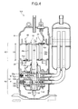
- a 2-cylinder rotary compressor 100 includes a compression mechanism 40 that generates compressed fluid and a motor 42 that drives the compression mechanism 40.
- the motor 42 includes a stator 46 fixed in a sealed casing 44 and the rotor 10 of the present invention.
- a shaft 48 that extends downward toward the compression mechanism 40.
- eccentric cranks 50a and 50b of the compression mechanism 40 are eccentric cranks 50a and 50b of the compression mechanism 40.
- the compression mechanism 40 includes two cylinders 52a and 52b that are arranged vertically.
- the eccentric cranks 50a and 50b are located inside the cylinders 52a and 52b, respectively.
- the eccentric cranks 50a and 50b are fitted with ring-like pistons 54a and 54b, respectively.
- centrifugal forces Fc1 and Fc2 act on the eccentric cranks 50a and 50b, respectively, while centrifugal forces Fp1 and Fp2 act on the pistons 54a and 54b, respectively.
- centrifugal forces Fb1 and Fb2 act on the balance weights 20 and 22 fixed above and below the rotor 10 of the motor 42, respectively.
- positions and masses of the two balance weights 20 and 22 are determined in advance to satisfy the following expressions (1) and (2):
- a rotor of a compressor motor includes a rotor laminated steel plate, a permanent magnet located inside the rotor laminated steel plate to form a plurality of magnetic poles along the circumferential direction with the rotation axis as the center, rotor end plates arranged on both end surfaces of the rotor laminated steel plate to restrict the movement of the permanent magnet in the axial direction, and balance weights provided on the outer surfaces of the rotor end plates, respectively.
- the rotor laminated steel plate and the rotor end plates are provided with at least three axial through holes that are equally spaced apart in the circumferential direction.
- the rotor laminated steel plate and the rotor end plates are fixed by three rivets passing through the axial through holes, respectively.
- the balance weight on one side is fixed to the rotor end plate on the one side by two of the three rivets.
- the balance weight on the other side is fixed to the rotor end plate on the other side by remaining one of the rivets.
- the balance weight on the other side is positioned with respect to the rotor end plate on the other side by engagement members provided thereto and those provided to the rotor end plate on the other side.
- the balance weight can be stably positioned with respect to the rotor without using a positioning jig or the like.
- the positioning by the engagement members prevents the balance weight from rotating about the rivet while the rotor is being driven to rotate.
- a rotor of a compressor motor and the way of fixing its balance weight according to the present invention are suitably applied to a rotor of a compressor motor used in rotary compressors such as scroll compressors, and especially suitable to manufacture a rotor with six magnetic poles at a low cost.
Landscapes
- Engineering & Computer Science (AREA)
- Mechanical Engineering (AREA)
- General Engineering & Computer Science (AREA)
- Power Engineering (AREA)
- Permanent Field Magnets Of Synchronous Machinery (AREA)
- Manufacture Of Motors, Generators (AREA)
- Compressor (AREA)
- Iron Core Of Rotating Electric Machines (AREA)
Abstract
Description
- The present invention relates to a rotor of a compressor motor used in rotary compressors such as scroll compressors.
- There has been known a rotor of a motor used in rotary compressors such as scroll compressors (see, for example, Patent Documents 1 to 5). A 4-pole rotor generally includes a rotor laminated steel plate, a permanent magnet arranged inside the rotor laminated steel plate to form four magnetic poles, rotor end plates located on both end surfaces of the rotor laminated steel plate, and balance weights that counteract centrifugal force acting on the eccentrically rotating part of the compression mechanism. The rotor laminated steel plate and the rotor end plates are fixed by four rivets, and the balance weights are fixed to the rotor end plates, respectively, by using two of the four rivets.
- As 6-pole rotors efficient in reducing vibration and noise, there have been known rotors having a structure in which the rotor laminated steel plate and the rotor end plates are fixed by six rivets or three rivets (see, for example, Patent Document 5).
-
- Patent Document 1: Japanese Patent Application Laid-open No.
2000-125492 - Patent Document 2: Japanese Patent Application Laid-open No.
2000-287424 - Patent Document 3: Japanese Patent Application Laid-open No.
S63-28250 - Patent Document 4: Japanese Patent Application Laid-open No.
H4-237891 - Patent Document 5: Japanese Patent Application Laid-open No.
2005-245148 - As illustrated in
Fig. 5 , two balance weights on both end surfaces of a conventional rotor of a compressor motor need to be located at positions with a phase difference of 180° taking into account the balance when the rotor is rotating. Consider the case that a 6-pole rotor is fixed by three rivets spaced substantially 120° apart, and twobalance weights rivets 4 of the three rivets. In this case, although thebalance weight 2a on one side can be provided with tworivet holes 6a on the right side where they are supposed to be, thebalance weight 2a on the other side is necessitated to have rivetholes 6b at positions on the side opposite the right side. This becomes a necessity to increase the size of the balance weight to achieve a predetermined centrifugal force, resulting in a higher cost. - In view of this, the
balance weight 2b on the other side may be fixed by asingle rivet 8. In this case, however, when fixed by therivet 8, thebalance weight 2b rotates about therivet 8, which makes it difficult to stably position thebalance weight 2b. - As illustrated in
Fig. 6 , thebalance weight 2b to be fixed by thesingle rivet 8 may be shaped in a cylinder to reduce the effect of rotation about therivet 8. In this case, however, the cylinder has to be thick to ensure the necessary mass and may result in a higher cost because of the difficulty in press molding. Besides, when the rotor is rotating, resistance from surrounding refrigerant gas increases, and thereby the efficiency of the compressor decreases. - The present invention has been made to solve the above problems in the conventional technology and it is an object of the present invention to provide a rotor of a compressor motor at a low cost in which a balance weight is stably positioned.
- To solve the problems and achieve the object mentioned above, according to the invention set forth in claim 1, a rotor of a compressor motor includes: a rotor laminated steel plate; a permanent magnet that is located inside the rotor laminated steel plate to form a plurality of magnetic poles along the circumferential direction with the rotation axis as the center; rotor end plates that are arranged on both end surfaces of the rotor laminated steel plate, respectively, to restrict the movement of the permanent magnet in the axial direction; and balance weights that are provided on the outer surfaces of the rotor end plates, respectively. The rotor laminated steel plate and the rotor end plates are provided with at least three axial through holes that are equally spaced apart in the circumferential direction. The rotor laminated steel plate and the rotor end plates are fixed by three rivets passing through the axial through holes, respectively. The balance weight on one side is fixed to the rotor end plate on the one side by two of the three rivets. The balance weight on the other side is fixed to the rotor end plate on the other side by remaining one of the rivets, and is positioned with respect to the rotor end plate on the other side by engagement members provided to the balance weight on the other side and the rotor end plate on the other side.
- According to the invention set forth in claim 2, in the rotor of a compressor motor of claim 1, the engagement members include either a protrusion, or a recess or a through hole provided to the balance weight, and either a recess or a through hole, or a protrusion provided to the rotor end plate. By the engagement between the protrusion of the balance weight and the recess or the through hole of the rotor end plate, or between the recess or the through hole of the balance weight and the protrusion of the rotor end plate, the balance weight is positioned with respect to the rotor end plate.
- According to the present invention, a rotor of a compressor motor includes: a rotor laminated steel plate; a permanent magnet that is located inside the rotor laminated steel plate to form a plurality of magnetic poles along the circumferential direction with the rotation axis as the center; rotor end plates that are arranged on both end surfaces of the rotor laminated steel plate, respectively, to restrict the movement of the permanent magnet in the axial direction; and balance weights that are provided on the outer surfaces of the rotor end plates, respectively. The rotor laminated steel plate and the rotor end plates are provided with at least three axial through holes that are equally spaced apart in the circumferential direction. The rotor laminated steel plate and the rotor end plates are fixed by three rivets passing through the axial through holes, respectively. The balance weight on one side is fixed to the rotor end plate on the one side by two of the three rivets. The balance weight on the other side is fixed to the rotor end plate on the other side by remaining one of the rivets, and is positioned with respect to the rotor end plate on the other side by engagement members provided to the balance weight on the other side and the rotor end plate on the other side.
- With this, to fix the balance weight to the rotor with a single rivet, the balance weight can be stably positioned with respect to the rotor without using a positioning jig or the like. Moreover, according to the present invention, there is no need to make the balance weight large in size or in a specific shape such as a cylindrical shape to achieve a predetermined centrifugal force, and thereby the rotor can be obtained at a low cost. Furthermore, the positioning by the engagement members prevents the balance weight from rotating about the rivet while the rotor is being driven to rotate.
-
-
Fig. 1 is a perspective view of a rotor of a compressor motor according to an embodiment of the present invention. -
Fig. 2 is an exploded perspective view of the rotor of a compressor motor according to the embodiment of the present invention. -
Fig. 3 is an exploded perspective view of a rotor of a compressor motor according to another embodiment of the present invention. -
Fig. 4 is a side cross-sectional view of a compressor using the rotor of a compressor motor of the present invention. -
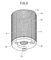
Fig. 5 is a perspective view of an example of a conventional rotor of a compressor motor. -
Fig. 6 is a perspective view of another example of a conventional rotor of a compressor motor. -
- 10
- Rotor (rotor of a compressor motor)
- 12
- Rotor laminated steel plate
- 14
- Permanent magnet
- 16, 18
- Rotor end plate
- 20
- Balance weight (balance weight on one side)
- 22
- Balance weight (balance weight on the other side)
- 24
- Axial through hole
- 26a, 26b, 26c
- Rivet
- 28
- Protrusion (engagement member)
- 30
- Shaft hole
- 32
- Recess (engagement member)
- 40
- Compression mechanism
- 42
- Motor
- 44
- Sealed casing
- 46
- Stator
- 48
- Shaft
- 50a, 50b
- Eccentric crank
- 52a, 52b
- Cylinder
- 54a, 54b
- Piston
- 100
- Compressor
- Exemplary embodiments of a rotor of a compressor motor according to the present invention will be described in detail below with reference to the accompanying drawings taking a 6-pole rotor as an example. However, the present invention is not limited to the following embodiments.
- As illustrated in
Figs. 1 and2 , arotor 10 of a compressor motor of the present invention is a rotor of a motor for use in a compressor. Therotor 10 includes a substantially cylindrical rotor laminatedsteel plate 12 having ashaft hole 30 and apermanent magnet 14 located inside the rotor laminatedsteel plate 12 to form six magnetic poles in a manner such that south and north poles are alternately arranged along the circumferential direction with a rotation axis Z as the center. - The
rotor 10 further includes perforated disc-likerotor end plates steel plate 12, respectively, to restrict the movement of thepermanent magnet 14 in the axial direction, and arched plate-like balance weights rotor end plates balance weights balance weights - The rotor laminated
steel plate 12 and therotor end plates holes 24 that are equally spaced apart (spaced 120° apart) in the circumferential direction. The axial throughholes 24 are located at positions not interfering with thepermanent magnet 14. The number of the axial throughholes 24 may be three or more and, as illustrated inFig. 2 , there may be five of them. - The rotor laminated
steel plate 12 and therotor end plates rivets holes 24, respectively. - The
balance weight 20 on one side is fixed to therotor end plate 16 on the one side by the tworivets - At two end positions of the
balance weight 22 on the other side,protrusions 28 are formed as engagement members by press molding or the like. In therotor end plate 18 on the other side, recesses 32 are formed at two positions facing theprotrusions 28. Therecesses 32 may be through holes passing through therotor end plate 18 as well as recesses formed by press molding or the like. - The
balance weight 22 on the other side is fixed to therotor end plate 18 on the other side by the remaining onerivet 26c, and is positioned with respect to therotor end plate 18 on the other side by the engagement of theprotrusions 28 with therecesses 32. - As described above, the
balance weight 22 on the other side is provided with theprotrusions 28 by press molding, while therotor end plate 18 is provided with therecesses 32. By the engagement between theprotrusions 28 and therecesses 32, thebalance weight 22 on the other side can be positioned with respect to therotor end plate 18, and is prevented from rotating about therivet 26c. Accordingly, to fix thebalance weight 22 to therotor 10 with thesingle rivet 26c, thebalance weight 22 can be stably positioned with respect to therotor 10 without using a positioning jig or the like. Moreover, there is no need to make the balance weight large in size or in a specific shape such as a cylindrical shape to achieve a predetermined centrifugal force, and thereby the rotor can be obtained at a low cost. Furthermore, the positioning by the engagement of theprotrusions 28 with therecesses 32 prevents thebalance weight 22 from rotating about therivet 26c while the rotor is being driven to rotate. - As illustrated in
Fig. 3 , the recesses and the protrusions may exchange their positions. For example, thebalance weight 22 may be provided withrecesses 28a, and therotor end plate 18 may be provided withprotrusions 32a so that thebalance weight 22 can be positioned by the engagement between therecesses 28a and theprotrusions 32a. In this case, thebalance weight 22 may be provided with through holes instead of therecesses 28a - With reference to
Fig. 4 , a description will be given of the case where therotor 10 of a compressor motor of the present invention is applied to a 2-cylinder rotary compressor. - As illustrated in
Fig. 4 , a 2-cylinder rotary compressor 100 includes acompression mechanism 40 that generates compressed fluid and amotor 42 that drives thecompression mechanism 40. Themotor 42 includes astator 46 fixed in a sealedcasing 44 and therotor 10 of the present invention. To theshaft hole 30 of therotor 10 is fixed ashaft 48 that extends downward toward thecompression mechanism 40. Below theshaft 48 areeccentric cranks compression mechanism 40. - The
compression mechanism 40 includes twocylinders cylinders like pistons - When the
shaft 48 of therotor 10 is driven by themotor 42 and rotates, centrifugal forces Fc1 and Fc2 act on theeccentric cranks pistons - Meanwhile, centrifugal forces Fb1 and Fb2 act on the
balance weights rotor 10 of themotor 42, respectively. - To ensure the balance of the entire compressor, positions and masses of the two
balance weights -


- As described above, according to the present invention, a rotor of a compressor motor includes a rotor laminated steel plate, a permanent magnet located inside the rotor laminated steel plate to form a plurality of magnetic poles along the circumferential direction with the rotation axis as the center, rotor end plates arranged on both end surfaces of the rotor laminated steel plate to restrict the movement of the permanent magnet in the axial direction, and balance weights provided on the outer surfaces of the rotor end plates, respectively. The rotor laminated steel plate and the rotor end plates are provided with at least three axial through holes that are equally spaced apart in the circumferential direction. The rotor laminated steel plate and the rotor end plates are fixed by three rivets passing through the axial through holes, respectively. The balance weight on one side is fixed to the rotor end plate on the one side by two of the three rivets. The balance weight on the other side is fixed to the rotor end plate on the other side by remaining one of the rivets. The balance weight on the other side is positioned with respect to the rotor end plate on the other side by engagement members provided thereto and those provided to the rotor end plate on the other side.
- With this, to fix the balance weight to the rotor with a single rivet, the balance weight can be stably positioned with respect to the rotor without using a positioning jig or the like. Moreover, according to the present invention, there is no need to make the balance weight large in size or in a specific shape such as a cylindrical shape to achieve a predetermined centrifugal force, and thereby the rotor can be obtained at a low cost. Furthermore, the positioning by the engagement members prevents the balance weight from rotating about the rivet while the rotor is being driven to rotate.
- As described above, a rotor of a compressor motor and the way of fixing its balance weight according to the present invention are suitably applied to a rotor of a compressor motor used in rotary compressors such as scroll compressors, and especially suitable to manufacture a rotor with six magnetic poles at a low cost.
Claims (2)
- A rotor of a compressor motor comprising:a rotor laminated steel plate;a permanent magnet that is located inside the rotor laminated steel plate to form a plurality of magnetic poles along a circumferential direction with a rotation axis as a center;rotor end plates that are arranged on both end surfaces of the rotor laminated steel plate, respectively, to restrict movement of the permanent magnet in an axial direction; andbalance weights that are provided on outer surfaces of the rotor end plates, respectively, whereinthe rotor laminated steel plate and the rotor end plates are provided with at least three axial through holes that are equally spaced apart in the circumferential direction,the rotor laminated steel plate and the rotor end plates are fixed by three rivets passing through the axial through holes, respectively,one of the balance weights on one side is fixed to one of the rotor end plates on the one side by two of the three rivets,another of the balance weights on other side is fixed to another of the rotor end plates on the other side by remaining one of the rivets, and is positioned with respect to the rotor end plate on the other side by engagement members provided to the balance weight on the other side and the rotor end plate on the other side.
- The rotor of a compressor motor according to claim 1, wherein
the engagement members include either a protrusion, or a recess or a through hole provided to the balance weight, and either a recess or a through hole, or a protrusion provided to the rotor end plate, and
by engagement between the protrusion of the balance weight and the recess or the through hole of the rotor end plate, or between the recess or the through hole of the balance weight and the protrusion of the rotor end plate, the balance weight is positioned with respect to the rotor end plate.
Applications Claiming Priority (2)
| Application Number | Priority Date | Filing Date | Title |
|---|---|---|---|
| JP2009086485A JP4539781B1 (en) | 2009-03-31 | 2009-03-31 | Compressor motor rotor |
| PCT/JP2010/055250 WO2010113765A1 (en) | 2009-03-31 | 2010-03-25 | Rotor for compressor motors |
Publications (3)
| Publication Number | Publication Date |
|---|---|
| EP2416472A1 true EP2416472A1 (en) | 2012-02-08 |
| EP2416472A4 EP2416472A4 (en) | 2017-10-18 |
| EP2416472B1 EP2416472B1 (en) | 2019-01-02 |
Family
ID=42824752
Family Applications (1)
| Application Number | Title | Priority Date | Filing Date |
|---|---|---|---|
| EP10758538.2A Active EP2416472B1 (en) | 2009-03-31 | 2010-03-25 | Rotor for compressor motors |
Country Status (6)
| Country | Link |
|---|---|
| US (1) | US9385573B2 (en) |
| EP (1) | EP2416472B1 (en) |
| JP (1) | JP4539781B1 (en) |
| CN (1) | CN102362417B (en) |
| AU (1) | AU2010231800B2 (en) |
| WO (1) | WO2010113765A1 (en) |
Cited By (5)
| Publication number | Priority date | Publication date | Assignee | Title |
|---|---|---|---|---|
| WO2014033016A3 (en) * | 2012-08-28 | 2014-11-20 | Siemens Aktiengesellschaft | Rotor of an electric machine, and electric machine |
| WO2014033015A3 (en) * | 2012-08-28 | 2014-12-11 | Siemens Aktiengesellschaft | Rotor of an electric machine, and electric machine |
| EP3062426A1 (en) * | 2015-02-27 | 2016-08-31 | Johnson Electric S.A. | Single-phase brushless motor |
| WO2016207023A1 (en) * | 2015-06-25 | 2016-12-29 | C. & E. Fein Gmbh | Rotor for an electronically commutated electric motor and method for producing such a rotor |
| EP3121935A4 (en) * | 2014-03-20 | 2017-10-18 | Fujitsu General Limited | Rotor for compressor motor |
Families Citing this family (29)
| Publication number | Priority date | Publication date | Assignee | Title |
|---|---|---|---|---|
| WO2013032353A1 (en) * | 2011-08-26 | 2013-03-07 | General Electric Company | Permanent magent rotor having a combined laminated stack and method of assembly |
| DE102012219092A1 (en) * | 2012-10-19 | 2014-04-24 | Magna Powertrain Ag & Co. Kg | Thrust washer for use in rotor of e.g. electric motor in electric vehicle, has radially extending area designed as spring area between inner and outer diameter of washer, and another radially extending area designed as impact area |
| US20140124231A1 (en) | 2012-11-06 | 2014-05-08 | Milwaukee Electric Tool Corporation | Electric motor for a power tool |
| US10432045B2 (en) | 2012-11-06 | 2019-10-01 | Milwaukee Electric Tool Corporation | Electric motor for a power tool |
| CN104097025B (en) * | 2013-04-07 | 2017-12-08 | 吴为国 | A kind of Roots blower and aeration oxygen replenishing device |
| US20140359969A1 (en) * | 2013-06-11 | 2014-12-11 | Samsung Electronics Co., Ltd. | Motor apparatus and cleaner having the same |
| JP6175993B2 (en) * | 2013-08-30 | 2017-08-09 | 株式会社デンソー | Brushless motor rotor |
| JP6121967B2 (en) * | 2014-10-02 | 2017-04-26 | ファナック株式会社 | Rotor with balancer weight and motor |
| CN104314819B (en) * | 2014-10-11 | 2017-05-31 | 广东美芝制冷设备有限公司 | Rotor balance and rotor assembly and rotary compressor with it |
| JP2016092966A (en) * | 2014-11-05 | 2016-05-23 | 日本電産テクノモータ株式会社 | Rotor and motor |
| JP6884497B2 (en) * | 2014-11-13 | 2021-06-09 | 三菱重工サーマルシステムズ株式会社 | Motor rotors, motors using them, and electric compressors |
| CN104753277B (en) * | 2015-03-13 | 2018-06-15 | 广东威灵电机制造有限公司 | For the rotor of squirrel cage motor and with its squirrel cage motor |
| CN104753278B (en) * | 2015-03-13 | 2018-09-11 | 广东威灵电机制造有限公司 | Rotor for squirrel cage motor and the squirrel cage motor with it |
| US10954944B2 (en) * | 2015-04-27 | 2021-03-23 | Emerson Climate Technologies, Inc. | Compressor having counterweight assembly |
| WO2016203563A1 (en) * | 2015-06-17 | 2016-12-22 | 三菱電機株式会社 | Permanent magnet embedded-type electric motor for compressor, compressor, and refrigeration cycle device |
| CN106968952A (en) * | 2016-01-14 | 2017-07-21 | 艾默生环境优化技术(苏州)有限公司 | Rotary machine |
| WO2017121335A1 (en) * | 2016-01-14 | 2017-07-20 | 艾默生环境优化技术(苏州)有限公司 | Rotary machine |
| WO2018035732A1 (en) * | 2016-08-24 | 2018-03-01 | 广东美芝制冷设备有限公司 | Motor rotor for use in compressor, motor for use in compressor, and compressor |
| CN108631500B (en) * | 2017-03-15 | 2024-06-14 | 三菱电机(广州)压缩机有限公司 | Compressor and its rotor assembly |
| JP6753359B2 (en) | 2017-06-05 | 2020-09-09 | 株式会社豊田自動織機 | Motor rotor structure |
| EP3713047A4 (en) | 2017-11-24 | 2021-01-13 | Anhui Meizhi Precision Manufacturing Co., Ltd. | Permanent magnet for motor, rotor assembly having same, motor, and compressor |
| CN107707051A (en) * | 2017-11-24 | 2018-02-16 | 安徽美芝精密制造有限公司 | For motor permanent magnet and there is its rotor assembly, motor and compressor |
| DE102017222683A1 (en) * | 2017-12-13 | 2019-06-13 | Baumüller Nürnberg GmbH | Electric machine |
| JP2020065322A (en) * | 2018-10-15 | 2020-04-23 | 株式会社鷺宮製作所 | Vibration power generation element and vibration power generation device |
| KR102665224B1 (en) * | 2019-09-02 | 2024-05-13 | 엘지전자 주식회사 | Electric motor and compressor having the same |
| TR202012067A2 (en) * | 2020-07-29 | 2022-02-21 | Arçeli̇k Anoni̇m Şi̇rketi̇ | HERMETIC COMPRESSOR CONTAINING A MAGNET WITH A COATED SURFACE |
| CN113258715B (en) * | 2021-05-28 | 2026-02-06 | 珠海格力节能环保制冷技术研究中心有限公司 | Rotor balance block, motor rotor, motor, compressor and air conditioner |
| WO2023231510A1 (en) * | 2022-05-31 | 2023-12-07 | 安徽威灵汽车部件有限公司 | Rotor assembly, permanent magnet synchronous electric motor, electric motor driven compressor, air conditioning system and vehicle |
| US20260045849A1 (en) * | 2024-08-12 | 2026-02-12 | Fca Us Llc | Vibration absorber for vehicle electric generator |
Family Cites Families (26)
| Publication number | Priority date | Publication date | Assignee | Title |
|---|---|---|---|---|
| DE2814062C2 (en) * | 1978-03-31 | 1983-12-29 | Siemens AG, 1000 Berlin und 8000 München | Arrangement for centered and mutually plane-parallel installation of the end shields on the stator core of an electric motor without a housing |
| DE3227681A1 (en) * | 1982-07-24 | 1984-02-02 | Robert Bosch Gmbh, 7000 Stuttgart | METHOD FOR PRODUCING A LAMINATE PACKAGE FOR ANCHOR ELECTRICAL MACHINES |
| JPS6328250A (en) | 1986-07-21 | 1988-02-05 | Matsushita Refrig Co | Balance weight of electric element of hermetic electric compressor |
| JPS6383972A (en) | 1986-09-27 | 1988-04-14 | Toshiba Corp | Detecting circuit for pll data area of digital reproducing device |
| JPS6383972U (en) * | 1986-11-19 | 1988-06-01 | ||
| JPH04237891A (en) | 1991-01-22 | 1992-08-26 | Daikin Ind Ltd | Motor driven compressor |
| JPH05328645A (en) * | 1992-05-25 | 1993-12-10 | Aichi Emerson Electric Co Ltd | Rotor of motor for compressor |
| JPH06328250A (en) | 1993-05-18 | 1994-11-29 | Honda Motor Co Ltd | Welding position detection method and device |
| JPH09308152A (en) * | 1996-05-13 | 1997-11-28 | Aichi Emerson Electric Co Ltd | Motor rotor |
| JP4213798B2 (en) * | 1998-10-08 | 2009-01-21 | アイチエレック株式会社 | Hermetic electric compressor |
| JP2000125492A (en) | 1998-10-13 | 2000-04-28 | Fujitsu General Ltd | Motor balancer |
| JP2000287424A (en) | 1999-03-30 | 2000-10-13 | Sanyo Electric Co Ltd | Rotor of rotary compressor and manufacture thereof |
| JP2001197693A (en) * | 2000-01-14 | 2001-07-19 | Toshiba Tec Corp | Rotor for brushless motor and brushless motor |
| JP2001342954A (en) * | 2000-05-31 | 2001-12-14 | Sanyo Electric Co Ltd | Electric compressor and cooling system using the same |
| EP1330010A4 (en) * | 2000-09-01 | 2007-06-20 | Matsushita Electric Industrial Co Ltd | ELECTRIC MOTOR |
| US20020096893A1 (en) * | 2001-01-22 | 2002-07-25 | Taiwan Fu Hsing Industrial Co. Ltd. | Auxiliary lock structure |
| ES2362171T3 (en) * | 2001-03-30 | 2011-06-29 | Sanyo Electric Co., Ltd. | SYNCHRONOUS INDUCTION MOTOR, MANUFACTURING PROCEDURE AND DRIVE UNIT FOR THE SAME, AND HERMETIC ELECTRIC COMPRESSOR. |
| JP4143827B2 (en) | 2003-03-14 | 2008-09-03 | 株式会社富士通ゼネラル | Scroll compressor |
| JP4485225B2 (en) | 2004-02-27 | 2010-06-16 | 三菱電機株式会社 | Permanent magnet motor, hermetic compressor and fan motor |
| JP2006152838A (en) * | 2004-11-26 | 2006-06-15 | Fujitsu General Ltd | Compressor |
| CN2881019Y (en) | 2005-05-09 | 2007-03-21 | 支玉柱 | Elastic automatic locking wind hook |
| CN101443982B (en) * | 2005-05-12 | 2012-10-31 | Lg电子株式会社 | Rotor of synchronous reluctance motor |
| JP4850528B2 (en) * | 2006-02-08 | 2012-01-11 | トヨタ自動車株式会社 | Manufacturing method of rotor |
| CN101110541A (en) * | 2006-07-19 | 2008-01-23 | 乐金电子(天津)电器有限公司 | Compressor motor rotor balance weight structure |
| KR20080012547A (en) * | 2006-08-03 | 2008-02-12 | 삼성광주전자 주식회사 | Hermetic compressor |
| JP4687810B2 (en) * | 2009-03-31 | 2011-05-25 | 株式会社富士通ゼネラル | Electric motor rotor |
-
2009
- 2009-03-31 JP JP2009086485A patent/JP4539781B1/en active Active
-
2010
- 2010-03-25 AU AU2010231800A patent/AU2010231800B2/en active Active
- 2010-03-25 US US13/262,447 patent/US9385573B2/en active Active
- 2010-03-25 CN CN201080013334.2A patent/CN102362417B/en active Active
- 2010-03-25 WO PCT/JP2010/055250 patent/WO2010113765A1/en not_active Ceased
- 2010-03-25 EP EP10758538.2A patent/EP2416472B1/en active Active
Non-Patent Citations (1)
| Title |
|---|
| See references of WO2010113765A1 * |
Cited By (8)
| Publication number | Priority date | Publication date | Assignee | Title |
|---|---|---|---|---|
| WO2014033016A3 (en) * | 2012-08-28 | 2014-11-20 | Siemens Aktiengesellschaft | Rotor of an electric machine, and electric machine |
| WO2014033015A3 (en) * | 2012-08-28 | 2014-12-11 | Siemens Aktiengesellschaft | Rotor of an electric machine, and electric machine |
| US9601954B2 (en) | 2012-08-28 | 2017-03-21 | Siemens Aktiengesellschaft | Rotor of an electric machine, and electric machine |
| US9712020B2 (en) | 2012-08-28 | 2017-07-18 | Siemens Aktiengesellschaft | Rotor of an electric machine, and electric machine |
| EP3121935A4 (en) * | 2014-03-20 | 2017-10-18 | Fujitsu General Limited | Rotor for compressor motor |
| US10141802B2 (en) | 2014-03-20 | 2018-11-27 | Fujitsu General Limited | Rotor of electric motor for compressor |
| EP3062426A1 (en) * | 2015-02-27 | 2016-08-31 | Johnson Electric S.A. | Single-phase brushless motor |
| WO2016207023A1 (en) * | 2015-06-25 | 2016-12-29 | C. & E. Fein Gmbh | Rotor for an electronically commutated electric motor and method for producing such a rotor |
Also Published As
| Publication number | Publication date |
|---|---|
| CN102362417A (en) | 2012-02-22 |
| US9385573B2 (en) | 2016-07-05 |
| CN102362417B (en) | 2014-12-17 |
| EP2416472A4 (en) | 2017-10-18 |
| WO2010113765A1 (en) | 2010-10-07 |
| US20120098359A1 (en) | 2012-04-26 |
| JP4539781B1 (en) | 2010-09-08 |
| EP2416472B1 (en) | 2019-01-02 |
| AU2010231800B2 (en) | 2013-09-05 |
| AU2010231800A1 (en) | 2011-10-13 |
| JP2010239813A (en) | 2010-10-21 |
Similar Documents
| Publication | Publication Date | Title |
|---|---|---|
| EP2416472B1 (en) | Rotor for compressor motors | |
| JP5858076B2 (en) | Compressor motor rotor | |
| EP2416013A1 (en) | Electric motor rotor and compressor provided with the same | |
| EP2749735B1 (en) | Compressor | |
| EP2312727A1 (en) | Stator, motor, and compressor | |
| JP6524268B2 (en) | Hermetic compressor and refrigeration cycle device | |
| EP3163083B1 (en) | Electric compressor | |
| JP4270203B2 (en) | Motor and compressor | |
| EP2749736A1 (en) | Compressor | |
| CN105992872B (en) | Compressor | |
| JP2013211989A (en) | Interior permanent magnet motor and electrical compressor comprising the same | |
| JP6502078B2 (en) | Compressor | |
| EP4130478B1 (en) | Rotary compressor | |
| CN204316209U (en) | Compressor | |
| KR100673726B1 (en) | Spring support structure of linear compressor | |
| KR100447207B1 (en) | Scroll compressor with outer rotor type motor | |
| WO2011007914A1 (en) | Reciprocating compressor | |
| Kudarauskas et al. | Innovative Free-piston Compressor Based on Generalized Conception of Compressors Driven by an Oscillating Electrical Motor | |
| KR20060086692A (en) | Spring support structure of linear compressor |
Legal Events
| Date | Code | Title | Description |
|---|---|---|---|
| PUAI | Public reference made under article 153(3) epc to a published international application that has entered the european phase |
Free format text: ORIGINAL CODE: 0009012 |
|
| 17P | Request for examination filed |
Effective date: 20110921 |
|
| AK | Designated contracting states |
Kind code of ref document: A1 Designated state(s): AT BE BG CH CY CZ DE DK EE ES FI FR GB GR HR HU IE IS IT LI LT LU LV MC MK MT NL NO PL PT RO SE SI SK SM TR |
|
| DAX | Request for extension of the european patent (deleted) | ||
| RA4 | Supplementary search report drawn up and despatched (corrected) |
Effective date: 20170915 |
|
| RIC1 | Information provided on ipc code assigned before grant |
Ipc: H02K 15/16 20060101AFI20170908BHEP Ipc: H02K 1/27 20060101ALI20170908BHEP Ipc: H02K 7/04 20060101ALI20170908BHEP Ipc: F04C 23/00 20060101ALI20170908BHEP Ipc: H02K 7/14 20060101ALI20170908BHEP Ipc: F04C 29/00 20060101ALI20170908BHEP Ipc: F04B 35/04 20060101ALI20170908BHEP |
|
| GRAP | Despatch of communication of intention to grant a patent |
Free format text: ORIGINAL CODE: EPIDOSNIGR1 |
|
| STAA | Information on the status of an ep patent application or granted ep patent |
Free format text: STATUS: GRANT OF PATENT IS INTENDED |
|
| INTG | Intention to grant announced |
Effective date: 20180727 |
|
| RIN1 | Information on inventor provided before grant (corrected) |
Inventor name: MOROZUMI, NAOYA |
|
| GRAS | Grant fee paid |
Free format text: ORIGINAL CODE: EPIDOSNIGR3 |
|
| GRAA | (expected) grant |
Free format text: ORIGINAL CODE: 0009210 |
|
| STAA | Information on the status of an ep patent application or granted ep patent |
Free format text: STATUS: THE PATENT HAS BEEN GRANTED |
|
| AK | Designated contracting states |
Kind code of ref document: B1 Designated state(s): AT BE BG CH CY CZ DE DK EE ES FI FR GB GR HR HU IE IS IT LI LT LU LV MC MK MT NL NO PL PT RO SE SI SK SM TR |
|
| REG | Reference to a national code |
Ref country code: GB Ref legal event code: FG4D |
|
| REG | Reference to a national code |
Ref country code: CH Ref legal event code: EP Ref country code: AT Ref legal event code: REF Ref document number: 1085662 Country of ref document: AT Kind code of ref document: T Effective date: 20190115 |
|
| REG | Reference to a national code |
Ref country code: IE Ref legal event code: FG4D |
|
| REG | Reference to a national code |
Ref country code: DE Ref legal event code: R096 Ref document number: 602010056247 Country of ref document: DE |
|
| REG | Reference to a national code |
Ref country code: NL Ref legal event code: MP Effective date: 20190102 |
|
| REG | Reference to a national code |
Ref country code: LT Ref legal event code: MG4D |
|
| REG | Reference to a national code |
Ref country code: AT Ref legal event code: MK05 Ref document number: 1085662 Country of ref document: AT Kind code of ref document: T Effective date: 20190102 |
|
| PG25 | Lapsed in a contracting state [announced via postgrant information from national office to epo] |
Ref country code: NL Free format text: LAPSE BECAUSE OF FAILURE TO SUBMIT A TRANSLATION OF THE DESCRIPTION OR TO PAY THE FEE WITHIN THE PRESCRIBED TIME-LIMIT Effective date: 20190102 |
|
| PG25 | Lapsed in a contracting state [announced via postgrant information from national office to epo] |
Ref country code: NO Free format text: LAPSE BECAUSE OF FAILURE TO SUBMIT A TRANSLATION OF THE DESCRIPTION OR TO PAY THE FEE WITHIN THE PRESCRIBED TIME-LIMIT Effective date: 20190402 Ref country code: FI Free format text: LAPSE BECAUSE OF FAILURE TO SUBMIT A TRANSLATION OF THE DESCRIPTION OR TO PAY THE FEE WITHIN THE PRESCRIBED TIME-LIMIT Effective date: 20190102 Ref country code: SE Free format text: LAPSE BECAUSE OF FAILURE TO SUBMIT A TRANSLATION OF THE DESCRIPTION OR TO PAY THE FEE WITHIN THE PRESCRIBED TIME-LIMIT Effective date: 20190102 Ref country code: PT Free format text: LAPSE BECAUSE OF FAILURE TO SUBMIT A TRANSLATION OF THE DESCRIPTION OR TO PAY THE FEE WITHIN THE PRESCRIBED TIME-LIMIT Effective date: 20190502 Ref country code: PL Free format text: LAPSE BECAUSE OF FAILURE TO SUBMIT A TRANSLATION OF THE DESCRIPTION OR TO PAY THE FEE WITHIN THE PRESCRIBED TIME-LIMIT Effective date: 20190102 Ref country code: ES Free format text: LAPSE BECAUSE OF FAILURE TO SUBMIT A TRANSLATION OF THE DESCRIPTION OR TO PAY THE FEE WITHIN THE PRESCRIBED TIME-LIMIT Effective date: 20190102 Ref country code: LT Free format text: LAPSE BECAUSE OF FAILURE TO SUBMIT A TRANSLATION OF THE DESCRIPTION OR TO PAY THE FEE WITHIN THE PRESCRIBED TIME-LIMIT Effective date: 20190102 |
|
| PG25 | Lapsed in a contracting state [announced via postgrant information from national office to epo] |
Ref country code: HR Free format text: LAPSE BECAUSE OF FAILURE TO SUBMIT A TRANSLATION OF THE DESCRIPTION OR TO PAY THE FEE WITHIN THE PRESCRIBED TIME-LIMIT Effective date: 20190102 Ref country code: LV Free format text: LAPSE BECAUSE OF FAILURE TO SUBMIT A TRANSLATION OF THE DESCRIPTION OR TO PAY THE FEE WITHIN THE PRESCRIBED TIME-LIMIT Effective date: 20190102 Ref country code: GR Free format text: LAPSE BECAUSE OF FAILURE TO SUBMIT A TRANSLATION OF THE DESCRIPTION OR TO PAY THE FEE WITHIN THE PRESCRIBED TIME-LIMIT Effective date: 20190403 Ref country code: IS Free format text: LAPSE BECAUSE OF FAILURE TO SUBMIT A TRANSLATION OF THE DESCRIPTION OR TO PAY THE FEE WITHIN THE PRESCRIBED TIME-LIMIT Effective date: 20190502 Ref country code: BG Free format text: LAPSE BECAUSE OF FAILURE TO SUBMIT A TRANSLATION OF THE DESCRIPTION OR TO PAY THE FEE WITHIN THE PRESCRIBED TIME-LIMIT Effective date: 20190402 |
|
| REG | Reference to a national code |
Ref country code: DE Ref legal event code: R119 Ref document number: 602010056247 Country of ref document: DE |
|
| REG | Reference to a national code |
Ref country code: DE Ref legal event code: R097 Ref document number: 602010056247 Country of ref document: DE |
|
| PG25 | Lapsed in a contracting state [announced via postgrant information from national office to epo] |
Ref country code: EE Free format text: LAPSE BECAUSE OF FAILURE TO SUBMIT A TRANSLATION OF THE DESCRIPTION OR TO PAY THE FEE WITHIN THE PRESCRIBED TIME-LIMIT Effective date: 20190102 Ref country code: DK Free format text: LAPSE BECAUSE OF FAILURE TO SUBMIT A TRANSLATION OF THE DESCRIPTION OR TO PAY THE FEE WITHIN THE PRESCRIBED TIME-LIMIT Effective date: 20190102 Ref country code: IT Free format text: LAPSE BECAUSE OF FAILURE TO SUBMIT A TRANSLATION OF THE DESCRIPTION OR TO PAY THE FEE WITHIN THE PRESCRIBED TIME-LIMIT Effective date: 20190102 Ref country code: RO Free format text: LAPSE BECAUSE OF FAILURE TO SUBMIT A TRANSLATION OF THE DESCRIPTION OR TO PAY THE FEE WITHIN THE PRESCRIBED TIME-LIMIT Effective date: 20190102 Ref country code: AT Free format text: LAPSE BECAUSE OF FAILURE TO SUBMIT A TRANSLATION OF THE DESCRIPTION OR TO PAY THE FEE WITHIN THE PRESCRIBED TIME-LIMIT Effective date: 20190102 Ref country code: CZ Free format text: LAPSE BECAUSE OF FAILURE TO SUBMIT A TRANSLATION OF THE DESCRIPTION OR TO PAY THE FEE WITHIN THE PRESCRIBED TIME-LIMIT Effective date: 20190102 Ref country code: SK Free format text: LAPSE BECAUSE OF FAILURE TO SUBMIT A TRANSLATION OF THE DESCRIPTION OR TO PAY THE FEE WITHIN THE PRESCRIBED TIME-LIMIT Effective date: 20190102 Ref country code: MC Free format text: LAPSE BECAUSE OF FAILURE TO SUBMIT A TRANSLATION OF THE DESCRIPTION OR TO PAY THE FEE WITHIN THE PRESCRIBED TIME-LIMIT Effective date: 20190102 |
|
| REG | Reference to a national code |
Ref country code: CH Ref legal event code: PL |
|
| PLBE | No opposition filed within time limit |
Free format text: ORIGINAL CODE: 0009261 |
|
| STAA | Information on the status of an ep patent application or granted ep patent |
Free format text: STATUS: NO OPPOSITION FILED WITHIN TIME LIMIT |
|
| PG25 | Lapsed in a contracting state [announced via postgrant information from national office to epo] |
Ref country code: LU Free format text: LAPSE BECAUSE OF NON-PAYMENT OF DUE FEES Effective date: 20190325 Ref country code: SM Free format text: LAPSE BECAUSE OF FAILURE TO SUBMIT A TRANSLATION OF THE DESCRIPTION OR TO PAY THE FEE WITHIN THE PRESCRIBED TIME-LIMIT Effective date: 20190102 |
|
| 26N | No opposition filed |
Effective date: 20191003 |
|
| REG | Reference to a national code |
Ref country code: BE Ref legal event code: MM Effective date: 20190331 |
|
| PG25 | Lapsed in a contracting state [announced via postgrant information from national office to epo] |
Ref country code: LI Free format text: LAPSE BECAUSE OF NON-PAYMENT OF DUE FEES Effective date: 20190331 Ref country code: IE Free format text: LAPSE BECAUSE OF NON-PAYMENT OF DUE FEES Effective date: 20190325 Ref country code: CH Free format text: LAPSE BECAUSE OF NON-PAYMENT OF DUE FEES Effective date: 20190331 Ref country code: DE Free format text: LAPSE BECAUSE OF NON-PAYMENT OF DUE FEES Effective date: 20191001 |
|
| PG25 | Lapsed in a contracting state [announced via postgrant information from national office to epo] |
Ref country code: BE Free format text: LAPSE BECAUSE OF NON-PAYMENT OF DUE FEES Effective date: 20190331 Ref country code: SI Free format text: LAPSE BECAUSE OF FAILURE TO SUBMIT A TRANSLATION OF THE DESCRIPTION OR TO PAY THE FEE WITHIN THE PRESCRIBED TIME-LIMIT Effective date: 20190102 |
|
| PG25 | Lapsed in a contracting state [announced via postgrant information from national office to epo] |
Ref country code: TR Free format text: LAPSE BECAUSE OF FAILURE TO SUBMIT A TRANSLATION OF THE DESCRIPTION OR TO PAY THE FEE WITHIN THE PRESCRIBED TIME-LIMIT Effective date: 20190102 |
|
| PG25 | Lapsed in a contracting state [announced via postgrant information from national office to epo] |
Ref country code: MT Free format text: LAPSE BECAUSE OF NON-PAYMENT OF DUE FEES Effective date: 20190325 |
|
| PG25 | Lapsed in a contracting state [announced via postgrant information from national office to epo] |
Ref country code: CY Free format text: LAPSE BECAUSE OF FAILURE TO SUBMIT A TRANSLATION OF THE DESCRIPTION OR TO PAY THE FEE WITHIN THE PRESCRIBED TIME-LIMIT Effective date: 20190102 |
|
| PG25 | Lapsed in a contracting state [announced via postgrant information from national office to epo] |
Ref country code: HU Free format text: LAPSE BECAUSE OF FAILURE TO SUBMIT A TRANSLATION OF THE DESCRIPTION OR TO PAY THE FEE WITHIN THE PRESCRIBED TIME-LIMIT; INVALID AB INITIO Effective date: 20100325 |
|
| PG25 | Lapsed in a contracting state [announced via postgrant information from national office to epo] |
Ref country code: MK Free format text: LAPSE BECAUSE OF FAILURE TO SUBMIT A TRANSLATION OF THE DESCRIPTION OR TO PAY THE FEE WITHIN THE PRESCRIBED TIME-LIMIT Effective date: 20190102 |
|
| PGFP | Annual fee paid to national office [announced via postgrant information from national office to epo] |
Ref country code: FR Payment date: 20250210 Year of fee payment: 16 |
|
| PGFP | Annual fee paid to national office [announced via postgrant information from national office to epo] |
Ref country code: GB Payment date: 20250130 Year of fee payment: 16 |