EP2415600B1 - Kompaktes Laminiergerät - Google Patents
Kompaktes Laminiergerät Download PDFInfo
- Publication number
- EP2415600B1 EP2415600B1 EP11173388.7A EP11173388A EP2415600B1 EP 2415600 B1 EP2415600 B1 EP 2415600B1 EP 11173388 A EP11173388 A EP 11173388A EP 2415600 B1 EP2415600 B1 EP 2415600B1
- Authority
- EP
- European Patent Office
- Prior art keywords
- housing
- flap
- support surface
- laminating
- front flap
- Prior art date
- Legal status (The legal status is an assumption and is not a legal conclusion. Google has not performed a legal analysis and makes no representation as to the accuracy of the status listed.)
- Active
Links
Images
Classifications
-
- B—PERFORMING OPERATIONS; TRANSPORTING
- B32—LAYERED PRODUCTS
- B32B—LAYERED PRODUCTS, i.e. PRODUCTS BUILT-UP OF STRATA OF FLAT OR NON-FLAT, e.g. CELLULAR OR HONEYCOMB, FORM
- B32B37/00—Methods or apparatus for laminating, e.g. by curing or by ultrasonic bonding
- B32B37/14—Methods or apparatus for laminating, e.g. by curing or by ultrasonic bonding characterised by the properties of the layers
- B32B37/16—Methods or apparatus for laminating, e.g. by curing or by ultrasonic bonding characterised by the properties of the layers with all layers existing as coherent layers before laminating
- B32B37/18—Methods or apparatus for laminating, e.g. by curing or by ultrasonic bonding characterised by the properties of the layers with all layers existing as coherent layers before laminating involving the assembly of discrete sheets or panels only
- B32B37/182—Methods or apparatus for laminating, e.g. by curing or by ultrasonic bonding characterised by the properties of the layers with all layers existing as coherent layers before laminating involving the assembly of discrete sheets or panels only one or more of the layers being plastic
-
- B—PERFORMING OPERATIONS; TRANSPORTING
- B32—LAYERED PRODUCTS
- B32B—LAYERED PRODUCTS, i.e. PRODUCTS BUILT-UP OF STRATA OF FLAT OR NON-FLAT, e.g. CELLULAR OR HONEYCOMB, FORM
- B32B37/00—Methods or apparatus for laminating, e.g. by curing or by ultrasonic bonding
- B32B37/0046—Methods or apparatus for laminating, e.g. by curing or by ultrasonic bonding characterised by constructional aspects of the apparatus
-
- B—PERFORMING OPERATIONS; TRANSPORTING
- B32—LAYERED PRODUCTS
- B32B—LAYERED PRODUCTS, i.e. PRODUCTS BUILT-UP OF STRATA OF FLAT OR NON-FLAT, e.g. CELLULAR OR HONEYCOMB, FORM
- B32B37/00—Methods or apparatus for laminating, e.g. by curing or by ultrasonic bonding
- B32B37/0046—Methods or apparatus for laminating, e.g. by curing or by ultrasonic bonding characterised by constructional aspects of the apparatus
- B32B2037/0061—Methods or apparatus for laminating, e.g. by curing or by ultrasonic bonding characterised by constructional aspects of the apparatus the apparatus being an office laminator
-
- B—PERFORMING OPERATIONS; TRANSPORTING
- B32—LAYERED PRODUCTS
- B32B—LAYERED PRODUCTS, i.e. PRODUCTS BUILT-UP OF STRATA OF FLAT OR NON-FLAT, e.g. CELLULAR OR HONEYCOMB, FORM
- B32B2317/00—Animal or vegetable based
- B32B2317/12—Paper, e.g. cardboard
-
- B—PERFORMING OPERATIONS; TRANSPORTING
- B32—LAYERED PRODUCTS
- B32B—LAYERED PRODUCTS, i.e. PRODUCTS BUILT-UP OF STRATA OF FLAT OR NON-FLAT, e.g. CELLULAR OR HONEYCOMB, FORM
- B32B37/00—Methods or apparatus for laminating, e.g. by curing or by ultrasonic bonding
- B32B37/0007—Methods or apparatus for laminating, e.g. by curing or by ultrasonic bonding involving treatment or provisions in order to avoid deformation or air inclusion, e.g. to improve surface quality
- B32B37/0015—Methods or apparatus for laminating, e.g. by curing or by ultrasonic bonding involving treatment or provisions in order to avoid deformation or air inclusion, e.g. to improve surface quality to avoid warp or curl
-
- B—PERFORMING OPERATIONS; TRANSPORTING
- B32—LAYERED PRODUCTS
- B32B—LAYERED PRODUCTS, i.e. PRODUCTS BUILT-UP OF STRATA OF FLAT OR NON-FLAT, e.g. CELLULAR OR HONEYCOMB, FORM
- B32B37/00—Methods or apparatus for laminating, e.g. by curing or by ultrasonic bonding
- B32B37/08—Methods or apparatus for laminating, e.g. by curing or by ultrasonic bonding characterised by the cooling method
Definitions
- the invention relates to a laminating apparatus according to the preamble of claim 1.
- Laminators are used to connect laminates, which is usually made of paper and plastic film, to a laminate in which the paper is received in the plastic film and tightly welded. They have a laminating device with heated laminating rollers, of which at least one is driven by a motor.
- the laminating apparatus is accommodated in a housing having an insertion slot for the laminate and a discharge slot for the laminate. Between the insertion slot and the ejection slot extends a passageway through which the laminate passes through to the laminating rollers and the laminate from the laminating rollers. When passing through the laminating rollers the laminate is welded to the laminate.
- the insertion slot dirt can penetrate in addition to the Laminiergut, on the one hand pollute the laminating and can lead to technical defects.
- dirt which has penetrated through the insertion slot can be taken along by the lamination material and welded to the lamination material during lamination between the laminating rollers. Such a soiled laminate is unsightly.
- the JP 2005-343133 A discloses a laminating apparatus having a front flap and a rear flap, which flaps are pivotable. The flaps are separated from each other in the closed state by a web of the housing.
- the invention is based on the idea that the insertion slot can be closed and released in a simple manner by means of the front flap.
- the front flap can be closed like a lid, so that the penetration of dirt through the insertion slot is at least made more difficult.
- the front flap on a bearing surface for the Laminiergut, which is located in the extension of the flow channel.
- the front flap then serves not only the closure of the insertion slot, but also as an insertion aid for the Laminiergut.
- the support surface is at least partially aligned with a bottom surface of the flow channel, if one is present. As a result, the Laminiergut is pulled in a straight direction without being kinked or bent.
- the housing may have a further, extending from the insertion slot support surface which is aligned with the support surface of the front flap.
- the front flap then forms with its support surface an extension of the further support surface.
- the front flap is provided at its bearing surface with recesses as positioning aids for Laminiergut different standardized sizes.
- the standard sizes for paper such as DIN A4 or DIN A5 come into consideration. This measure facilitates the positioning of the Laminierguts.
- the housing has a rear flap, which between a closed position in which it closes the ejection slot, and a lamination, in which it releases the ejection slot, is pivotable.
- the rear flap can thus prevent the ingress of dirt into the ejection slot when the laminator is temporarily not in operation.
- the rear flap may have a bearing surface for the laminate. This is particularly advantageous because the laminate is still warm immediately after exiting the ejection slot. If the laminate then falls down from the ejection slot into an undefined position, it can remain in the bent position and thus cool down and maintain the bent position. This is prevented by the laminate being ejected onto a support surface on which it lies in a defined, flat position.
- the bearing surface of the rear flap is advantageously formed by a plurality of mutually spaced support elements. The still warm laminate is then not flat on the support surface, but only in places and can therefore cool faster.
- the front flap and the rear flap abut each other in the closed position along a separating edge. This gives the laminator a compact shape and an appealing design.
- the front flap and the rear flap can also have connection means for mutual connection in the closed position. This can be, for example, magnets or latching connections.
- the laminating apparatus 10 shown has a housing 12 in which a laminating device is accommodated.
- the laminating device which will not be described in detail here, is used for laminating Laminiergut, such as sheet material and plastic film under heat to form a laminate.
- the housing 12 has an insertion slot 14 on a front side, for ejecting the laminate, an ejection slot is provided on the rear side. Between the insertion slot 14 and the ejection slot, there is a passageway through which the laminate passes to the hot rollers of the laminator and the laminate from the hot rollers.
- the housing 12 Before the insertion slot 14, the housing 12 has a shoulder so that a flat surface 16 extends from the insertion slot 14, which serves as an insertion aid for introducing the Laminierguts in the insertion slot 14.
- the flat surface 16 immediately adjoins a lower edge of the insertion slot 14 and is aligned therewith.
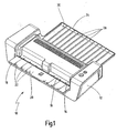
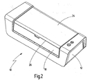
- the housing 12 has on the front side a front flap 18, which is located between a in Fig. 1 shown lamination and a in Fig. 2 shown closed position can be pivoted by 90 °.
- the lamination position In the lamination position ( Fig. 1 ) is an inner surface of the front flap 18 is arranged substantially flush with the flat surface 16 and serves as a support surface 20 for the Laminiergut.
- the support surface 20 is still extended by the flat surface 16 so that Laminiergut can be placed on it before lamination.
- wells 22 whose size is adapted to standard sizes of the Laminierguts. They are used for centering laminates, for example with sheet size DIN A4 or DIN A5 in front of the insertion slot 14. In the closed position ( Fig. 2 ) the front flap 18 closes the insertion slot 14.
- the housing 12 has a rear flap 24, which between an in Fig. 1 shown lamination and a in Fig. 2 shown Closed position is pivotable by 180 °.
- Both flaps 18, 24 are in the closed position ( Fig. 2 ), so they abut each other along a separating edge 26 in abutment.
- the rear flap 24 In the lamination position, the rear flap 24 extends in the extension of the flow channel. It is provided at the in the laminating up and in the closed position inwardly facing side with mutually parallel ribs 28, which together form a support surface 30 for ejected from the ejection slot laminate.
- the invention relates to a laminator 10 with a housing 12, with a recorded in the housing 12 lamination for laminating laminates of sheet material and plastic film into a laminate and with a flow channel for supplying the Laminierguts for laminating and for transporting the laminate of the laminating device, wherein the passage channel starts at an insertion slot 14 in the housing 12 and ends at an ejection slot in the housing 12.
- the housing 12 has a front flap 18, which is pivotable between a closed position in which it closes the insertion slot 14 and a laminating position in which it releases the insertion slot 14.
Landscapes
- Lining Or Joining Of Plastics Or The Like (AREA)
Description
- Die Erfindung betrifft ein Laminiergerät gemäß Oberbegriff des Anspruchs 1.
- Laminiergeräte dienen der Verbindung von Laminiergut, das in der Regel aus Papier und Kunststofffolie besteht, zu einem Laminat, bei dem das Papier in der Kunststofffolie aufgenommen und dicht verschweißt ist. Sie weisen eine Laminiervorrichtung mit beheizten Laminierwalzen auf, von denen mindestens eine motorisch angetrieben wird. Die Laminiervorrichtung ist in einem Gehäuse aufgenommen, das einen Einführschlitz für das Laminiergut und einen Auswurfschlitz für das Laminat aufweist. Zwischen dem Einführschlitz und dem Auswurfschlitz erstreckt sich ein Durchlaufkanal, den das Laminiergut bis zu den Laminierwalzen und das Laminat von den Laminierwalzen aus durchläuft. Beim Durchführen durch die Laminierwalzen wird das Laminiergut zum Laminat verschweißt. Durch den Einführschlitz kann neben dem Laminiergut allerdings auch Schmutz eindringen, der zum einen die Laminiervorrichtung verschmutzen und zu technischen Defekten führen kann. Zum anderen kann durch den Einführschlitz eingedrungener Schmutz vom Laminiergut mitgenommen und beim Laminieren zwischen den Laminierwalzen mit dem Laminiergut verschweißt werden. Ein solchermaßen verschmutztes Laminat ist unansehnlich.
- Die
JP 2005-343133 A - Es ist daher Aufgabe der Erfindung, ein Laminiergerät der eingangs genannten Art derart weiterzubilden, dass Verschmutzungen des Laminats besser vermieden werden können.
- Die Aufgabe wird erfindungsgemäß durch ein Laminiergerät mit den Merkmalen des Anspruchs 1 gelöst. Vorteilhafte Merkmale sind Gegenstand der abhängigen Ansprüche.
- Der Erfindung liegt der Gedanke zugrunde, dass der Einführschlitz mittels der Frontklappe auf einfache Weise verschlossen und freigegeben werden kann. Insbesondere dann, wenn das Laminiergerät nicht benutzt wird, kann die Frontklappe wie ein Deckel geschlossen werden, so dass das Eindringen von Schmutz durch den Einführschlitz zumindest erschwert wird.
- Gemäß einer vorteilhaften Weiterbildung weist die Frontklappe eine Auflagefläche für das Laminiergut auf, die sich in der Verlängerung des Durchlaufkanals befindet. Die Frontklappe dient dann nicht nur dem Verschluss des Einführschlitzes, sondern auch als Einführhilfe für das Laminiergut. Wenn das Laminiergut vor dem Einführen in den Einführschlitz bereits in eine Position gebracht wird, in der es sich in Richtung des Durchlaufkanals erstreckt, wird zudem das Risiko einer Fehlfunktion aufgrund falscher Handhabung verringert. Insbesondere wird bevorzugt, dass die Auflagefläche zumindest abschnittsweise mit einer Bodenfläche des Durchlaufkanals fluchtet, sofern eine solche vorhanden ist. Dadurch wird das Laminiergut in gerader Richtung eingezogen ohne geknickt oder gebogen zu werden.
- Zur weiteren Erleichterung des Einzugs des Laminierguts kann das Gehäuse eine weitere, sich vom Einführschlitz aus erstreckende Auflagefläche aufweisen, die mit der Auflagefläche der Frontklappe fluchtet. Die Frontklappe bildet mit ihrer Auflagefläche dann eine Verlängerung der weiteren Auflagefläche. Zweckmäßig ist die Frontklappe an ihrer Auflagefläche mit Vertiefungen als Positionierhilfen für Laminiergut unterschiedlicher normierter Größen versehen. Dabei kommen insbesondere die Standardgrößen für Papier wie DIN A4 bzw. DIN A5 in Betracht. Diese Maßnahme erleichtert die Positionierung des Laminierguts.
- Das Gehäuse weist eine Rückklappe auf, die zwischen einer Schließstellung, in der sie den Auswurfschlitz verschließt, und einer Laminierstellung, in der sie den Auswurfschlitz freigibt, verschwenkbar ist. Die Rückklappe kann somit das Eindringen von Schmutz in den Auswurfschlitz verhindern, wenn das Laminiergerät vorübergehend nicht in Betrieb ist. Zudem kann die Rückklappe eine Auflagefläche für das Laminat aufweisen. Dies ist insbesondere deshalb vorteilhaft, weil das Laminat direkt nach dem Austritt aus dem Auswurfschlitz noch warm ist. Fällt das Laminat dann vom Auswurfschlitz in eine undefinierte Position hinunter, kann es in gebogener Stellung liegen bleiben und so erkalten und die gebogene Stellung beibehalten. Dies wird dadurch verhindert, dass das Laminat auf eine Auflagefläche ausgeworfen wird, auf der es in definierter, flacher Position zu liegen kommt. Die Auflagefläche der Rückklappe wird vorteilhaft durch mehrere im Abstand zueinander angeordnete Auflageelemente gebildet. Das noch warme Laminat liegt dann nicht flächig auf der Auflagefläche auf, sondern nur stellenweise und kann dadurch schneller abkühlen.
- Die Frontklappe und die Rückklappe liegen in der Schließstellung entlang einer Trennkante aneinander an. Dies verleiht dem Laminiergerät eine kompakte Form und ein ansprechendes Design. Die Frontklappe und die Rückklappe können zudem Verbindungsmittel zum gegenseitigen Verbinden in der Schließstellung aufweisen. Dies können beispielsweise Magnete oder Rastverbindungen sein.
- Im Folgenden wird die Erfindung anhand eines in der Zeichnung in schematischer Weise dargestellten Ausführungsbeispiels näher erläutert. Es zeigen
- Fig. 1
- eine Laminiergerät mit der Frontklappe und der Rückklappe jeweils in der Laminierstellung; und
- Fig. 2
- das Laminiergerät gemäß
Fig. 1 mit der Frontklappe und der Rückklappe jeweils in der Schließstellung. - Das in
Fig. 1 undFig. 2 gezeigte Laminiergerät 10 weist ein Gehäuse 12 auf, in dem eine Laminiervorrichtung aufgenommen ist. Die Laminiervorrichtung, die hier nicht im Detail beschrieben werden soll, dient dem Laminieren von Laminiergut, wie Blattgut und Kunststofffolie unter Wärmeeinwirkung zu einem Laminat. Zum Einführen des Laminierguts weist das Gehäuse 12 einen Einführschlitz 14 an einer Vorderseite auf, zum Auswerfen des Laminats ist an der Rückseite ein Auswurfschlitz vorgesehen. Zwischen dem Einführschlitz 14 und dem Auswurfschlitz verläuft ein Durchlaufkanal, den das Laminiergut zu den Heißwalzen der Laminiervorrichtung und das Laminat von den Heißwalzen ausgehend durchläuft. - Vor dem Einführschlitz 14 weist das Gehäuse 12 einen Absatz auf, so dass sich vom Einführschlitz 14 aus eine ebene Fläche 16 erstreckt, die als Einführhilfe zum Einführen des Laminierguts in den Einführschlitz 14 dient. Die ebene Fläche 16 schließt sich unmittelbar an einen unteren Rand des Einführschlitzes 14 an und fluchtet mit diesem. Das Gehäuse 12 weist an der Vorderseite eine Frontklappe 18 auf, die zwischen einer in
Fig. 1 gezeigten Laminierstellung und einer inFig. 2 gezeigten Schließstellung um 90° verschwenkbar ist. In der Laminierstellung (Fig. 1 ) ist eine Innenfläche der Frontklappe 18 zur ebenen Fläche 16 im wesentlichen fluchtend angeordnet und dient als Auflagefläche 20 für das Laminiergut. Die Auflagefläche 20 wird durch die ebene Fläche 16 noch verlängert, so dass Laminiergut vor dem Laminieren auf sie aufgelegt werden kann. In der Auflagefläche 20 befinden sich Vertiefungen 22, deren Größe auf Standardgrößen des Laminierguts angepasst ist. Sie dienen dem Zentrieren von Laminiergut beispielsweise mit Blattgut der Größe DIN A4 oder DIN A5 vor dem Einführschlitz 14. In der Schließstellung (Fig. 2 ) verschließt die Frontklappe 18 den Einführschlitz 14. - An der Rückseite weist das Gehäuse 12 eine Rückklappe 24 auf, die zwischen einer in
Fig. 1 gezeigten Laminierstellung und einer inFig. 2 gezeigten Schließstellung um 180° verschwenkbar ist. Befinden sich beide Klappen 18, 24 in der Schließstellung (Fig. 2 ), so liegen sie entlang einer Trennkante 26 auf Stoß aneinander an. Es sind zudem in beiden Klappen 18, 24 Magnete angeordnet, die sie in der Schließstellung an der jeweils anderen Klappe festhalten. Befinden sich beide Klappen 18, 24 in der Schließstellung, so verleihen sie dem Laminiergerät 10 ein kompaktes, ansprechendes Design. - In der Laminierstellung erstreckt sich die Rückklappe 24 in der Verlängerung des Durchlaufkanals. Sie ist an der in der Laminierstellung nach oben und in der Schließstellung nach innen weisenden Seite mit parallel zueinander verlaufenden Rippen 28 versehen, die zusammen eine Auflagefläche 30 für das aus dem Auswurfschlitz ausgeworfene Laminat bilden.
- Zusammenfassend ist folgendes festzuhalten: Die Erfindung betrifft ein Laminiergerät 10 mit einem Gehäuse 12, mit einer im Gehäuse 12 aufgenommenen Laminiervorrichtung zur Laminierung von Laminiergut aus Blattgut und Kunststofffolie zu einem Laminat und mit einem Durchlaufkanal zur Zuführung des Laminierguts zur Laminiervorrichtung und zum Abtransport des Laminats von der Laminiervorrichtung, wobei der Durchlaufkanal an einem Einführschlitz 14 im Gehäuse 12 beginnt und an einem Auswurfschlitz im Gehäuse 12 endet. Erfindungsgemäß ist vorgesehen, dass das Gehäuse 12 eine Frontklappe 18 aufweist, die zwischen einer Schließstellung, in der sie den Einführschlitz 14 verschließt, und einer Laminierstellung, in der sie den Einführschlitz 14 freigibt, verschwenkbar ist.
Claims (8)
- Laminiergerät mit einem Gehäuse (12), mit einer im Gehäuse (12) aufgenommenen Laminiervorrichtung zur Laminierung von Laminiergut aus Blattgut und Kunststofffolie zu einem Laminat und mit einem Durchlaufkanal zur Zuführung des Laminierguts zur Laminiervorrichtung und zum Abtransport des Laminats von der Laminiervorrichtung, wobei der Durchlaufkanal an einem Einführschlitz (14) im Gehäuse (12) beginnt und an einem Auswun`schlitz im Gehäuse (12) endet, wobei das Gehäuse (12) eine Frontklappe (18) aufweist, die zwischen einer Schließstellung, in der sie den Einführschlitz (14) verschließt, und einer Laminierstellung, in der sie den Einführschlitz (14) freigibt, verschwenkbar ist, und wobei das Gehäuse (12) eine Rückklappe (24) aufweist, die zwischen einer Schließstellung, in der sie den Auswurfschlitz verschließt, und einer Laminierstellung, in der sie den Auswurfschlitz freigibt, verschwenkbar ist, dadurch gekennzeichnet, dass die Frontklappe (18) und die Rückklappe (24) in der Schließstellung entlang einer Trennkante (26) aneinander anliegen.
- Laminiergerät nach Anspruch 1, dadurch gekennzeichnet, dass die Frontklappe (18) und die Rückklappe (24) in der Schließstellung entlang der Trennkante (26) auf Stoß aneinander anliegen.
- Laminiergerät nach Anspruch 1 oder 2, dadurch gekennzeichnet, dass die Frontklappe (18) und die Rückklappe (24) Verbindungsmittel zum gegenseitigen Verbinden in der Schließstellung aufweisen.
- Laminiergerät nach einem der vorangehenden Ansprüche, dadurch gekennzeichnet, dass die Frontklappe (18) eine Auflagefläche (20) für das Laminiergut aufweist, die sich in der Verlängerung des Durchlaufkanals befindet und vorzugsweise zumindest abschnittsweise mit einer Bodenfläche des Durchlaufkanals fluchtet.
- Laminiergerät nach Anspruch 4, dadurch gekennzeichnet, dass das Gehäuse (12) eine weitere, sich vom Einführschlitz (14) aus erstreckende Auflagefläche (16) aufweist, die mit der Auflagefläche (20) der Frontklappe (18) fluchtet.
- Laminiergerät nach Anspruch 4 oder 5, dadurch gekennzeichnet, dass die Frontklappe (18) an ihrer Auflagefläche (20) mit Vertiefungen (22) als Positionierhilfen für Laminiergut unterschiedlicher normierter Größen versehen ist.
- Laminiergerät nach einem der vorangehenden Ansprüche, dadurch gekennzeichnet, dass die Rückklappe (24) eine Auflagefläche (30) für das Laminat aufweist.
- Laminiergerät nach Anspruch 7, dadurch gekennzeichnet, dass die Auflagefläche (30) der Rückklappe (24) durch mehrere im Abstand zueinander angeordnete Auflageelemente (28) gebildet wird.
Applications Claiming Priority (1)
| Application Number | Priority Date | Filing Date | Title |
|---|---|---|---|
| DE102010033422A DE102010033422A1 (de) | 2010-08-04 | 2010-08-04 | Laminiergerät |
Publications (2)
| Publication Number | Publication Date |
|---|---|
| EP2415600A1 EP2415600A1 (de) | 2012-02-08 |
| EP2415600B1 true EP2415600B1 (de) | 2013-09-11 |
Family
ID=44653131
Family Applications (1)
| Application Number | Title | Priority Date | Filing Date |
|---|---|---|---|
| EP11173388.7A Active EP2415600B1 (de) | 2010-08-04 | 2011-07-11 | Kompaktes Laminiergerät |
Country Status (2)
| Country | Link |
|---|---|
| EP (1) | EP2415600B1 (de) |
| DE (1) | DE102010033422A1 (de) |
Families Citing this family (1)
| Publication number | Priority date | Publication date | Assignee | Title |
|---|---|---|---|---|
| DE102016004615A1 (de) | 2016-04-19 | 2017-10-19 | Esselte Leitz Gmbh & Co. Kg | Laminiergerät |
Family Cites Families (8)
| Publication number | Priority date | Publication date | Assignee | Title |
|---|---|---|---|---|
| US6698487B2 (en) * | 2000-11-15 | 2004-03-02 | Xyron, Inc. | Master processing apparatus |
| US6672354B2 (en) * | 2001-07-13 | 2004-01-06 | Xyron, Inc. | Gauge assembly for a master processing apparatus |
| US6675854B2 (en) * | 2002-05-08 | 2004-01-13 | Xyron, Inc. | Guide structure for a master processing apparatus |
| US6779578B2 (en) * | 2002-06-25 | 2004-08-24 | Xyron, Inc. | Master processing apparatus with ejector mechanism |
| US7022203B2 (en) * | 2003-11-07 | 2006-04-04 | Henkel Consumer Adhesives, Inc. | Electric laminator |
| JP2005343133A (ja) * | 2004-06-07 | 2005-12-15 | Asuka:Kk | ラミネータ |
| GB2467856B8 (en) * | 2005-01-03 | 2010-10-06 | Fellowes Inc | Portable laminator. |
| GB2443175B (en) * | 2006-10-24 | 2011-07-20 | Acco Uk Ltd | A laminator assembly |
-
2010
- 2010-08-04 DE DE102010033422A patent/DE102010033422A1/de not_active Ceased
-
2011
- 2011-07-11 EP EP11173388.7A patent/EP2415600B1/de active Active
Also Published As
| Publication number | Publication date |
|---|---|
| DE102010033422A1 (de) | 2012-02-09 |
| EP2415600A1 (de) | 2012-02-08 |
Similar Documents
| Publication | Publication Date | Title |
|---|---|---|
| EP3017940B2 (de) | Verfahren und eine Vorrichtung zur Herstellung von Säcken aus schlauchförmigen Sackkörpern | |
| EP3150524A1 (de) | Splicevorrichtung | |
| EP3045414B1 (de) | Verfahren und vorrichtung zum zusammenführen eines umschlags mit mehreren beilagen zu einer werbemittelzusammenstellung | |
| DE102010053199B4 (de) | Vorrichtung zur Bearbeitung einer fortlaufenden Materialbahn | |
| DE112006002932T5 (de) | Separator für eine Brennstoffzelle und Verfahren und Vorrichtung zum Fördern des Separators | |
| EP2409938A2 (de) | Unterdruckfördereinrichtung | |
| EP2921294B1 (de) | Vorrichtung zur Herstellung einer mindestens einseitig kaschierten endlosen Wellpappe-Bahn | |
| EP3365146A1 (de) | Vorrichtung und verfahren zum abtrennen und bereitstellen einer folienteilstückeinheit von einem lebensmittelverpackungsfolienband | |
| EP2415600A1 (de) | Kompaktes Laminiergerät | |
| EP2455227A1 (de) | Umschlaganlegevorrichtung | |
| DE102022105713A1 (de) | Vorrichtung und Verfahren zur Herstellung von Verpackungsbehältnissen | |
| EP1213245B1 (de) | Verfahren und Vorrichtung zum Falzen von Bögen | |
| EP2727856A2 (de) | Isolierbecher und Verfahren zum Herstellen eines Isolierbechers | |
| WO2018069371A1 (de) | Verfahren zur herrichtung von strangmaterial für die verarbeitung zu dichtungen | |
| DE202005005020U1 (de) | Laminiergerät | |
| EP3235639B1 (de) | Laminiergerät | |
| DE102018103889A1 (de) | Zusammenschluss von Lösungsbeuteln für die Dialyse und Verfahren zu deren Befüllung | |
| DE102013001778A1 (de) | Überwachungsverfahren zur Kollisionsvermeidung einer Stanzmaschine mit Bremsbürste | |
| DE102013001684A1 (de) | Vorrichtung zum Aufbringen von Hinterklebematerial in der Druckweiterverarbeitung | |
| DE2908943A1 (de) | Vorrichtung zum einbringen eines losen flachstapels in einen verpackungskarton | |
| DE102006031983B3 (de) | Falztasche, Falzmaschine und Verfahren | |
| EP2886361B1 (de) | Vorrichtung und Verfahren zur Herstellung von Tischkalendern | |
| DE102019125352B4 (de) | Bahnversetzeinrichtung für Etiketten-Druckmaschinen und Etiketten-Verarbeitungsmaschinen | |
| EP2514593A1 (de) | Einführhilfe | |
| DE202018101469U1 (de) | Tiefziehverpackungsmaschine mit Folienumlenkung |
Legal Events
| Date | Code | Title | Description |
|---|---|---|---|
| AK | Designated contracting states |
Kind code of ref document: A1 Designated state(s): AL AT BE BG CH CY CZ DE DK EE ES FI FR GB GR HR HU IE IS IT LI LT LU LV MC MK MT NL NO PL PT RO RS SE SI SK SM TR |
|
| AX | Request for extension of the european patent |
Extension state: BA ME |
|
| PUAI | Public reference made under article 153(3) epc to a published international application that has entered the european phase |
Free format text: ORIGINAL CODE: 0009012 |
|
| 17P | Request for examination filed |
Effective date: 20120717 |
|
| R17P | Request for examination filed (corrected) |
Effective date: 20120717 |
|
| GRAP | Despatch of communication of intention to grant a patent |
Free format text: ORIGINAL CODE: EPIDOSNIGR1 |
|
| RIC1 | Information provided on ipc code assigned before grant |
Ipc: B32B 37/18 20060101AFI20130213BHEP Ipc: B32B 37/14 20060101ALI20130213BHEP Ipc: B32B 37/08 20060101ALN20130213BHEP |
|
| GRAS | Grant fee paid |
Free format text: ORIGINAL CODE: EPIDOSNIGR3 |
|
| GRAA | (expected) grant |
Free format text: ORIGINAL CODE: 0009210 |
|
| AK | Designated contracting states |
Kind code of ref document: B1 Designated state(s): AL AT BE BG CH CY CZ DE DK EE ES FI FR GB GR HR HU IE IS IT LI LT LU LV MC MK MT NL NO PL PT RO RS SE SI SK SM TR |
|
| REG | Reference to a national code |
Ref country code: GB Ref legal event code: FG4D Free format text: NOT ENGLISH |
|
| REG | Reference to a national code |
Ref country code: CH Ref legal event code: EP |
|
| REG | Reference to a national code |
Ref country code: AT Ref legal event code: REF Ref document number: 631379 Country of ref document: AT Kind code of ref document: T Effective date: 20130915 |
|
| REG | Reference to a national code |
Ref country code: IE Ref legal event code: FG4D Free format text: LANGUAGE OF EP DOCUMENT: GERMAN |
|
| REG | Reference to a national code |
Ref country code: DE Ref legal event code: R096 Ref document number: 502011001318 Country of ref document: DE Effective date: 20131107 |
|
| REG | Reference to a national code |
Ref country code: NL Ref legal event code: T3 |
|
| PG25 | Lapsed in a contracting state [announced via postgrant information from national office to epo] |
Ref country code: SE Free format text: LAPSE BECAUSE OF FAILURE TO SUBMIT A TRANSLATION OF THE DESCRIPTION OR TO PAY THE FEE WITHIN THE PRESCRIBED TIME-LIMIT Effective date: 20130911 Ref country code: NO Free format text: LAPSE BECAUSE OF FAILURE TO SUBMIT A TRANSLATION OF THE DESCRIPTION OR TO PAY THE FEE WITHIN THE PRESCRIBED TIME-LIMIT Effective date: 20131211 Ref country code: LT Free format text: LAPSE BECAUSE OF FAILURE TO SUBMIT A TRANSLATION OF THE DESCRIPTION OR TO PAY THE FEE WITHIN THE PRESCRIBED TIME-LIMIT Effective date: 20130911 Ref country code: HR Free format text: LAPSE BECAUSE OF FAILURE TO SUBMIT A TRANSLATION OF THE DESCRIPTION OR TO PAY THE FEE WITHIN THE PRESCRIBED TIME-LIMIT Effective date: 20130911 Ref country code: CY Free format text: LAPSE BECAUSE OF FAILURE TO SUBMIT A TRANSLATION OF THE DESCRIPTION OR TO PAY THE FEE WITHIN THE PRESCRIBED TIME-LIMIT Effective date: 20130807 |
|
| REG | Reference to a national code |
Ref country code: LT Ref legal event code: MG4D |
|
| PG25 | Lapsed in a contracting state [announced via postgrant information from national office to epo] |
Ref country code: LV Free format text: LAPSE BECAUSE OF FAILURE TO SUBMIT A TRANSLATION OF THE DESCRIPTION OR TO PAY THE FEE WITHIN THE PRESCRIBED TIME-LIMIT Effective date: 20130911 Ref country code: SI Free format text: LAPSE BECAUSE OF FAILURE TO SUBMIT A TRANSLATION OF THE DESCRIPTION OR TO PAY THE FEE WITHIN THE PRESCRIBED TIME-LIMIT Effective date: 20130911 Ref country code: GR Free format text: LAPSE BECAUSE OF FAILURE TO SUBMIT A TRANSLATION OF THE DESCRIPTION OR TO PAY THE FEE WITHIN THE PRESCRIBED TIME-LIMIT Effective date: 20131212 Ref country code: FI Free format text: LAPSE BECAUSE OF FAILURE TO SUBMIT A TRANSLATION OF THE DESCRIPTION OR TO PAY THE FEE WITHIN THE PRESCRIBED TIME-LIMIT Effective date: 20130911 |
|
| PG25 | Lapsed in a contracting state [announced via postgrant information from national office to epo] |
Ref country code: CY Free format text: LAPSE BECAUSE OF FAILURE TO SUBMIT A TRANSLATION OF THE DESCRIPTION OR TO PAY THE FEE WITHIN THE PRESCRIBED TIME-LIMIT Effective date: 20130911 |
|
| PG25 | Lapsed in a contracting state [announced via postgrant information from national office to epo] |
Ref country code: IS Free format text: LAPSE BECAUSE OF FAILURE TO SUBMIT A TRANSLATION OF THE DESCRIPTION OR TO PAY THE FEE WITHIN THE PRESCRIBED TIME-LIMIT Effective date: 20140111 Ref country code: SK Free format text: LAPSE BECAUSE OF FAILURE TO SUBMIT A TRANSLATION OF THE DESCRIPTION OR TO PAY THE FEE WITHIN THE PRESCRIBED TIME-LIMIT Effective date: 20130911 Ref country code: RO Free format text: LAPSE BECAUSE OF FAILURE TO SUBMIT A TRANSLATION OF THE DESCRIPTION OR TO PAY THE FEE WITHIN THE PRESCRIBED TIME-LIMIT Effective date: 20130911 Ref country code: EE Free format text: LAPSE BECAUSE OF FAILURE TO SUBMIT A TRANSLATION OF THE DESCRIPTION OR TO PAY THE FEE WITHIN THE PRESCRIBED TIME-LIMIT Effective date: 20130911 Ref country code: CZ Free format text: LAPSE BECAUSE OF FAILURE TO SUBMIT A TRANSLATION OF THE DESCRIPTION OR TO PAY THE FEE WITHIN THE PRESCRIBED TIME-LIMIT Effective date: 20130911 |
|
| PG25 | Lapsed in a contracting state [announced via postgrant information from national office to epo] |
Ref country code: ES Free format text: LAPSE BECAUSE OF FAILURE TO SUBMIT A TRANSLATION OF THE DESCRIPTION OR TO PAY THE FEE WITHIN THE PRESCRIBED TIME-LIMIT Effective date: 20130911 Ref country code: PL Free format text: LAPSE BECAUSE OF FAILURE TO SUBMIT A TRANSLATION OF THE DESCRIPTION OR TO PAY THE FEE WITHIN THE PRESCRIBED TIME-LIMIT Effective date: 20130911 |
|
| REG | Reference to a national code |
Ref country code: DE Ref legal event code: R097 Ref document number: 502011001318 Country of ref document: DE |
|
| PG25 | Lapsed in a contracting state [announced via postgrant information from national office to epo] |
Ref country code: PT Free format text: LAPSE BECAUSE OF FAILURE TO SUBMIT A TRANSLATION OF THE DESCRIPTION OR TO PAY THE FEE WITHIN THE PRESCRIBED TIME-LIMIT Effective date: 20140113 |
|
| PLBE | No opposition filed within time limit |
Free format text: ORIGINAL CODE: 0009261 |
|
| STAA | Information on the status of an ep patent application or granted ep patent |
Free format text: STATUS: NO OPPOSITION FILED WITHIN TIME LIMIT |
|
| 26N | No opposition filed |
Effective date: 20140612 |
|
| PG25 | Lapsed in a contracting state [announced via postgrant information from national office to epo] |
Ref country code: IT Free format text: LAPSE BECAUSE OF FAILURE TO SUBMIT A TRANSLATION OF THE DESCRIPTION OR TO PAY THE FEE WITHIN THE PRESCRIBED TIME-LIMIT Effective date: 20130911 |
|
| REG | Reference to a national code |
Ref country code: DE Ref legal event code: R097 Ref document number: 502011001318 Country of ref document: DE Effective date: 20140612 |
|
| PG25 | Lapsed in a contracting state [announced via postgrant information from national office to epo] |
Ref country code: DK Free format text: LAPSE BECAUSE OF FAILURE TO SUBMIT A TRANSLATION OF THE DESCRIPTION OR TO PAY THE FEE WITHIN THE PRESCRIBED TIME-LIMIT Effective date: 20130911 |
|
| REG | Reference to a national code |
Ref country code: DE Ref legal event code: R082 Ref document number: 502011001318 Country of ref document: DE Representative=s name: PATENTANWAELTE BREGENZER UND REULE PARTNERSCHA, DE |
|
| PG25 | Lapsed in a contracting state [announced via postgrant information from national office to epo] |
Ref country code: LU Free format text: LAPSE BECAUSE OF FAILURE TO SUBMIT A TRANSLATION OF THE DESCRIPTION OR TO PAY THE FEE WITHIN THE PRESCRIBED TIME-LIMIT Effective date: 20140711 |
|
| REG | Reference to a national code |
Ref country code: CH Ref legal event code: PL |
|
| REG | Reference to a national code |
Ref country code: FR Ref legal event code: GC Effective date: 20150310 |
|
| REG | Reference to a national code |
Ref country code: IE Ref legal event code: MM4A |
|
| PG25 | Lapsed in a contracting state [announced via postgrant information from national office to epo] |
Ref country code: CH Free format text: LAPSE BECAUSE OF NON-PAYMENT OF DUE FEES Effective date: 20140731 Ref country code: LI Free format text: LAPSE BECAUSE OF NON-PAYMENT OF DUE FEES Effective date: 20140731 |
|
| PG25 | Lapsed in a contracting state [announced via postgrant information from national office to epo] |
Ref country code: IE Free format text: LAPSE BECAUSE OF NON-PAYMENT OF DUE FEES Effective date: 20140711 |
|
| PG25 | Lapsed in a contracting state [announced via postgrant information from national office to epo] |
Ref country code: MC Free format text: LAPSE BECAUSE OF FAILURE TO SUBMIT A TRANSLATION OF THE DESCRIPTION OR TO PAY THE FEE WITHIN THE PRESCRIBED TIME-LIMIT Effective date: 20130911 Ref country code: SM Free format text: LAPSE BECAUSE OF FAILURE TO SUBMIT A TRANSLATION OF THE DESCRIPTION OR TO PAY THE FEE WITHIN THE PRESCRIBED TIME-LIMIT Effective date: 20130911 |
|
| PG25 | Lapsed in a contracting state [announced via postgrant information from national office to epo] |
Ref country code: RS Free format text: LAPSE BECAUSE OF FAILURE TO SUBMIT A TRANSLATION OF THE DESCRIPTION OR TO PAY THE FEE WITHIN THE PRESCRIBED TIME-LIMIT Effective date: 20130911 Ref country code: BG Free format text: LAPSE BECAUSE OF FAILURE TO SUBMIT A TRANSLATION OF THE DESCRIPTION OR TO PAY THE FEE WITHIN THE PRESCRIBED TIME-LIMIT Effective date: 20130911 Ref country code: MT Free format text: LAPSE BECAUSE OF FAILURE TO SUBMIT A TRANSLATION OF THE DESCRIPTION OR TO PAY THE FEE WITHIN THE PRESCRIBED TIME-LIMIT Effective date: 20130911 |
|
| REG | Reference to a national code |
Ref country code: FR Ref legal event code: PLFP Year of fee payment: 6 |
|
| PG25 | Lapsed in a contracting state [announced via postgrant information from national office to epo] |
Ref country code: HU Free format text: LAPSE BECAUSE OF FAILURE TO SUBMIT A TRANSLATION OF THE DESCRIPTION OR TO PAY THE FEE WITHIN THE PRESCRIBED TIME-LIMIT; INVALID AB INITIO Effective date: 20110711 Ref country code: TR Free format text: LAPSE BECAUSE OF FAILURE TO SUBMIT A TRANSLATION OF THE DESCRIPTION OR TO PAY THE FEE WITHIN THE PRESCRIBED TIME-LIMIT Effective date: 20130911 |
|
| REG | Reference to a national code |
Ref country code: FR Ref legal event code: PLFP Year of fee payment: 7 |
|
| REG | Reference to a national code |
Ref country code: FR Ref legal event code: RG Effective date: 20170726 |
|
| REG | Reference to a national code |
Ref country code: AT Ref legal event code: MM01 Ref document number: 631379 Country of ref document: AT Kind code of ref document: T Effective date: 20160711 |
|
| PG25 | Lapsed in a contracting state [announced via postgrant information from national office to epo] |
Ref country code: AT Free format text: LAPSE BECAUSE OF NON-PAYMENT OF DUE FEES Effective date: 20160711 |
|
| REG | Reference to a national code |
Ref country code: DE Ref legal event code: R082 Ref document number: 502011001318 Country of ref document: DE Representative=s name: PATENTANWAELTE BREGENZER UND REULE PARTNERSCHA, DE Ref country code: DE Ref legal event code: R081 Ref document number: 502011001318 Country of ref document: DE Owner name: LEITZ ACCO BRANDS GMBH & CO KG, DE Free format text: FORMER OWNER: ESSELTE LEITZ GMBH & CO. KG, 70469 STUTTGART, DE |
|
| PG25 | Lapsed in a contracting state [announced via postgrant information from national office to epo] |
Ref country code: MK Free format text: LAPSE BECAUSE OF FAILURE TO SUBMIT A TRANSLATION OF THE DESCRIPTION OR TO PAY THE FEE WITHIN THE PRESCRIBED TIME-LIMIT Effective date: 20130911 |
|
| REG | Reference to a national code |
Ref country code: FR Ref legal event code: PLFP Year of fee payment: 8 |
|
| REG | Reference to a national code |
Ref country code: NL Ref legal event code: HC Owner name: LEITZ ACCO BRANDS GMBH & CO KG; DE Free format text: DETAILS ASSIGNMENT: CHANGE OF OWNER(S), CHANGE OF OWNER(S) NAME; FORMER OWNER NAME: ESSELTE LEITZ GMBH & CO. KG Effective date: 20180814 |
|
| PG25 | Lapsed in a contracting state [announced via postgrant information from national office to epo] |
Ref country code: AL Free format text: LAPSE BECAUSE OF FAILURE TO SUBMIT A TRANSLATION OF THE DESCRIPTION OR TO PAY THE FEE WITHIN THE PRESCRIBED TIME-LIMIT Effective date: 20130911 |
|
| PGFP | Annual fee paid to national office [announced via postgrant information from national office to epo] |
Ref country code: BE Payment date: 20180718 Year of fee payment: 8 |
|
| REG | Reference to a national code |
Ref country code: BE Ref legal event code: HC Owner name: LEITZ ACCO BRANDS GMBH & CO KG; DE Free format text: DETAILS ASSIGNMENT: CHANGE OF OWNER(S), CHANGEMENT DE NOM DU PROPRIETAIRE; FORMER OWNER NAME: ESSELTE LEITZ GMBH & CO. KG Effective date: 20181015 |
|
| REG | Reference to a national code |
Ref country code: BE Ref legal event code: MM Effective date: 20190731 |
|
| PG25 | Lapsed in a contracting state [announced via postgrant information from national office to epo] |
Ref country code: NL Free format text: LAPSE BECAUSE OF NON-PAYMENT OF DUE FEES Effective date: 20190801 |
|
| REG | Reference to a national code |
Ref country code: NL Ref legal event code: MM Effective date: 20190801 |
|
| PG25 | Lapsed in a contracting state [announced via postgrant information from national office to epo] |
Ref country code: BE Free format text: LAPSE BECAUSE OF NON-PAYMENT OF DUE FEES Effective date: 20190731 |
|
| P01 | Opt-out of the competence of the unified patent court (upc) registered |
Effective date: 20230524 |
|
| PGFP | Annual fee paid to national office [announced via postgrant information from national office to epo] |
Ref country code: DE Payment date: 20250409 Year of fee payment: 15 |
|
| PGFP | Annual fee paid to national office [announced via postgrant information from national office to epo] |
Ref country code: GB Payment date: 20250722 Year of fee payment: 15 |
|
| PGFP | Annual fee paid to national office [announced via postgrant information from national office to epo] |
Ref country code: FR Payment date: 20250725 Year of fee payment: 15 |