EP2414672B1 - Procédé et appareil permettant d'extraire de l'énergie d'un flux d'énergie variable issu d'une source d'énergie renouvelable - Google Patents
Procédé et appareil permettant d'extraire de l'énergie d'un flux d'énergie variable issu d'une source d'énergie renouvelable Download PDFInfo
- Publication number
- EP2414672B1 EP2414672B1 EP11729387.8A EP11729387A EP2414672B1 EP 2414672 B1 EP2414672 B1 EP 2414672B1 EP 11729387 A EP11729387 A EP 11729387A EP 2414672 B1 EP2414672 B1 EP 2414672B1
- Authority
- EP
- European Patent Office
- Prior art keywords
- pressure
- range
- energy
- fluid
- displacement
- Prior art date
- Legal status (The legal status is an assumption and is not a legal conclusion. Google has not performed a legal analysis and makes no representation as to the accuracy of the status listed.)
- Not-in-force
Links
- 238000000034 method Methods 0.000 title claims description 33
- 239000012530 fluid Substances 0.000 claims description 196
- 238000006073 displacement reaction Methods 0.000 claims description 98
- 238000000605 extraction Methods 0.000 claims description 26
- 230000001105 regulatory effect Effects 0.000 claims description 21
- 230000008859 change Effects 0.000 claims description 17
- 238000009499 grossing Methods 0.000 claims description 14
- 238000004891 communication Methods 0.000 claims description 12
- 238000004364 calculation method Methods 0.000 claims description 8
- 230000033228 biological regulation Effects 0.000 claims description 5
- 230000006835 compression Effects 0.000 claims description 4
- 238000007906 compression Methods 0.000 claims description 4
- 230000009471 action Effects 0.000 claims description 3
- 230000000694 effects Effects 0.000 claims description 3
- 230000001419 dependent effect Effects 0.000 claims description 2
- 230000006870 function Effects 0.000 description 75
- 239000011295 pitch Substances 0.000 description 17
- 238000004422 calculation algorithm Methods 0.000 description 12
- 230000005611 electricity Effects 0.000 description 12
- 238000012935 Averaging Methods 0.000 description 8
- 230000008901 benefit Effects 0.000 description 7
- 238000012937 correction Methods 0.000 description 7
- 230000001133 acceleration Effects 0.000 description 6
- 230000005540 biological transmission Effects 0.000 description 6
- 230000008602 contraction Effects 0.000 description 4
- 230000001276 controlling effect Effects 0.000 description 4
- 230000002706 hydrostatic effect Effects 0.000 description 4
- 238000013461 design Methods 0.000 description 3
- 230000007246 mechanism Effects 0.000 description 3
- 238000005086 pumping Methods 0.000 description 3
- 230000009467 reduction Effects 0.000 description 3
- IJGRMHOSHXDMSA-UHFFFAOYSA-N Atomic nitrogen Chemical compound N#N IJGRMHOSHXDMSA-UHFFFAOYSA-N 0.000 description 2
- 238000004146 energy storage Methods 0.000 description 2
- 230000002349 favourable effect Effects 0.000 description 2
- 238000005259 measurement Methods 0.000 description 2
- 230000008569 process Effects 0.000 description 2
- 230000004044 response Effects 0.000 description 2
- 230000000717 retained effect Effects 0.000 description 2
- 238000007789 sealing Methods 0.000 description 2
- 230000001360 synchronised effect Effects 0.000 description 2
- 238000012546 transfer Methods 0.000 description 2
- XLYOFNOQVPJJNP-UHFFFAOYSA-N water Substances O XLYOFNOQVPJJNP-UHFFFAOYSA-N 0.000 description 2
- 229910000831 Steel Inorganic materials 0.000 description 1
- 230000004913 activation Effects 0.000 description 1
- 238000001994 activation Methods 0.000 description 1
- 238000013459 approach Methods 0.000 description 1
- 238000006243 chemical reaction Methods 0.000 description 1
- 238000011217 control strategy Methods 0.000 description 1
- 238000001514 detection method Methods 0.000 description 1
- 238000010586 diagram Methods 0.000 description 1
- 230000003203 everyday effect Effects 0.000 description 1
- 238000002474 experimental method Methods 0.000 description 1
- 238000001914 filtration Methods 0.000 description 1
- 239000007789 gas Substances 0.000 description 1
- 239000010720 hydraulic oil Substances 0.000 description 1
- 238000009434 installation Methods 0.000 description 1
- 238000012886 linear function Methods 0.000 description 1
- 239000000203 mixture Substances 0.000 description 1
- 238000012986 modification Methods 0.000 description 1
- 230000004048 modification Effects 0.000 description 1
- 229910052757 nitrogen Inorganic materials 0.000 description 1
- 238000012887 quadratic function Methods 0.000 description 1
- 230000008439 repair process Effects 0.000 description 1
- 239000004065 semiconductor Substances 0.000 description 1
- 238000004088 simulation Methods 0.000 description 1
- 238000009987 spinning Methods 0.000 description 1
- 239000010959 steel Substances 0.000 description 1
Images


Classifications
-
- F—MECHANICAL ENGINEERING; LIGHTING; HEATING; WEAPONS; BLASTING
- F16—ENGINEERING ELEMENTS AND UNITS; GENERAL MEASURES FOR PRODUCING AND MAINTAINING EFFECTIVE FUNCTIONING OF MACHINES OR INSTALLATIONS; THERMAL INSULATION IN GENERAL
- F16H—GEARING
- F16H61/00—Control functions within control units of change-speed- or reversing-gearings for conveying rotary motion ; Control of exclusively fluid gearing, friction gearing, gearings with endless flexible members or other particular types of gearing
- F16H61/38—Control of exclusively fluid gearing
- F16H61/40—Control of exclusively fluid gearing hydrostatic
- F16H61/4035—Control of circuit flow
-
- F—MECHANICAL ENGINEERING; LIGHTING; HEATING; WEAPONS; BLASTING
- F03—MACHINES OR ENGINES FOR LIQUIDS; WIND, SPRING, OR WEIGHT MOTORS; PRODUCING MECHANICAL POWER OR A REACTIVE PROPULSIVE THRUST, NOT OTHERWISE PROVIDED FOR
- F03D—WIND MOTORS
- F03D9/00—Adaptations of wind motors for special use; Combinations of wind motors with apparatus driven thereby; Wind motors specially adapted for installation in particular locations
- F03D9/20—Wind motors characterised by the driven apparatus
- F03D9/28—Wind motors characterised by the driven apparatus the apparatus being a pump or a compressor
-
- F—MECHANICAL ENGINEERING; LIGHTING; HEATING; WEAPONS; BLASTING
- F03—MACHINES OR ENGINES FOR LIQUIDS; WIND, SPRING, OR WEIGHT MOTORS; PRODUCING MECHANICAL POWER OR A REACTIVE PROPULSIVE THRUST, NOT OTHERWISE PROVIDED FOR
- F03D—WIND MOTORS
- F03D15/00—Transmission of mechanical power
-
- F—MECHANICAL ENGINEERING; LIGHTING; HEATING; WEAPONS; BLASTING
- F03—MACHINES OR ENGINES FOR LIQUIDS; WIND, SPRING, OR WEIGHT MOTORS; PRODUCING MECHANICAL POWER OR A REACTIVE PROPULSIVE THRUST, NOT OTHERWISE PROVIDED FOR
- F03D—WIND MOTORS
- F03D15/00—Transmission of mechanical power
- F03D15/10—Transmission of mechanical power using gearing not limited to rotary motion, e.g. with oscillating or reciprocating members
- F03D15/15—Changing or adjusting stroke
-
- F—MECHANICAL ENGINEERING; LIGHTING; HEATING; WEAPONS; BLASTING
- F03—MACHINES OR ENGINES FOR LIQUIDS; WIND, SPRING, OR WEIGHT MOTORS; PRODUCING MECHANICAL POWER OR A REACTIVE PROPULSIVE THRUST, NOT OTHERWISE PROVIDED FOR
- F03D—WIND MOTORS
- F03D7/00—Controlling wind motors
- F03D7/02—Controlling wind motors the wind motors having rotation axis substantially parallel to the air flow entering the rotor
-
- F—MECHANICAL ENGINEERING; LIGHTING; HEATING; WEAPONS; BLASTING
- F03—MACHINES OR ENGINES FOR LIQUIDS; WIND, SPRING, OR WEIGHT MOTORS; PRODUCING MECHANICAL POWER OR A REACTIVE PROPULSIVE THRUST, NOT OTHERWISE PROVIDED FOR
- F03D—WIND MOTORS
- F03D9/00—Adaptations of wind motors for special use; Combinations of wind motors with apparatus driven thereby; Wind motors specially adapted for installation in particular locations
- F03D9/20—Wind motors characterised by the driven apparatus
- F03D9/25—Wind motors characterised by the driven apparatus the apparatus being an electrical generator
-
- F—MECHANICAL ENGINEERING; LIGHTING; HEATING; WEAPONS; BLASTING
- F16—ENGINEERING ELEMENTS AND UNITS; GENERAL MEASURES FOR PRODUCING AND MAINTAINING EFFECTIVE FUNCTIONING OF MACHINES OR INSTALLATIONS; THERMAL INSULATION IN GENERAL
- F16H—GEARING
- F16H61/00—Control functions within control units of change-speed- or reversing-gearings for conveying rotary motion ; Control of exclusively fluid gearing, friction gearing, gearings with endless flexible members or other particular types of gearing
- F16H61/38—Control of exclusively fluid gearing
- F16H61/40—Control of exclusively fluid gearing hydrostatic
- F16H61/4148—Open loop circuits
-
- F—MECHANICAL ENGINEERING; LIGHTING; HEATING; WEAPONS; BLASTING
- F16—ENGINEERING ELEMENTS AND UNITS; GENERAL MEASURES FOR PRODUCING AND MAINTAINING EFFECTIVE FUNCTIONING OF MACHINES OR INSTALLATIONS; THERMAL INSULATION IN GENERAL
- F16H—GEARING
- F16H61/00—Control functions within control units of change-speed- or reversing-gearings for conveying rotary motion ; Control of exclusively fluid gearing, friction gearing, gearings with endless flexible members or other particular types of gearing
- F16H61/38—Control of exclusively fluid gearing
- F16H61/40—Control of exclusively fluid gearing hydrostatic
- F16H61/42—Control of exclusively fluid gearing hydrostatic involving adjustment of a pump or motor with adjustable output or capacity
- F16H61/421—Motor capacity control by electro-hydraulic control means, e.g. using solenoid valves
-
- F—MECHANICAL ENGINEERING; LIGHTING; HEATING; WEAPONS; BLASTING
- F16—ENGINEERING ELEMENTS AND UNITS; GENERAL MEASURES FOR PRODUCING AND MAINTAINING EFFECTIVE FUNCTIONING OF MACHINES OR INSTALLATIONS; THERMAL INSULATION IN GENERAL
- F16H—GEARING
- F16H61/00—Control functions within control units of change-speed- or reversing-gearings for conveying rotary motion ; Control of exclusively fluid gearing, friction gearing, gearings with endless flexible members or other particular types of gearing
- F16H61/38—Control of exclusively fluid gearing
- F16H61/40—Control of exclusively fluid gearing hydrostatic
- F16H61/42—Control of exclusively fluid gearing hydrostatic involving adjustment of a pump or motor with adjustable output or capacity
- F16H61/431—Pump capacity control by electro-hydraulic control means, e.g. using solenoid valves
-
- F—MECHANICAL ENGINEERING; LIGHTING; HEATING; WEAPONS; BLASTING
- F16—ENGINEERING ELEMENTS AND UNITS; GENERAL MEASURES FOR PRODUCING AND MAINTAINING EFFECTIVE FUNCTIONING OF MACHINES OR INSTALLATIONS; THERMAL INSULATION IN GENERAL
- F16H—GEARING
- F16H61/00—Control functions within control units of change-speed- or reversing-gearings for conveying rotary motion ; Control of exclusively fluid gearing, friction gearing, gearings with endless flexible members or other particular types of gearing
- F16H61/38—Control of exclusively fluid gearing
- F16H61/40—Control of exclusively fluid gearing hydrostatic
- F16H61/46—Automatic regulation in accordance with output requirements
- F16H61/475—Automatic regulation in accordance with output requirements for achieving a target power, e.g. input power or output power
-
- F—MECHANICAL ENGINEERING; LIGHTING; HEATING; WEAPONS; BLASTING
- F03—MACHINES OR ENGINES FOR LIQUIDS; WIND, SPRING, OR WEIGHT MOTORS; PRODUCING MECHANICAL POWER OR A REACTIVE PROPULSIVE THRUST, NOT OTHERWISE PROVIDED FOR
- F03D—WIND MOTORS
- F03D9/00—Adaptations of wind motors for special use; Combinations of wind motors with apparatus driven thereby; Wind motors specially adapted for installation in particular locations
- F03D9/10—Combinations of wind motors with apparatus storing energy
- F03D9/17—Combinations of wind motors with apparatus storing energy storing energy in pressurised fluids
-
- F—MECHANICAL ENGINEERING; LIGHTING; HEATING; WEAPONS; BLASTING
- F03—MACHINES OR ENGINES FOR LIQUIDS; WIND, SPRING, OR WEIGHT MOTORS; PRODUCING MECHANICAL POWER OR A REACTIVE PROPULSIVE THRUST, NOT OTHERWISE PROVIDED FOR
- F03D—WIND MOTORS
- F03D9/00—Adaptations of wind motors for special use; Combinations of wind motors with apparatus driven thereby; Wind motors specially adapted for installation in particular locations
- F03D9/20—Wind motors characterised by the driven apparatus
- F03D9/25—Wind motors characterised by the driven apparatus the apparatus being an electrical generator
- F03D9/255—Wind motors characterised by the driven apparatus the apparatus being an electrical generator connected to electrical distribution networks; Arrangements therefor
-
- F—MECHANICAL ENGINEERING; LIGHTING; HEATING; WEAPONS; BLASTING
- F05—INDEXING SCHEMES RELATING TO ENGINES OR PUMPS IN VARIOUS SUBCLASSES OF CLASSES F01-F04
- F05B—INDEXING SCHEME RELATING TO WIND, SPRING, WEIGHT, INERTIA OR LIKE MOTORS, TO MACHINES OR ENGINES FOR LIQUIDS COVERED BY SUBCLASSES F03B, F03D AND F03G
- F05B2260/00—Function
- F05B2260/40—Transmission of power
- F05B2260/406—Transmission of power through hydraulic systems
-
- F—MECHANICAL ENGINEERING; LIGHTING; HEATING; WEAPONS; BLASTING
- F16—ENGINEERING ELEMENTS AND UNITS; GENERAL MEASURES FOR PRODUCING AND MAINTAINING EFFECTIVE FUNCTIONING OF MACHINES OR INSTALLATIONS; THERMAL INSULATION IN GENERAL
- F16H—GEARING
- F16H39/00—Rotary fluid gearing using pumps and motors of the volumetric type, i.e. passing a predetermined volume of fluid per revolution
- F16H39/02—Rotary fluid gearing using pumps and motors of the volumetric type, i.e. passing a predetermined volume of fluid per revolution with liquid motors at a distance from liquid pumps
-
- Y—GENERAL TAGGING OF NEW TECHNOLOGICAL DEVELOPMENTS; GENERAL TAGGING OF CROSS-SECTIONAL TECHNOLOGIES SPANNING OVER SEVERAL SECTIONS OF THE IPC; TECHNICAL SUBJECTS COVERED BY FORMER USPC CROSS-REFERENCE ART COLLECTIONS [XRACs] AND DIGESTS
- Y02—TECHNOLOGIES OR APPLICATIONS FOR MITIGATION OR ADAPTATION AGAINST CLIMATE CHANGE
- Y02E—REDUCTION OF GREENHOUSE GAS [GHG] EMISSIONS, RELATED TO ENERGY GENERATION, TRANSMISSION OR DISTRIBUTION
- Y02E10/00—Energy generation through renewable energy sources
- Y02E10/70—Wind energy
- Y02E10/72—Wind turbines with rotation axis in wind direction
-
- Y—GENERAL TAGGING OF NEW TECHNOLOGICAL DEVELOPMENTS; GENERAL TAGGING OF CROSS-SECTIONAL TECHNOLOGIES SPANNING OVER SEVERAL SECTIONS OF THE IPC; TECHNICAL SUBJECTS COVERED BY FORMER USPC CROSS-REFERENCE ART COLLECTIONS [XRACs] AND DIGESTS
- Y02—TECHNOLOGIES OR APPLICATIONS FOR MITIGATION OR ADAPTATION AGAINST CLIMATE CHANGE
- Y02E—REDUCTION OF GREENHOUSE GAS [GHG] EMISSIONS, RELATED TO ENERGY GENERATION, TRANSMISSION OR DISTRIBUTION
- Y02E60/00—Enabling technologies; Technologies with a potential or indirect contribution to GHG emissions mitigation
- Y02E60/16—Mechanical energy storage, e.g. flywheels or pressurised fluids
-
- Y—GENERAL TAGGING OF NEW TECHNOLOGICAL DEVELOPMENTS; GENERAL TAGGING OF CROSS-SECTIONAL TECHNOLOGIES SPANNING OVER SEVERAL SECTIONS OF THE IPC; TECHNICAL SUBJECTS COVERED BY FORMER USPC CROSS-REFERENCE ART COLLECTIONS [XRACs] AND DIGESTS
- Y02—TECHNOLOGIES OR APPLICATIONS FOR MITIGATION OR ADAPTATION AGAINST CLIMATE CHANGE
- Y02P—CLIMATE CHANGE MITIGATION TECHNOLOGIES IN THE PRODUCTION OR PROCESSING OF GOODS
- Y02P80/00—Climate change mitigation technologies for sector-wide applications
- Y02P80/10—Efficient use of energy, e.g. using compressed air or pressurized fluid as energy carrier
Definitions
- the invention relates to the field of methods and apparatus for extracting energy from a renewable energy source, such as wind or tidal energy, which provides a fluctuating energy flow.
- a renewable energy source such as wind or tidal energy
- Renewable energy devices such as wind turbine generators (WTGs) and tidal stream generators are increasingly important sources of power for AC electricity networks.
- WTGs wind turbine generators
- Such devices traditionally employ a transmission in the form of a gearbox to change the slow input speed of an energy extraction mechanism such as the rotor of a wind or tidal turbine into a fast output speed to drive a generator.
- Such gearboxes are challenging to design and build as they are prone to failure and expensive to maintain and replace or repair.
- a further challenge in designing renewable energy devices is extracting the optimum amount of energy by the energy extraction mechanism in all conditions.
- the most effective devices achieve this by holding the blades at a fixed pitch angle, and varying the rotational speed of the blades proportionally to the wind or water speed over the majority of the operating range, so as to maintain a more or less constant 'tip speed ratio'.
- Gearboxes at the scale required for cost effective renewable energy devices are invariably fixed ratio, so complex and failure-prone electronic power conversion is required to provide electricity to an AC electricity network.
- a WTG comprising an electronically-commutated pump (i.e. one in which individual working chambers could be deactivated to vary the displacement of fluid by the pump each revolution, and thus the torque applied to the rotor).
- the rotor torque can be controlled to maintain a desired ratio of rotor speed to measured wind speed, while the turbine (functionally equivalent to the motor) or motor respectively can be controlled to maintain constant pressure in the fluid store (typically a pressure vessel or a flywheel or a vacuum store).
- US 4496847 disclosed in addition constricting valves for, when necessary, isolating the pump from the turbine, thereby raising pressure to control the device against rotor overspeed.
- US 4280061 (Lawson-Tancred ) disclosed another WTG whereby the pump displacement was controlled according to the square of rotor speed and the motor was controlled to maintain constant pressure, in which the fluid store was a weighted hydraulic ram.
- US 4274010 (Lawson-Tancred ) disclosed in addition the ability to turn the generators/motors on and off intermittently according to power availability.
- the present invention aims to address one or more of the above problems and to provide a control method for a renewable energy device comprising a hydrostatic transmission and a cheap and reliable energy storage device, which is able to extract energy efficiently in all conditions, while providing a less variable energy output than would naturally occur.
- a method of operating an energy extraction device to extract energy from a fluctuating energy flow from a renewable energy source comprising: a hydraulic pump driven by a rotating shaft, the rotating shaft driven by a renewable energy source, a hydraulic motor driving a load, at least one low pressure manifold and a high pressure manifold in fluid communication with an outlet of the hydraulic pump, an inlet of the hydraulic motor and an elastically deformable fluid retaining body, the hydraulic pump and hydraulic motor each comprising a plurality of working chambers of cyclically varying volume and a plurality of valves for regulating the net displacement of working fluid between each working chamber and each manifold, at least one valve associated with each working chamber being an electronically controlled valve, said electronically controlled valves being operated to select the volume of working fluid displaced by each said working chamber on each cycle of working chamber volume and thereby regulate the net rate of displacement of working fluid by each of the hydraulic pump and the hydraulic motor, the method characterised by measuring the pressure in the high pressure manifold, selecting the
- the elastically deformable fluid retaining body receives and outputs the balance of working fluid, that is to say when the rate of output of working fluid by the hydraulic pump into the high pressure manifold is greater than the rate of receipt of working fluid from the high pressure manifold by the hydraulic motor it receives and stores working fluid, and when the rate of output of working fluid by the hydraulic pump into the high pressure manifold is less than the rate of receipt of working fluid from the high pressure manifold, it outputs stored working fluid.
- the energy extraction device is typically a turbine, such as a wind turbine generator (WTG) or tidal stream generator, extracting energy from a renewable energy source, such as flow of air or water.
- WTG wind turbine generator
- the energy flow extracted typically fluctuates from one minute to the next, which without the benefit of the invention would cause the energy flow to the load to fluctuate.
- Renewable energy extraction devices that produce a relatively smooth energy output may be able to command a higher price for the energy they produce, or be more easily connected to energy grids, than those that provide a fluctuating output.
- the load is typically an electric generator but may be a pump, fan or compressor. Different loads may be connected at different times.
- the elastically deformable fluid retaining body is typically a gas-charged oleo-pneumatic accumulator filled at one end with pressurised nitrogen or other gases, a length of rubber and steel hose or a fluid volume, or may be another device suitable for storing pressurised hydraulic fluid in which the pressure of the hydraulic fluid increases with increasing storage of hydraulic fluid by the device.
- the elastically deformable fluid retaining body may be an elastically deformable vessel (e.g. an elastically deformable fluid reservoir) or an elastically deformable conduit.
- the fluid retaining body is elastically deformable it has a volume (within which fluid can be retained) which is variable and the said volume varies significantly with the pressure of the fluid retained within the elastically deformable fluid retaining body.
- the elastically deformable fluid retaining body may be located within a rigid body, such as a housing. There may be multiple elastically deformable fluid retaining bodies. Each may have different elastic properties. For example, where the elastically deformable fluid retaining bodies are accumulators, each may be filled with different gasses and/or different pressures. There may be multiple hydraulic pumps and/or multiple hydraulic motors.
- the high pressure manifold and the low pressure manifold we refer to the relative working pressures within the manifolds and not to their absolute working pressures.
- the fluid pressure in the high pressure manifold is typically variable between 50 to 350 Bar greater than the fluid pressure in the low pressure manifold.
- the fluid pressure in the low pressure manifold is typically slightly higher than atmospheric pressure, for example 2 to 5 Bar, but may be approximately atmospheric pressure.
- Low pressure pumps and pressure relief valves may connect the low pressure manifold to a reservoir of working fluid, and there may be a low pressure elastically deformable fluid retaining body in fluid communication with the low pressure manifold.
- the net rate of displacement of working fluid we refer to selecting the individual net displacements of one or more working chambers to fulfil a demanded net rate of displacement per unit of shaft rotation (said shaft being that shaft associated with the working chambers being selected), or selecting the number of working chambers making individual net displacements of fluid per unit of shaft rotation and the net displacements of those said working chambers.
- the net rate of displacement is thus independent of the shaft speed (unless the volume of fluid displaced is purposely selected responsive to said shaft speed).
- the net rate of displacement is typically an angle- or time-averaged sum of the individual net displacements of one or more selected working chambers such that the angle- or time-averaged sum over a short period of time converges towards the demanded net rate of displacement.
- net displacement of working fluid we refer to actively controlling at least one electronically controlled valve associated with a working chamber, synchronised with individual cycles of working chamber volume, to cause a selected net displacement of a volume of fluid into or out of the high pressure manifold. Fluid flow can occur which does not lead to net displacement. For example, in an idle cycle flow may flow out of a working chamber and the same volume may flow back into the working chamber with no net displacement.
- the net displacement of working fluid is selected on a cycle-by-cycle basis for each individual working chamber, such that all the working chambers operating together fulfil a demanded net rate of displacement which can be achieved by the displacement of fluid.
- the demanded net rate of displacement for the working chambers of the pump determines the net torque applied to the rotating shaft.
- the demanded net rate of displacement of the working chambers of the motor is proportional to the net torque or power applied to the load, or the rate of displacement of fluid from the high pressure manifold.
- regulating the torque we refer to selecting the net rate of displacement of working fluid by the hydraulic pump according to a torque demand function, which may be a function of one or more measured parameters of the renewable energy source or the energy extraction device. It may be that the torque demand function is a function of the speed of the rotating shaft or the power of the fluctuating energy flow.
- the torque demand function may specify the time-averaged net torque applied to the rotating shaft by the plurality of working chambers of the pump.
- the net rate of displacement of working fluid by the hydraulic pump is selected responsive to the torque demand function, the one or more measured parameters, and the measured pressure.
- the net displacement of working fluid is selected on a cycle-by-cycle basis for each individual working chamber, such that the time-averaged net torque applied to the rotating shaft by the active working chambers of the pump fulfils the torque demand function.
- the torque applied to the rotating shaft by the working chambers is selected on a cycle-by-cycle basis by actively controlling at least one electronically controlled valve associated with a working chamber to cause the pressurisation of said working chamber and the transference by the working chamber of torque to the rotating shaft synchronised with individual cycles of working chamber volume.
- regulating the pressure in the high pressure manifold we refer to selecting the net rate of displacement of working fluid by the hydraulic pump or by the hydraulic motor relative to the net rate of displacement of working fluid by the other of the hydraulic pump or hydraulic motor, to increase or decrease the amount of fluid stored in the elastically deformable fluid retaining body and thereby increase or decrease respectively the pressure of the working fluid in the high pressure manifold towards a target pressure or range of pressures. It may be that the pressure in the high pressure manifold is regulated by selecting the difference between the net rate of displacement demand of the hydraulic pump and the hydraulic motor to increase or decrease the amount of fluid stored in the elastically deformable fluid retaining body and thereby move the pressure of the working fluid in the high pressure manifold towards a target pressure.
- the pressure in the high pressure manifold is regulated by changing the rate of displacement of the working fluid into or out of the high pressure manifold by the hydraulic pump or hydraulic motor, while not substantially changing the rate of displacement of a fluid into or out of the high pressure manifold by the other of the hydraulic pump or hydraulic motor, and thereby changing the volume of fluid stored in the elastically deformable fluid retaining body, to control the volume of fluid stored in the elastically deformable fluid retaining body towards a desired volume.
- the acceptable pressure range comprises a first range and a second range, or ranges, either higher or lower than the first range, or both higher and lower than the first range, and the pressure within the high pressure manifold is regulated more strongly when the pressure is within the or each second range.
- the second range comprises a lower second range which is below the first range.
- the lower second range extends from zero pressure to the lower limit of the first range.
- the second range comprises an upper second range which is above the first range.
- the upper second range extends from the upper limit of the first range to beyond the maximum pressure seen in use. It may be that the extents of the acceptable pressure range, first range, second range, lower second range and/or upper second range are variable.
- the pressure may be regulated more strongly in the or each second range than in the first range by virtue of the net rate of displacement of working fluid by the hydraulic motor being varied, to change the pressure in the high pressure manifold, by a larger amount responsive to a change in pressure in the or each second range than it is varied due to the same magnitude of pressure changein the first range.
- the larger amount may be 2, 5 or 10 times larger.
- the gain of the pressure regulation may be higher in the second range than in the first range, for example by the larger amount.
- the net rate of displacement of working fluid by the hydraulic motor is selected dependent on the pressure within the high pressure manifold and the selected net rate of displacement of working fluid by the hydraulic motor changes by a greater amount for a given change in pressure within the high pressure manifold in the second range than in the first range.
- the strength of the pressure regulation increases progressively as the pressure moves further into the second range. It may be that the gain of the pressure regulation increases progressively as the pressure moves further into the second range.
- the pressure within the high pressure manifold is substantially unregulated when the pressure is within the first range.
- the net rate of displacement of working fluid by the hydraulic motor is changed by no more than 20%, 10%, 5% or 1% at any pressure in the first range compared to any other pressure in the first range.
- the net rate of displacement of working fluid by the hydraulic motor is changed only so much that when the fluctuating energy flow is not fluctuating, i.e. it is smooth, the pressure within the high pressure manifold takes longer than 1 minute, 2 minutes, 5 minutes or 10 minutes to converge to within 5% of a target pressure, or range of pressures, from a pressure at the upper or lower edge of the first range.
- the net rate of displacement of working fluid by the motor is selected without regard to the effect of that rate on the pressure within the high pressure manifold. It may be that when the pressure within the high pressure manifold is within the first range, the net rate of displacement of working fluid by the motor is selected independently, or substantially independently, of the pressure within the high pressure manifold.
- the pressure in the high pressure manifold is regulated towards a target (typically optimum) pressure, or range of pressures.
- the target pressure, or range of pressure may be the first range, a subset of the first range, or a specific pressure within the first range.
- the pressure is regulated towards the target pressure, or target range of pressures, when the pressure is within the first range.
- the pressure is regulated towards the target pressure, or target range of pressures, when the pressure is within the or each second range.
- the pressure within the high pressure manifold is regulated towards the target pressure, or target range of pressures, more strongly when the pressure within the high pressure manifold is within the or each second range than within the first range.
- the target pressure, or range of pressures is variable.
- the target pressure, or range of pressures may be changed continuously, or it may be changed periodically, for example every minute, every hour, every day or every month.
- the target pressure, or range of pressures may be changed automatically, for example, responsive to a calculation carried out responsive to an event, or manually, for example, responsive to a user input through a user interface.
- the method may comprise selecting a target pressure, or range of pressures, within the high pressure manifold responsive to one or more characteristics of the fluctuating energy flow, the hydraulic pump, the hydraulic motor, the elastically deformable fluid retaining body, or the load, or any combination thereof.
- the target pressure may be a target pressure function of one or more operating variables, for example one or more characteristics of the fluctuating energy flow.
- the target pressure or range of pressures is changed in anticipation of energy being received from the fluctuating energy source at a rate exceeding a threshold or to cause the pressure within the high pressure manifold to extravagate a threshold.
- the target pressure or range of pressures is reduced in anticipation of energy being received from the fluctuating energy source at a rate exceeding a threshold or to cause the pressure within the high pressure manifold to exceed a threshold.
- the reduction may occur shortly before (for example, less than one minute before) or a long time before (for example over an hour before) the energy is received from the fluctuating energy source at a rate exceeding a threshold or at a rate that would cause the pressure within the high pressure manifold to exceed a threshold.
- the reduction may be achieved by selecting the net rate of displacement of working fluid by the hydraulic motor.
- the acceptable pressure range is variable. It may be that the acceptable pressure range is a function of one or more operating variables, for example one or more characteristics of the fluctuating energy flow.
- the one or more characteristics of the fluctuating energy flow may include the average, the peakiness, the gustiness or the peak-to-peak range of the fluctuating energy flow.
- the acceptable pressure range may be changed automatically, for example, responsive to a calculation, or manually, for example, responsive to a user input through a user interface.
- the method comprises reconfiguring the energy extraction device to extract less energy from the fluctuating energy source.
- the energy extraction device is a turbine
- reconfiguring the energy extraction device may comprise one or more of changing the pitch of the blades, feathering the blades, applying a mechanical brake or applying a hydraulic brake, to cause the turbine to extract less energy from the fluctuating energy source.
- the torque applied to the rotating shaft by the hydraulic pump is regulated according to a function comprising one or more of the current rotation rate of the rotating shaft and the rate of change of the rotation rate of the rotating shaft.
- the torque applied to the rotating shaft by the hydraulic pump is regulated in at least one constant tip speed ratio range substantially according to a function of the square of the rotational speed of the rotating shaft. It may be that, especially when the fluctuating energy flow changes, the torque applied to the rotating shaft by the hydraulic pump is adjusted by a function of the error between the aerodynamically optimal torque applied to the shaft at the current rotation rate and the optimal torque applied to the shaft at the actual conditions of the fluctuating energy flow. It may be that the torque applied to the rotating shaft by the hydraulic pump is adjusted by a function of the rate of change of the rotation rate of the rotating shaft.
- the pitch of the blades is constant in the constant tip speed ratio range.
- the acceptable pressure range is varied according to a function comprising one or more of the current rotation rate of the rotating shaft, or the characteristics of the fluctuating energy flow.
- the acceptable pressure range is varied according to a function of the square of the rotational speed of the rotating shaft.
- the acceptable pressure range is varied according to a function of the one or more characteristics of the fluctuating energy flow.
- the operation of said electronically controlled valves is adjusted to compensate for one or more of compression or leakage of the working fluid or energy losses caused by flow of the working fluid.
- the volume selected for displacement by each working chamber is adjusted to compensate for one or more of compression or leakage of the working fluid caused by fluid pressure or energy losses caused by flow of the working fluid.
- the rate of operation of each or several working chambers is adjusted to compensate for one or more of compression or leakage of the working fluid caused by fluid pressure or energy losses caused by flow of the working fluid.
- the method comprises executing a smoothing calculation.
- the smoothing calculation comprises the steps of calculating the energy extracted from the fluctuating flow by the energy extraction device, calculating a smoothed version thereof, and selecting the net rate of displacement of working fluid by the hydraulic motor responsive to said smoothed version.
- the net rate of displacement of working fluid by the hydraulic motor is selected to provide to the load an energy flow equal to said smoothed version.
- the smoothing calculation comprises the steps of calculating the difference between the target pressure and the measured pressure, applying a smoothing function to said difference, and selecting the net rate of displacement of working fluid by the hydraulic motor responsive to the output of said smoothed function.
- the smoothing function includes one or more of an integrator, a low pass filter and a slew rate.
- the net rate of displacement of working fluid by the motor is regulated to smooth the energy transmitted to the load so that it more nearly matches an average flow of the fluctuating energy flowing from the renewable energy source.
- the energy transmitted to the load fluctuates less than the fluctuating energy flow.
- the fluctuating energy flow may have a peak flow that exceeds 20%, 40% or 50% above the average flow in at least one averaging period.
- the fluctuating energy flow may have a minimum flow below 20%, 40% or 50% less than the average flow in at least one averaging period.
- the smoothed energy flow to the load is steady.
- the smoothed energy flow has a peak flow that does not exceed 5%, 10% or 20% above the average flow in at least one averaging period.
- a steady energy flow is one having a minimum flow not below 5%, 10% or 20% less than the average flow in at least one averaging period.
- the smoothed energy flow has a maximum relative rate of change which does not exceed one third, one fifth or one tenth of the maximum relative rate of change of a corresponding fluctuating energy flow over the same averaging period.
- a maximum relative rate of change of a flow is the largest instantaneous rate of change over time, relative to the average of that flow.
- the smoothed energy flow has a deviation from its average of no more than one third, one fifth or one tenth of the deviation of the fluctuating energy flow from its own average.
- the said averaging periods are less than 10 minutes, for example, 5 minutes, but may be less than 30 minutes, one hour, or one day.
- the average flow over an averaging period is substantially the same as the average flow over the same averaging period of a corresponding fluctuating energy flow relating thereto (e.g. a steady energy flow derived from, driven by, caused by or absorbing the corresponding fluctuating energy flow.)
- the energy extraction device preferably comprises a controller for actively controlling the electronically controlled valves in phased relationship to cycles of working chamber volume, to regulate the net rate of displacement of working fluid displaced by each working chamber.
- the controller may comprise a processor, or a plurality of processors, which may be distributed.
- the hydraulic pump and the hydraulic motor each comprise a rotatable shaft for cyclically driving or being cyclically driven by the working chambers.
- the shaft is an eccentric camshaft, and the shaft may comprise a ring cam.
- the hydraulic pump may function only as a pump and the hydraulic motor may function only as a motor.
- the hydraulic pump or hydraulic motor may function as either a motor or a pump in alternative operating modes.
- each working chamber is operable on each cycle of working chamber volume to carry out an active cycle in which the chamber makes a net displacement of working fluid or an idle cycle in which the chamber makes substantially no net displacement of working fluid. It may be that each working chamber is operable to displace one of a plurality of volumes of working fluid (for example, a range of volumes of working fluid) during an active cycle.
- the said range of volumes may be discontinuous, for example, the range of volumes of working fluid may comprise a range extending from a first minimum of substantially no net fluid displacement, to a first maximum of at most 25% or 40% of the maximum net fluid displacement of a working chamber, and then from a second minimum of at least 60% or 75% of the maximum net fluid displacement of a working chamber, to a second maximum in the region of 100% of the maximum net fluid displacement of a working chamber. This may occur where, for example, the operating working fluid pressure is sufficiently high that it is not possible to open or close valves in the middle of expansion or contraction strokes of working chamber volume, or the fluid flow is sufficiently high that operating with a continuous range of volumes would be damaging to the working chamber, the valves of the working chamber, or other parts of each fluid working machine.
- actively control we refer to enabling the controller to affect the state of a valve, in at least some circumstances, by a control mechanism which consumes power and is not exclusively a passive response, for example, the opening or closing of a valve responsive solely to the pressure difference across a valve.
- the valves are preferably also operable to open or close by passive means.
- the valve typically opens passively due to the drop in pressure within the working chamber, such as during an intake stroke.
- the valve may, during at least some cycles, open passively due to a pressure difference and be selectively closable and/or openable under the active control of the controller during a portion of the cycle.
- valves are also biased open or biased closed by a biasing means.
- valves are moveable from a first position to a second position under active control, and movable from the second position to the first position by the biasing means.
- one of the first or second positions is a closed position, and the other is an opened position.
- actively control we include the possibilities that the controller is operable to selectively cause a valve to do one or more of open, close, remain open and/or remain closed.
- the controller may only be able to affect the state of a valve during a portion of a working cycle. For example, the controller may be unable to open the low pressure valve against a pressure difference during the majority of a working cycle when pressure within the working chamber is substantial.
- the controller actively controls the valves by transmitting a control signal either directly to a valve or to a valve driver, such as a semiconductor switch.
- a control signal we include transmitting a signal which denotes the intended state of a valve (e.g.
- Valves may comprise a normally closed solenoid opened valve which is held open by provision of an electric current and actively closed by switching off the current.
- each fluid working machine typically comprises working chamber phase determining means, such as a position sensor.
- working chamber phase determining means such as a position sensor.
- each fluid working machine preferably comprises a shaft position sensor, and optionally a shaft speed sensor, and the controller is operable to receive a shaft position signal from the shaft position sensor, and optionally a shaft speed signal from a said shaft speed sensor.
- the controller will typically be operable to determine the phase of individual working chambers.
- one or more working chambers operable to displace fluid is redundant during one or more cycles of working chamber volume, that is to say, if the working chamber was not present or was not operating, the hydraulic pump or hydraulic motor machine could anyway displace sufficient fluid to meet the demand without changing the overall frequency of active cycles of working chamber volume.
- the selected volume of fluid displaced by at least one of the working chambers which are available to provide the selected displacement is substantially zero for at least some cycles of working chamber volume.
- At least one of the working chambers which are available to provide the selected displacement carries out an idle cycle for at least some cycles of working chamber volume.
- the working chambers are operable to displace one of a plurality of volumes of working fluid, when the selected net displacement of fluid by the working chambers of the hydraulic pump or the hydraulic motor is sufficiently low, the selected volume of fluid displaced by at least one of the working chambers which are available to is less than the maximum volume of working fluid which the said at least one of the working chambers is operable to displace.
- an energy extraction device for extracting energy from a fluctuating energy flow from a renewable energy source
- the device comprising: a controller, a hydraulic pump driven by a rotating shaft, the rotating shaft driven by a renewable energy source, a hydraulic motor driving a load, at least one low pressure manifold, a high pressure manifold in fluid communication with an outlet of the hydraulic pump, an inlet of the hydraulic motor, an elastically deformable fluid retaining body, and a pressure sensor for measuring the pressure in the high pressure manifold
- the hydraulic pump and hydraulic motor each comprising a plurality of working chambers of cyclically varying volume and a plurality of valves for regulating the net displacement of working fluid between each working chamber and each manifold, at least one valve associated with each working chamber being an electronically controlled valve, said electronically controlled valves being controllable by the controller to select the volume of working fluid displaced by each said working chamber on each cycle of working chamber volume and thereby regulate the net rate of displacement of working fluid by each of the hydraulic pump
- the controller may comprise a processor (e.g. microprocessor or microcontroller) or a plurality of processors (which may be distributed).
- processors e.g. microprocessor or microcontroller
- the or each processor is in electronic communication with a computer readable storage medium storing a program which is executed in use thereby causing the controller to operate the energy extraction device according to the method of any one of the first six aspects of the invention.
- the invention extends in a third aspect to a computer readable storage medium comprising program code instructions which, when executed by the controller of an energy extraction machine according to the seventh aspect of the invention ,cause the energy extraction machine to carry out the method of any one of the first through sixth aspects of the invention.
- FIG. 1 illustrates an example embodiment of the invention in the form of a Wind Turbine Generator (WTG, 100), acting as the energy extraction device, and connected to an electricity network (101).
- the WTG comprises a nacelle (103) rotatably mounted to a tower (105) and having mounted thereon a hub (107) supporting three blades (109) known collectively as the rotor (110).
- An anemometer (111) attached externally to the nacelle provides a measured wind speed signal (113) to a controller (112).
- a rotor speed sensor (115) at the nacelle provides the controller with a rotor speed signal (117, acting as the current rotation rate of the rotating shaft).
- the angle of attack of each of the blades to the wind can be varied by a pitch actuator (119), which exchanges pitch actuation signals and pitch sensing signals (121) with the controller.
- the invention could be applied to a WTG without a pitch actuator.
- the hub is connected directly to a pump (129), through a rotor shaft (125), acting as the rotatable shaft, which rotates in the direction of rotor rotation (127).
- the pump is preferably of the type described with reference to Figure 3 , and has a fluid connection to a hydraulic motor (131), preferably of the type described with reference to Figure 2 .
- the fluid connection between the pump and the hydraulic motor is through a high pressure manifold (133) and a low pressure manifold (135), connected to their high pressure port and low pressure port respectively, and is direct in the sense that there are no intervening valves to restrict the flow.
- the pump and hydraulic motor are preferably mounted directly one to the other so that the high pressure manifold and low pressure manifold are formed between and within them.
- a charge pump (137) continuously draws fluid from a reservoir (139) into the low pressure manifold, which is connected to a low pressure accumulator (141).
- a low pressure relief valve (143) returns fluid from the low pressure manifold to the reservoir through a heat exchanger (144) which is operable to influence the temperature of the working fluid and is controllable by the controller via a heat exchanger control line (146).
- a smoothing accumulator (145) is connected to the high pressure manifold between the pump and the hydraulic motor.
- a first high pressure accumulator (147) and a second high pressure accumulator (149) (together acting as the elastically deformable fluid retaining body) are connected to the high pressure manifold through a first isolating valve (148) and a second isolating valve (150) respectively.
- the first and second high pressure accumulators may have different precharge pressures, and there may be additional high pressure accumulators with an even wider spread of precharge pressures.
- the states of the first and second isolating valves are set by the controller through first (151) and second (152) isolating valve signals respectively.
- Fluid pressure in the high pressure manifold is measured with a pressure sensor (153), which provides the controller with a high pressure manifold pressure signal (154).
- the pressure sensor may optionally also measure the fluid temperature and provide a fluid temperature signal to the controller.
- a high pressure relief valve (155) connects the high pressure and low pressure manifolds.
- the hydraulic motor is connected to a generator (157), acting as the load, through a generator shaft (159).
- the generator is connected to an electricity network through a contactor (161), which receives a contactor control signal (162) from a generator and contactor controller (163) and is operable to selectively connect the generator to or isolate the generator from the electricity network.
- the generator and contactor controller receives measurements of voltage, current and frequency from electricity supply signals (167) and generator output signals (169), measured by electricity supply sensors (168) and generator output sensors (170) respectively, communicates them to the controller (112) and controls the output of the generator by adjusting field voltage generator control signals (165) in accordance with generator and contactor control signals (175) from the controller.
- the pump and motor report the instantaneous angular position and speed of rotation of their respective shafts, and the temperature and pressure of the hydraulic oil, to the controller, and the controller sets the state of their respective valves, via pump actuation signals and pump shaft signals (171) and motor actuation signals and motor shaft signals (173).
- the controller uses power amplifiers (180) to amplify the pitch actuation signals, the isolating valve signals, the pump actuation signals and the motor actuation signals.
- Figure 2 illustrates the hydraulic motor (131) in the form of a electronically commutated hydraulic pump/motor comprising a plurality of working chambers (202, designated individually by letters A to H) which have volumes defined by the interior surfaces of cylinders (204) and pistons (206) which are driven from a rotatable shaft (208) by an eccentric cam (209) and which reciprocate within the cylinders to cyclically vary the volume of the working chambers.
- the rotatable shaft is firmly connected to and rotates with the generator shaft (159).
- the hydraulic motor may comprise a plurality of axially-spaced banks of working chambers driven from the same shaft by similarly spaced eccentric cams.
- a shaft position and speed sensor (210) determines the instantaneous angular position and speed of rotation of the shaft, and through signal line (211, being some of the motor actuation and motor shaft signals 173) informs the controller (112), which enables the controller to determine the instantaneous phase of the cycles of each working chamber.
- the controller is typically a microprocessor or microcontroller, which executes a stored program in use.
- the controller can take the form of a plurality of microprocessors or microcontrollers which may be distributed and which individually carry out a subset of the overall function of the controller.
- the working chambers are each associated with Low Pressure Valves (LPVs) in the form of electronically actuated face-sealing poppet valves (214), which face inwards toward their associated working chamber and are operable to selectively seal off a channel extending from the working chamber to a low pressure conduit (216), which functions generally as a net source or sink of fluid in use and may connect one or several working chambers, or indeed all as is shown here, to a low pressure port (217) which is fluidically connected to the low pressure manifold (135) of the WTG.
- the LPVs are normally open solenoid closed valves which open passively when the pressure within the working chamber is less than or equal to the pressure within the low pressure manifold, i.e.
- LPV control lines (218, being some of the motor actuation and motor shaft signals 173) to bring the working chamber out of fluid communication with the low pressure manifold.
- Alternative electronically controllable valves may be employed, such as normally closed solenoid opened valves.
- the working chambers are each further associated with High Pressure Valves (HPVs) (220) in the form of pressure actuated delivery valves.
- HPVs High Pressure Valves
- the HPVs open outwards from the working chambers and are operable to seal off a channel extending from the working chamber to a high pressure conduit (222), which functions as a net source or sink of fluid in use and may connect one or several working chambers, or indeed all as is shown here, to a high pressure port (224, acting as the inlet of the hydraulic motor) which is in fluid communication with the high pressure manifold (133).
- the HPVs function as normally-closed pressure-opening check valves which open passively when the pressure within the working chamber exceeds the pressure within the high pressure manifold.
- HPVs also function as normally-closed solenoid opened check valves which the controller may selectively hold open via HPV control lines (226, being some of the motor actuation and motor shaft signals 173) once that HPV is opened by pressure within the associated working chamber.
- HPV control lines (226, being some of the motor actuation and motor shaft signals 173) once that HPV is opened by pressure within the associated working chamber.
- HPV is not openable by the controller against pressure in the high pressure manifold.
- the HPV may additionally be openable under the control of the controller when there is pressure in the high pressure manifold but not in the working chamber, or may be partially openable, for example if the valve is of the type and is operated according to the method disclosed in WO 2008/029073 or WO 2010/029358 .
- the controller selects the net rate of displacement of fluid from the high pressure manifold by the hydraulic motor by actively closing one or more of the LPVs shortly before the point of minimum volume in the associated working chamber's cycle, closing the path to the low pressure manifold which causes the fluid in the working chamber to be compressed by the remainder of the contraction stroke.
- the associated HPV opens when the pressure across it equalises and a small amount of fluid is directed out through the associated HPV.
- the controller then actively holds open the associated HPV, typically until near the maximum volume in the associated working chamber's cycle, admitting fluid from the high pressure manifold and applying a torque to the rotatable shaft.
- the controller selects the net rate of displacement of fluid to the high pressure manifold by the hydraulic motor by actively closing one or more of the LPVs typically near the point of maximum volume in the associated working chamber's cycle, closing the path to the low pressure manifold and thereby directing fluid out through the associated HPV on the subsequent contraction stroke (but does not actively hold open the HPV).
- the controller selects the number and sequence of LPV closures and HPV openings to produce a flow or create a shaft torque or power to satisfy a selected net rate of displacement.
- the controller is operable to vary the precise phasing of the closure of the HPVs with respect to the varying working chamber volume and thereby to select the net rate of displacement of fluid from the high pressure to the low pressure manifold or vice versa.
- a pressure relief valve (228) may protect the hydraulic motor from damage.
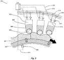
- FIG. 3 illustrates in schematic form a portion (301) of the pump (129) with electronically commutated valves.
- the pump consists of a number of similar working chambers (303) in a radial arrangement, of which only three are shown in the portion in Figure 3 .
- Each working chamber has a volume defined by the interior surface of a cylinder (305) and a piston (306), which is driven from a ring cam (307) by way of a roller (308), and which reciprocates within the cylinder to cyclically vary the volume of the working chamber.
- the ring cam may be broken into segments mounted on the shaft (322), which is firmly connected to the rotor shaft (125).
- a shaft position and speed sensor (309) determines the instantaneous angular position and speed of rotation of the shaft, and informs a controller (112), by way of electrical connection (311, being some of the pump actuation and pump shaft signals 171), which enables the controller to determine the instantaneous phase of the cycles of each individual working chamber.
- the controller is typically a microprocessor or microcontroller, which executes a stored program in use.
- the controller can take the form of a plurality of microprocessors or microcontrollers which may be distributed and which individually carry out a subset of the overall function of the controller.
- Each working chamber comprises a low pressure valve (LPV) in the form of an electronically actuated face-sealing poppet valve (313) which faces inwards toward the working chamber and is operable to selectively seal off a channel extending from the working chamber to a low pressure conduit (314), which functions generally (in the pumping mode) as a net source of fluid in use (or sink in the case of motoring).
- LUV low pressure valve
- the low pressure conduit is fluidically connected to the low pressure manifold (135).
- the LPV is a normally open solenoid closed valve which opens passively when the pressure within the working chamber is less than the pressure within the low pressure conduit, during an intake stroke, to bring the working chamber into fluid communication with the low pressure manifold, but is selectively closable under the active control of the controller via an electrical LPV control signal (315, being some of the pump actuation and pump shaft signals 171) to bring the working chamber out of fluid communication with the low pressure manifold.
- Alternative electronically controllable valves may be employed, such as normally closed solenoid opened valves.
- the working chamber further comprises a high pressure valve (HPV, 317) in the form of a pressure actuated delivery valve.
- HPV high pressure valve
- the HPV faces outwards from the working chamber and is operable to seal off a channel extending from the working chamber to a high pressure conduit (319), which functions as a net source or sink of fluid in use and is in fluid communication with the high pressure manifold (133).
- the HPV functions as a normally-closed pressuring-opening check valve which opens passively when the pressure within the working chamber exceeds the pressure within the high pressure manifold.
- the HPV may also function as a normally-closed solenoid opened check valve which the controller may selectively hold open via an HPV control signal (321, being some of the pump actuation and pump shaft signals 171) and once the HPV is opened, by pressure within the working chamber.
- the HPV may be openable under the control of the controller when there is pressure in the high pressure manifold but not in the working chamber, or may be partially openable.
- the controller selects the net rate of displacement of fluid to the high pressure manifold by the hydraulic pump by actively closing one or more of the LPVs typically near the point of maximum volume in the associated working chamber's cycle, closing the path to the low pressure manifold and thereby directing fluid out through the associated HPV on the subsequent contraction stroke.
- the controller selects the number and sequence of LPV closures to produce a flow or apply a torque to the shaft (322) to satisfy a selected net rate of displacement.
- the controller is operable to vary the precise phasing of the closure of the LPVs with respect to the varying working chamber volume and thereby to select the net rate of displacement of fluid from the low pressure manifold to the high pressure manifold.
- Figure 4 shows one time-step of the operation of a control algorithm (400) implementing the invention, and executed within the controller (112).
- the rotor speed W r is calculated from the rotor speed signal (117).
- the rotational speed of the pump may be measured as the pump and rotor are directly connected by the rotor shaft.
- a torque target, T d is calculated at step S2 from the rotor speed.
- step S2b shows step S2 in more detail, the aerodynamically ideal rotor torque T i is found in step S2a from a function of current rotor speed W r which is described in more detail with reference to Figure 6 .
- T i is scaled by an ideal torque scale factor M which would typically be between 0.9 and 1 and may vary during use, according to wind conditions and blade aerodynamic changes over time. M ⁇ 1 causes the pump to produce a small amount less torque than ideal for the average wind speed, and thereby to run slightly faster than ideal for the average wind speed.
- the algorithm also has the ability to adjust the torque applied to the rotor by the pump to cause the rotor to more closely follow rapid changes in wind speed and thereby extract maximum power from the wind even during gusts and lulls.
- the rotor acceleration a r is determined from the rate of change of the speed W r .
- step S2d the aerodynamic torque T aero (the actual amount of torque applied to the rotor by the wind at the present time) is discovered, being the sum of the torque applied to the rotor by the pump in the previous timestep T d (prev) (known from the selected net displacement rate of the pump and the measured pressure in the high pressure manifold) and the net torque that is accelerating the combined inertia of the rotor, pump and rotor shaft J rotor+pump .
- the algorithm computes the excess torque T excess over and above the pump torque, i.e. that torque which is expected to accelerate (if positive) or decelerate (if negative) the rotor, rotor shaft and pump.
- Step S2f comprises multiplying T excess by G, a feedforward gain, to calculate T feedforward .
- a more complex feedforward function could be used, for example a lead or lag controller, to improve tracking of wind speed even further.
- T feedforward is added to the ideal torque for maximum power capture T i , to find the torque demand T d that should be applied to the rotor by the pump to allow the rotor speed to track the wind speed accurately, while extracting maximum power when the rotor and wind speeds are matched by the optimum tip speed ratio.
- step S3 T d is divided by the measured pressure of the high pressure manifold (from the HP pressure signal, 154) to calculate a pump demand D pump .
- the pump demand is the selected net rate of displacement of the pump and is an output (402) of the control algorithm, used by the controller to selectively operate the LPVs (and possibly HPVs) of the pump in the manner described above.
- the controller calculates the power in the fluctuating energy flow Power rotor .
- This can be done in a number of different ways, for example: using the known rotation rate of the pump, the selected net rate of displacement of the pump, and the pressure in the high pressure manifold to calculate the hydraulic power output; or using the known rotation rate of the rotor and the estimated aerodynamic torque T aero to calculate the mechanical power output.
- a smoothed version of the fluctuating energy flow, Power motor is calculated at step S6, by executing a smoothing module, for example a first order low pass filter, on Power rotor .
- the designer may choose the smoothing algorithm to suit the WTG and the conditions.
- the smoothed version forms the basis of calculating the net rate of displacement of working fluid by the hydraulic motor, and is selected without regard to the effect of that rate on the pressure within the high pressure manifold, i.e. independently of it.
- a headroom torque, T h is calculated at step S7.
- the headroom torque defines the minimum torque the pump must be able to apply to the rotor shaft at 'short notice' to properly control the rotor speed during unexpected gusts or wind increases. (The headroom torque is a function of the rotational speed of the pump and its properties will be described in detail later with reference to Figure 6 .)
- Rotor torque is the product of the pump selected net rate of displacement per revolution (which has a design limit fixed by the number of working chambers and their volume) and high pressure manifold pressure, so the torque headroom requirement provides a lower limit to P min .
- a minimum pressure of the high pressure manifold, P min is calculated from T h in step S8, and defines the lower limit of the acceptable pressure range.
- P acc,min of the smoothing (or first and second accumulators) provides an additional lower limit to P min below which there may be insufficient compliance in the high pressure manifold to achieve desirable operation.
- P min and thus the acceptable pressure range, must be above both lower limits.
- the minimum pressure of the high pressure manifold P min , the design maximum pressure of said manifold P max (acting as an upper limit of the acceptable pressure range), and either the fluctuating energy flow or the smoothed version thereof, are used in step S9 to calculate a pressure controller gain, K p , according to the function described with respect to Figure 7 .
- a target pressure, P d is calculated from one or more of the optimum operating points of the WTG, the operating range limits of the WTG or a minimum pressure requirement, according to the function described with respect to Figure 8 .
- the algorithm calculates a nominal value for the net rate of displacement of the motor (motor demand), D n , at step S11.
- step S12 the algorithm calculates a motor demand correction, D b , by multiplying the difference between the measured pressure and the target pressure P d by the pressure controller gain K p .
- the final step of the algorithm, S13 calculates the net rate of displacement of the motor (motor demand), D motor , by adding together the nominal motor demand D n and the demand correction D b .
- the motor demand is an output of the control algorithm (404), used by the controller to selectively operate the valves of the motor in the manner described above.
- the algorithm is executed repeatedly in use.
- the rotor Before the WTG is affected by the gust, the rotor is spinning at near to the aerodynamic optimum speed. (If M is for example 0.97, the rotor spins a little faster than the aerodynamic optimum, so will already be running a little fast to thereby capture the impending and other gusts more efficiently.)
- the high pressure manifold pressure P s is equal to the optimal desired pressure P d (acting as the target pressure) determined with reference to the steady wind power and other conditions.
- the controller calculates the fluctuating energy flow Power rotor (step S4) from the ideal rotor torque MT i (or the estimated aerodynamic torque T aero ) and current rotor speed.
- Power motor is calculated by filtering the result of the addition with the low pass filter as described earlier with reference to step S6.
- the low pass filter means that immediately after the gust affects the WTG, and in contrast to WTGs of the prior art, the motor power (and thus the generator's electrical output) is substantially the same as immediately before the gust, despite the increase in wind power and the decrease in pump output.
- the controller detects rotor deceleration, increases the pump torque to slow the rotor to match the new wind speed, and in the process additional energy is stored in the accumulators and pressure P s rises further.
- the controller's low pass filter causes Power motor to decrease slowly after the gust ebbs, extracting fluid from the accumulators and returning pressure P s towards the optimum pressure P d . If there is any remaining discrepancy between P s and P d , the pressure controller 529 will adjust the motor demand D motor up or down slightly to ensure their eventual convergence.
- the pressure feedback controller gain K p will rise and the pressure feedback controller 529 will provide a stronger correction D b to increase the motor demand D motor and thereby avoid P s reaching P max .
- the electrical output of the generator will increase, but damage to the turbine is avoided.
- the result is a much more smooth generation of electricity than the WTGs of the prior art.
- the accumulators enable the output power of the WTG to be a time-averaged version of the instantaneous input power to the blades.
- the time constant of the low pass filter is related to the size of the hydraulic accumulators and the pump and the wind conditions at the site of the WTG's installation.
- the time constant is preferably chosen just long enough that the pressure does not extravagate the first range consequent to 90% of gusts or lulls, or for at least 95% of the operating time for example.
- the low pass filter behaviour may be adjusted in use according to changing wind conditions, acting as characteristics of the fluctuating enegy flow. It is preferable that when the expected energy of a gust or lull increases (for example, at high wind speeds or when the wind is from a direction associated with gusty conditions), the low pass filter's action is reduced so that the hydraulic motor responds more quickly to the gust and the high pressure manifold pressure does not rise too high.
- the controller may employ algorithms to learn the optimum filter parameters that provide the smallest variations in generator power output while keeping the pressure within the first range.
- the controller may determine a set of optimum filter parameters that are just long enough that the pressure does not extravagate the first pressure range consequent to 90% of gusts or lulls, or for at least 95% of the operating time for example.
- FIG. 5 shows a schematic of the signal flows in the implementation of the invention, equivalent to the execution flow diagram in Figure 4 .
- the rotor speed measurement (117) is used to calculate the ideal torque T i according to the function (600) defined with reference to Figure 6 .
- the ideal torque is adjusted by multiplying by an ideal torque scale factor M to give an adjusted ideal torque (MT i ).
- the ideal torque scale factor M can be any number between zero and one, and would typically be between 0.9 and 1.
- a slight reduction in pump torque allows the rotor to accelerate more rapidly during gusts, thus capturing more power than if the pump torque were not scaled from the ideal torque function (600).
- the scale factor will cause the rotor to decelerate more slowly, thus operating off its optimum operating point during lulls, however the additional power available due to tracking gusts is more significant than power loss due to sub-optimal operation during lulls.
- the torque target T d is the difference between the adjusted ideal torque and the output of a torque feedback controller (507).
- the torque feedback controller calculates an estimated aerodynamic torque, T aero , which is the sum of the current torque target and an acceleration torque which is derived from the angular acceleration of the rotor a r multiplied by the moment of rotational inertia of the energy extraction device, J.
- the output of the torque feedback controller is the difference T excess between the estimated aerodynamic torque and the adjusted ideal torque, which is then multiplied by a feedback gain, G to obtain a feedback torque T feedback .
- the feedback gain can be any number greater than or equal to zero, with a value of zero acting to disable the torque feedback controller.
- the torque feedback controller (507) will respond to the acceleration and deceleration of the energy extraction device by subtracting torque from the adjusted ideal torque MT i to slightly reduce the torque target T d in the case of acceleration, and adding torque to the adjusted ideal torque to slightly increase the torque target T d in the case of deceleration. This enables the rotor to accelerate and decelerate faster in response to changes in input energy than adjusted ideal torque control alone, hence allowing for greater total energy capture.
- the pump demand estimate (517) is calculated by dividing the torque target by the measured pressure of the pressurised hydraulic fluid (P s , 154).
- the pump demand estimate may be modified by a pressure limiter (518), which could be a PID type controller, the output of which is the pump demand output of the controller D pump (402).
- the pressure limiter acts to keep the pressure within the acceptable range, i.e. below a maximum level for safe operation of the WTG, by modifying the pump demanded rate of fluid quanta transfer.
- the pressure limit may be disabled in some operating modes wherein it is desirable to dissipate energy through the high pressure relief valve (155), for instance to prevent the turbine from operating above its rated speed during extreme gusts, or may be varied in use.
- the controller calculates the fluctuating energy flow Power rotor . (Alternatively this could be calculated from hydraulic information available to the controller: the rotation rate of the pump, the selected net rate of displacement of the pump, and the pressure in the high pressure manifold.)
- a smoothing module (525) in the form of a first order low pass filter smooths Power rotor to provide the motor throughput power Power motor .
- Power motor is divided by the measured hydraulic motor speed W motor and pressure of the pressurised hydraulic fluid P s to find the nominal motor demand D n .
- the motor throughput power informs a target pressure function (802, 812, 820) which provides a target pressure P d for the pressure feedback controller (529), which in turn uses a proportional gain K p to calculate a motor demand correction D b .
- K p is calculated based on where the current pressure P s lies within the acceptable pressure range (defined by maximum pressure P max of the high pressure manifold, and the minimum pressure P min ) and within the first and second ranges, according to a gain schedule function (700) described in more detail with reference to Figure 7 .
- the minimum pressure is calculated by dividing the headroom torque T h , which is a function (534) of rotor speed, by the maximum pump demand D max .
- the headroom torque function is described in more detail with reference to Figure 6 .
- the output hydraulic motor demand D motor (540) is the sum of the nominal motor demand D n and the motor demand correction D b .
- the invention has been shown with a proportional controller for the pressure feedback controller (529) and a first order low pass filter for the smoothing module (525). It is also possible to make alternative embodiments.
- the pressure feedback controller could be a proportional-integral controller (PI controller) with a low integral gain and the smoothing module and nominal motor demand D n may be removed altogether.
- PI controller proportional-integral controller
- a proportional-integral controller is selected from a set of candidate controllers in order to enhance the tracking of an output to an input, surprisingly we have found that if the integral gain is low enough then the controller acts to smooth the fluctuating energy flow to created a smoothed motor demand correction D b .
- FIG. 6 shows the aerodynamically ideal rotor torque (T, 598) as a function (600) of rotor speed (w r , 599), which is used in step S2a to determine the ideal torque T i ; according to which the pump regulates the torque it applies to the rotor.
- the controller unfeathers the blades by appropriate pitch actuation signals (121) to the pitch actuators (119), and releases any mechanical brakes.
- a minimum speed (601, i.e. section I in Figure 6 ) the ideal torque is substantially zero and the turbine accelerates up to the minimum speed without the pump applying any torque.
- the increasing torque profile causes the controller to command the pump to apply an increasing force to stabilise the turbine speed.
- the optimum torque for a WTG with fixed blade pitch is a function of the wind or rotor speed squared.
- the ideal torque curve follows this optimum profile and the controller pitches the blades to their (constant) optimum aerodynamic pitch by appropriate pitch actuation signals to the pitch actuators.
- section IV where the turbine is near its maximum operating speed, the torque curve becomes a steep linear function up to the torque of the source at the maximum pressure (the rated torque). The purpose of section IV is to limit the speed of the turbine, by ramping up the torque to its maximum value (603) over essentially a constant speed.
- the source has reached its maximum torque output, and the turbine is at its maximum speed.
- the controller actively controls the turbine speed by appropriate pitch actuation signals to the pitch actuators, and the pump is providing a constant (maximum) output torque.
- the headroom torque curve (610) is shown on the Figure as a dashed line.
- the headroom torque is shown as a quadratic function with, in section III, a constant offset from the optimum turbine torque, but may be another function which could even depend on other variables than the rotor speed.
- the application of this curve to the invention and the calculation of P min are described with reference to Figure 4 .
- the headroom torque curve may be adjusted during use according to changing wind conditions, for example expectations about the energy of gusts or lulls, based on experienced historical or current conditions.
- Figure 7 shows a typical pressure feedback controller gain K p (700) as a function of pressure P (702).
- the parameter P min varies as just described with rotor speed, so Figure 7 shows a characteristic K p function at low speed (704) and a characteristic K p function at high speed (706).
- the acceptable pressure range (defined by the range P min to P max ) varies with the current rotation rate of the rotating shaft.
- the controller gain is set at the maximum gain K max (712).
- K max is also high, in this example also K max although any other high gain value may be chosen.
- the motor net rate of displacement D motor is strongly controlled to bring the pressure within the allowable range.
- the controller gain is constant at K min (718) which is non-zero but low enough that the pressure is substantially unregulated.
- K min 718
- the controller gain is constant at K min (718) which is non-zero but low enough that the pressure is substantially unregulated.
- K p increases linearly from K min to K max .
- the strength of pressure regulation increases progressively as the pressure approaches the limits P min or P max , i.e. moves further into the second ranges. This has the benefit of reducing the likelihood that the pressure will reach either of those limits in use as the motor net rate of displacement D motor is more strongly controlled to maintain the pressure within the allowable range.
- FIG. 8 shows examples of the types of target pressure functions that could be implemented by the invention.
- the target pressure functions define a target pressure (528) for the pressure feedback controller (529) that is a function of the fluctuating energy flow Power rotor or the low-pass filtered version Power motor (800), with the shape of the function being determined from a wide range of variables as will be explained.
- the dot-dashed line (802) shows a first target pressure function wherein the target pressure is equal to or just larger than the constant minimum pressure P acc,min (804) in a first region (I) spanning from zero power to a first power (806), is equal to the constant maximum pressure P max (808) in a fifth region (V) spanning from a fourth power (810) to the maximum rated power Power motor,max , and increases linearly with Power motor between the first region and the fifth region.
- the minimum precharge pressure P acc,min is a lower limit to pressure below which there is insufficient compliance fluidically connected to the high pressure manifold, i.e. below the precharge pressure of the smoothing or first or second accumulators.
- the maximum pressure P max is related to the maximum allowable operating pressure of the pressurised hydraulic fluid, considering component lifetimes and the setting of the high pressure relief valve (155).
- the target pressure is responsive to characteristics of the fluctuating energy flow, the hydraulic pump and motor, and the accumulators.
- the first target pressure function provides the benefit of ensuring that there is enough pressure for the pump to apply maximum torque to the rotor at high power conditions (i.e. in the fifth region V).
- the first target pressure function further provides the benefit of ensuring that in the first region (I) in which the kinetic energy in the rotor is low, the pressure is maintained low enough that the relative energy absorbed by individual working chamber activations of the pump is not sufficient to apply too much torque to the blades or other parts of the WTG, while still being above the minimum allowable pressure P min .
- a second target pressure function is shown with a solid line (812).
- This function is similar to the first target pressure function in regions I and V, but further comprises a third region (III) spanning from a second power (814) to a third power (816) in which the target pressure is an optimum pressure P opt (818), and second (II) and fourth regions (IV) spanning from the first to the second powers and from the third to the fourth powers respectively, which provide for a smooth change in target pressure between the adjacent regions.
- Optimum pressure P opt is a pressure at which the pump and the motor (and all the other hydraulic components) together work at optimal hydraulic efficiency.
- P opt may be found by experiment, simulation or calculation, or any combination thereof. It may be that the pump and/or the motor are designed to be optimally efficient at P opt , which may be chosen by the designer.
- the target pressure is responsive to characteristics of the fluctuating energy flow, the hydraulic pump and the hydraulic motor.
- the second target pressure function provides the benefit of ensuring that the WTG transmission operates where possible at an optimal pressure and thus that its energy productivity is maximised.
- a third target pressure function is shown with a dashed line (820). This function defines a target pressure that is closer to the minimum system pressure, rather than the maximum, over the majority of the operating power throughput levels of the WTG.
- the advantage of the third target pressure function is that the accumulators are generally at a low state of charge to maximise the storage available to accept energy from gusts of wind, and also to operate the WTG at high rates of fluid flow, rather than high pressure, which may be desirable to reduce vibration and or noise, or to increase the lifetime of the WTG.
- the particular target pressure function that is implemented may change on a second-by-second basis with respect to other parameters, for example, throughput power estimates from an external source, the estimated lifetime and efficiency of components of the WTG, the need to start or stop the WTG or any other desired operating mode of the WTG.
- the controller selects the second target pressure function (812) so that the pressure is typically optimised for hydraulic efficiency
- the controller selects the third target pressure function (820) so that the first and second accumulators can absorb the energy of the gusts.
- the target pressure is changed (reduced) in anticipation of energy being received from the fluctuating energy source at a rate which would cause the pressure in the high pressure manifold to exceed a threshold (entering the upper second range (720).
- the WTG controller may select the third target pressure function (820) over the second target pressure function (812) responsive to detection of a small leak, because the third target pressure function maintains a lower pressure which will make the leak less severe, and is also less likely to lead to a major failure.
- the controller may of course blend any of the target pressure functions together to create an infinite number of variations, optimised for any conditions and location.
- the controller is also able to control the heat exchanger (144) and can thus regulate the working fluid temperature.
- the controller sets the working fluid temperature based on the target pressure at the current time, according to an optimisation function which minimises the combined hydraulic energy losses from working fluid leakage (typically between the cylinders and the pistons of the working chambers) and from flow losses (typically through the valves of the pump and motor, and the conduits connecting the pump and motor).
- working fluid leakage typically between the cylinders and the pistons of the working chambers
- flow losses typically through the valves of the pump and motor, and the conduits connecting the pump and motor.
- the viscosity of the working fluid falls at higher temperatures.
- the leakage losses increase exponentially at higher operating pressures, and so the controller regulates the working fluid to a lower temperature (i.e. higher fluid viscosity), whereas the flow losses dominate at lower pressures, so the controller regulates the working fluid to a higher temperature (i.e. lower fluid viscosity).
Landscapes
- Engineering & Computer Science (AREA)
- General Engineering & Computer Science (AREA)
- Mechanical Engineering (AREA)
- Life Sciences & Earth Sciences (AREA)
- Sustainable Development (AREA)
- Sustainable Energy (AREA)
- Chemical & Material Sciences (AREA)
- Combustion & Propulsion (AREA)
- Power Engineering (AREA)
- Wind Motors (AREA)
- Fluid-Pressure Circuits (AREA)
- Other Liquid Machine Or Engine Such As Wave Power Use (AREA)
Claims (17)
- Procédé de commande d'un dispositif d'extraction d'énergie (100) permettant d'extraire de l'énergie d'un flux d'énergie variable issu d'une source d'énergie renouvelable, le dispositif comprenant: une pompe hydraulique (129) entraînée par un arbre rotatif (125), l'arbre rotatif étant entraîné par une source d'énergie renouvelable, un moteur hydraulique (131) entraînant une charge, au moins un collecteur basse pression (135) et un collecteur haute pression (133) en communication fluidique avec une sortie de la pompe hydraulique, une entrée du moteur hydraulique et un corps de retenue de fluide élastiquement déformable (147, 149), la pompe hydraulique et le moteur hydraulique comprenant chacun une pluralité de chambres de travail (202 A à H) dont le volume varie de façon cyclique et une pluralité de soupapes (214) pour réguler le déplacement net de fluide de travail entre chaque chambre de travail et chaque collecteur, au moins une soupape associée à chaque chambre de travail étant une soupape à commande électronique (214), lesdites soupapes à commande électronique étant actionnées de manière à sélectionner le volume de fluide de travail déplacé par chacune desdites chambres de travail lors de chaque cycle de volume de chambre de travail et à réguler ainsi le débit net de déplacement de fluide de travail par chacun de la pompe hydraulique et du moteur hydraulique,
le procédé étant caractérisé par la mesure de la pression dans le collecteur haute pression, la sélection du débit net de déplacement de fluide de travail par la pompe hydraulique en réponse à ladite pression mesurée afin de réguler le couple appliqué audit arbre rotatif, la sélection du débit net de déplacement de fluide de travail par le moteur hydraulique afin de lisser le flux d'énergie vers la charge, et en outre la sélection du débit net de déplacement de fluide de travail par le moteur hydraulique afin de réguler la pression dans le collecteur haute pression de manière à rester à l'intérieur d'une plage de pression acceptable. - Procédé selon la revendication 1, dans lequel la plage de pression acceptable comprend une première plage et une deuxième plage, ou des deuxièmes plages, supérieure(s) ou inférieure(s) à la première plage, et la pression à l'intérieur du collecteur haute pression est régulée plus fortement lorsque la pression se situe à l'intérieur de la ou de chaque deuxième plage et, de préférence, dans lequel la force de la régulation de pression augmente progressivement lorsque la pression avance davantage dans la deuxième plage.
- Procédé selon la revendication 2, dans lequel la pression à l'intérieur du collecteur haute pression est sensiblement non régulée lorsque la pression se situe à l'intérieur de la première plage et, de préférence, dans lequel lorsque la pression à l'intérieur du collecteur haute pression se situe à l'intérieur de la première plage, le débit net de déplacement de fluide de travail par le moteur est sélectionné sans tenir compte de l'impact de ce débit sur la pression l'intérieur du collecteur haute pression.
- Procédé selon la revendication 2 ou la revendication 3, dans lequel le débit net de déplacement de fluide de travail par le moteur hydraulique est sélectionné en fonction de la pression à l'intérieur du collecteur haute pression, et le débit net sélectionné de déplacement de fluide de travail par le moteur hydraulique change dans une plus grande mesure pour une variation de pression donnée à l'intérieur du collecteur haute pression dans la seconde plage que dans la première plage.
- Procédé selon l'une quelconque des revendications précédentes, dans lequel la pression dans le collecteur haute pression est régulée vers une pression ou une plage de pressions cible (typiquement optimale) et, de préférence, dans lequel la pression ou la plage de pressions cible est variable.
- Procédé selon la revendication 5, dans lequel la pression est régulée vers la pression cible, ou une plage de pressions cible, plus fortement lorsque la pression à l'intérieur du collecteur haute pression se situe à l'intérieur de la ou de chaque seconde plage qu'à l'intérieur de la première plage.
- Procédé selon la revendication 5 ou la revendication 6, comprenant la sélection d'une pression ou d'une plage de pressions cible à l'intérieur du collecteur haute pression en réponse à une ou plusieurs caractéristique(s) du flux d'énergie variable, de la pompe hydraulique, du moteur hydraulique, du corps de retenue élastiquement déformable ou de la charge.
- Procédé selon l'une quelconque des revendications 5 à 7, dans lequel la pression ou la plage de pressions cible est modifiée par anticipation de l'énergie reçue en provenance de la source d'énergie variable à un débit qui dépasse un seuil ou pour amener la pression à l'intérieur du collecteur haute pression à dépasser un seuil.
- Procédé selon l'une quelconque des revendications précédentes, dans lequel la plage de pression acceptable est variable et, de préférence, dans lequel la plage de pression acceptable varie selon une fonction comprenant un ou plusieurs facteur(s) parmi la vitesse de rotation actuelle de l'arbre rotatif ou les caractéristiques du flux d'énergie variable.
- Procédé selon l'une quelconque des revendications précédentes, dans lequel, lorsque la pression dépasse un seuil (fixe ou variable), une action est entreprise pour réduire le débit net de déplacement de fluide de travail par la pompe hydraulique.
- Procédé selon la revendication 10, dans lequel, lorsque la pression dépasse le seuil, le dispositif d'extraction d'énergie est commandé de manière à réduire le couple transmis à l'arbre rotatif par la source d'énergie renouvelable.
- Procédé selon l'une quelconque des revendications précédentes, dans lequel le couple appliqué à l'arbre rotatif est régulé selon une fonction comprenant un ou plusieurs facteur(s) parmi la vitesse de rotation actuelle de l'arbre rotatif et la vitesse de variation de la vitesse de rotation de l'arbre rotatif.
- Procédé selon l'une quelconque des revendications précédentes, dans lequel le fonctionnement desdites soupapes à commande électronique est réglé de manière à compenser un ou plusieurs facteur(s) parmi la compression ou la fuite du fluide de travail ou des pertes d'énergie causées par le flux du fluide de travail.
- Procédé selon l'une quelconque des revendications précédentes, dans lequel le moteur hydraulique comprend une pluralité de moteurs hydrauliques.
- Procédé selon l'une quelconque des revendications 2 à 14, dans lequel un calcul de lissage est exécuté, comprenant les étapes de calcul de l'énergie extraite à partir du flux d'énergie variable par le dispositif d'extraction d'énergie, le calcul d'une version lissée de celui-ci, et la sélection du débit net de déplacement de fluide de travail par le moteur hydraulique en réponse à ladite version lissée.
- Dispositif d'extraction d'énergie permettant d'extraire de l'énergie d'un flux d'énergie variable issu d'une source d'énergie renouvelable, le dispositif comprenant: un dispositif de commande, une pompe hydraulique entraînée par un arbre rotatif, l'arbre rotatif étant entraîné par une source d'énergie renouvelable, un moteur hydraulique entraînant une charge, au moins un collecteur basse pression, un collecteur haute pression en communication fluidique avec une sortie de la pompe hydraulique, une entrée du moteur hydraulique et un corps de retenue de fluide élastiquement déformable, un capteur de pression pour mesurer la pression dans le collecteur haute pression et la pompe hydraulique et le moteur hydraulique comprenant chacun une pluralité de chambres de travail dont le volume varie de façon cyclique et une pluralité de soupapes pour réguler le débit net de déplacement de fluide de travail entre chaque chambre de travail et chaque collecteur, au moins une soupape associée à chaque chambre de travail étant une soupape à commande électronique, lesdites soupapes à commande électronique pouvant être commandées par le dispositif de commande de manière à sélectionner le volume de fluide de travail déplacé par chacune desdites chambres de travail lors de chaque cycle de volume de chambre de travail et à réguler ainsi le débit net de déplacement de fluide de travail par chacun de la pompe hydraulique et du moteur hydraulique, dans lequel le dispositif de commande est actionnable pour amener le dispositif d'extraction d'énergie à fonctionner selon le procédé selon l'une quelconque des revendications précédentes.
- Support de stockage lisible par un ordinateur contenant des instructions de code de programme qui, lorsqu'elles sont exécutées par le dispositif de commande d'une machine d'extraction d'énergie, amènent la machine d'extraction d'énergie à exécuter le procédé selon l'une quelconque des revendications 1 à 15.
Applications Claiming Priority (2)
| Application Number | Priority Date | Filing Date | Title |
|---|---|---|---|
| GB1009013A GB2480684A (en) | 2010-05-28 | 2010-05-28 | A method and apparatus for operating a renewable energy extraction device |
| PCT/EP2011/058865 WO2011147996A2 (fr) | 2010-05-28 | 2011-05-30 | Procédé et appareil permettant d'extraire de l'énergie d'un flux d'énergie variable issu d'une source d'énergie renouvelable |
Publications (2)
| Publication Number | Publication Date |
|---|---|
| EP2414672A2 EP2414672A2 (fr) | 2012-02-08 |
| EP2414672B1 true EP2414672B1 (fr) | 2017-03-01 |
Family
ID=42371196
Family Applications (1)
| Application Number | Title | Priority Date | Filing Date |
|---|---|---|---|
| EP11729387.8A Not-in-force EP2414672B1 (fr) | 2010-05-28 | 2011-05-30 | Procédé et appareil permettant d'extraire de l'énergie d'un flux d'énergie variable issu d'une source d'énergie renouvelable |
Country Status (8)
| Country | Link |
|---|---|
| US (1) | US9103438B2 (fr) |
| EP (1) | EP2414672B1 (fr) |
| JP (1) | JP5347066B2 (fr) |
| KR (1) | KR101331686B1 (fr) |
| CN (1) | CN102597510B (fr) |
| AU (1) | AU2011226999A1 (fr) |
| GB (1) | GB2480684A (fr) |
| WO (1) | WO2011147996A2 (fr) |
Families Citing this family (28)
| Publication number | Priority date | Publication date | Assignee | Title |
|---|---|---|---|---|
| US10435145B1 (en) | 2009-07-02 | 2019-10-08 | Alfred Finnell | Vehicle with tension wing assembly |
| US10443569B1 (en) * | 2009-07-02 | 2019-10-15 | Alfred Finnell | Wind or water based power generating system |
| US11021243B1 (en) | 2009-07-02 | 2021-06-01 | Alfred Finnell | Tension airfoil assembly and implementation for power generation and aviation |
| WO2012022924A1 (fr) | 2010-08-17 | 2012-02-23 | Artemis Intelligent Power Limited | Machine entraînée par fluide pourvue d'une came annulaire à lobes multiples |
| GB2484890A (en) | 2010-08-17 | 2012-05-02 | Artemis Intelligent Power Ltd | Ring cam ensuring smooth follower handover between segments |
| GB2485987A (en) * | 2010-11-30 | 2012-06-06 | Mitsubishi Heavy Ind Ltd | Renewable energy extraction device tolerant of grid failures |
| CA2724564A1 (fr) | 2010-11-30 | 2012-05-30 | Mitsubishi Heavy Industries, Ltd. | Generatrice eolienne a transmission hydraulique |
| NL2008103C2 (en) * | 2011-03-14 | 2013-07-15 | Nestor Man Consultants B V | Transmission. |
| EP2565442A1 (fr) * | 2011-09-05 | 2013-03-06 | Siemens Aktiengesellschaft | Système et procédé de fonctionnement d'une éolienne utilisant des variables de référence adaptatives |
| WO2013080397A1 (fr) | 2011-11-30 | 2013-06-06 | Mitsubishi Heavy Industries, Ltd. | Appareil générateur d'énergie d'un type à énergie renouvelable et procédé de fonctionnement de celui-ci |
| KR101967148B1 (ko) * | 2012-03-27 | 2019-04-10 | 한국전력공사 | 유압식 풍력 발전 장치 및 그 방법 |
| CN103114967B (zh) * | 2013-02-28 | 2014-09-17 | 浙江大学 | 风浪互补液压传动发电装置及其控制方法 |
| JP6097134B2 (ja) * | 2013-04-26 | 2017-03-15 | 三菱重工業株式会社 | ラジアルピストン式油圧機械及び油圧トランスミッション、並びに風力発電装置 |
| JP6203649B2 (ja) * | 2014-01-24 | 2017-09-27 | 三菱重工業株式会社 | 油圧トランスミッション及び再生エネルギー型発電装置、並びにそれらの運転方法 |
| AT515328A2 (de) * | 2014-02-04 | 2015-08-15 | Bernecker & Rainer Ind Elektronik Gmbh | Verfahren zur Ermittlung von Größen einer Betriebs- oder Maschinendatenerfassung |
| JP6165703B2 (ja) * | 2014-12-02 | 2017-07-19 | 三菱重工業株式会社 | 油圧システム及び再生エネルギー型発電装置、並びにその運転方法 |
| JP5823646B1 (ja) * | 2015-07-10 | 2015-11-25 | 松尾建設株式会社 | 自律式安定供給型再生可能エネルギー制御装置 |
| CN105512492B (zh) * | 2015-12-22 | 2018-09-07 | 重庆大学 | 潮汐流能发电机输出功率的概率建模方法 |
| CN110662901B (zh) | 2017-05-23 | 2023-10-31 | 新叶管理有限公司 | 用于使用系缆翼型利用风能的方法和系统 |
| GB2566095B (en) * | 2017-09-04 | 2019-10-02 | Artemis Intelligent Power Ltd | Hydraulic multi-rotor aerial vehicle |
| WO2019058716A1 (fr) | 2017-09-22 | 2019-03-28 | 三菱日立パワーシステムズ株式会社 | Équipement de production d'énergie thermique solaire |
| EP3620582B1 (fr) * | 2018-09-10 | 2022-03-09 | Artemis Intelligent Power Limited | Appareil comportant un circuit hydraulique |
| DE102018009333A1 (de) * | 2018-11-28 | 2020-05-28 | Senvion Gmbh | Verfahren zum Betrieb einer Windenergieanlage |
| EP3674546B1 (fr) * | 2018-12-28 | 2022-07-13 | Artemis Intelligent Power Limited | Synchronisation de soupape dans une machine hydraulique commutée électroniquement |
| KR102169545B1 (ko) | 2019-05-28 | 2020-10-26 | 수원대학교산학협력단 | 재생에너지 기반 전력 생산 구조 |
| US11261846B2 (en) * | 2019-11-01 | 2022-03-01 | General Electric Company | System and method for designing and operating a wind turbine power system based on statistical analysis of operational and/or grid data thereof |
| EP4226039B1 (fr) | 2020-10-06 | 2024-09-18 | Vestas Wind Systems A/S | Système de transmission de puissance pour éolienne |
| US11959589B2 (en) | 2022-04-11 | 2024-04-16 | Hamilton Sundstrand Corporation | Motor driven pump for variable speed power generation cooling |
Family Cites Families (25)
| Publication number | Priority date | Publication date | Assignee | Title |
|---|---|---|---|---|
| CA1128993A (fr) | 1977-03-10 | 1982-08-03 | Henry Lawson-Tancred | Production d'electricite a l'aide d'un appareil fonctionnant sous l'impulsion de sources d'energie dissemblables |
| US4280061A (en) | 1978-10-25 | 1981-07-21 | Sir Henry Lawson-Tancred, Sons & Co. Ltd. | Method and apparatus for generating electricity from a fixed pitch wind wheel |
| US4503673A (en) * | 1979-05-25 | 1985-03-12 | Charles Schachle | Wind power generating system |
| JPS56167873A (en) * | 1980-05-28 | 1981-12-23 | Shimadzu Corp | Wind power generator |
| US4496847A (en) | 1982-06-04 | 1985-01-29 | Parkins William E | Power generation from wind |
| GB8822901D0 (en) | 1988-09-29 | 1988-11-02 | Mactaggart Scot Holdings Ltd | Apparatus & method for controlling actuation of multi-piston pump &c |
| EP0494236B1 (fr) | 1988-09-29 | 1995-12-13 | Artemis Intelligent Power Ltd. | Machine a fonctionnement fluidique ameliore |
| US5145324A (en) * | 1990-06-18 | 1992-09-08 | Sundstrand Corporation | RAM air turbine driving a variable displacement hydraulic pump |
| GB0221165D0 (en) | 2002-09-12 | 2002-10-23 | Artemis Intelligent Power Ltd | Fluid-working machine and operating method |
| JP2005248738A (ja) * | 2004-03-02 | 2005-09-15 | Fuchu Giken:Kk | 風力発電装置の運転制御方法 |
| JP3981690B2 (ja) | 2005-03-28 | 2007-09-26 | 東京電力株式会社 | 統括風力発電システム |
| US7183664B2 (en) | 2005-07-27 | 2007-02-27 | Mcclintic Frank | Methods and apparatus for advanced wind turbine design |
| WO2007053036A1 (fr) | 2005-10-31 | 2007-05-10 | Chapdrive As | Systeme de production d'energie electrique a turbine et procede de commande dudit systeme |
| US7485979B1 (en) * | 2005-11-17 | 2009-02-03 | Staalesen Haakon A | Method and system for controlling power generator having hydraulic motor drive |
| GB0614940D0 (en) * | 2006-07-27 | 2006-09-06 | Arternis Intelligent Power Ltd | Vehicle traction and stability control system employing control of fluid quanta |
| JP4994455B2 (ja) | 2006-09-08 | 2012-08-08 | アルテミス インテリジェント パワー リミティド | 流体作動機械およびその弁構成 |
| WO2008113699A2 (fr) | 2007-03-21 | 2008-09-25 | Rle-International Gmbh | Dispositif de conversion d'énergie à système d'entraînement hydraulique |
| DE202007014676U1 (de) * | 2007-10-19 | 2009-02-26 | Liebherr-Machines Bulle S.A. | Hydraulisches Antriebssystem |
| EP2055945B8 (fr) * | 2007-11-01 | 2017-12-06 | Danfoss Power Solutions Aps | Procédé pour la commande d'une machine de travail pour fluides |
| US7926267B2 (en) * | 2008-03-20 | 2011-04-19 | Caterpillar Inc. | Hystat transmission having pressure override control |
| US8074450B2 (en) * | 2008-08-13 | 2011-12-13 | General Electric Company | Wind energy system with fluid-working machine with non-symmetric actuation |
| US8602381B2 (en) | 2008-09-09 | 2013-12-10 | Artemis Intelligent Power Limited | Valve assemblies |
| GB2463647B (en) | 2008-09-17 | 2012-03-14 | Chapdrive As | Turbine speed stabillisation control system |
| GB0817202D0 (en) | 2008-09-19 | 2008-10-29 | Wesby Philip B | System and method for hydraulic power transfer |
| WO2011104544A2 (fr) | 2010-02-23 | 2011-09-01 | Artemis Intelligent Power Limited | Machine à fluide de travail à piston radiaux et à déplacement variable |
-
2010
- 2010-05-28 GB GB1009013A patent/GB2480684A/en not_active Withdrawn
-
2011
- 2011-05-30 KR KR1020117024226A patent/KR101331686B1/ko active IP Right Grant
- 2011-05-30 US US13/380,136 patent/US9103438B2/en not_active Expired - Fee Related
- 2011-05-30 WO PCT/EP2011/058865 patent/WO2011147996A2/fr active Application Filing
- 2011-05-30 JP JP2012516802A patent/JP5347066B2/ja not_active Expired - Fee Related
- 2011-05-30 CN CN201180001498.8A patent/CN102597510B/zh not_active Expired - Fee Related
- 2011-05-30 AU AU2011226999A patent/AU2011226999A1/en not_active Abandoned
- 2011-05-30 EP EP11729387.8A patent/EP2414672B1/fr not_active Not-in-force
Non-Patent Citations (1)
| Title |
|---|
| None * |
Also Published As
| Publication number | Publication date |
|---|---|
| US20120096844A1 (en) | 2012-04-26 |
| WO2011147996A2 (fr) | 2011-12-01 |
| US9103438B2 (en) | 2015-08-11 |
| CN102597510A (zh) | 2012-07-18 |
| WO2011147996A3 (fr) | 2012-04-19 |
| KR20120018287A (ko) | 2012-03-02 |
| EP2414672A2 (fr) | 2012-02-08 |
| JP5347066B2 (ja) | 2013-11-20 |
| GB201009013D0 (en) | 2010-07-14 |
| KR101331686B1 (ko) | 2013-11-20 |
| CN102597510B (zh) | 2015-08-12 |
| JP2012522185A (ja) | 2012-09-20 |
| AU2011226999A1 (en) | 2011-12-15 |
| GB2480684A (en) | 2011-11-30 |
Similar Documents
| Publication | Publication Date | Title |
|---|---|---|
| EP2577056B1 (fr) | Procédé et appareil destinés à extraire l'énergie d'un flux d'énergie fluctuante provenant d'une source d'énergie renouvelable | |
| EP2414672B1 (fr) | Procédé et appareil permettant d'extraire de l'énergie d'un flux d'énergie variable issu d'une source d'énergie renouvelable | |
| JP5656977B2 (ja) | エネルギー抽出装置、エネルギー抽出装置群および運転方法 | |
| EP2486273B1 (fr) | Dispositif pour l'extraction d'énergierenouvelable comme une éolienne avec une transmission hydraulique | |
| EP2454478B1 (fr) | Appareil de production d'energie de type energie renouvelable et procede de fonctionnement correspondant | |
| EP2649348B1 (fr) | Transmission hydraulique comprenant une pompe ou un moteur à cylindrée variable pouvant fonctionner dans une plage de déplacements discontinue | |
| JP5583204B2 (ja) | エネルギー抽出装置およびエネルギー抽出装置の運転方法 | |
| EP2721294B1 (fr) | Procédé de synchronisation d'un dispositif d'entraînement de générateur avec un réseau électrique à courant alternatif | |
| EP2721295B1 (fr) | Générateur d'énergie renouvelable et son procédé de fonctionnement |
Legal Events
| Date | Code | Title | Description |
|---|---|---|---|
| PUAI | Public reference made under article 153(3) epc to a published international application that has entered the european phase |
Free format text: ORIGINAL CODE: 0009012 |
|
| 17P | Request for examination filed |
Effective date: 20110930 |
|
| AK | Designated contracting states |
Kind code of ref document: A2 Designated state(s): AL AT BE BG CH CY CZ DE DK EE ES FI FR GB GR HR HU IE IS IT LI LT LU LV MC MK MT NL NO PL PT RO RS SE SI SK SM TR |
|
| R17D | Deferred search report published (corrected) |
Effective date: 20120419 |
|
| DAX | Request for extension of the european patent (deleted) | ||
| GRAP | Despatch of communication of intention to grant a patent |
Free format text: ORIGINAL CODE: EPIDOSNIGR1 |
|
| INTG | Intention to grant announced |
Effective date: 20160926 |
|
| GRAJ | Information related to disapproval of communication of intention to grant by the applicant or resumption of examination proceedings by the epo deleted |
Free format text: ORIGINAL CODE: EPIDOSDIGR1 |
|
| GRAR | Information related to intention to grant a patent recorded |
Free format text: ORIGINAL CODE: EPIDOSNIGR71 |
|
| GRAS | Grant fee paid |
Free format text: ORIGINAL CODE: EPIDOSNIGR3 |
|
| GRAA | (expected) grant |
Free format text: ORIGINAL CODE: 0009210 |
|
| INTC | Intention to grant announced (deleted) | ||
| AK | Designated contracting states |
Kind code of ref document: B1 Designated state(s): AL AT BE BG CH CY CZ DE DK EE ES FI FR GB GR HR HU IE IS IT LI LT LU LV MC MK MT NL NO PL PT RO RS SE SI SK SM TR |
|
| INTG | Intention to grant announced |
Effective date: 20170120 |
|
| REG | Reference to a national code |
Ref country code: GB Ref legal event code: FG4D |
|
| REG | Reference to a national code |
Ref country code: CH Ref legal event code: EP Ref country code: AT Ref legal event code: REF Ref document number: 871695 Country of ref document: AT Kind code of ref document: T Effective date: 20170315 |
|
| REG | Reference to a national code |
Ref country code: IE Ref legal event code: FG4D |
|
| REG | Reference to a national code |
Ref country code: DE Ref legal event code: R096 Ref document number: 602011035409 Country of ref document: DE |
|
| REG | Reference to a national code |
Ref country code: FR Ref legal event code: PLFP Year of fee payment: 7 |
|
| REG | Reference to a national code |
Ref country code: NL Ref legal event code: MP Effective date: 20170301 |
|
| REG | Reference to a national code |
Ref country code: LT Ref legal event code: MG4D |
|
| REG | Reference to a national code |
Ref country code: AT Ref legal event code: MK05 Ref document number: 871695 Country of ref document: AT Kind code of ref document: T Effective date: 20170301 |
|
| PG25 | Lapsed in a contracting state [announced via postgrant information from national office to epo] |
Ref country code: GR Free format text: LAPSE BECAUSE OF FAILURE TO SUBMIT A TRANSLATION OF THE DESCRIPTION OR TO PAY THE FEE WITHIN THE PRESCRIBED TIME-LIMIT Effective date: 20170602 Ref country code: LT Free format text: LAPSE BECAUSE OF FAILURE TO SUBMIT A TRANSLATION OF THE DESCRIPTION OR TO PAY THE FEE WITHIN THE PRESCRIBED TIME-LIMIT Effective date: 20170301 Ref country code: NO Free format text: LAPSE BECAUSE OF FAILURE TO SUBMIT A TRANSLATION OF THE DESCRIPTION OR TO PAY THE FEE WITHIN THE PRESCRIBED TIME-LIMIT Effective date: 20170601 Ref country code: FI Free format text: LAPSE BECAUSE OF FAILURE TO SUBMIT A TRANSLATION OF THE DESCRIPTION OR TO PAY THE FEE WITHIN THE PRESCRIBED TIME-LIMIT Effective date: 20170301 Ref country code: HR Free format text: LAPSE BECAUSE OF FAILURE TO SUBMIT A TRANSLATION OF THE DESCRIPTION OR TO PAY THE FEE WITHIN THE PRESCRIBED TIME-LIMIT Effective date: 20170301 |
|
| REG | Reference to a national code |
Ref country code: DE Ref legal event code: R082 Ref document number: 602011035409 Country of ref document: DE Representative=s name: MICHALSKI HUETTERMANN & PARTNER PATENTANWAELTE, DE Ref country code: DE Ref legal event code: R081 Ref document number: 602011035409 Country of ref document: DE Owner name: MITSUBISHI HEAVY INDUSTRIES, LTD., JP Free format text: FORMER OWNER: ARTEMIS INTELLIGENT POWER LIMITED, LOANHEAD, GB |
|
| PG25 | Lapsed in a contracting state [announced via postgrant information from national office to epo] |
Ref country code: RS Free format text: LAPSE BECAUSE OF FAILURE TO SUBMIT A TRANSLATION OF THE DESCRIPTION OR TO PAY THE FEE WITHIN THE PRESCRIBED TIME-LIMIT Effective date: 20170301 Ref country code: SE Free format text: LAPSE BECAUSE OF FAILURE TO SUBMIT A TRANSLATION OF THE DESCRIPTION OR TO PAY THE FEE WITHIN THE PRESCRIBED TIME-LIMIT Effective date: 20170301 Ref country code: AT Free format text: LAPSE BECAUSE OF FAILURE TO SUBMIT A TRANSLATION OF THE DESCRIPTION OR TO PAY THE FEE WITHIN THE PRESCRIBED TIME-LIMIT Effective date: 20170301 Ref country code: LU Free format text: LAPSE BECAUSE OF NON-PAYMENT OF DUE FEES Effective date: 20170531 Ref country code: ES Free format text: LAPSE BECAUSE OF FAILURE TO SUBMIT A TRANSLATION OF THE DESCRIPTION OR TO PAY THE FEE WITHIN THE PRESCRIBED TIME-LIMIT Effective date: 20170301 Ref country code: LV Free format text: LAPSE BECAUSE OF FAILURE TO SUBMIT A TRANSLATION OF THE DESCRIPTION OR TO PAY THE FEE WITHIN THE PRESCRIBED TIME-LIMIT Effective date: 20170301 Ref country code: BG Free format text: LAPSE BECAUSE OF FAILURE TO SUBMIT A TRANSLATION OF THE DESCRIPTION OR TO PAY THE FEE WITHIN THE PRESCRIBED TIME-LIMIT Effective date: 20170601 |
|
| PG25 | Lapsed in a contracting state [announced via postgrant information from national office to epo] |
Ref country code: NL Free format text: LAPSE BECAUSE OF FAILURE TO SUBMIT A TRANSLATION OF THE DESCRIPTION OR TO PAY THE FEE WITHIN THE PRESCRIBED TIME-LIMIT Effective date: 20170301 |
|
| REG | Reference to a national code |
Ref country code: GB Ref legal event code: 732E Free format text: REGISTERED BETWEEN 20170914 AND 20170920 |
|
| PG25 | Lapsed in a contracting state [announced via postgrant information from national office to epo] |
Ref country code: IT Free format text: LAPSE BECAUSE OF FAILURE TO SUBMIT A TRANSLATION OF THE DESCRIPTION OR TO PAY THE FEE WITHIN THE PRESCRIBED TIME-LIMIT Effective date: 20170301 Ref country code: CZ Free format text: LAPSE BECAUSE OF FAILURE TO SUBMIT A TRANSLATION OF THE DESCRIPTION OR TO PAY THE FEE WITHIN THE PRESCRIBED TIME-LIMIT Effective date: 20170301 Ref country code: EE Free format text: LAPSE BECAUSE OF FAILURE TO SUBMIT A TRANSLATION OF THE DESCRIPTION OR TO PAY THE FEE WITHIN THE PRESCRIBED TIME-LIMIT Effective date: 20170301 Ref country code: RO Free format text: LAPSE BECAUSE OF FAILURE TO SUBMIT A TRANSLATION OF THE DESCRIPTION OR TO PAY THE FEE WITHIN THE PRESCRIBED TIME-LIMIT Effective date: 20170301 Ref country code: SK Free format text: LAPSE BECAUSE OF FAILURE TO SUBMIT A TRANSLATION OF THE DESCRIPTION OR TO PAY THE FEE WITHIN THE PRESCRIBED TIME-LIMIT Effective date: 20170301 |
|
| PG25 | Lapsed in a contracting state [announced via postgrant information from national office to epo] |
Ref country code: PT Free format text: LAPSE BECAUSE OF FAILURE TO SUBMIT A TRANSLATION OF THE DESCRIPTION OR TO PAY THE FEE WITHIN THE PRESCRIBED TIME-LIMIT Effective date: 20170703 Ref country code: SM Free format text: LAPSE BECAUSE OF FAILURE TO SUBMIT A TRANSLATION OF THE DESCRIPTION OR TO PAY THE FEE WITHIN THE PRESCRIBED TIME-LIMIT Effective date: 20170301 Ref country code: IS Free format text: LAPSE BECAUSE OF FAILURE TO SUBMIT A TRANSLATION OF THE DESCRIPTION OR TO PAY THE FEE WITHIN THE PRESCRIBED TIME-LIMIT Effective date: 20170701 Ref country code: PL Free format text: LAPSE BECAUSE OF FAILURE TO SUBMIT A TRANSLATION OF THE DESCRIPTION OR TO PAY THE FEE WITHIN THE PRESCRIBED TIME-LIMIT Effective date: 20170301 |
|
| REG | Reference to a national code |
Ref country code: DE Ref legal event code: R097 Ref document number: 602011035409 Country of ref document: DE |
|
| REG | Reference to a national code |
Ref country code: FR Ref legal event code: TP Owner name: MITSUBISHI HEAVY INDUSTRIES, LTD., JP Effective date: 20171106 |
|
| REG | Reference to a national code |
Ref country code: CH Ref legal event code: PL |
|
| PLBE | No opposition filed within time limit |
Free format text: ORIGINAL CODE: 0009261 |
|
| STAA | Information on the status of an ep patent application or granted ep patent |
Free format text: STATUS: NO OPPOSITION FILED WITHIN TIME LIMIT |
|
| PG25 | Lapsed in a contracting state [announced via postgrant information from national office to epo] |
Ref country code: MC Free format text: LAPSE BECAUSE OF FAILURE TO SUBMIT A TRANSLATION OF THE DESCRIPTION OR TO PAY THE FEE WITHIN THE PRESCRIBED TIME-LIMIT Effective date: 20170301 Ref country code: DK Free format text: LAPSE BECAUSE OF FAILURE TO SUBMIT A TRANSLATION OF THE DESCRIPTION OR TO PAY THE FEE WITHIN THE PRESCRIBED TIME-LIMIT Effective date: 20170301 |
|
| 26N | No opposition filed |
Effective date: 20171204 |
|
| REG | Reference to a national code |
Ref country code: IE Ref legal event code: MM4A |
|
| PG25 | Lapsed in a contracting state [announced via postgrant information from national office to epo] |
Ref country code: CH Free format text: LAPSE BECAUSE OF NON-PAYMENT OF DUE FEES Effective date: 20170531 Ref country code: SI Free format text: LAPSE BECAUSE OF FAILURE TO SUBMIT A TRANSLATION OF THE DESCRIPTION OR TO PAY THE FEE WITHIN THE PRESCRIBED TIME-LIMIT Effective date: 20170301 Ref country code: LI Free format text: LAPSE BECAUSE OF NON-PAYMENT OF DUE FEES Effective date: 20170531 |
|
| PG25 | Lapsed in a contracting state [announced via postgrant information from national office to epo] |
Ref country code: LU Free format text: LAPSE BECAUSE OF NON-PAYMENT OF DUE FEES Effective date: 20170530 |
|
| REG | Reference to a national code |
Ref country code: BE Ref legal event code: MM Effective date: 20170531 |
|
| PG25 | Lapsed in a contracting state [announced via postgrant information from national office to epo] |
Ref country code: IE Free format text: LAPSE BECAUSE OF NON-PAYMENT OF DUE FEES Effective date: 20170530 |
|
| REG | Reference to a national code |
Ref country code: FR Ref legal event code: PLFP Year of fee payment: 8 |
|
| PG25 | Lapsed in a contracting state [announced via postgrant information from national office to epo] |
Ref country code: BE Free format text: LAPSE BECAUSE OF NON-PAYMENT OF DUE FEES Effective date: 20170531 |
|
| PG25 | Lapsed in a contracting state [announced via postgrant information from national office to epo] |
Ref country code: MT Free format text: LAPSE BECAUSE OF NON-PAYMENT OF DUE FEES Effective date: 20170530 |
|
| PG25 | Lapsed in a contracting state [announced via postgrant information from national office to epo] |
Ref country code: HU Free format text: LAPSE BECAUSE OF FAILURE TO SUBMIT A TRANSLATION OF THE DESCRIPTION OR TO PAY THE FEE WITHIN THE PRESCRIBED TIME-LIMIT; INVALID AB INITIO Effective date: 20110530 |
|
| PG25 | Lapsed in a contracting state [announced via postgrant information from national office to epo] |
Ref country code: CY Free format text: LAPSE BECAUSE OF NON-PAYMENT OF DUE FEES Effective date: 20170301 |
|
| PG25 | Lapsed in a contracting state [announced via postgrant information from national office to epo] |
Ref country code: MK Free format text: LAPSE BECAUSE OF FAILURE TO SUBMIT A TRANSLATION OF THE DESCRIPTION OR TO PAY THE FEE WITHIN THE PRESCRIBED TIME-LIMIT Effective date: 20170301 |
|
| PG25 | Lapsed in a contracting state [announced via postgrant information from national office to epo] |
Ref country code: TR Free format text: LAPSE BECAUSE OF FAILURE TO SUBMIT A TRANSLATION OF THE DESCRIPTION OR TO PAY THE FEE WITHIN THE PRESCRIBED TIME-LIMIT Effective date: 20170301 |
|
| PG25 | Lapsed in a contracting state [announced via postgrant information from national office to epo] |
Ref country code: AL Free format text: LAPSE BECAUSE OF FAILURE TO SUBMIT A TRANSLATION OF THE DESCRIPTION OR TO PAY THE FEE WITHIN THE PRESCRIBED TIME-LIMIT Effective date: 20170301 |
|
| PGFP | Annual fee paid to national office [announced via postgrant information from national office to epo] |
Ref country code: GB Payment date: 20220407 Year of fee payment: 12 Ref country code: FR Payment date: 20220408 Year of fee payment: 12 Ref country code: DE Payment date: 20220406 Year of fee payment: 12 |
|
| REG | Reference to a national code |
Ref country code: DE Ref legal event code: R119 Ref document number: 602011035409 Country of ref document: DE |
|
| GBPC | Gb: european patent ceased through non-payment of renewal fee |
Effective date: 20230530 |
|
| PG25 | Lapsed in a contracting state [announced via postgrant information from national office to epo] |
Ref country code: DE Free format text: LAPSE BECAUSE OF NON-PAYMENT OF DUE FEES Effective date: 20231201 Ref country code: GB Free format text: LAPSE BECAUSE OF NON-PAYMENT OF DUE FEES Effective date: 20230530 |
|
| PG25 | Lapsed in a contracting state [announced via postgrant information from national office to epo] |
Ref country code: FR Free format text: LAPSE BECAUSE OF NON-PAYMENT OF DUE FEES Effective date: 20230531 |