EP2414229B1 - Luftfahrzeug mit einem isolierungssystem zur wärme- und schallisolierung - Google Patents
Luftfahrzeug mit einem isolierungssystem zur wärme- und schallisolierung Download PDFInfo
- Publication number
- EP2414229B1 EP2414229B1 EP10704838.1A EP10704838A EP2414229B1 EP 2414229 B1 EP2414229 B1 EP 2414229B1 EP 10704838 A EP10704838 A EP 10704838A EP 2414229 B1 EP2414229 B1 EP 2414229B1
- Authority
- EP
- European Patent Office
- Prior art keywords
- aircraft
- insulation unit
- thermal insulation
- cabin
- outer skin
- Prior art date
- Legal status (The legal status is an assumption and is not a legal conclusion. Google has not performed a legal analysis and makes no representation as to the accuracy of the status listed.)
- Not-in-force
Links
Images

Classifications
-
- B—PERFORMING OPERATIONS; TRANSPORTING
- B64—AIRCRAFT; AVIATION; COSMONAUTICS
- B64C—AEROPLANES; HELICOPTERS
- B64C1/00—Fuselages; Constructional features common to fuselages, wings, stabilising surfaces or the like
- B64C1/40—Sound or heat insulation, e.g. using insulation blankets
-
- F—MECHANICAL ENGINEERING; LIGHTING; HEATING; WEAPONS; BLASTING
- F16—ENGINEERING ELEMENTS AND UNITS; GENERAL MEASURES FOR PRODUCING AND MAINTAINING EFFECTIVE FUNCTIONING OF MACHINES OR INSTALLATIONS; THERMAL INSULATION IN GENERAL
- F16L—PIPES; JOINTS OR FITTINGS FOR PIPES; SUPPORTS FOR PIPES, CABLES OR PROTECTIVE TUBING; MEANS FOR THERMAL INSULATION IN GENERAL
- F16L55/00—Devices or appurtenances for use in, or in connection with, pipes or pipe systems
- F16L55/02—Energy absorbers; Noise absorbers
- F16L55/033—Noise absorbers
-
- F—MECHANICAL ENGINEERING; LIGHTING; HEATING; WEAPONS; BLASTING
- F16—ENGINEERING ELEMENTS AND UNITS; GENERAL MEASURES FOR PRODUCING AND MAINTAINING EFFECTIVE FUNCTIONING OF MACHINES OR INSTALLATIONS; THERMAL INSULATION IN GENERAL
- F16L—PIPES; JOINTS OR FITTINGS FOR PIPES; SUPPORTS FOR PIPES, CABLES OR PROTECTIVE TUBING; MEANS FOR THERMAL INSULATION IN GENERAL
- F16L59/00—Thermal insulation in general
- F16L59/02—Shape or form of insulating materials, with or without coverings integral with the insulating materials
- F16L59/027—Bands, cords, strips or the like for helically winding around a cylindrical object
-
- F—MECHANICAL ENGINEERING; LIGHTING; HEATING; WEAPONS; BLASTING
- F16—ENGINEERING ELEMENTS AND UNITS; GENERAL MEASURES FOR PRODUCING AND MAINTAINING EFFECTIVE FUNCTIONING OF MACHINES OR INSTALLATIONS; THERMAL INSULATION IN GENERAL
- F16L—PIPES; JOINTS OR FITTINGS FOR PIPES; SUPPORTS FOR PIPES, CABLES OR PROTECTIVE TUBING; MEANS FOR THERMAL INSULATION IN GENERAL
- F16L59/00—Thermal insulation in general
- F16L59/14—Arrangements for the insulation of pipes or pipe systems
- F16L59/147—Arrangements for the insulation of pipes or pipe systems the insulation being located inwardly of the outer surface of the pipe
-
- B—PERFORMING OPERATIONS; TRANSPORTING
- B64—AIRCRAFT; AVIATION; COSMONAUTICS
- B64D—EQUIPMENT FOR FITTING IN OR TO AIRCRAFT; FLIGHT SUITS; PARACHUTES; ARRANGEMENT OR MOUNTING OF POWER PLANTS OR PROPULSION TRANSMISSIONS IN AIRCRAFT
- B64D11/00—Passenger or crew accommodation; Flight-deck installations not otherwise provided for
- B64D2011/0046—Modular or preassembled units for creating cabin interior structures
-
- Y—GENERAL TAGGING OF NEW TECHNOLOGICAL DEVELOPMENTS; GENERAL TAGGING OF CROSS-SECTIONAL TECHNOLOGIES SPANNING OVER SEVERAL SECTIONS OF THE IPC; TECHNICAL SUBJECTS COVERED BY FORMER USPC CROSS-REFERENCE ART COLLECTIONS [XRACs] AND DIGESTS
- Y10—TECHNICAL SUBJECTS COVERED BY FORMER USPC
- Y10T—TECHNICAL SUBJECTS COVERED BY FORMER US CLASSIFICATION
- Y10T29/00—Metal working
- Y10T29/49—Method of mechanical manufacture
- Y10T29/49826—Assembling or joining
Definitions
- the invention relates to insulation systems for heat and sound insulation.
- the invention relates to an aircraft with an insulation system for heat and sound insulation.
- the invention relates to a method for heat and sound insulation of an aircraft.
- the insulation is mounted in the fuselage of the aircraft before the cab and the other systems are installed.
- complicated shapes have to be welded in for many places (for example on the windows, doors, etc.).
- the corresponding holder must be accessible, so protrude through the insulation.
- breakthroughs are provided in the film, through which one can then reach the holder.
- These breakthroughs must then be laboriously sealed with adhesives, so that, for example, no moisture (condensation, etc.) can get to the insulating material or structures located behind it.
- the DE 10 2007 008 986 A1 and the WO 2008/101986 A1 show a fuselage of an aircraft or spacecraft with at least one shell element and a structural element and a ventilatable space between the shell element and the structural element.
- FR 1 022 731 A describes an aircraft on whose outer skin three layers of material are arranged.
- WO 2005/095206 A1 describes a foam insulation for aircraft with a fibrous layer.
- an aircraft is provided with an insulation system for heat and sound insulation with a cabin, an outer skin, a sound insulation unit and a heat insulation unit.
- the sound insulation unit is designed to soundproof the aircraft
- the heat insulation unit is designed for heat insulation of the aircraft and the sound insulation unit and the heat insulation unit are arranged between the cabin and the outer skin.
- Such an aircraft with an insulation system makes it possible to simplify the production and installation of the heat and sound insulation, and to shorten the working time compared to the production and installation of an integrated integrally running sound and heat insulation.
- Such an insulation system has the advantage that the insulation effort can be reduced by the tasks sound insulation and thermal insulation are divided into separate, optimally designed components, namely the sound insulation unit and the heat insulation unit. It is a prerequisite that the cabin is installed as a whole in the fuselage.
- the thermal insulation unit of the aircraft's isolation system consists of a coarsely textured fabric with a coarse fibrillation that prevents capillary formation and thus absorption of water when in contact with water. Thus, the thermal insulation unit does not have to be welded.
- Such an insulation system makes it possible that even with aircraft with carbon fiber plastic construction (CFRP construction) only a sound insulation unit and a thermal insulation unit are needed.
- CFRP construction carbon fiber plastic construction
- Such an insulation system in the aircraft makes it possible that the fabric of the heat insulation unit in the upper floor area, that is in the upper area of the cabin, outside the fuselage to the cabin can be attached. Where there are windows, doors, holders, etc., the heat insulation can be easily separated, without, for example, something must be patched afterwards.
- the sound insulation unit of the insulation system of the aircraft can be designed as a sound-absorbing component and be mounted over a large area on the outer skin of the fuselage.
- the sound insulation unit of the aircraft's isolation system can be shaped like the sound-absorbing walls of a recording studio.
- the sound-absorbing geometry and the sound insulation unit material can absorb sound.
- Such an aircraft air-conditioning system enables better heat and sound insulation by separating the heat and sound insulation tasks into a sound insulation unit and a thermal insulation unit, and using suitable materials and designs for the thermal insulation unit and the sound insulation unit.
- the insulation system of the aircraft has the advantage that a simple production of the insulation, namely the sound insulation unit and the heat insulation unit is made possible because no welding of the heat insulation unit is more necessary.
- the production of thermal insulation can be similar to the production of a carpet done and insulation can be produced by the meter, since in contrast to the welded-heat insulation unit no complicated shapes must be considered in the production.
- such an insulation system of an aircraft allows a simple installation compared to a welded-in thermal insulation unit because no patching of a weld-in film is necessary and the heat insulation can be fastened to the cabin from outside the fuselage.
- Such an insulation system of an aircraft also has the advantage that by dividing the tasks heat and sound insulation quality improvement can be achieved.
- the sound insulation is attached to the outer skin of the aircraft, wherein the heat insulation unit is attached to the cabin of the aircraft.
- the sound insulation is glued to the outer skin of the aircraft from the inside, and the heat insulation unit is placed over the cabin like a fishing net.
- an air gap is present between the outer skin and the cabin.
- an air gap is present between the thermal insulation unit and the sound insulation unit.
- the sound insulation unit is mounted on a first side and the heat insulation unit of a second side of the cabin.
- the sound insulation unit is attached to the heat insulation unit, wherein the combination of sound insulation unit and heat insulation unit at the Cabin is attached.
- the sound insulation unit can be attached to the heat insulation unit, for example, and then the two connected insulation units can be attached to the cabin.
- the two connected insulation units can be mounted for example in the area between the cabin and the outer skin or on the side remote from the outer wall part of the cabin inside the cabin.
- the sound insulation unit and the heat insulation unit are attached to each other attached to the outer skin.
- the sound insulation unit is attached to the outer skin from the inside by gluing.
- the sound insulation unit is formed from a sound insulation material from the group consisting of foam rubber, rubber, polystyrene, a sound-insulating plastic, a sound-absorbing natural material, etc.
- the thermal insulation unit has a plurality of strips and a connection strip, wherein the connection strip is designed for fixing the strips.
- the strips are arranged perpendicular to the connection strip.
- the strips are fixed at regular intervals on the connecting strip.
- the strips can be fixed by gluing or welding to the connecting strip.
- the strips and the connecting strips of the thermal insulation unit are attached by gluing and / or hooking to the outer skin of the aircraft.
- the strips are formed of a material from a group consisting of plastic, natural material, polyurethane, polycarbonate, foam, glass fiber, glass wool, polyamide, glass fiber reinforced plastic (GRP), wherein the connecting strip consists of a material from the group made of plastic, natural material, polyurethane, polycarbonate, foam, glass fiber, glass wool, polyamide, glass fiber reinforced plastic (GRP) is formed.
- the thermal insulation unit is designed for separation, without thereby causing fraying of the thermal insulation unit.
- a separation without fraying The heat insulation unit is thereby made possible that the strips of the thermal insulation unit are not damaged in the separation, but only be moved. Cutting the tissue of the thermal insulation unit can be done in the connection strips, so that the stability of the fabric is not reduced or fraying of the fabric can be avoided during cutting.
- a method for heat and sound insulation of an aircraft is specified with a first step for attaching a sound insulation unit and a heat insulation unit between a cabin and an outer skin of the aircraft.
- the method further comprises attaching a sound insulation unit to the outer skin of the aircraft and attaching a heat insulation unit to the cabin of the aircraft, wherein the heat insulation unit is formed from a coarse-textured fabric with a coarse fiber to avoid capillary formation and thus prevents absorption of the heat insulation unit with water.
- the method further comprises inserting the cabin into an aircraft fuselage and piercing or severing the thermal insulation unit at specific locations for passing holders or other installations for the cabin.
- Fig. 1 shows a side view of an aircraft 100 with a section line AA across the fuselage.
- section line AA shows the FIG. 1 Further, a cross section AA of an insulation system 101 having a circular shape.
- the insulation system 101 has an inner circular cabin 102, a heat insulation unit 105 disposed externally therefrom from the center of the circular insulation system 101, an adjoining air gap 106, and then a sound insulation unit 104 attached to a circular outer skin 103 of the aircraft 100 ,
- the sound insulation unit 104 is designed to soundproof the aircraft 100.
- the thermal insulation unit 105 is designed to heat-isolate the aircraft 100.
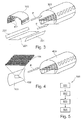
- Fig. 2a shows a portion of an outer skin 103 of an aircraft with a portion 200, which is shown enlarged.
- the enlarged portion shows a coarsely textured fabric 201, which is a thermal insulation unit, with a coarse fiber.
- the fabric 201 is formed to prevent capillary formation, thereby preventing the heat insulation unit 105 from being sucked up with water.
- the fabric 201 or thermal insulation unit has a plurality of strips 202, for example, substantially perpendicular to, for example, two connecting strips 203 and arranged substantially parallel to each other, wherein the strips 202 are sewn to the connecting strips 203 and thus the connecting strips 203, the strips 202 fix.
- the strips 202 and the connection strips 203 may be formed from a plastic or a natural material.
- the strips 202 can be fixed to the connection strip 203 by gluing or welding.
- the strips 202 and the connecting strips 203 can be attached by gluing or hooking to the outer skin 103.
- the fabric 201 can be attached to the outer skin 103 by sticking.
- a cutting of the fabric 201 can be carried out at the connection strip 203, without destroying the stability of the fabric 201 or so that fraying of the fabric during cutting can be avoided.
- FIG. 12 shows a cabin 102 and in a direction of the arrow P approximately at an arrow length distance thereof a car 102, which at the part of the outer skin 103 of FIG Fig. 2a with the roughly structured fabric 201, which functions as a thermal insulation unit, is mounted.
- the heat insulation unit or the fabric 201 is attached to the cabin by unwound over the outer skin 103 of the car 102, thereby falling down to a height of a floor on which the car 102 stands.
- Fig. 3 shows a part of an outer skin 103 with a cabin 102 attached to the part of the outer skin 103, and three tissue surfaces 201 acting as thermal insulation units.
- the part of the outer skin 103 with the cabin segments 102 and the fabric surfaces 201 may be assembled into a heat-insulated outer skin 303.
- the heat-insulating outer skin 303 is arranged in a direction of the arrows P at about an arrow-length distance from the part of the outer skin 103.
- Fig. 4 shows a part of an outer skin 103 with a portion 400, which is shown enlarged.
- the enlarged portion 400 shows a sound insulation unit 104 having a wave geometry for attenuating the sound, which is attached to the part of the outer skin 103.
- the sound insulation unit 104 may have, for example, the width of a frame and is attached to the outer skin 103 from the inside, for example by gluing.
- the part of the outer skin 103 can be mounted with further parts of an outer skin to a sound-insulated outer skin 403, for example by gluing, which is arranged approximately at an arrow distance of the arrow P from the part of the outer skin 103.
- Fig. 5 shows a flowchart of a method 500 for heat and sound insulation of an aircraft with the following steps: In a step 501 attaching the sound insulation unit to the outer skin of the Aircraft. In a further step 502, the thermal insulation unit is attached to the cabin of the aircraft. In step 503, the cabin is inserted into an aircraft fuselage. In step 504, the thermal insulation unit is pierced or cut at certain locations to pass holders or other cabin installations.
- the aircraft with an insulation system may have, for example, more than one cabin, more than one outer skin, more than one sound insulation unit, more than one thermal insulation unit, more than one air gap, and the thermal insulation unit more than one strip and more than one connection strip.
Landscapes
- Engineering & Computer Science (AREA)
- General Engineering & Computer Science (AREA)
- Mechanical Engineering (AREA)
- Aviation & Aerospace Engineering (AREA)
- Thermal Insulation (AREA)
- Soundproofing, Sound Blocking, And Sound Damping (AREA)
- Laminated Bodies (AREA)
Description
- Die Erfindung betrifft Isoliersysteme zur Wärme- und Schallisolierung. Insbesondere betrifft die Erfindung ein Luftfahrzeug mit einem Isolationssystem zur Wärme- und Schallisolierung. Ferner betrifft die Erfindung ein Verfahren zur Wärme- und Schallisolierung von einem Luftfahrzeug.
- Herkömmliche Isolierungen in einem Flugzeug bestehen aus einem watteähnlichen Isoliermaterial, das in Folie eingeschweißt wird. Das Einschweißen schützt das Isoliermaterial vor Nässe. Ohne die Einschweißfolie würde sich das Isoliermaterial mit Wasser vollsaugen was eine starke Gewichtserhöhung zur Folge hätte.
- Die Isolierung wird im Rumpf des Luftfahrzeugs montiert, bevor die Kabine und die anderen Systeme eingebaut werden. Damit die Isolierung an die Struktur des Flugzeugs passt, müssen für viele Stellen komplizierte Formen eingeschweißt werden (zum Beispiel an den Fenstern, Türen, etc.). Für die anschließende Montage der Systeme müssen die entsprechenden Halter zugänglich sein, also durch die Isolierung hindurchragen. Dazu werden Durchbrüche in der Folie vorgesehen, durch die man die Halterung dann erreichen kann. Diese Durchbrüche müssen anschließend aufwändig mit Klebern verschlossen werden, damit zum Beispiel keine Feuchtigkeit (Kondenswasser etc.) an das Isoliermaterial bzw. an dahinter befindliche Strukturen gelangen kann.
- Aus der
DE 10 2006 023 299 A1 und derWO 2007/131583 A1 ist eine Schallisolierung einer Flugzeugrumpfstruktur bekannt. - Die
DE 10 2007 008 986 A1 und dieWO 2008/101986 A1 zeigen einen Rumpf eines Luft- oder Raumfahrzeugs mit zumindest einem Schalenelement und einem Strukturelement und einem belüftbaren Zwischenraum zwischen dem Schalenelement und dem Strukturelement. -
FR 1 022 731 A -
WO 2005/095206 A1 beschreibt eine Schaumisolierung für Luftfahrzeuge mit einer faserartigen Schicht. - Es kann als Aufgabe der Erfindung gesehen werden, eine Wärme- und Schallisolierung in einem Transportmittel anzugeben, die einfach und flexibel einsetzbar ist.
- Es ist ein Luftfahrzeug mit einem Isolationssystem zur Wärme- und Schallisolierung sowie ein Verfahren zur Wärme- und Schallisolierung von einem Luftfahrzeug gemäß den Merkmalen der unabhängigen Ansprüche angegeben. Weiterbildungen der Erfindung werden durch die abhängigen Ansprüche verkörpert.
- Gemäß einem Ausführungsbeispiel der Erfindung ist ein Luftfahrzeug mit einem Isolationssystem zur Wärme- und Schallisolierung mit einer Kabine, einer Außenhaut, einer Schalldämmungseinheit und einer Wärmedämmungseinheit angegeben. Die Schalldämmungseinheit ist zum Schallisolieren des Luftfahrzeugs ausgeführt, die Wärmedämmungseinheit ist zum Wärmeisolieren des Luftfahrzeugs ausgeführt und die Schalldämmungseinheit und die Wärmedämmungseinheit sind zwischen der Kabine und der Außenhaut angeordnet.
- Ein derartiges Luftfahrzeug mit einem Isolationssystem ermöglicht es, die Herstellung und Montage der Wärme- und Schallisolierung zu vereinfachen, und die Arbeitszeit im Vergleich zur Herstellung und Montage einer integrierten einstückig ausgeführten Schall- und Wärmeisolierung zu verkürzen.
- Ein derartiges Isoliersystem weist den Vorteil auf, dass der Isolierungsaufwand reduziert werden kann, indem die Aufgaben Schallisolierung und Wärmeisolierung auf getrennte, optimal ausgelegte Komponenten, nämlich der Schalldämmungseinheit und der Wärmedämmungseinheit aufgeteilt werden. Dabei ist eine Voraussetzung, dass die Kabine als Ganzes in den Rumpf eingebaut wird.
- Die Wärmedämmungseinheit des Isolationssystems des Luftfahrzeugs besteht aus einem grob strukturierten Gewebe mit einer groben Faserung, die eine Kapillarbildung und damit ein Aufsaugen des Wassers bei Kontakt mit Wasser vermeidet. Somit muss die Wärmedämmungseinheit nicht eingeschweißt werden.
- Ein derartiges Isolationssystem ermöglicht es, dass auch bei Flugzeugen mit Carbonfaser-Kunststoff-Bauweise (CFK Bauweise) nur eine Schalldämmungseinheit und eine Wärmedämmungseinheit benötigt werden.
- Ein derartiges Isolationssystem im Luftfahrzeug ermöglicht es, dass das Gewebe der Wärmedämmungseinheit im Oberflurbereich, das heißt im oberen Bereich der Kabine, außerhalb des Rumpfes an der Kabine befestigt werden kann. Dort wo sich Fenster, Türen, Halter etc. befinden, kann die Wärmeisolierung einfach abgetrennt werden, ohne dass beispielsweise danach etwas geflickt werden muss.
- Die Schalldämmungseinheit des Isolationssystems des Luftfahrzeugs kann dabei als schallschluckendes Bauteil ausgeführt sein und großflächig an der Außenhaut des Rumpfes angebracht werden.
- Die Schalldämmungseinheit des Isolationssystems des Luftfahrzeugs kann geformt sein wie die schallschluckenden Wände eines Tonstudios. Durch die schalldämmende Geometrie und dem Material der Schalldämmungseinheit kann Schall absorbiert werden.
- Ein derartiges Isolationssystem eines Luftfahrzeugs ermöglicht eine bessere Wärme- und Schallisolierung durch die Trennung der Aufgaben der Wärme- und Schallisolierung in eine Schalldämmungseinheit und eine Wärmedämmungseinheit und die Verwendung geeigneter Materialien und Designs für die Wärmedämmungseinheit und die Schalldämmungseinheit.
- Das Isolationssystem des Luftfahrzeugs weist den Vorteil auf, dass eine einfache Herstellung der Isolierung, nämlich der Schalldämmungseinheit und der Wärmedämmungseinheit ermöglicht wird, da kein Einschweißen der Wärmedämmungseinheit mehr notwendig ist. Die Herstellung der Wärmeisolierung kann ähnlich der Herstellung eines Teppichs erfolgen und Wärmedämmung kann als Meterware produziert werden, da im Gegensatz zur eingeschweißten Wärmedämmungseinheit keine komplizierten Formen bei der Herstellung berücksichtigt werden müssen.
- Ferner ermöglicht ein derartiges Isolationssystem eines Luftfahrzeugs eine im Vergleich zu einer eingeschweißten Wärmedämmungseinheit einfache Montage da kein Flicken einer Einschweißfolie notwendig ist und die Wärmeisolierung von außerhalb des Rumpfes an der Kabine befestigbar ist.
- Durch ein derartiges Isolationssystem eines Luftfahrzeugs kann eine Zeitersparnis und eine Kostenersparnis aufgrund der einfachen Herstellung und der schnellen
- Montage des Isolationssystems im Vergleich zur Herstellung und Montage einer eingeschweißten Wärmedämmung ermöglicht werden.
- Ein derartiges Isolationssystem eines Luftfahrzeugs weist ferner den Vorteil auf, dass durch die Aufteilung der Aufgaben Wärme- und Schallisolierung eine Qualitätssteigerung erreicht werden kann.
- Gemäß einem weiteren Ausführungsbeispiel der Erfindung ist die Schalldämmung an der Außenhaut des Luftfahrzeugs angebracht, wobei die Wärmedämmungseinheit an der Kabine des Luftfahrzeugs angebracht ist.
- Gemäß einem weiteren Ausführungsbeispiel ist die Schalldämmung an die Außenhaut des Luftfahrzeugs von innen angeklebt, und die Wärmdämmungseinheit ist wie ein Fischernetz über die Kabine abgelegt.
- Gemäß einem weiteren Ausführungsbeispiel der Erfindung ist zwischen der Außenhaut und der Kabine ein Luftspalt vorhanden.
- Gemäß einem weiteren Ausführungsbeispiel der Erfindung ist zwischen der Wärmedämmungseinheit und der Schalldämmungseinheit ein Luftspalt vorhanden.
- Gemäß einem weiteren Ausführungsbeispiel der Erfindung ist die Schalldämmungseinheit an einer ersten Seite und die Wärmedämmungseinheit einer zweiten Seite der Kabine angebracht.
- Gemäß einem weiteren Ausführungsbeispiel der Erfindung ist die Schalldämmungseinheit an der Wärmedämmungseinheit angebracht, wobei die Kombination aus Schalldämmungseinheit und Wärmedämmungseinheit an der Kabine angebracht ist. Das bedeutet in anderen Worten, dass die Schalldämmungseinheit beispielsweise an der Wärmedämmungseinheit angebracht sein kann und dann die beiden verbundenen Dämmungseinheiten an der Kabine angebracht werden können. Die beiden verbundenen Dämmungseinheiten können beispielsweise im Bereich zwischen Kabine und Außenhaut oder an dem von der Außenwand abgewandten Teil der Kabine im Inneren der Kabine angebracht werden.
- Gemäß einem weiteren Ausführungsbeispiel der Erfindung sind die Schalldämmungseinheit und die Wärmedämmungseinheit aneinander angebracht an der Außenhaut angebracht. Das bedeutet in anderen Worten, dass die Schalldämmungseinheit an der Wärmedämmungseinheit angebracht werden kann und dann die verbundenen beiden Dämmungseinheiten an die Außenhaut in einem Bereich zwischen Kabine und Außenhaut angebracht werden können.
- Gemäß einem weiteren Ausführungsbeispiel der Erfindung ist die Schalldämmungseinheit an der Außenhaut von innen durch Kleben angebracht.
- Gemäß einem weiteren Ausführungsbeispiel der Erfindung ist die Schalldämmungseinheit aus einem Schalldämmmaterial aus der Gruppe bestehend aus Schaumgummi, Gummi, Polystyrol, einem schalldämmenden Kunststoff, einem schalldämmenden Naturwerkstoff, etc. gebildet.
- Gemäß einem weiteren Ausführungsbeispiel der Erfindung weist die Wärmedämmungseinheit eine Vielzahl von Streifen und einen Verbindungsstreifen auf, wobei der Verbindungsstreifen zum Fixieren der Streifen ausgeführt ist.
- Gemäß einem weiteren Ausführungsbeispiel der Erfindung sind die Streifen senkrecht zu dem Verbindungsstreifen angeordnet.
- Gemäß einem weiteren Ausführungsbeispiel der Erfindung sind die Streifen in regelmäßigen Abständen an dem Verbindungsstreifen fixiert.
- Die Streifen können durch Ankleben bzw. Anschweißen an den Verbindungsstreifen fixiert sein.
- Gemäß einem weiteren Ausführungsbeispiel der Erfindung sind die Streifen und die Verbindungsstreifen der Wärmedämmungseinheit durch Ankleben und/oder Einhaken an der Außenhaut des Luftfahrzeugs befestigt.
- Gemäß einem weiteren Ausführungsbeispiel der Erfindung sind die Streifen aus einem Material aus einer Gruppe bestehend aus Kunststoff, Naturwerkstoff, Polyurethan, Polycarbonat, Schaumstoff, Glasfaser, Glaswolle, Polyamid, glasfaserverstärkter Kunststoff (GFK) gebildet, wobei der Verbindungsstreifen aus einem Material aus der Gruppe bestehend aus Kunststoff, Naturwerkstoff, Polyurethan, Polycarbonat, Schaumstoff, Glasfaser, Glaswolle, Polyamid, glasfaserverstärkter Kunststoff (GFK) gebildet ist.
- Gemäß einem weiteren Ausführungsbeispiel der Erfindung ist die Wärmedämmungseinheit zum Auftrennen, ohne dass hierdurch ein Ausfransen der Wärmedämmungseinheit bewirkt wird, ausgeführt. Ein Auftrennen ohne Ausfransen der Wärmedämmungseinheit wird dadurch ermöglicht, dass die Streifen der Wärmedämmungseinheit bei der Auftrennung nicht beschädigt werden, sondern nur verschoben werden. Ein Zuschneiden des Gewebes der Wärmedämmungseinheit kann bei den Verbindungsstreifen erfolgen, so dass die Stabilität des Gewebes nicht verringert wird bzw. ein Ausfransen des Gewebes beim Zuschneiden vermieden werden kann.
- Gemäß einem weiteren Ausführungsbeispiel der Erfindung ist ein Verfahren zur Wärme- und Schallisolierung von einem Luftfahrzeug angegeben mit einem ersten Schritt zum Anbringen einer Schalldämmungseinheit und einer Wärmedämmungseinheit zwischen einer Kabine und einer Außenhaut des Luftfahrzeugs.
- Gemäß einem weiteren Ausführungsbeispiel der Erfindung weist das Verfahren weiterhin das Anbringen einer Schalldämmungseinheit an der Außenhaut des Luftfahrzeugs sowie das Anbringen einer Wärmedämmungseinheit an der Kabine des Luftfahrzeugs auf, wobei die Wärmedämmungseinheit aus einem grobstrukturierten Gewebe mit einer groben Faserung zum Vermeiden einer Kapillar-bildung gebildet ist und damit ein Aufsaugen der Wärmedämmungseinheit mit Wasser vermeidet. Gemäß einem weiteren Ausführungsbeispiel der Erfindung weist das Verfahren weiterhin das Einführen der Kabine in einen Luftfahrzeugrumpf und das Durchbohren oder Durchtrennen der Wärmedämmungseinheit an bestimmten Stellen zum Hindurchführen von Haltern oder anderer Einbauten für die Kabine auf.
- Es ist insbesondere zu beachten, dass die hier und im Folgenden im Hinblick auf das Luftfahrzeug mit dem Isolationssystem beschriebenen Merkmale auch in dem Verfahren implementierbar sind und umgekehrt.
- Diese und andere Aspekte der Erfindung werden durch die Bezugnahme auf die hiernach beschriebenen beispielhaften Ausführungsformen erläutert und verdeutlicht.
-
- Fig. 1
- zeigt ein Luftfahrzeug mit einem Isolationssystem zur Wärme- und Schallisolierung gemäß einem Ausführungsbeispiel der Erfindung.
- Fig. 2a
- zeigt eine Außenhaut mit einer Wärmedämmungseinheit in Form eines Gewebes gemäß einem Ausführungsbeispiel der Erfindung.
- Fig. 2b
- zeigt die Außenhaut mit der Wärmedämmungseinheit der
Fig. 2a und eine einzelne sowie an der Außenhaut angeordnete Kabine gemäß einem Ausführungsbeispiel der Erfindung. - Fig. 3
- zeigt ein Segment einer Außenhaut mit einer Kabine sowie Gewebeflächen von Wärmedämmungseinheiten und ein Flugzeugrumpfsegment gemäß einem Ausführungsbeispiel der Erfindung.
- Fig. 4
- zeigt eine Außenhaut mit einer Schalldämmungseinheit und ein Flugzeugrumpfsegment gemäß einem Ausführungsbeispiel der Erfindung.
- Fig. 5
- zeigt ein Flussdiagramm eines Verfahrens zur Wärme- und Schallisolierung von einem Luftfahrzeug gemäß einem Ausführungsbeispiel der Erfindung.
- Im Folgenden werden unter Bezugnahme auf die beigefügten Figuren Ausführungsbeispiele der Erfindung beschrieben.
- Die Darstellung in den Figuren ist schematisch und nicht maßstäblich. In den folgenden Figuren werden für gleiche oder ähnliche Elemente die gleichen Bezugszeichen verwendet.
-
Fig. 1 zeigt eine Seitenansicht eines Luftfahrzeugs 100 mit einer Schnittlinie A-A quer durch den Flugzeugrumpf. - Gemäß der Schnittlinie A-A zeigt die
Figur 1 weiterhin einen Querschnitt A-A eines Isolationssystems 101 mit einer kreisförmigen Form. - Das Isolationssystem 101 weist eine innen angeordnete kreisförmigen Kabine 102, eine daran vom Mittelpunkt des kreisförmigen Isolationssystems 101 gesehen außen angeordneten Wärmedämmungseinheit 105, einen daran anschließenden Luftspalt 106 und eine daran anschließend eine Schalldämmungseinheit 104 auf, die an einer kreisförmigen Außenhaut 103 des Luftfahrzeugs 100 angebracht ist.
- Die Schalldämmungseinheit 104 ist zum Schallisolieren des Luftfahrzeugs 100 ausgeführt. Die Wärmedämmungseinheit 105 ist zum Wärmeisolieren des Luftfahrzeugs 100 ausgeführt.
-
Fig. 2a zeigt einen Teil einer Außenhaut 103 eines Luftfahrzeugs mit einem Abschnitt 200, der vergrößert dargestellt ist. Der vergrößerte Abschnitt zeigt ein grob strukturiertes Gewebe 201, das eine Wärmedämmungseinheit darstellt, mit einer groben Faserung. Das Gewebe 201 ist zum Vermeiden einer Kapillarbildung gebildet und verhindert damit ein Aufsaugen der Wärmedämmungseinheit 105 mit Wasser. - Das Gewebe 201 bzw. die Wärmedämmungseinheit weist eine Vielzahl von Streifen 202 auf, die beispielsweise im Wesentlichen rechtwinklig zu beispielsweise zwei Verbindungsstreifen 203 und im Wesentlichen zueinander parallel angeordnet sind, wobei die Streifen 202 an die Verbindungsstreifen 203 angenäht sind und somit die Verbindungsstreifen 203 die Streifen 202 fixieren.
- Die Streifen 202 und die Verbindungsstreifen 203 können aus einem Kunststoff bzw. einem Naturwerkstoff gebildet sein. Die Streifen 202 können durch Ankleben bzw. Anschweißen an den Verbindungsstreifen 203 fixiert werden.
- Die Streifen 202 bzw. die Verbindungsstreifen 203 können durch Ankleben bzw. Einhaken an der Außenhaut 103 befestigt werden. Somit kann das Gewebe 201 durch Ankleben bzw. Einhaken an der Außenhaut 103 befestigt werden.
- Ein Zuschneiden des Gewebes 201 kann bei den Verbindungsstreifen 203 erfolgen, ohne dass die Stabilität des Gewebes 201 zerstört wird bzw. so dass ein Ausfransen des Gewebes beim Zuschneiden vermieden werden kann.
-
Fig. 2b zeigt eine Kabine 102 und in einer Richtung des Pfeils P in etwa einem Pfeillängenabstand davon eine Kabine 102, die an dem Teil der Außenhaut 103 derFig. 2a mit dem grob strukturieren Gewebe 201, das als Wärmedämmungseinheit fungiert, montiert ist. - Die Wärmedämmungseinheit bzw. das Gewebe 201 wird an die Kabine angebracht indem es über die Außenhaut 103 der Kabine 102 abgewickelt und fällt dabei bis zu einer Höhe eines Fußbodens, auf dem die Kabine 102 steht, herunter.
-
Fig. 3 zeigt einen Teil einer Außenhaut 103 mit einer Kabine 102, die an dem Teil der Außenhaut 103 angebracht ist, und drei Gewebeflächen 201, die als Wärmedämmungseinheiten fungieren. Der Teil der Außenhaut 103 mit den Kabinensegmenten 102 und die Gewebeflächen 201 können zu einer wärmeisolierten Außenhaut 303 montiert werden. Die wärmeisolierte Außenhaut 303 ist in einer Richtung der Pfeile P in etwa einem Pfeillängenabstand von dem Teil der Außenhaut 103 angeordnet. -
Fig. 4 zeigt einen Teil einer Außenhaut 103 mit einem Abschnitt 400, der vergrößert dargestellt ist. Der vergrößerte Abschnitt 400 zeigt eine Schalldämmungseinheit 104 mit einer Wellengeometrie zum Dämpfen des Schalls, die an dem Teil der Außenhaut 103 angebracht ist. Die Schalldämmungseinheit 104 kann dabei beispielsweise die Breite eines Spanten aufweisen und ist an der Außenhaut 103 von innen beispielsweise durch Kleben angebracht. - Der Teil der Außenhaut 103 ist mit weiteren Teilen einer Außenhaut zu einer schallisolierten Außenhaut 403 montierbar, beispielsweise durch Kleben, die in etwa einem Pfeillängenabstand des Pfeils P von dem Teil der Außenhaut 103 angeordnet ist.
-
Fig. 5 zeigt ein Flussdiagramm eines Verfahrens 500 zur Wärme- und Schallisolierung von einem Luftfahrzeug mit den folgenden Schritten: In einem Schritt 501 erfolgt ein Anbringen der Schalldämmungseinheit an der Außenhaut des Luftfahrzeugs. In einem weiteren Schritt 502 erfolgt ein Anbringen der Wärmedämmungseinheit an der Kabine des Luftfahrzeugs. In Schritt 503 wird die Kabine in einen Luftfahrzeugrumpf eingeführt. In Schritt 504 wird die Wärmedämmungseinheit an bestimmten Stellen durchbohrt oder durchtrennt, um Halter oder andere Einbauten für die Kabine hindurchzuführen. - Ergänzend ist darauf hinzuweisen, dass "umfassend" oder "aufweisend" keine anderen Elemente oder Schritte ausschließt und "eine" oder "ein" keine Vielzahl ausschließt. Insbesondere kann das Luftfahrzeug mit einem Isolationssystem beispielsweise mehr als eine Kabine, mehr als eine Außenhaut, mehr als eine Schalldämmungseinheit, mehr als eine Wärmedämmungseinheit, mehr als einen Luftspalt sowie die Wärmedämmungseinheit mehr als einen Streifen und mehr als einen Verbindungsstreifen aufweisen.
- Ferner sei darauf hingewiesen, dass Merkmale oder Schritte, die mit Verweis auf eines der obigen Ausführungsbeispiele beschrieben worden sind, auch in Kombination mit anderen Merkmalen oder Schritten anderer oben beschriebener Ausführungsbeispiele verwendet werden können, sofern sie den Schutzbereich der Patentansprüche nicht übersteigen. Bezugszeichen in den Ansprüchen sind nicht als Einschränkung anzusehen.
Claims (13)
- Luftfahrzeug (100) mit einem Iso lationssystem (101) zur Wärme- und Schallisolierung, das Luftfahrzeug (100) aufweisend:eine Kabine (102);eine Außenhaut (103);eine Schalldämmungseinheit (104);eine Wärmedämmungseinheit (105);wobei die Schalldämmungseinheit (104) zum Schallisolieren des Luftfahrzeugs (100) ausgeführt ist;wobei die Wärmedämmungseinheit (105) zum Wärmeisolieren des Luftfahrzeugs (100) ausgeführt ist;wobei die Schalldämmungseinheit (104) und die Wärmedämmungseinheit (105) zwischen der Kabine (102) und der Außenhaut (103) angeordnet sind; dadurch gekennzeichnet, daßdie Wärmedämmungseinheit (105) aus einem grobstrukturierten Gewebe (201) mit einer groben Faserung zum Vermeiden einer Kapillarbildung gebildet ist und damit ein Aufsaugen der Wärmedämmungseinheit (105) mit Wasser vermeidet.
- Luftfahrzeug (100) nach Anspruch 1
wobei die Schalldämmungseinheit (104) an der Außenhaut (103) des Luftfahrzeugs (100) angebracht ist;
wobei die Wärmedämmungseinheit (105) an der Kabine (102) des Luftfahrzeugs (100) angebracht ist. - Luftfahrzeug (100) nach einem der vorhergehenden Ansprüche,
wobei zwischen der Außenhaut (103) und der Kabine (102) ein Luftspalt (106) vorhanden ist. - Luftfahrzeug (100) nach einem der Ansprüche 1 oder 3,
wobei die Schalldämmungseinheit (104) an der Wärmedämmungseinheit (105) angebracht ist; und
wobei die Kombination aus Schalldämmungseinheit (104) und Wärmedämmungseinheit (105) an der Kabine (102) angebracht ist. - Luftfahrzeug (100) nach einem der Ansprüche 1 oder 3,
wobei die Schalldämmungseinheit (104) und die Wärmedämmungseinheit (105) aneinander angebracht an der Außenhaut (103) angebracht sind. - Luftfahrzeug (100) nach einem der vorhergehenden Ansprüche,
wobei die Schalldämmungseinheit (104) aus einem schalldämmenden Material aus einer Gruppe bestehend aus Schaumgummi, Gummi, Polystyrol, schalldämmenden Kunststoff und schalldämmenden Naturwerkstoff gebildet ist, - Luftfahrzeug (100) nach einem der vorhergehenden Ansprüche,
wobei die Wärmedämmungseinheit (105) aufweist:eine Vielzahl von Streifen (202);einen Verbindungsstreifen (203);wobei der Verbindungsstreifen (203) zum Fixieren der Streifen (202) ausgeführt ist. - Luftfahrzeug (100) nach Anspruch 7,
wobei die Streifen (202) senkrecht zu dem Verbindungsstreifen (203) angeordnet sind. - Luftfahrzeug (100) nach einem der Ansprüche 7 oder 8,
wobei die Streifen (202) in regelmäßigen Abständen an den Verbindungsstreifen (203) fixiert sind. - Luftfahrzeug (100) nach einem der Ansprüche 7 bis 9,
wobei die Streifen (202) aus einem Material aus einer. Gruppe bestehend aus Kunststoff, Naturwerkstoff, Polyurethan, Polycarbonat, Schaumstoff, Glasfaser, Glaswolle, Polyamid, glasfaserverstärkter Kunststoff (GFK) gebildet sind;
wobei der Verbindungsstreifen (203) aus einem Material aus einer Gruppe bestehend aus Kunststoff, Naturwerkstoff, Polyurethan, Polycarbonat, Schaumstoff, Glasfaser, Glaswolle, Polyamid, glasfaserverstärkter Kunststoff (GFK) gebildet ist. - Luftfahrzeug (100) nach einem der vorhergehenden Ansprüche,
wobei die Wärmedämmungseinheit (105) zum Auftrennen, ohne dass hierdurch ein Ausfransen der Wärmedämmungseinheit (105) bewirkt wird, ausgeführt ist. - Verfahren (500) zur Wärme- und Schallisolierung von einem Luftfahrzeug (100), das Verfahren (500) aufweisend den Schritt:Anbringen einer Schalldämmungseinheit (104) und einer Wärmedämmungseinheit (105) zwischen einer Kabine (102) und einer Außenhaut (103) des Luftfahrzeugs (100, 501);wobei die Wärmedämmungseinheit (105) aus einem grobstrukturierten Gewebe (201) mit einer groben Faserung zum Vermeiden einer Kapillarbildung gebildet ist und damit ein Aufsaugen der Wärmedämmungseinheit (105) mit Wasser vermeidet.
- Verfahren (500) nach Anspruch 12, weiterhin aufweisend die Schritte:Anbringen einer Schalldämmungseinheit (104) an der Außenhaut (103) des Luftfahrzeugs (100, 502);
Anbringen einer Wärmedämmungseinheit (105) an der Kabine (102) des Luftfahrzeugs (100, 503).
Applications Claiming Priority (3)
| Application Number | Priority Date | Filing Date | Title |
|---|---|---|---|
| US16457609P | 2009-03-30 | 2009-03-30 | |
| DE102009015590A DE102009015590A1 (de) | 2009-03-30 | 2009-03-30 | Luftfahrzeug mit einem Isolierungssystem zur Wärme- und Schallisolierung |
| PCT/EP2010/052294 WO2010112270A1 (de) | 2009-03-30 | 2010-02-23 | Luftfahrzeug mit einem isolierungssystem zur wärme- und schallisolierung |
Publications (2)
| Publication Number | Publication Date |
|---|---|
| EP2414229A1 EP2414229A1 (de) | 2012-02-08 |
| EP2414229B1 true EP2414229B1 (de) | 2013-08-21 |
Family
ID=42674912
Family Applications (1)
| Application Number | Title | Priority Date | Filing Date |
|---|---|---|---|
| EP10704838.1A Not-in-force EP2414229B1 (de) | 2009-03-30 | 2010-02-23 | Luftfahrzeug mit einem isolierungssystem zur wärme- und schallisolierung |
Country Status (7)
| Country | Link |
|---|---|
| US (1) | US9073621B2 (de) |
| EP (1) | EP2414229B1 (de) |
| JP (1) | JP2012521924A (de) |
| CN (1) | CN102365201A (de) |
| CA (1) | CA2755378A1 (de) |
| DE (1) | DE102009015590A1 (de) |
| WO (1) | WO2010112270A1 (de) |
Families Citing this family (12)
| Publication number | Priority date | Publication date | Assignee | Title |
|---|---|---|---|---|
| US9045216B2 (en) * | 2008-01-18 | 2015-06-02 | The Boeing Company | Flight vehicle fairing having vibration-damping blankets |
| US9868530B2 (en) * | 2012-03-23 | 2018-01-16 | B/E Aerospace, Inc. | Acoustically and thermally insulated galley shell |
| CN103496249B (zh) * | 2013-09-29 | 2015-07-29 | 湖北三江航天红阳机电有限公司 | 一种飞行器应变隔离层的制备方法 |
| CN103640685A (zh) * | 2013-12-29 | 2014-03-19 | 陈俞任 | 铝网龙骨玻璃钢防弹隐形飞机 |
| FR3019599B1 (fr) * | 2014-04-08 | 2016-05-06 | Aircelle Sa | Agencement de fixation pour panneau de protection thermique |
| CN104210645B (zh) * | 2014-06-10 | 2018-11-30 | 中国商用飞机有限责任公司 | 飞机隔声壁板 |
| US11821409B2 (en) * | 2015-01-06 | 2023-11-21 | The Boeing Company | Environmental aspect control assembly |
| US9725155B2 (en) * | 2015-12-30 | 2017-08-08 | General Electric Company | Method and system for open rotor engine fuselage protection |
| EP3301018A1 (de) * | 2016-09-30 | 2018-04-04 | Airbus Operations GmbH | System zum antreiben und führen einer multifunktionalen hinterkantensteuerungsoberfläche an einem flugzeug |
| FR3061130B1 (fr) * | 2016-12-22 | 2021-07-02 | Airbus Operations Sas | Module d'isolation thermophonique pour aeronef comprenant un matelas et une structure porteuse, et procede d'isolation thermophonique d'un aeronef au moyen d'un tel module |
| JP6688265B2 (ja) * | 2017-08-28 | 2020-04-28 | ニチアス株式会社 | 輸送機器用断熱吸音材 |
| CN116142487B (zh) * | 2023-02-27 | 2025-07-25 | 哈尔滨工业大学 | 一种火星多旋翼飞行器机身箱体结构 |
Family Cites Families (24)
| Publication number | Priority date | Publication date | Assignee | Title |
|---|---|---|---|---|
| US2362951A (en) * | 1941-04-08 | 1944-11-14 | Vickers Armstrongs Ltd | Pressure-tight cabin for aircraft |
| US2540331A (en) * | 1945-06-18 | 1951-02-06 | Rudolf F Hlavaty | Insulation |
| FR1022731A (fr) | 1950-08-01 | 1953-03-09 | Sncase | Procédé d'insonorisation et d'isolation thermique à structures absorbantes multiples et structures en permettant la mise en oeuvre |
| FR1490522A (fr) | 1966-04-19 | 1967-08-04 | Dassault Avions | Procédé et matériel d'insonorisation pour véhicules |
| JPS484001Y1 (de) * | 1967-01-18 | 1973-02-01 | ||
| US3867244A (en) | 1971-12-22 | 1975-02-18 | Boeing Co | Insulation and condensation control blanket |
| US4291851A (en) | 1978-12-18 | 1981-09-29 | The Boeing Company | Thermal insulation for aircraft fuselage |
| JPS57153525U (de) * | 1981-03-25 | 1982-09-27 | ||
| DE3805269A1 (de) * | 1988-02-19 | 1989-08-31 | Gruenzweig & Hartmann | Daemmatte fuer koerper mit wenigstens bereichsweise gekruemmter oberflaeche, insbesondere fuer rohre, sowie ihre verwendung |
| JP3629416B2 (ja) * | 2000-08-30 | 2005-03-16 | 住友金属建材株式会社 | 遮音壁パネル |
| JP2003316362A (ja) * | 2002-04-19 | 2003-11-07 | Ngk Spark Plug Co Ltd | 防音材及びその防音材の使用方法 |
| EP1378444B1 (de) * | 2002-07-01 | 2011-01-05 | Barry Controls Corp. | Zwei-Ton Schwingungsdämpfer |
| JP2004317999A (ja) * | 2003-04-21 | 2004-11-11 | Hitachi Ltd | 断熱遮音装置 |
| DE102004001049B4 (de) * | 2004-01-05 | 2009-12-10 | Airbus Deutschland Gmbh | Isolierpaket-Anordnung zur Innenisolierung eines Flugzeugrumpfes |
| DE102004001078B8 (de) * | 2004-01-05 | 2013-06-13 | Airbus Operations Gmbh | Flugzeugrumpf |
| US7040575B2 (en) * | 2004-03-29 | 2006-05-09 | The Boeing Company | Foam composite insulation for aircraft |
| US20060222837A1 (en) * | 2005-03-31 | 2006-10-05 | The Boeing Company | Multi-axial laminate composite structures and methods of forming the same |
| DE102005016654B4 (de) | 2005-04-12 | 2008-11-20 | Airbus Deutschland Gmbh | Sandwichelement zur schallabsorbierenden Innenverkleidung von Verkehrsmitteln, insbesondere zur schallabsorbierenden Innenverkleidung von Luftfahrzeugen |
| DE102005016653B4 (de) | 2005-04-12 | 2008-10-02 | Airbus Deutschland Gmbh | Sandwichelement zur schallabsorbierenden Innenverkleidung von Verkehrsmitteln, insbesondere zur schallabsorbierenden Innenverkleidung von Rumpfzellen von Luftfahrzeugen |
| DE102006023209A1 (de) * | 2006-05-17 | 2007-11-22 | Airbus Deutschland Gmbh | Isolierung einer Flugzeugrumpfstruktur |
| DE102007008986A1 (de) | 2007-02-23 | 2008-08-28 | Airbus Deutschland Gmbh | Rumpf eines Luft-oder Raumfahrzeugs, und ein entsprechendes Luft-oder Raumfahrzeug |
| BRPI0807567A2 (pt) | 2007-02-23 | 2014-07-01 | Airbus Operations Gmbh | Fuselagem de aeronave ou espaçonave e método de isolar ativamente tal fuselagem |
| DE102008062701A1 (de) | 2008-12-17 | 2010-07-01 | Airbus Deutschland Gmbh | Flugzeugkabinenpaneel mit Kerntaschen zur Schallabsorption |
| DE102008063923A1 (de) | 2008-12-19 | 2010-06-24 | Airbus Deutschland Gmbh | Mehrschichtplatte zur Schalldämmung |
-
2009
- 2009-03-30 DE DE102009015590A patent/DE102009015590A1/de not_active Withdrawn
-
2010
- 2010-02-23 JP JP2012502531A patent/JP2012521924A/ja active Pending
- 2010-02-23 CN CN2010800142746A patent/CN102365201A/zh active Pending
- 2010-02-23 WO PCT/EP2010/052294 patent/WO2010112270A1/de not_active Ceased
- 2010-02-23 CA CA2755378A patent/CA2755378A1/en not_active Abandoned
- 2010-02-23 EP EP10704838.1A patent/EP2414229B1/de not_active Not-in-force
- 2010-02-23 US US13/258,786 patent/US9073621B2/en not_active Expired - Fee Related
Also Published As
| Publication number | Publication date |
|---|---|
| DE102009015590A1 (de) | 2010-10-07 |
| US20120012698A1 (en) | 2012-01-19 |
| JP2012521924A (ja) | 2012-09-20 |
| CN102365201A (zh) | 2012-02-29 |
| WO2010112270A1 (de) | 2010-10-07 |
| CA2755378A1 (en) | 2010-10-07 |
| WO2010112270A4 (de) | 2011-01-06 |
| EP2414229A1 (de) | 2012-02-08 |
| US9073621B2 (en) | 2015-07-07 |
Similar Documents
| Publication | Publication Date | Title |
|---|---|---|
| WO2010112270A1 (de) | Luftfahrzeug mit einem isolierungssystem zur wärme- und schallisolierung | |
| EP2358589B1 (de) | Flugzeugkabinenpaneel zur schallreduktion | |
| EP0687611B1 (de) | Verfahren für die Herstellung von Fahrzeugstrukturen | |
| DE102008017357A1 (de) | Akustisch optimiertes Kabinenwandelement | |
| DE102008063923A1 (de) | Mehrschichtplatte zur Schalldämmung | |
| DE4340951A1 (de) | Einstückiges Triebwerkeinlaß-Schallrohr | |
| DE102007008988A1 (de) | Rumpf eines Luft-oder Raumfahrzeugs und ein entsprechendes Luft-oder Raumfahrzeug | |
| WO2011017727A2 (de) | Verfahren zur herstellung eines - als sandwichkonstruktion ausgebildeten - hohlkörpers | |
| DE102006012953A1 (de) | Drainage-Vorrichtung, Flugzeug und Verfahren zum Abführen eines zwischen einer Aussenhaut und einer Innenverkleidung eines Flugzeugs vorhandenen Fluids | |
| DE102009030037A1 (de) | Isolierungspaket für die Isolierung einer Kabine eines Fahrzeugs | |
| WO2010015503A1 (de) | Isolationsaufbau zum thermischen und akustischen isolieren eines luftfahrzeugs | |
| EP3680509A1 (de) | Sandwichplatte mit akustischen dämpfungseigenschaften | |
| EP2311722A1 (de) | Isolationsanordnung | |
| DE102010064100A1 (de) | Trennwand für eine Flugzeugkabine und Flugzeug | |
| EP2925520A1 (de) | Mehrlagige gebäudemembran mit schaumkern | |
| DE102012010463A1 (de) | Rohbaustruktur für ein Kraftfahrzeug und Verfahren zum Herstellen einer solchen Rohbaustruktur | |
| DE202019103668U1 (de) | Schallabschirmungsmatte, Schallabschirmungssystem und Gleisoberbaumaschine | |
| DE69910051T2 (de) | Bodenplatte für fahrzeugboden | |
| DE102013021403A1 (de) | Unterbodenaussteifungs- und Verkleidungsmodul, Herstellverfahren sowie Kraftfahrzeug-Unterboden und Montageverfahren | |
| DE102007061429B4 (de) | Rumpfstruktur | |
| EP1917185B1 (de) | Schalldämmelement für verkehrsmittel, insbesondere für luftfahrzeuge | |
| EP1717143B1 (de) | Schalldämmmaterial für die Dämmung in Flugzeugen | |
| DE102020002099A1 (de) | Vakuumisolationspaneel mit mindestens einer Stützschicht, Innenausstattungspaneel mit dem Vakuumisolationspaneel sowie Flugzeug mit dem Innenaustattungspaneel und/oder dem Vakuumisolationspaneel | |
| DE102019132292B3 (de) | Strukturverstärkendes Frachtraummodul | |
| DE102014215661A1 (de) | Flugzeuginnenverkleidungsbauteil, Verfahren zur Herstellung eines Flugzeuginnenverkleidungsbauteils und Flugzeugbaugruppe |
Legal Events
| Date | Code | Title | Description |
|---|---|---|---|
| PUAI | Public reference made under article 153(3) epc to a published international application that has entered the european phase |
Free format text: ORIGINAL CODE: 0009012 |
|
| 17P | Request for examination filed |
Effective date: 20110919 |
|
| AK | Designated contracting states |
Kind code of ref document: A1 Designated state(s): AT BE BG CH CY CZ DE DK EE ES FI FR GB GR HR HU IE IS IT LI LT LU LV MC MK MT NL NO PL PT RO SE SI SK SM TR |
|
| DAX | Request for extension of the european patent (deleted) | ||
| GRAP | Despatch of communication of intention to grant a patent |
Free format text: ORIGINAL CODE: EPIDOSNIGR1 |
|
| INTG | Intention to grant announced |
Effective date: 20130405 |
|
| GRAS | Grant fee paid |
Free format text: ORIGINAL CODE: EPIDOSNIGR3 |
|
| GRAA | (expected) grant |
Free format text: ORIGINAL CODE: 0009210 |
|
| AK | Designated contracting states |
Kind code of ref document: B1 Designated state(s): AT BE BG CH CY CZ DE DK EE ES FI FR GB GR HR HU IE IS IT LI LT LU LV MC MK MT NL NO PL PT RO SE SI SK SM TR |
|
| REG | Reference to a national code |
Ref country code: GB Ref legal event code: FG4D Free format text: NOT ENGLISH |
|
| REG | Reference to a national code |
Ref country code: CH Ref legal event code: EP |
|
| REG | Reference to a national code |
Ref country code: AT Ref legal event code: REF Ref document number: 627892 Country of ref document: AT Kind code of ref document: T Effective date: 20130915 |
|
| REG | Reference to a national code |
Ref country code: IE Ref legal event code: FG4D Free format text: LANGUAGE OF EP DOCUMENT: GERMAN |
|
| REG | Reference to a national code |
Ref country code: DE Ref legal event code: R096 Ref document number: 502010004442 Country of ref document: DE Effective date: 20131017 |
|
| REG | Reference to a national code |
Ref country code: NL Ref legal event code: VDEP Effective date: 20130821 |
|
| REG | Reference to a national code |
Ref country code: LT Ref legal event code: MG4D |
|
| PG25 | Lapsed in a contracting state [announced via postgrant information from national office to epo] |
Ref country code: SE Free format text: LAPSE BECAUSE OF FAILURE TO SUBMIT A TRANSLATION OF THE DESCRIPTION OR TO PAY THE FEE WITHIN THE PRESCRIBED TIME-LIMIT Effective date: 20130821 Ref country code: CY Free format text: LAPSE BECAUSE OF FAILURE TO SUBMIT A TRANSLATION OF THE DESCRIPTION OR TO PAY THE FEE WITHIN THE PRESCRIBED TIME-LIMIT Effective date: 20130807 Ref country code: LT Free format text: LAPSE BECAUSE OF FAILURE TO SUBMIT A TRANSLATION OF THE DESCRIPTION OR TO PAY THE FEE WITHIN THE PRESCRIBED TIME-LIMIT Effective date: 20130821 Ref country code: NO Free format text: LAPSE BECAUSE OF FAILURE TO SUBMIT A TRANSLATION OF THE DESCRIPTION OR TO PAY THE FEE WITHIN THE PRESCRIBED TIME-LIMIT Effective date: 20131121 Ref country code: PT Free format text: LAPSE BECAUSE OF FAILURE TO SUBMIT A TRANSLATION OF THE DESCRIPTION OR TO PAY THE FEE WITHIN THE PRESCRIBED TIME-LIMIT Effective date: 20131223 Ref country code: HR Free format text: LAPSE BECAUSE OF FAILURE TO SUBMIT A TRANSLATION OF THE DESCRIPTION OR TO PAY THE FEE WITHIN THE PRESCRIBED TIME-LIMIT Effective date: 20130821 Ref country code: IS Free format text: LAPSE BECAUSE OF FAILURE TO SUBMIT A TRANSLATION OF THE DESCRIPTION OR TO PAY THE FEE WITHIN THE PRESCRIBED TIME-LIMIT Effective date: 20131221 |
|
| PG25 | Lapsed in a contracting state [announced via postgrant information from national office to epo] |
Ref country code: LV Free format text: LAPSE BECAUSE OF FAILURE TO SUBMIT A TRANSLATION OF THE DESCRIPTION OR TO PAY THE FEE WITHIN THE PRESCRIBED TIME-LIMIT Effective date: 20130821 Ref country code: GR Free format text: LAPSE BECAUSE OF FAILURE TO SUBMIT A TRANSLATION OF THE DESCRIPTION OR TO PAY THE FEE WITHIN THE PRESCRIBED TIME-LIMIT Effective date: 20131122 Ref country code: FI Free format text: LAPSE BECAUSE OF FAILURE TO SUBMIT A TRANSLATION OF THE DESCRIPTION OR TO PAY THE FEE WITHIN THE PRESCRIBED TIME-LIMIT Effective date: 20130821 Ref country code: PL Free format text: LAPSE BECAUSE OF FAILURE TO SUBMIT A TRANSLATION OF THE DESCRIPTION OR TO PAY THE FEE WITHIN THE PRESCRIBED TIME-LIMIT Effective date: 20130821 Ref country code: SI Free format text: LAPSE BECAUSE OF FAILURE TO SUBMIT A TRANSLATION OF THE DESCRIPTION OR TO PAY THE FEE WITHIN THE PRESCRIBED TIME-LIMIT Effective date: 20130821 |
|
| PG25 | Lapsed in a contracting state [announced via postgrant information from national office to epo] |
Ref country code: CY Free format text: LAPSE BECAUSE OF FAILURE TO SUBMIT A TRANSLATION OF THE DESCRIPTION OR TO PAY THE FEE WITHIN THE PRESCRIBED TIME-LIMIT Effective date: 20130821 |
|
| PG25 | Lapsed in a contracting state [announced via postgrant information from national office to epo] |
Ref country code: SK Free format text: LAPSE BECAUSE OF FAILURE TO SUBMIT A TRANSLATION OF THE DESCRIPTION OR TO PAY THE FEE WITHIN THE PRESCRIBED TIME-LIMIT Effective date: 20130821 Ref country code: EE Free format text: LAPSE BECAUSE OF FAILURE TO SUBMIT A TRANSLATION OF THE DESCRIPTION OR TO PAY THE FEE WITHIN THE PRESCRIBED TIME-LIMIT Effective date: 20130821 Ref country code: NL Free format text: LAPSE BECAUSE OF FAILURE TO SUBMIT A TRANSLATION OF THE DESCRIPTION OR TO PAY THE FEE WITHIN THE PRESCRIBED TIME-LIMIT Effective date: 20130821 Ref country code: RO Free format text: LAPSE BECAUSE OF FAILURE TO SUBMIT A TRANSLATION OF THE DESCRIPTION OR TO PAY THE FEE WITHIN THE PRESCRIBED TIME-LIMIT Effective date: 20130821 Ref country code: CZ Free format text: LAPSE BECAUSE OF FAILURE TO SUBMIT A TRANSLATION OF THE DESCRIPTION OR TO PAY THE FEE WITHIN THE PRESCRIBED TIME-LIMIT Effective date: 20130821 Ref country code: DK Free format text: LAPSE BECAUSE OF FAILURE TO SUBMIT A TRANSLATION OF THE DESCRIPTION OR TO PAY THE FEE WITHIN THE PRESCRIBED TIME-LIMIT Effective date: 20130821 |
|
| PG25 | Lapsed in a contracting state [announced via postgrant information from national office to epo] |
Ref country code: IT Free format text: LAPSE BECAUSE OF FAILURE TO SUBMIT A TRANSLATION OF THE DESCRIPTION OR TO PAY THE FEE WITHIN THE PRESCRIBED TIME-LIMIT Effective date: 20130821 Ref country code: ES Free format text: LAPSE BECAUSE OF FAILURE TO SUBMIT A TRANSLATION OF THE DESCRIPTION OR TO PAY THE FEE WITHIN THE PRESCRIBED TIME-LIMIT Effective date: 20130821 |
|
| PLBE | No opposition filed within time limit |
Free format text: ORIGINAL CODE: 0009261 |
|
| STAA | Information on the status of an ep patent application or granted ep patent |
Free format text: STATUS: NO OPPOSITION FILED WITHIN TIME LIMIT |
|
| 26N | No opposition filed |
Effective date: 20140522 |
|
| BERE | Be: lapsed |
Owner name: AIRBUS OPERATIONS G.M.B.H. Effective date: 20140228 |
|
| REG | Reference to a national code |
Ref country code: DE Ref legal event code: R097 Ref document number: 502010004442 Country of ref document: DE Effective date: 20140522 |
|
| PG25 | Lapsed in a contracting state [announced via postgrant information from national office to epo] |
Ref country code: MC Free format text: LAPSE BECAUSE OF FAILURE TO SUBMIT A TRANSLATION OF THE DESCRIPTION OR TO PAY THE FEE WITHIN THE PRESCRIBED TIME-LIMIT Effective date: 20130821 Ref country code: LU Free format text: LAPSE BECAUSE OF FAILURE TO SUBMIT A TRANSLATION OF THE DESCRIPTION OR TO PAY THE FEE WITHIN THE PRESCRIBED TIME-LIMIT Effective date: 20140223 |
|
| REG | Reference to a national code |
Ref country code: CH Ref legal event code: PL |
|
| PG25 | Lapsed in a contracting state [announced via postgrant information from national office to epo] |
Ref country code: LI Free format text: LAPSE BECAUSE OF NON-PAYMENT OF DUE FEES Effective date: 20140228 Ref country code: CH Free format text: LAPSE BECAUSE OF NON-PAYMENT OF DUE FEES Effective date: 20140228 |
|
| REG | Reference to a national code |
Ref country code: IE Ref legal event code: MM4A |
|
| PG25 | Lapsed in a contracting state [announced via postgrant information from national office to epo] |
Ref country code: IE Free format text: LAPSE BECAUSE OF NON-PAYMENT OF DUE FEES Effective date: 20140223 Ref country code: BE Free format text: LAPSE BECAUSE OF NON-PAYMENT OF DUE FEES Effective date: 20140228 |
|
| REG | Reference to a national code |
Ref country code: FR Ref legal event code: PLFP Year of fee payment: 7 |
|
| PG25 | Lapsed in a contracting state [announced via postgrant information from national office to epo] |
Ref country code: MT Free format text: LAPSE BECAUSE OF FAILURE TO SUBMIT A TRANSLATION OF THE DESCRIPTION OR TO PAY THE FEE WITHIN THE PRESCRIBED TIME-LIMIT Effective date: 20130821 |
|
| REG | Reference to a national code |
Ref country code: AT Ref legal event code: MM01 Ref document number: 627892 Country of ref document: AT Kind code of ref document: T Effective date: 20150223 |
|
| REG | Reference to a national code |
Ref country code: DE Ref legal event code: R082 Ref document number: 502010004442 Country of ref document: DE Representative=s name: LKGLOBAL | LORENZ & KOPF PARTG MBB PATENTANWAE, DE Ref country code: DE Ref legal event code: R082 Ref document number: 502010004442 Country of ref document: DE Representative=s name: KOPF WESTENBERGER WACHENHAUSEN PATENTANWAELTE , DE |
|
| PG25 | Lapsed in a contracting state [announced via postgrant information from national office to epo] |
Ref country code: SM Free format text: LAPSE BECAUSE OF FAILURE TO SUBMIT A TRANSLATION OF THE DESCRIPTION OR TO PAY THE FEE WITHIN THE PRESCRIBED TIME-LIMIT Effective date: 20130821 |
|
| PG25 | Lapsed in a contracting state [announced via postgrant information from national office to epo] |
Ref country code: AT Free format text: LAPSE BECAUSE OF NON-PAYMENT OF DUE FEES Effective date: 20150223 |
|
| PG25 | Lapsed in a contracting state [announced via postgrant information from national office to epo] |
Ref country code: BG Free format text: LAPSE BECAUSE OF FAILURE TO SUBMIT A TRANSLATION OF THE DESCRIPTION OR TO PAY THE FEE WITHIN THE PRESCRIBED TIME-LIMIT Effective date: 20130821 |
|
| PG25 | Lapsed in a contracting state [announced via postgrant information from national office to epo] |
Ref country code: HU Free format text: LAPSE BECAUSE OF FAILURE TO SUBMIT A TRANSLATION OF THE DESCRIPTION OR TO PAY THE FEE WITHIN THE PRESCRIBED TIME-LIMIT; INVALID AB INITIO Effective date: 20100223 Ref country code: TR Free format text: LAPSE BECAUSE OF FAILURE TO SUBMIT A TRANSLATION OF THE DESCRIPTION OR TO PAY THE FEE WITHIN THE PRESCRIBED TIME-LIMIT Effective date: 20130821 |
|
| REG | Reference to a national code |
Ref country code: FR Ref legal event code: PLFP Year of fee payment: 8 |
|
| PGFP | Annual fee paid to national office [announced via postgrant information from national office to epo] |
Ref country code: FR Payment date: 20170217 Year of fee payment: 8 Ref country code: DE Payment date: 20170217 Year of fee payment: 8 |
|
| PGFP | Annual fee paid to national office [announced via postgrant information from national office to epo] |
Ref country code: GB Payment date: 20170216 Year of fee payment: 8 |
|
| PG25 | Lapsed in a contracting state [announced via postgrant information from national office to epo] |
Ref country code: MK Free format text: LAPSE BECAUSE OF FAILURE TO SUBMIT A TRANSLATION OF THE DESCRIPTION OR TO PAY THE FEE WITHIN THE PRESCRIBED TIME-LIMIT Effective date: 20130821 |
|
| REG | Reference to a national code |
Ref country code: DE Ref legal event code: R119 Ref document number: 502010004442 Country of ref document: DE |
|
| GBPC | Gb: european patent ceased through non-payment of renewal fee |
Effective date: 20180223 |
|
| REG | Reference to a national code |
Ref country code: FR Ref legal event code: ST Effective date: 20181031 |
|
| PG25 | Lapsed in a contracting state [announced via postgrant information from national office to epo] |
Ref country code: DE Free format text: LAPSE BECAUSE OF NON-PAYMENT OF DUE FEES Effective date: 20180901 |
|
| PG25 | Lapsed in a contracting state [announced via postgrant information from national office to epo] |
Ref country code: GB Free format text: LAPSE BECAUSE OF NON-PAYMENT OF DUE FEES Effective date: 20180223 Ref country code: FR Free format text: LAPSE BECAUSE OF NON-PAYMENT OF DUE FEES Effective date: 20180228 |