EP2413794B1 - Support component for use in imaging by magnetic resonance and x-ray - Google Patents
Support component for use in imaging by magnetic resonance and x-ray Download PDFInfo
- Publication number
- EP2413794B1 EP2413794B1 EP10757962.5A EP10757962A EP2413794B1 EP 2413794 B1 EP2413794 B1 EP 2413794B1 EP 10757962 A EP10757962 A EP 10757962A EP 2413794 B1 EP2413794 B1 EP 2413794B1
- Authority
- EP
- European Patent Office
- Prior art keywords
- patient
- head
- ray
- imaging
- materials
- Prior art date
- Legal status (The legal status is an assumption and is not a legal conclusion. Google has not performed a legal analysis and makes no representation as to the accuracy of the status listed.)
- Active
Links
Images

Classifications
-
- G—PHYSICS
- G01—MEASURING; TESTING
- G01R—MEASURING ELECTRIC VARIABLES; MEASURING MAGNETIC VARIABLES
- G01R33/00—Arrangements or instruments for measuring magnetic variables
- G01R33/20—Arrangements or instruments for measuring magnetic variables involving magnetic resonance
- G01R33/28—Details of apparatus provided for in groups G01R33/44 - G01R33/64
- G01R33/30—Sample handling arrangements, e.g. sample cells, spinning mechanisms
-
- A—HUMAN NECESSITIES
- A61—MEDICAL OR VETERINARY SCIENCE; HYGIENE
- A61B—DIAGNOSIS; SURGERY; IDENTIFICATION
- A61B6/00—Apparatus or devices for radiation diagnosis; Apparatus or devices for radiation diagnosis combined with radiation therapy equipment
- A61B6/04—Positioning of patients; Tiltable beds or the like
- A61B6/0407—Supports, e.g. tables or beds, for the body or parts of the body
-
- A—HUMAN NECESSITIES
- A61—MEDICAL OR VETERINARY SCIENCE; HYGIENE
- A61B—DIAGNOSIS; SURGERY; IDENTIFICATION
- A61B90/00—Instruments, implements or accessories specially adapted for surgery or diagnosis and not covered by any of the groups A61B1/00 - A61B50/00, e.g. for luxation treatment or for protecting wound edges
- A61B90/10—Instruments, implements or accessories specially adapted for surgery or diagnosis and not covered by any of the groups A61B1/00 - A61B50/00, e.g. for luxation treatment or for protecting wound edges for stereotaxic surgery, e.g. frame-based stereotaxis
- A61B90/14—Fixators for body parts, e.g. skull clamps; Constructional details of fixators, e.g. pins
-
- G—PHYSICS
- G01—MEASURING; TESTING
- G01R—MEASURING ELECTRIC VARIABLES; MEASURING MAGNETIC VARIABLES
- G01R33/00—Arrangements or instruments for measuring magnetic variables
- G01R33/20—Arrangements or instruments for measuring magnetic variables involving magnetic resonance
- G01R33/28—Details of apparatus provided for in groups G01R33/44 - G01R33/64
- G01R33/30—Sample handling arrangements, e.g. sample cells, spinning mechanisms
- G01R33/307—Sample handling arrangements, e.g. sample cells, spinning mechanisms specially adapted for moving the sample relative to the MR system, e.g. spinning mechanisms, flow cells or means for positioning the sample inside a spectrometer
-
- G—PHYSICS
- G01—MEASURING; TESTING
- G01R—MEASURING ELECTRIC VARIABLES; MEASURING MAGNETIC VARIABLES
- G01R33/00—Arrangements or instruments for measuring magnetic variables
- G01R33/20—Arrangements or instruments for measuring magnetic variables involving magnetic resonance
- G01R33/44—Arrangements or instruments for measuring magnetic variables involving magnetic resonance using nuclear magnetic resonance [NMR]
- G01R33/48—NMR imaging systems
- G01R33/4808—Multimodal MR, e.g. MR combined with positron emission tomography [PET], MR combined with ultrasound or MR combined with computed tomography [CT]
- G01R33/4812—MR combined with X-ray or computed tomography [CT]
-
- G—PHYSICS
- G01—MEASURING; TESTING
- G01R—MEASURING ELECTRIC VARIABLES; MEASURING MAGNETIC VARIABLES
- G01R33/00—Arrangements or instruments for measuring magnetic variables
- G01R33/20—Arrangements or instruments for measuring magnetic variables involving magnetic resonance
- G01R33/28—Details of apparatus provided for in groups G01R33/44 - G01R33/64
Definitions
- This invention relates to a support component for use in imaging by magnetic resonance (MRI) and X-Ray of a patient.
- MRI magnetic resonance
- X-Ray X-Ray
- MRI Magnetic resonance Imaging
- a high field magnet typically superconducting
- the patient lying down inside the magnet on a table where the magnetic field allows a pulsed and sequenced magnetic and EM field to probe the body to produce images, which allow the trained radiologist to determine with high probability the anatomy of the patient.
- MRI is sometimes performed using contrast agents introduced to the patient to provide even better contrast between different tissue types.
- MRI techniques are very good at detecting the anatomical location of different diseases, for example, tumours.
- a scanning system is known in which the patient is moved from an X-ray imaging system to an MR imaging system by transferring the patient from one imaging system to the other, for example, on a moveable table.
- the MR scanner is used to provide information complementary to that obtained using X-ray. It can be used, for example, to perform a baseline assessment prior to intervention as well as to perform a post-intervention assessment. Such an assessment may include perfusion and viability studies of the heart or of the brain.
- US Patent 6,385,480 (Bachus) issued May 7 th , 2002 of Siemens discloses what they call an angio-MR system where the radiographic angio-system cooperates with the MR system. There is provided a moving patient table which transfers the patient from the X-ray system at one location to the MRI at a second location.
- German patent application 39 31 854 of Muller published April 4th, 1991 discloses an NMR apparatus using a laser coagulation stereotactic system.
- Japanese application 05344964 of Toshiba shows a combination of an X-ray system and an MRI system. This is application is filed only in Japan and provides what is apparently a crude system.
- Japanese patent application 4183446 published June 30th, 1992 by Res Dev Corp of Japan discloses the use of MRI and X-Ray in a common apparatus.
- US application 2007/238950 A1 relates to a multi-modality diagnostic imaging system whereby a patient couch supporting a subject is moved without horizontal translation from a first imaging subsystem to a second imaging subsystem.
- this application is silent on a head holder or any alterations reducing the visual distortion in the image.
- US patent 5,044,462 relates to cervical traction tongs made of MRI and CT transparent material.
- this patent is silent on the use of the cervical traction tongs within a multi-modality imaging system and also on the specific connection of the tongs to a patient support table.
- a suitable support surface which can be just the table or a table with extensions for holding the head or other extremities.
- Such structural support components when used in X-ray imaging systems are typically formed from a material commonly known as Novotex which is supplied by Pro-Med Instruments Inc, Manufacturing and Distribution of Surgical Products and is formed of a phenolic resin reinforced by cotton fibers. This is selected because it has a low absorption factor for X-rays which is measured as an Aluminum equivalence factor and this is typically of the order of 4 mm for 10 mm of material. Usually devices require much thicker material, as much as 25 to 30mm which takes the Aluminum equivalence factor to 8 to10mm.
- an apparatus for use in imaging of a head of a patient using Magnetic Resonance and X-ray imaging according to claim 1.
- the Aluminum equivalence factor is less than 8 mm and more preferably of the order of 5 to 6 mm.
- the head holder and the upper support portion is formed of two different materials where the materials have different physical characteristics.
- one of the materials is harder and is used to form wear parts where two separate parts are butting.
- one of the materials is more rigid and is used to form elongate bars.
- the head holder and the upper support portion is formed of three different materials where the materials have different physical characteristics, with a first material selected to form an elongate bar, a second material selected to form machined end portions of the bar and a third material selected to form wear parts attached to the end portions.
- one of the materials is an epoxy resin combined with a glass fabric substrate.
- said epoxy resin system combined with a glass fabric substrate is used for machined parts of the head holder and the upper support portion.
- one of the materials is a polyphenylene sulphide with random fiber reinforcement using glass fibers.
- the polyphenylene sulphide with random fiber reinforcement using glass fibers is used to form wear parts.
- one of the materials is a polyurethane foam shaped to form a required member and covered on its outer surface with a layer formed from aramid fibers coated with a heat curable resin.
- the polyurethane foam shaped covered on its outer surface with a layer formed from aramid fibers is used to form elongate bars.
- the material has neither ferromagnetic component (that might affect the constant field of the Magnetic Resonance Imaging system) nor other components that have any electrical conductivity (that might affect the RF field of the Magnetic Resonance Imaging system). From radiological point of view, the material has a relatively low number for Aluminum equivalence factor, only then is it possible to achieve clear X-ray imaging (taken through this material), which has low signal to noise ratio and without increasing X-ray power.
- Using one of those materials or as a combination of them in fabrication of the MRI compatible and radiolucent type of Neuro surgical or interventional devices allows obtaining good images with no artifacts in the MRI and X-ray imaging systems, without compromising normal surgical procedures (e.g. moving the patient, changing tools and etc.), which will benefit to overall patient safety and procedural workflow.
- the materials to be used include
- the materials can be used for: Head fixation device links, skull clamps and swivel adaptors: those devices usually use for patient positioning and fixation during open scalp Neuro surgical operations and cervical spine surgeries.
- Table HFD adaptors those devices use to interface between head fixation device and OR table.
- Head supports those devices usually use for patient positioning during open scalp Neuro surgical operations
- OR table side rail fittings to interface between side rails and OR table.
- Cervical spine supports to support patient neck during cervical spine surgeries.
- Head frames for stereotactic navigation for intracranial tumors, invasive stereotactic frames screwed into the calvaria have been used for accurate insertion of iodine seeds and brain navigation.
- Stereotactic tower apparatus comprises a rigid half circular head clamp, three fixation pins to firmly secure the clamp to the patient's skull, a connector to firmly secure the clamp to a surgical table on which the patient rests, an articulated arm including clampable joints, secured to the head clamp in one of several possible positions and a double chuck secured to the distal end of the articulated arm.
- Imaging grids and grid holders used for navigation purposes (imaging, radiation therapy) in different types of tumor locations.
- Image guided system reference plates and plate holders used for navigation purposes in brain Neuro surgery.
- Interventional cardio vascular application package for use with both MR and Angio suites used in combined Angio/Neuro suites.
- Interventional and operational table top for use with both MR and Angio suites used in combined Angio/Neuro suites.
- Neuro surgical table for use with MR suite and mobile/stationary X-ray equipment used as a part of Neuro suites.
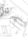
- Figure 1 an arrangement for carrying out Magnetic Resonance Imaging and X-ray imaging of a patient while the patient remains stationary on a patient support table.
- the arrangement provides a room 1 in which is mounted a patient support table 10 with doors 2 at one side of the room for entry into the room of the magnet 3 of an MR imaging system from a magnet bay 1 A.
- the room contains an X-ray imaging system 4 mounted on rails 5 and includes an X-ray transmitter 6 and receiver 7 mounted on a C-shaped support 8.
- the X-ray system is of a conventional construction commercially available from a manufacturer such as Siemens.
- the table 10 described and illustrated herein is used in an arrangement where the patient remains in position on the table while imaging is effected using MRI and X-ray.
- the magnet system 3 moves into a room within 1 minute, and the doors 2 open within seconds, so the limiting factor on effectiveness of usage of the magnet system is providing the patients into and out of the room, prepping the patients if required, and discussing the imaging with the patients. It is known that a reasonable amount of time per imaging event is 60 minutes, and therefore the movement of the MRI scanner into and out of a room is not the limiting time value. As well, the efficiency of a multi-room system becomes more difficult to schedule as the need for both diagnostic and interventional procedures occurs. The following configurations are now possible:
- a three room diagnostic configuration in which the central magnet holding bay 1 A houses the magnet and the diagnostic patients are organized in the three rooms including the room 1 and a further room not shown beyond the bay 1 A.
- the magnet may not move but may extend its diagnostic table, the patient lies on the diagnostic table, imaging is performed, no need to do intervention is found, the patient exits the diagnostic table and the magnet moves back into the holding bay, ready for use by one of the other rooms.
- the magnet then may draw in its table, rotates to the doors for that room, and the process for the other room begins. In this case, the magnet does not move in a translational direction, such as on rails, but simply rotates.
- a two room system is in the corner of the hospital.
- the magnet both rotates and translates.
- This approach allows existing diagnostic functionality and applications to be used in either room, or allows both rooms to serve as intra-operative rooms without any significant change to magnet controls and monitoring.
- This two room corner system cannot be done without a rotating magnet.
- the system can be suspended from the ceiling or mounted on a floor mounted bearing, with either system providing rotation of the magnet.
- the MRI system may also be suspended from the ceiling on rails, such that it can also be translated in space using the rail system.
- the rotational mechanism can either be located between the magnet and the rails, or above the rails.
- the below track and above track rotators have different properties for different configurations. The below track rotator allows for easiest upgrade of existing sites, whereas the above track rotator works like a roundhouse in a railway yard, in that the rail, MRI system and all associated systems are rotated.
- the system consists of the movable magnet integrated with an X-ray system such that the patient can be imaged by either modality on the same table. The patient does not move.
- the MR is a high-field horizontal or vertical type of magnet system that moves on overhead rails between the two or more rooms as described above.
- one or more of these rooms contains an X-ray system, either a single-plane or a biplane.
- the examination room functions as a conventional X-ray lab and can be used with conventional equipment. In particular, X-ray guided interventions may be performed.
- the arrangement may be used in a typical three room configuration with the Angiography Room (AR) on the left, a Diagnostic Room (DR) in the middle, and an Operating Room on the right.
- AR Angiography Room
- DR Diagnostic Room
- Operating Room on the right.
- the magnet moves on overhead rails between the rooms and can image in each.
- the X-ray equipment When MR imaging is required, the X-ray equipment is safely stowed, the doors open, and the magnet is brought into the room over the patient on the table.
- the RF shield encompasses the AR so all the equipment in the X-ray examination room is made RF-quiet. MR imaging can then be performed. Afterwards, the magnet is removed from the room, the doors closed, and the X-ray equipment is returned to its working position.
- the MR scanner is used to provide information complementary to that obtained using X-ray. It can be used, for example, to perform a baseline assessment prior to intervention as well as to perform a post-intervention assessment. Such an assessment may include perfusion and viability studies of, for example, the heart or of the brain.
- workflows for the system consider elective procedures and emergency cases, such as acute stroke or acute coronary syndromes.
- a preliminary, baseline MR scan can be obtained with the patient either in the diagnostic room or in the angiography room; this is basically a pre-procedure MR scan.
- the objective is to measure baseline parameters that are clinically relevant. For a cardiac procedure, this may include baseline cardiac function and myocardial viability.
- the patient is transferred to the angiography room if MR imaged in the diagnostic room, or simply remains on the table if already in the Angio room, where coronary or cerebral angiography and angioplasty, followed by stent placement are conducted, if required, in the customary fashion under X-ray fluoroscopy.
- the MR Scanner magnet enters the angiography room and acquires the appropriate MR images. After reviewing the MR data and possibly correlating with the X-Ray data, the interventionist can either discharge the patient or continue treatment.
- the patient In the emergency Case Workflow, the patient is admitted and undergoes preparation in the Emergency room (both groins shaved, screening for MR examination, metal check, etc.).
- the patient is brought to AR (in the case of an acute myocardial infarction diagnosed by ECG) and vascular access via the groin is established.
- MR Imaging could take place in the AR for baseline assessment in order to minimize movement of the acute patient.
- the scanner is brought into the AR for MR measurement of baseline cardiac function and perfusion imaging in a cardiac case. In the case of stroke, the MR images will reveal if interventional therapy is indicated.
- MR baseline imaging is completed and processed in a minimum time period.
- angiography and intervention are performed in the customary fashion, under X-Ray fluoroscopy, if so indicated.
- the MR Scanner is brought into the AR for subsequent MR images acquisition. After reviewing the MR images and possibly correlation with the X-ray data, the interventionist will discharge the patient or continue with treatment.
- the MR enters the X-ray examination room and moves over the head end of the table 10. Since the path of the MR passes right through the location of the C-arm stands, the latter must be moved before the magnet may enter.
- a floor-mounted C-arm stand may be moved on floor rails, floor turntable, or a boom mounted on the floor or wall.
- a ceiling-mounted C-arm stand may be moved using extended rails to park it at the foot end of the table, by mounting the stand rails on a platform suspended from the movable magnet rails, or by fixing the stand rails on a platform with a telescopic arm to move them laterally.
- Using a solution to move a floor-mounted stand together with a mover for a ceiling mounted stand provides a mechanism to move a biplane system.
- the mover can provide a mounting position of the single plane or biplane at some nonzero angle to the MR rails, e.g., 90 degrees.
- the Patient Handling System or support table is shown in Figures 2 to 7 as indicated generally at 10.
- the patient support table includes a base 11 of a conventional construction which allows the base to move a patient support portion 12 to required locations in height and in orientation. Suitable drive mechanisms and couplings are known in the art and thus are not required to be described herein.
- the patient support portion At the top of the base 12 is mounted the patient support portion in the form of a generally planar body 12 formed of a fiber reinforced plastics material so as to define a surface area sufficient for supporting the patient while lying on the patient support portion.
- the patient support 12 includes a rear edge 13 at or beyond the feet of the prone patient together with two side edges 14 and 15 spaced by a distance sufficient to receive and contain the legs, body and arms of the patient to be supported by the support portion.
- a head clamp 20 for mounting and 30 holding the head of the patient.
- a mattress 18 which is shaped to overlie the patient support portion 12.
- the structural support for the patient is provided by the support portion 12 which is formed of a fiber reinforced resin material where the fibers are laid in sheets and infused by the resin material to provide a flat structural member of sufficient strength to carry the weight of the typical patient.
- the fiber reinforcement selected for use in the structure of the portion 12 is a fiber which has sufficient strength to provide the necessary resistance to bending but a fiber which is non-electrically conductive.
- carbon fibers cannot be used since long carbon fibers generate or allow currents to flow within the structure of the portion and such currents will interfere with the necessary signals.
- the currents are generated by the high magnetic fields within the magnet and by the electro magnetic signals which are generated within the magnet for use in the magnetic resonance imaging.
- aramid fibers such as Kevlar (TM) can be used in replacement for the carbon fibers typically used in such structures.
- the mattress is formed of a stiff foam material encased by a skin to provide an exterior surface which is resistant to fluids and can be readily cleaned for sterilization to be used in clinical situations.
- the patient handling system thus contains the following key components: the patient table 11, the head holder 20, and MR imaging coils (not shown).
- the system including integration of the key components, is specially designed to permit imaging with both MRI and X-ray imaging modalities, while maintaining sufficient image quality and workflow.
- the patient table is designed to allow the patient to be scanned with both MR and X-ray imaging modalities.
- the patient table is comprised of two major components: the table pedestal and the tabletop.
- the tabletop is fully MR and X-ray compatible; the table pedestal does not adversely impact image quality during MR scanning (i.e. does not impact homogeneity of magnetic field), the pedestal also does not experience significant forces from the magnetic field.
- the tabletop is positioned so that the table pedestal (which is also not X-ray compatible) is at a distance that is sufficiently away from the imaging site.
- the tabletop integrates the head holder, arm boards and MR imaging coils.
- the head holder supports the patient's head during the procedure and must also be MR and X-ray compatible.
- the head holder integrates into the patient table in a manner that is very efficient to position and remove.
- the MR imaging head coils may also be integrated with the head holder and are easily positioned and removed at the imaging site.
- the MR imaging coils consist of head coils for imaging the head and upper spine.
- MR coils are not X-ray compatible and thus are positioned and removed from the imaging area when switching between imaging modalities without having to move or interfere with the patient.
- both X-ray and MR imaging modalities may be employed, at separate times during the procedure. Since MRI coils are not X-ray compatible, it is necessary to position and remove the coils quickly and easily when switching between MRI and X-ray imaging. For cases where it is necessary to keep the patient in a fixed position during the procedure, the imaging coils must also be positioned and removed without moving or shifting the patient in any way. For example, cranial procedures will employ the head holder to secure the head of the patient during the entire procedure. The MR imaging head coils will be easily positioned around the head holder without moving the head holder or the patient's head in any way.
- the patient table consists of a table top that is completely MR and X-ray compatible.
- the tabletop also enables the integration of various MR imaging coils, such as head coils and cardiac coils, with the special feature of positioning and removing the coils without moving or shifting the patient in any way.
- the tabletop also includes a means of easily positioning and removing the head holder; this includes a ridge or ledge around the head end of the tabletop, where the head holder may slide on with a dovetail interface.
- the imaging head coils also are integrated to the table in this fashion.
- the head holder and table adapter assembly include the head holder that secures the head during the procedure and also a table adapter that secures the head holder to the patient table and also provides a means of adjusting the position/orientation of the head holder.
- the entire assembly is completely MR and X-ray compatible.
- There are various means of securing the patient's head including a horseshoe head holder, a sling/suspender head holder, and a head cradle.
- the horseshoe head holder includes a rigid frame that is cushioned by gel, foam, or air inflated pillows; the sides and top of the patient's head may be supported by a strap or by side cushions.
- the frame may also be adjustable for accommodating a large range in head sizes.
- the sling/suspender head holder consists of soft material (e.g. fabric) that is shaped into a sling to support the back and sides of the head.
- the top of the head may be supported by a fabric strap; foam padding may insert between layers of material in the sides of the sling to cushion the head where the table adapter interfaces to the sling/suspender head holder.
- the head cradle is a scoop-shaped device that cradles the head and neck of the patient and includes foam or inflatable air pillows to cushion the back of the patient's head (for comfort) and also preventing the patient from moving the head from side to side.
- the pillow may be deflated to bring the head down slightly so that it is even closer to the portion of MR imaging head coil that is positioned directly underneath the head of the patient, which will increase MR image quality.
- the table adapter may interface to the head holder at various orientations, such as at the front of the head holder (closest to the patient's head), at the back of the head holder (furthest from patient table), along the sides of the head holder, or along the top of the head holder.
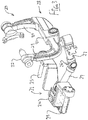
- the head holder shown in Figures 2 and 3 is of a conventional design and includes a mounting portion 22 which is connected to the end face of the table 20 by two mounting pins 23.
- the mounting portion includes a central boss 24 which connects to and supports a link 25 formed by two arms 27 and a plurality of swivel connecting joints 26 which allow the head holder clamp 28 to be moved to different positions to mount the head at a required position.
- the clamp 28 includes a three point mounting carried on two arms 29 and 30 which can be adjusted in spacing by a rack 31. One of the mounting points is carried on a screw 32 to allow the clamp to engage the head as required.
- the components for the head holder 20 are formed from the materials set out hereinafter. In many cases the parts a re machined from a supply portion of the material. In other cases the parts are fabricated.
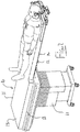
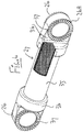
- FIG 4 is shown one example of the parts concerned which is one of the arms 27 with the swivel couplings 26 at opposite ends.
- Each swivel coupling includes a circular toothed face 26A which matches with a corresponding face of a next part so that the parts can be rotated about a central axis to provide angular adjustment.
- the arm 27 is manufactured from a main elongate bar 35 which carries at its ends two end coupling portions 36.
- Each end coupling portion carries two disk portions 37 which define the circular toothed face 26A.
- the end couplings 36 are formed of a material which is selected to provide a required strength and ability to be machined.
- a material to be used is Garolite which is manufactured by under the code G10-FR4 (FR4). This is a fire rated electrical-grade, dielectric fiberglass laminate epoxy resin system combined with a glass fabric substrate.
- the abbreviation "FR4" means: F (for flame) and R (for retardancy) and the 4 is a # 4 epoxy.
- FR4 grades offer excellent chemical resistance, flame ratings (UL94-VO) and electrical properties under dry and humid conditions.
- FR4 also features high flexural, impact, superior mechanical strength and bond strength at temperatures up to 130°C.
- glass fibers are epoxy resins reinforced by glass fibers.
- the use of glass fibers allows the finished product to be thinner than parts manufactured from other reinforcing fibers such as cotton which are conventionally believed to provide an improved reduction in Aluminum Equivalence Factor for use in the X-ray imaging but have been found to be unacceptable in MR imaging due to the creation of distortion and artifacts in the image.
- the circular disks 37 are formed from polyphenylene sulphide mixed with non-woven random fibreglass.
- Polyphenylene sulphide (PPS) is a high performance semi-crystalline polymer that offers an excellent combination of thermal, mechanical and chemical resistance properties. Applications requiring high temperature stability, toughness and chemical resistance at elevated temperatures, are good candidates for Polyphenylene sulphide.
- the bar 35 is formed from a composite of the polyurethane or polymethacrylimide foam enclosed by a layer of Aramid fibers.
- the polyurethane foam is a polymer consisting of a chain of organic units joined by (carbamate) links.
- Polyurethane polymers are formed by reacting a monomer containing at least two isocyanate functional groups with another monomer containing at least two alcohol groups in the presence of a catalyst.
- Polymethacrylimide foam is produced by thermal expansion of a copolymer sheet of methacrylic acid and methacrylonitrile. During the foaming process the copolymer sheet is converted to PMI - PolyMethacrylimide. Alcohol is used as a blowing agent. It has a very homogeneous cell structure and isotropic properties.
- the foam core is machined to a required shape and inserts may be applied to provide fasteners.
- the machined foam part is then covered with a layer of a woven fabric formed from aramid fibers.
- Aramid fibers are a class of heat-resistant and strong synthetic fiber. They are fibers in which the chain molecules are highly oriented along the fiber axis, so the strength of the chemical bond can be exploited.
- the woven sheet is supplied embedded in a non-cured polymer which can be cured in a press after the covering layer or layers are wrapped around the foam core. The curing action bonds the layer to the core so as to provide a structural composite part of the required strength. It will be appreciated that this part cannot be machined once formed and hence the end couplings 36 are formed from a machinable material and fastened to the structural bar by screw fasteners (not shown) and epoxy.
- Figure 5 shows a series of images taken in MR imaging which show a base line material together with the above materials in comparison with the base line material and the conventional Novotex.
- This test procedure is used to validate compatibility of materials with MRI systems.
- Tests are performed to verify that the material does not affect Signal to Noise Ratio (SNR) -
- SNR Signal to Noise Ratio
- the RF field (gradient filed) distortions.
- the object under the test should not cause to any inhomogeneity of the RF field.
- This procedure applies to estimate the X-ray attenuation of the test material, which is the only way to qualify the material in the numeric way, to be compatible as a part of international regulation bodies (FDA, IEC and etc) and to ensure that no harmful affect will be induced to the patient due to normal X-ray exposure.
- Aluminum Equivalence is the thickness of type 1100 Aluminum that affords the same x-ray attenuation as the material to be tested. The attenuation must be measured with x-rays of a specified Beam Quality.
- Beam Quality is a measure of the hardness (relative penetrating power) of an x-ray beam. It is specified by two numbers: (1) the x-ray tube voltage (kVp); and (2) the thickness of type 1100 Aluminum that reduces the exposure rate of the beam by one-half, known as the half-value layer (HVL).
- AI equivalence is measured with a beam having a half-value layer of 3.7 mm at 100 kVp.
- the above part 27 defines a structural support component for use in imaging of a part of a patient using Magnetic Resonance and X-ray imaging where the structural support component is formed of one or more materials each of which has an Aluminum equivalence factor of less than 10mm and preferably of the order of 5 to 5mm.
- the structural support component is arranged such that the presence of the structural support component in an imaging zone of a magnetic resonance imaging system when generating the image does not generate any visually determinable distortion in the image.
- the finished part should go thru complete X-ray test to determine the AI equivalence number and the level of visual interference of the MR image, if any.
- the component is formed of two or more different materials where the materials have different physical characteristics.
- one of the materials used for the disk 37 is harder is and is used to form wear parts where two separate parts are butting.
- one of the materials is more rigid is and is used to form elongate bars 35.
- the component as shown at 35 is formed of three different materials where the materials have different physical characteristics, with the first material selected to form the elongate bar 36, the second material selected to form machined end portions 36 of the bar and the third material selected to form wear parts 37 attached to the end portions.
Landscapes
- Health & Medical Sciences (AREA)
- Physics & Mathematics (AREA)
- Life Sciences & Earth Sciences (AREA)
- Engineering & Computer Science (AREA)
- Nuclear Medicine, Radiotherapy & Molecular Imaging (AREA)
- Medical Informatics (AREA)
- General Health & Medical Sciences (AREA)
- Pathology (AREA)
- Surgery (AREA)
- Animal Behavior & Ethology (AREA)
- General Physics & Mathematics (AREA)
- Molecular Biology (AREA)
- Biomedical Technology (AREA)
- Theoretical Computer Science (AREA)
- Public Health (AREA)
- Veterinary Medicine (AREA)
- Radiology & Medical Imaging (AREA)
- Condensed Matter Physics & Semiconductors (AREA)
- Heart & Thoracic Surgery (AREA)
- High Energy & Nuclear Physics (AREA)
- Biophysics (AREA)
- Optics & Photonics (AREA)
- Neurosurgery (AREA)
- Oral & Maxillofacial Surgery (AREA)
- Pulmonology (AREA)
- Magnetic Resonance Imaging Apparatus (AREA)
- Apparatus For Radiation Diagnosis (AREA)
Applications Claiming Priority (2)
| Application Number | Priority Date | Filing Date | Title |
|---|---|---|---|
| US12/413,953 US8245335B2 (en) | 2009-03-30 | 2009-03-30 | Support component for use in imaging by magnetic resonance and x-ray |
| PCT/CA2010/000422 WO2010111772A1 (en) | 2009-03-30 | 2010-03-29 | Support component for use in imaging by magnetic resonance and x-ray |
Publications (3)
| Publication Number | Publication Date |
|---|---|
| EP2413794A1 EP2413794A1 (en) | 2012-02-08 |
| EP2413794A4 EP2413794A4 (en) | 2018-01-17 |
| EP2413794B1 true EP2413794B1 (en) | 2021-03-24 |
Family
ID=42785094
Family Applications (1)
| Application Number | Title | Priority Date | Filing Date |
|---|---|---|---|
| EP10757962.5A Active EP2413794B1 (en) | 2009-03-30 | 2010-03-29 | Support component for use in imaging by magnetic resonance and x-ray |
Country Status (4)
| Country | Link |
|---|---|
| US (1) | US8245335B2 (enExample) |
| EP (1) | EP2413794B1 (enExample) |
| JP (1) | JP5531371B2 (enExample) |
| WO (1) | WO2010111772A1 (enExample) |
Families Citing this family (19)
| Publication number | Priority date | Publication date | Assignee | Title |
|---|---|---|---|---|
| US20100059064A1 (en) * | 2008-05-09 | 2010-03-11 | Schuele Edgar Franz | Method and Apparatus for Using a Surgical Fixture in an Intra-Operative Computed Tomography Scanner |
| US8245335B2 (en) * | 2009-03-30 | 2012-08-21 | Imns Inc. | Support component for use in imaging by magnetic resonance and x-ray |
| EA201101683A1 (ru) * | 2009-06-08 | 2012-06-29 | Онколог Медикал Ка Аб | Пластина стола для лучевой терапии |
| US8901928B2 (en) * | 2010-11-09 | 2014-12-02 | Imris Inc. | MRI safety system |
| ES2523825T3 (es) | 2011-06-15 | 2014-12-01 | Imris Inc. | Integración de IRM en tratamiento con radioterapia |
| US9204818B2 (en) | 2012-01-16 | 2015-12-08 | Imris Inc | Drive system for a head clamp for use in imaging by Magnetic Resonance and X-ray |
| DE102012203119A1 (de) * | 2012-02-29 | 2013-08-29 | Siemens Aktiengesellschaft | Patientenlagerungsvorrichtung sowie eine medizinische Bildgebungsvorrichtung mit der Patientenlagerungsvorrichtung |
| DE102012212500B4 (de) * | 2012-07-17 | 2017-11-16 | Siemens Healthcare Gmbh | Patientenlagerungsvorrichtung |
| DE102012214449B4 (de) * | 2012-08-14 | 2014-07-10 | Siemens Aktiengesellschaft | Patientenlagerungsvorrichtung sowie eine die Patientenlagerungsvorrichtung umfassende medizinische Bildgebungsvorrichtung |
| GB201215877D0 (en) * | 2012-09-05 | 2012-10-24 | Renishaw Plc | Medical imaging accessory |
| JP6505360B2 (ja) * | 2012-11-22 | 2019-04-24 | キヤノンメディカルシステムズ株式会社 | 磁気共鳴撮像装置及びその制御方法 |
| EP2774537A1 (en) | 2013-03-08 | 2014-09-10 | Imris Inc. | Patient alignment in MRI guided radiation therapy |
| US20140275962A1 (en) * | 2013-03-12 | 2014-09-18 | General Electric Company | Methods and systems using magnetic resonance and ultrasound for tracking anatomical targets for radiation therapy guidance |
| DE102016004231A1 (de) * | 2016-04-08 | 2017-10-12 | Cival Medical Gmbh | Chirurgische Schädelklemme |
| US10694976B2 (en) * | 2017-05-04 | 2020-06-30 | Elekta Ltd. | Squeeze protection |
| EP3552544A1 (en) | 2018-04-12 | 2019-10-16 | Medical Intelligence Medizintechnik GmbH | Mri compatible fixation frame |
| CN111588378A (zh) * | 2019-02-20 | 2020-08-28 | 郭凌飞 | 一种头部固定的磁共振检查装置 |
| EP3938191A1 (en) * | 2019-03-15 | 2022-01-19 | Pro Med Instruments GmbH | Method of manufacturing head fixation device components |
| CN113740361B (zh) * | 2020-05-29 | 2023-05-23 | 清华大学 | 检测通道、通道组件和ct检测装置 |
Family Cites Families (44)
| Publication number | Priority date | Publication date | Assignee | Title |
|---|---|---|---|---|
| US4566445A (en) * | 1983-07-29 | 1986-01-28 | Jelsma Richard K | Stretcher for persons with spinal injuries |
| US4595899A (en) | 1984-07-06 | 1986-06-17 | The Board Of Trustees Of The Leland Stanford Junior University | Magnetic structure for NMR applications and the like |
| US4698837A (en) * | 1985-03-11 | 1987-10-06 | Amatech Corporation | Armboard mounting assembly |
| US4926457A (en) * | 1988-01-29 | 1990-05-15 | Hill-Rom Company, Inc. | Radiolucent hospital bed surface |
| DE3833594A1 (de) * | 1988-10-03 | 1990-04-05 | Philips Patentverwaltung | Patientenliege fuer diagnostische geraete |
| US5099846A (en) | 1988-12-23 | 1992-03-31 | Hardy Tyrone L | Method and apparatus for video presentation from a variety of scanner imaging sources |
| DE3931854A1 (de) | 1989-09-23 | 1991-04-04 | Berlin Laser Medizin Zentrum | Nmr-tomographisch gesteuerte stereotaktische laser-koagulation |
| US5044462A (en) | 1990-07-31 | 1991-09-03 | Halliburton Logging Services, Inc. | Focused planar transducer |
| US5042462A (en) * | 1990-10-30 | 1991-08-27 | Bremer Paul W | Cervical traction tongs |
| JPH04183446A (ja) | 1990-11-19 | 1992-06-30 | Res Dev Corp Of Japan | 画像合成による手術支援システム |
| US5291890A (en) | 1991-08-29 | 1994-03-08 | General Electric Company | Magnetic resonance surgery using heat waves produced with focussed ultrasound |
| JPH05344964A (ja) | 1992-06-15 | 1993-12-27 | Toshiba Corp | Ct装置 |
| EP0716577B1 (en) | 1994-06-30 | 2003-05-02 | Koninklijke Philips Electronics N.V. | Magnetic resonance device comprising an x-ray device |
| EP0744912A1 (en) | 1994-11-24 | 1996-12-04 | Koninklijke Philips Electronics N.V. | Magnetic resonance device comprising an x-ray device |
| US5865780A (en) | 1995-10-13 | 1999-02-02 | Sdgi Holdings, Inc. | Transportable cervical immobilization device |
| US5735278A (en) | 1996-03-15 | 1998-04-07 | National Research Council Of Canada | Surgical procedure with magnetic resonance imaging |
| US5771513A (en) * | 1996-06-03 | 1998-06-30 | Beta Medical Products, Inc. | X-ray compatible, partially flexible patient support |
| US5950627A (en) * | 1996-12-24 | 1999-09-14 | Laerdal Medical Corporation | Spine board |
| JP3862798B2 (ja) | 1997-01-13 | 2006-12-27 | 株式会社日立メディコ | 医療用画像診断装置 |
| US5996149A (en) * | 1997-07-17 | 1999-12-07 | Hill-Rom, Inc. | Trauma stretcher apparatus |
| DE19901482B4 (de) | 1999-01-15 | 2004-01-15 | Siemens Ag | Angio-MR-System |
| US6975895B1 (en) | 2000-03-30 | 2005-12-13 | The Board Of Trustees Of The Leland Stanford Junior University | Modified X-ray tube for use in the presence of magnetic fields |
| DE10038176C1 (de) | 2000-08-04 | 2001-08-16 | Siemens Ag | Medizinische Untersuchungsanlage mit einem MR-System und einem Röntgensystem |
| US6754519B1 (en) | 2000-11-24 | 2004-06-22 | Elgems Ltd. | Multimodality imaging system |
| US6961606B2 (en) | 2001-10-19 | 2005-11-01 | Koninklijke Philips Electronics N.V. | Multimodality medical imaging system and method with separable detector devices |
| US6782571B1 (en) * | 2001-11-30 | 2004-08-31 | Ge Medical Systems | Patient transport system for multiple imaging systems |
| US6640364B1 (en) * | 2001-11-30 | 2003-11-04 | Ge Medical Systems Global Technololgy Company, Llc | Pedestal for use with patient transport system for multiple imaging systems |
| JP4183446B2 (ja) | 2002-07-01 | 2008-11-19 | 不二サッシ株式会社 | 太陽光発電装置 |
| US6812700B2 (en) | 2002-08-05 | 2004-11-02 | The Board Of Trustees Of The Leland Stanford Junior University | Correction of local field inhomogeneity in magnetic resonance imaging apparatus |
| WO2004071320A1 (en) | 2003-02-10 | 2004-08-26 | Integra Ohio, Inc. | Radiolucent skull clamp with removable pin load applicator |
| WO2004084751A2 (en) | 2003-03-21 | 2004-10-07 | Schaerer Mayfield Usa, Inc. | Swivel adapter and base unit handle |
| US7484253B1 (en) * | 2003-05-27 | 2009-02-03 | Qfix Systems, Llc | Patient support element for radiation therapy that reduces skin radiation burn |
| CA2891712A1 (en) * | 2003-08-12 | 2005-03-03 | Loma Linda University Medical Center | Patient positioning system for radiation therapy system |
| EP1850756B1 (en) * | 2005-02-08 | 2015-01-21 | QFix Systems LLC | A rigid patient support element for low patient skin damage when used in a radiation therapy environment |
| US20060239524A1 (en) | 2005-03-31 | 2006-10-26 | Vladimir Desh | Dedicated display for processing and analyzing multi-modality cardiac data |
| WO2007014233A1 (en) | 2005-07-26 | 2007-02-01 | The Procter & Gamble Company | Flexible absorbent article with improved body fit |
| US10315046B2 (en) | 2005-12-02 | 2019-06-11 | The Johns Hopkins University | Multi-imager compatible robot for image-guided interventions and fully automated brachytherapy seed |
| US20070238950A1 (en) * | 2006-03-24 | 2007-10-11 | Vija A H | Separate and combined multi-modality diagnostic imaging system |
| CA2651047C (en) | 2006-06-20 | 2014-04-29 | Imris Inc. | Movable integrated scanner for surgical imaging applications |
| US7552492B2 (en) | 2006-09-22 | 2009-06-30 | Integra Lifesciences Corporation | Head support base unit with multi-directional capability |
| US7742562B2 (en) * | 2007-06-27 | 2010-06-22 | Accuray Incorporated | Lower-torso assembly of a treatment couch useable in an X-ray environment |
| US8623029B2 (en) | 2008-03-12 | 2014-01-07 | Neurologica Corp. | Composite skull pins with reduced X-ray signature |
| DE102009023806B4 (de) | 2008-07-09 | 2011-04-28 | Siemens Aktiengesellschaft | Kombinierte PET-MR-Einrichtung, Bauteil und Lokalspule |
| US8245335B2 (en) * | 2009-03-30 | 2012-08-21 | Imns Inc. | Support component for use in imaging by magnetic resonance and x-ray |
-
2009
- 2009-03-30 US US12/413,953 patent/US8245335B2/en active Active
-
2010
- 2010-03-29 EP EP10757962.5A patent/EP2413794B1/en active Active
- 2010-03-29 WO PCT/CA2010/000422 patent/WO2010111772A1/en not_active Ceased
- 2010-03-29 JP JP2012502403A patent/JP5531371B2/ja active Active
Non-Patent Citations (1)
| Title |
|---|
| None * |
Also Published As
| Publication number | Publication date |
|---|---|
| US20100249575A1 (en) | 2010-09-30 |
| JP2012521814A (ja) | 2012-09-20 |
| JP5531371B2 (ja) | 2014-06-25 |
| EP2413794A1 (en) | 2012-02-08 |
| WO2010111772A1 (en) | 2010-10-07 |
| EP2413794A4 (en) | 2018-01-17 |
| US8245335B2 (en) | 2012-08-21 |
Similar Documents
| Publication | Publication Date | Title |
|---|---|---|
| EP2413794B1 (en) | Support component for use in imaging by magnetic resonance and x-ray | |
| US9204818B2 (en) | Drive system for a head clamp for use in imaging by Magnetic Resonance and X-ray | |
| US8369929B2 (en) | Patient support table for use in magnetic resonace imaging | |
| US8190235B2 (en) | System for magnetic resonance and X-Ray imaging | |
| Peters et al. | Integrated stereotaxic imaging with CT, MR imaging, and digital subtraction angiography. | |
| EP1211980B1 (en) | Surgical scanner system | |
| US7395563B2 (en) | Support system for use when performing medical imaging of a patient | |
| US6928672B2 (en) | Patient positioning and transport system | |
| US11206995B2 (en) | Safe infant MR imaging system | |
| US20070238950A1 (en) | Separate and combined multi-modality diagnostic imaging system | |
| US8513946B2 (en) | Movable table for magnetic resonance imaging | |
| US20130324834A1 (en) | Head Clamp for Use in Imaging by Magnetic Resonance and X-Ray | |
| EP2155136B1 (en) | Patient transporter for imaging and intervention | |
| CA2661674C (en) | Support component for use in imaging by magnetic resonance and x-ray | |
| CA2646939C (en) | Patient support table for use in magnetic resonance imaging | |
| US20240245318A1 (en) | Magnetic resonance systems having ultra-wide bores and patient support assemblies with precise positioning | |
| Wirtz et al. | Modified headholder and operating table for intra-operative MRI in neurosurgery | |
| Parizel et al. | Stereotaxic target calculation: Theory and practice |
Legal Events
| Date | Code | Title | Description |
|---|---|---|---|
| PUAI | Public reference made under article 153(3) epc to a published international application that has entered the european phase |
Free format text: ORIGINAL CODE: 0009012 |
|
| 17P | Request for examination filed |
Effective date: 20111031 |
|
| AK | Designated contracting states |
Kind code of ref document: A1 Designated state(s): AT BE BG CH CY CZ DE DK EE ES FI FR GB GR HR HU IE IS IT LI LT LU LV MC MK MT NL NO PL PT RO SE SI SK SM TR |
|
| DAX | Request for extension of the european patent (deleted) | ||
| RA4 | Supplementary search report drawn up and despatched (corrected) |
Effective date: 20171215 |
|
| RIC1 | Information provided on ipc code assigned before grant |
Ipc: G01R 33/30 20060101ALI20171211BHEP Ipc: A61B 5/055 20060101AFI20171211BHEP Ipc: G01R 33/48 20060101ALI20171211BHEP Ipc: A61B 90/14 20160101ALI20171211BHEP Ipc: A61G 13/10 20060101ALI20171211BHEP Ipc: A61B 6/00 20060101ALI20171211BHEP |
|
| RAP1 | Party data changed (applicant data changed or rights of an application transferred) |
Owner name: PETROPOULOS, LABROS L. Owner name: IMRIS INC. |
|
| REG | Reference to a national code |
Ref country code: DE Ref legal event code: R079 Ref document number: 602010066650 Country of ref document: DE Free format text: PREVIOUS MAIN CLASS: A61B0005055000 Ipc: G01R0033480000 |
|
| GRAP | Despatch of communication of intention to grant a patent |
Free format text: ORIGINAL CODE: EPIDOSNIGR1 |
|
| STAA | Information on the status of an ep patent application or granted ep patent |
Free format text: STATUS: GRANT OF PATENT IS INTENDED |
|
| RIC1 | Information provided on ipc code assigned before grant |
Ipc: A61B 90/14 20160101ALI20200922BHEP Ipc: G01R 33/28 20060101ALI20200922BHEP Ipc: A61B 5/055 20060101ALI20200922BHEP Ipc: G01R 33/48 20060101AFI20200922BHEP Ipc: A61B 6/00 20060101ALI20200922BHEP Ipc: A61G 13/10 20060101ALI20200922BHEP Ipc: A61B 6/04 20060101ALI20200922BHEP |
|
| INTG | Intention to grant announced |
Effective date: 20201016 |
|
| GRAS | Grant fee paid |
Free format text: ORIGINAL CODE: EPIDOSNIGR3 |
|
| GRAA | (expected) grant |
Free format text: ORIGINAL CODE: 0009210 |
|
| STAA | Information on the status of an ep patent application or granted ep patent |
Free format text: STATUS: THE PATENT HAS BEEN GRANTED |
|
| AK | Designated contracting states |
Kind code of ref document: B1 Designated state(s): AT BE BG CH CY CZ DE DK EE ES FI FR GB GR HR HU IE IS IT LI LT LU LV MC MK MT NL NO PL PT RO SE SI SK SM TR |
|
| REG | Reference to a national code |
Ref country code: GB Ref legal event code: FG4D |
|
| REG | Reference to a national code |
Ref country code: CH Ref legal event code: EP |
|
| REG | Reference to a national code |
Ref country code: DE Ref legal event code: R096 Ref document number: 602010066650 Country of ref document: DE |
|
| REG | Reference to a national code |
Ref country code: IE Ref legal event code: FG4D |
|
| REG | Reference to a national code |
Ref country code: AT Ref legal event code: REF Ref document number: 1375043 Country of ref document: AT Kind code of ref document: T Effective date: 20210415 |
|
| REG | Reference to a national code |
Ref country code: SE Ref legal event code: TRGR |
|
| REG | Reference to a national code |
Ref country code: NL Ref legal event code: FP |
|
| REG | Reference to a national code |
Ref country code: LT Ref legal event code: MG9D |
|
| PG25 | Lapsed in a contracting state [announced via postgrant information from national office to epo] |
Ref country code: NO Free format text: LAPSE BECAUSE OF FAILURE TO SUBMIT A TRANSLATION OF THE DESCRIPTION OR TO PAY THE FEE WITHIN THE PRESCRIBED TIME-LIMIT Effective date: 20210624 Ref country code: BG Free format text: LAPSE BECAUSE OF FAILURE TO SUBMIT A TRANSLATION OF THE DESCRIPTION OR TO PAY THE FEE WITHIN THE PRESCRIBED TIME-LIMIT Effective date: 20210624 Ref country code: GR Free format text: LAPSE BECAUSE OF FAILURE TO SUBMIT A TRANSLATION OF THE DESCRIPTION OR TO PAY THE FEE WITHIN THE PRESCRIBED TIME-LIMIT Effective date: 20210625 Ref country code: HR Free format text: LAPSE BECAUSE OF FAILURE TO SUBMIT A TRANSLATION OF THE DESCRIPTION OR TO PAY THE FEE WITHIN THE PRESCRIBED TIME-LIMIT Effective date: 20210324 Ref country code: FI Free format text: LAPSE BECAUSE OF FAILURE TO SUBMIT A TRANSLATION OF THE DESCRIPTION OR TO PAY THE FEE WITHIN THE PRESCRIBED TIME-LIMIT Effective date: 20210324 |
|
| PG25 | Lapsed in a contracting state [announced via postgrant information from national office to epo] |
Ref country code: LV Free format text: LAPSE BECAUSE OF FAILURE TO SUBMIT A TRANSLATION OF THE DESCRIPTION OR TO PAY THE FEE WITHIN THE PRESCRIBED TIME-LIMIT Effective date: 20210324 |
|
| REG | Reference to a national code |
Ref country code: AT Ref legal event code: MK05 Ref document number: 1375043 Country of ref document: AT Kind code of ref document: T Effective date: 20210324 |
|
| PG25 | Lapsed in a contracting state [announced via postgrant information from national office to epo] |
Ref country code: AT Free format text: LAPSE BECAUSE OF FAILURE TO SUBMIT A TRANSLATION OF THE DESCRIPTION OR TO PAY THE FEE WITHIN THE PRESCRIBED TIME-LIMIT Effective date: 20210324 Ref country code: SM Free format text: LAPSE BECAUSE OF FAILURE TO SUBMIT A TRANSLATION OF THE DESCRIPTION OR TO PAY THE FEE WITHIN THE PRESCRIBED TIME-LIMIT Effective date: 20210324 Ref country code: EE Free format text: LAPSE BECAUSE OF FAILURE TO SUBMIT A TRANSLATION OF THE DESCRIPTION OR TO PAY THE FEE WITHIN THE PRESCRIBED TIME-LIMIT Effective date: 20210324 Ref country code: CZ Free format text: LAPSE BECAUSE OF FAILURE TO SUBMIT A TRANSLATION OF THE DESCRIPTION OR TO PAY THE FEE WITHIN THE PRESCRIBED TIME-LIMIT Effective date: 20210324 Ref country code: LT Free format text: LAPSE BECAUSE OF FAILURE TO SUBMIT A TRANSLATION OF THE DESCRIPTION OR TO PAY THE FEE WITHIN THE PRESCRIBED TIME-LIMIT Effective date: 20210324 |
|
| PG25 | Lapsed in a contracting state [announced via postgrant information from national office to epo] |
Ref country code: IS Free format text: LAPSE BECAUSE OF FAILURE TO SUBMIT A TRANSLATION OF THE DESCRIPTION OR TO PAY THE FEE WITHIN THE PRESCRIBED TIME-LIMIT Effective date: 20210724 Ref country code: RO Free format text: LAPSE BECAUSE OF FAILURE TO SUBMIT A TRANSLATION OF THE DESCRIPTION OR TO PAY THE FEE WITHIN THE PRESCRIBED TIME-LIMIT Effective date: 20210324 Ref country code: ES Free format text: LAPSE BECAUSE OF FAILURE TO SUBMIT A TRANSLATION OF THE DESCRIPTION OR TO PAY THE FEE WITHIN THE PRESCRIBED TIME-LIMIT Effective date: 20210324 Ref country code: PT Free format text: LAPSE BECAUSE OF FAILURE TO SUBMIT A TRANSLATION OF THE DESCRIPTION OR TO PAY THE FEE WITHIN THE PRESCRIBED TIME-LIMIT Effective date: 20210726 Ref country code: PL Free format text: LAPSE BECAUSE OF FAILURE TO SUBMIT A TRANSLATION OF THE DESCRIPTION OR TO PAY THE FEE WITHIN THE PRESCRIBED TIME-LIMIT Effective date: 20210324 Ref country code: SK Free format text: LAPSE BECAUSE OF FAILURE TO SUBMIT A TRANSLATION OF THE DESCRIPTION OR TO PAY THE FEE WITHIN THE PRESCRIBED TIME-LIMIT Effective date: 20210324 |
|
| REG | Reference to a national code |
Ref country code: BE Ref legal event code: MM Effective date: 20210331 |
|
| REG | Reference to a national code |
Ref country code: DE Ref legal event code: R097 Ref document number: 602010066650 Country of ref document: DE |
|
| PG25 | Lapsed in a contracting state [announced via postgrant information from national office to epo] |
Ref country code: IE Free format text: LAPSE BECAUSE OF NON-PAYMENT OF DUE FEES Effective date: 20210329 Ref country code: DK Free format text: LAPSE BECAUSE OF FAILURE TO SUBMIT A TRANSLATION OF THE DESCRIPTION OR TO PAY THE FEE WITHIN THE PRESCRIBED TIME-LIMIT Effective date: 20210324 Ref country code: LU Free format text: LAPSE BECAUSE OF NON-PAYMENT OF DUE FEES Effective date: 20210329 Ref country code: MC Free format text: LAPSE BECAUSE OF FAILURE TO SUBMIT A TRANSLATION OF THE DESCRIPTION OR TO PAY THE FEE WITHIN THE PRESCRIBED TIME-LIMIT Effective date: 20210324 |
|
| PLBE | No opposition filed within time limit |
Free format text: ORIGINAL CODE: 0009261 |
|
| STAA | Information on the status of an ep patent application or granted ep patent |
Free format text: STATUS: NO OPPOSITION FILED WITHIN TIME LIMIT |
|
| PG25 | Lapsed in a contracting state [announced via postgrant information from national office to epo] |
Ref country code: SI Free format text: LAPSE BECAUSE OF FAILURE TO SUBMIT A TRANSLATION OF THE DESCRIPTION OR TO PAY THE FEE WITHIN THE PRESCRIBED TIME-LIMIT Effective date: 20210324 |
|
| 26N | No opposition filed |
Effective date: 20220104 |
|
| PG25 | Lapsed in a contracting state [announced via postgrant information from national office to epo] |
Ref country code: IS Free format text: LAPSE BECAUSE OF FAILURE TO SUBMIT A TRANSLATION OF THE DESCRIPTION OR TO PAY THE FEE WITHIN THE PRESCRIBED TIME-LIMIT Effective date: 20210724 |
|
| PG25 | Lapsed in a contracting state [announced via postgrant information from national office to epo] |
Ref country code: BE Free format text: LAPSE BECAUSE OF NON-PAYMENT OF DUE FEES Effective date: 20210331 |
|
| PG25 | Lapsed in a contracting state [announced via postgrant information from national office to epo] |
Ref country code: IT Free format text: LAPSE BECAUSE OF FAILURE TO SUBMIT A TRANSLATION OF THE DESCRIPTION OR TO PAY THE FEE WITHIN THE PRESCRIBED TIME-LIMIT Effective date: 20210324 |
|
| PG25 | Lapsed in a contracting state [announced via postgrant information from national office to epo] |
Ref country code: HU Free format text: LAPSE BECAUSE OF FAILURE TO SUBMIT A TRANSLATION OF THE DESCRIPTION OR TO PAY THE FEE WITHIN THE PRESCRIBED TIME-LIMIT; INVALID AB INITIO Effective date: 20100329 Ref country code: CY Free format text: LAPSE BECAUSE OF FAILURE TO SUBMIT A TRANSLATION OF THE DESCRIPTION OR TO PAY THE FEE WITHIN THE PRESCRIBED TIME-LIMIT Effective date: 20210324 |
|
| PG25 | Lapsed in a contracting state [announced via postgrant information from national office to epo] |
Ref country code: MK Free format text: LAPSE BECAUSE OF FAILURE TO SUBMIT A TRANSLATION OF THE DESCRIPTION OR TO PAY THE FEE WITHIN THE PRESCRIBED TIME-LIMIT Effective date: 20210324 |
|
| PG25 | Lapsed in a contracting state [announced via postgrant information from national office to epo] |
Ref country code: MT Free format text: LAPSE BECAUSE OF FAILURE TO SUBMIT A TRANSLATION OF THE DESCRIPTION OR TO PAY THE FEE WITHIN THE PRESCRIBED TIME-LIMIT Effective date: 20210324 |
|
| PGFP | Annual fee paid to national office [announced via postgrant information from national office to epo] |
Ref country code: SE Payment date: 20250331 Year of fee payment: 16 |
|
| PGFP | Annual fee paid to national office [announced via postgrant information from national office to epo] |
Ref country code: NL Payment date: 20250331 Year of fee payment: 16 |
|
| PGFP | Annual fee paid to national office [announced via postgrant information from national office to epo] |
Ref country code: FR Payment date: 20250331 Year of fee payment: 16 |
|
| PGFP | Annual fee paid to national office [announced via postgrant information from national office to epo] |
Ref country code: DE Payment date: 20250422 Year of fee payment: 16 |
|
| PGFP | Annual fee paid to national office [announced via postgrant information from national office to epo] |
Ref country code: GB Payment date: 20250423 Year of fee payment: 16 |
|
| PGFP | Annual fee paid to national office [announced via postgrant information from national office to epo] |
Ref country code: CH Payment date: 20250403 Year of fee payment: 16 |
|
| PG25 | Lapsed in a contracting state [announced via postgrant information from national office to epo] |
Ref country code: TR Free format text: LAPSE BECAUSE OF FAILURE TO SUBMIT A TRANSLATION OF THE DESCRIPTION OR TO PAY THE FEE WITHIN THE PRESCRIBED TIME-LIMIT Effective date: 20210324 |