EP2413621B1 - Mobile communication between a mobile terminal device and at least one information terminal device over a packet data network connection (pdn) based on an access point name (apn), an evolved packet system (eps) bearer id and an address block which are received from an external gateway device - Google Patents
Mobile communication between a mobile terminal device and at least one information terminal device over a packet data network connection (pdn) based on an access point name (apn), an evolved packet system (eps) bearer id and an address block which are received from an external gateway device Download PDFInfo
- Publication number
- EP2413621B1 EP2413621B1 EP10755704.3A EP10755704A EP2413621B1 EP 2413621 B1 EP2413621 B1 EP 2413621B1 EP 10755704 A EP10755704 A EP 10755704A EP 2413621 B1 EP2413621 B1 EP 2413621B1
- Authority
- EP
- European Patent Office
- Prior art keywords
- terminal device
- pdn
- mobile terminal
- pdn connection
- address
- Prior art date
- Legal status (The legal status is an assumption and is not a legal conclusion. Google has not performed a legal analysis and makes no representation as to the accuracy of the status listed.)
- Active
Links
Images


Classifications
-
- H—ELECTRICITY
- H04—ELECTRIC COMMUNICATION TECHNIQUE
- H04W—WIRELESS COMMUNICATION NETWORKS
- H04W76/00—Connection management
- H04W76/10—Connection setup
- H04W76/12—Setup of transport tunnels
-
- H—ELECTRICITY
- H04—ELECTRIC COMMUNICATION TECHNIQUE
- H04L—TRANSMISSION OF DIGITAL INFORMATION, e.g. TELEGRAPHIC COMMUNICATION
- H04L9/00—Cryptographic mechanisms or cryptographic arrangements for secret or secure communications; Network security protocols
- H04L9/40—Network security protocols
-
- H—ELECTRICITY
- H04—ELECTRIC COMMUNICATION TECHNIQUE
- H04W—WIRELESS COMMUNICATION NETWORKS
- H04W40/00—Communication routing or communication path finding
- H04W40/24—Connectivity information management, e.g. connectivity discovery or connectivity update
-
- H—ELECTRICITY
- H04—ELECTRIC COMMUNICATION TECHNIQUE
- H04W—WIRELESS COMMUNICATION NETWORKS
- H04W8/00—Network data management
- H04W8/26—Network addressing or numbering for mobility support
-
- H—ELECTRICITY
- H04—ELECTRIC COMMUNICATION TECHNIQUE
- H04W—WIRELESS COMMUNICATION NETWORKS
- H04W92/00—Interfaces specially adapted for wireless communication networks
- H04W92/02—Inter-networking arrangements
-
- H—ELECTRICITY
- H04—ELECTRIC COMMUNICATION TECHNIQUE
- H04L—TRANSMISSION OF DIGITAL INFORMATION, e.g. TELEGRAPHIC COMMUNICATION
- H04L2101/00—Indexing scheme associated with group H04L61/00
- H04L2101/60—Types of network addresses
- H04L2101/618—Details of network addresses
- H04L2101/659—Internet protocol version 6 [IPv6] addresses
-
- H—ELECTRICITY
- H04—ELECTRIC COMMUNICATION TECHNIQUE
- H04W—WIRELESS COMMUNICATION NETWORKS
- H04W84/00—Network topologies
- H04W84/18—Self-organising networks, e.g. ad-hoc networks or sensor networks
Definitions
- the present invention relates to a mobile communication system, and particularly to a mobile communication system connected to an external packet data network.
- an MT Mobile Terminal
- a TE Terminal Equipment
- UE User Equipment
- Patent Document 1 discloses a method whereby, rather than a TE-MT interface, an Ethernet (registered trademark) and DHCP (Dynamic Host Configuration Protocol) are used to allocate an IP (Internet Protocol) address to the TE and make connection to the PDN. Additionally, it is assumed that it will be possible to use this TE-MT interface in the EPS (Evolved Packet System), which is standardized as the next-generation mobile communication system by the 3GPP (3rd Generation Partnership Project).
- EPS Evolved Packet System
- the protocol for connecting a UE to the PDN in an EPS is set forth in the Non-Patent Document 2 (TS 23.401).
- the UE after first being attached to the wireless access network, establishes a logical path connection to the PDN, which is known as a PDN connection.
- the PDN is uniquely identified by the APN (Access Point Name), and is connected to the core network via a PDN-GW, which is an external gateway equipment.
- the PDN connection is established individually for each PDN-GW that is connected to the UE. Even via one and the same PDN-GW, when connections are made to different PDNs, independent PDN connections are required.
- One PDN connection combines a plurality of logical paths that is known as an EPS bearer when transferring a user IP packet, and it is further possible to assign a QoS (Quality of Service) class and a charging rule or the like to each EPS bearer. Therefore, using the UE packet transmission destination and transport protocol, it is possible to apply different QoS classes and charging rules to each IP packet, using a port number.
- QoS Quality of Service
- WO 2006/116190 A2 discloses a wireless network that assigns a single IP address to a wireless device, which assigns this IP address over to a TE2 device coupled to the wireless device.
- the wireless device derives a private IP address for communication with the TE2 device.
- the wireless device forwards packets exchanged between the TE2 device and the wireless network using the single IP address.
- the wireless device exchanges packets with the TE2 device by (i) using the private IP address for outbound packets sent to the TE2 device and (ii) performing either address-based routing or packet filtering on inbound packets received from the TE2 device.
- the wireless device exchanges packets with the wireless network by (i) using the single IP address for outbound packets sent to the wireless network and (ii) performing packet filtering on inbound packets received from the wireless network.
- WO 03/075517 A2 discloses a customer premise equipment (CPE) device operating in a combined bridge/router mode.
- the CPE device may implement a PPP-based bridge in conjunction with a wide area network (WAN) client (e.g., a PPPoE or PPPoA client) to configure and establish a PPP-based link between the CPE device and an access concentrator connected to a WAN, eliminating the need for a WAN client at an end user device on a local area network (LAN) connected to the CPE device.
- WAN wide area network
- LAN local area network
- the CPE device further may be adapted to assign a global IP address (e.g., the global IP address assigned to the CPE device) to the end user device, thereby facilitating data communication between the end user device and the WAN without requiring the use of network address translation (NAT) or a similar process at the CPE device.
- a global IP address e.g., the global IP address assigned to the CPE device
- NAT network address translation
- KR 2004 0069878 A is concerned with a method for allocating an IP address in a mobile communication system, to offer a wide bandwidth by providing a CDMA2000 1x packet data network and to enable a terminal equipment to have mobility by units of sub-net by being connected to a network model mobile terminal.
- an MT Mobile Terminal
- the TE receives the DHCPFORCERENEW message from the TE and transfers a DHCPREQUEST (Client ID, Previous IP Address) message to the MT.
- a PDSN Packet Data Service Node transfers a DHCPNAK message to the TE through the MT.
- the TE transfers a DHCPDISCOVERY (Client ID) message to the MT.
- the PDSN allocates an IP(Internet Protocol) address of the TEs and transfers a DHCPOFFER (Sever ID, TE's IP Address) message to the TEs through the MT.
- the TE transfers a DHCPREQUEST (client ID, Offered IP Address) message to the MT.
- the PDSN transfers a DHCPACK message to the TE through the MT.
- US 2006/171387 A1 discloses a method for assigning a global address to a node in an ad-hoc network.
- a joining node to the ad-hoc network generates a local address using its MAC address.
- the joining node inquires of its one-hop nodes about whether they occupy a local address that is the same as the generated local address.
- the joining node When the joining node is informed that there are no nodes occupying the same local address, it generates a global address using the generated local address and a global prefix provided from neighbor nodes.
- the joining node inquires of an Internet gateway about whether the generated global address is currently used. When the joining node is informed that there are nodes currently using the same global address, the joining node is assigned the generated global address. Further, the joining node and the Internet gateway communicate messages via a relay node using a tunneling.
- PDN connections have been established for each TE. Therefore, even in the case in which a plurality of TEs are connected to one and the same PDN and also to one and the same PDN-GW, as many procedures for establishing PDN connections are necessary as there are TEs.
- the mobile terminal device itself to which the TE is connected is also connected to the EPS and establishes a PDN connection for the mobile terminal device in order to benefit from the communication service.
- any of these PDN connections even though they are established from a common mobile terminal device as the point of origin, because they could not be combined, there was the problem of an increase in the processing load, because of the increase in the overall system administrative information. Additionally, at the time of handover as well, it is necessary to perform the protocol for re-establishing the PDN connections for all PDN connections, thereby causing an increase in the overall system processing load.
- a method that can be envisioned so that the number of PDN connections does not increase is that of providing an NAT (Network Address Translator) in the above-noted mobile terminal device, and sharing one IP address allocated to the mobile terminal device and one PDN connection between the mobile terminal device and a plurality of TEs.
- NAT Network Address Translator
- the present invention was made in consideration of the above-described situation and has as an object the provision of a mobile communication system capable of suppressing an increase in the processing load and a limitation of providable services, even in the case in which an ad-hoc network is formed between a mobile terminal device and a plurality of TEs and a PDN connection is made by the TE using the mobile terminal device as an MT.
- the present invention hence lies in a mobile terminal device, as defined in Claim 1; an external gateway device, as defined in Claim 7; a mobile communication system, as defined in Claim 11; a communication method executed by a mobile terminal device, as defined in Claim 12; and a communication method executed by an external gateway device, as defined in Claim 13.
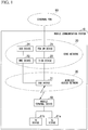
- FIG. 1 is a simplified block diagram showing the network configuration of a mobile communication system according to the first embodiment of the present invention.
- the mobile communication system 10 in this embodiment is connected to an external PDN (Packet Data Network) 50, and has a core network 20, a wireless access network 30, and at least one mobile terminal device 40.
- the mobile terminal device 10 has TE devices 41a and 41b that are connected to the mobile terminal device 40.
- EPS Packet Data Network
- the present invention is not limited in this manner, and can be applied in the same manner to a mobile communication system that has a node configuration.
- the core network 20 has a PDN-GW device 21, an MME (Mobile Management Entity) device 22, an S-GW device 23, and an HSS (Home Subscriber Server) device 24.
- the S-GW device 23 transmits and receives, as a local mobility anchor, packets from the ENB (eNodeB: base station device) 31 to which the mobile terminal device 40 is connected.
- ENB eNodeB: base station device
- the PDN-GW device 21 is connected to the external PDN 50, which is the Internet or an IMS (IP Multimeda Subsystem), and functions as a gateway that connects the core network 20 to these types of external PDNs 50.
- the PDN-GW device 21 allocates an IP address and performs sorting by packet QoS.
- the PDN-GW device 21 and the S-GW device 23 may be constituted on one and the same physical node.
- the MME (Mobility Management Entity) 22 is an entity that performs only signaling, and has as its main function management, including paging of mobility of the mobile terminal device 40 that connects to the wireless access network 30.
- the HSS device 24 performs user authentication and manages subscription data.
- Subscription data includes a subscriber's service subscription information, and whether the subscriber is subscribed to NEMO (Network Mobility) service.
- the wireless access network 30 has at least one ENB device 31, which is a base station.
- the mobile terminal device 40 is a device that has the functions of both an MT and a UE in UMTS.
- the TE devices 41a and 41b are TEs in UMTS.
- GTP General Packet Radio Service Tunneling Protocol
- GRE Generic Routing Encapsulation
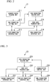
- FIG. 2 is a simplified block diagram showing the configuration of the PDN-GW 21 in the present embodiment.
- the PDN-GW 21 has an address block holding unit 211, a PDN connection setting unit 212, an S-GW connection interface unit 213, a PDN connection holding unit 214, a user data transfer unit 215, and a PDN connection interface unit 216.
- the S-GW connection interface unit 213 is a communication interface unit for performing communication connection with the S-GW device 23.
- Each unit of the PDW-GW device 21 performs communication with the S-GW device 23, via this S-GW connection interface unit 213.
- the PDN connection interface unit 216 is a communication interface unit for performing communication with the external PDN 50.
- Each unit of the PDN-GW device 21 performs communication with the external PDN 50, via this PDN connection interface unit 216.
- the address block holding unit 211 holds information indicating an address block that can be allocated to the PDN connection by the PDN connection setting unit 212, which is described later.
- An address block as used herein is a set of a plurality of addresses, and in the present embodiment is a network address in IPv4 (for example, 192.63.25.0/24 of 192.63.25.0 to 192.63.25.255) and an IPv6 prefix in IPv6 (for example, 1392:d38c::/32 of 1392:d38c:: to 1392:d38c:ffff:fff::).
- the PDN connection holding unit 214 stores information regarding a PDN connection, associating it with information that indicates an address block.
- the PDN connection in this case is a logical path used for transfer of user data, via the wireless access network 30, between the external PDN 50 and the mobile terminal device 40.
- There are two types of PDN connections a PDN connection for UE (PDN connection for a mobile terminal) for transferring user data of the mobile terminal device 40, and a PDN connection for a TE (PDN connection for an information terminal) for transferring user data of the information terminals 41a and 41b.
- the PDN connection setting unit 212 upon receiving a request from the mobile terminal device 40, allocates an address block to a TE PDN connection or a UE PDN connection, associates information that indicates the address block with information that indicates the TE PDN connection or the UE PDN connection and causes the PDN connection holding unit 214 to store the information, and transmits information indicating the allocated address block, addressing it to the mobile terminal device 40.
- the user data from the mobile terminal device 40 includes user data of the mobile terminal device 40, and user data of the information terminal devices 41a and 41b connected to the mobile terminal device 40.
- FIG. 3 is a simplified block diagram showing the configuration of the S-GW device 23 in the present embodiment.
- the S-GW device 23 has a PDN connection holding unit 231, a user data transfer unit 232, an ENODEB connection interface unit 233, a PDN-GW connection interface unit 234, a communication control unit 235, and an MME connection interface unit 236.
- the ENODEB connection interface unit 233 is a communication interface unit for performing communication connection to the ENB device 31. Each unit of the S-GW device 23 performs communication with the ENB device 31, via the ENODEB connection interface unit 233.
- the PDN-GW connection interface unit 234 is a communication interface unit for performing communication connection with the PDN-GW device 21. Each unit of the S-GW device 23 performs communication with the PDN-GW device 21, via the PDN-GW connection interface unit 234.
- the MME connection interface unit 236 is a communication interface unit for performing communication connection with the MME device 22. Each unit of the S-GW device 23 performs communication with the MME device 22, via the MME connection interface unit 236.
- the PDN connection holding unit 231 stores information regarding the PDN connection.
- the user data transfer unit 232 upon receiving user information from the mobile terminal device 40, via the END device 31, transfers it to the PDN-GW device 21, using the PDN connection that is stored by the PDN connection holding unit 231.
- the user data transfer unit 232 upon receiving the user data from the external PDN 50 via the PDN-GW device 21, transfers it to the ENB device 31, using the PDN connection that is stored in the PDN connection holding unit 231.
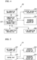
- FIG. 4 is a simplified block diagram showing the configuration of the MME device 22 in the present embodiment.
- the MME device 22 has an HSS connection interface unit 221, a communication control unit 222, an ENODEB connection interface 223, a location information holding unit 224, a subscriber information holding unit 225, and an S-GW connection interface unit 226.
- the HSS connection interface unit 221 is a communication interface unit for performing communication connection with the HSS device 24.
- Each unit of the MME device 22 performs communication with the HSS 24, via the HSS connection interface unit 221.
- the ENODEB connection interface unit 223 is a communication interface unit for performing communication connection with the ENB device 31.
- Each unit of the MME device 22 performs communication with the ENB device 31, via the ENODEB connection interface 223.
- the S-GW connection interface unit 226 is a communication interface unit for performing communication connection with the S-GW device 23.
- Each unit of the MME device 22 performs communication with the S-GW device 23, via the S-GW connection interface unit 226.
- the location information holding unit 224 holds location information that indicates what ENB device 31 it is possible for each mobile terminal device 40 to communication with.
- the subscriber information holding unit 225 (terminal information storage unit) holds subscription data that includes service subscription information indicating which of mobile terminal devices 40 are subscribed to which service, associated with information identifying each of the mobile terminal devices 40. In the present embodiment, this service includes NEMO (Network Mobility) service. Also, in the present embodiment, the subscription data includes a flag that indicates whether or not the mobile terminal device 40 has a router function.
- the location information and subscription data is the required data acquired by the MME device 22 from the HSS device 24.
- the communication control unit 222 controls communication of the MME device 22, and has a setting enabled/disabled judgment unit 227.
- the setting enabled/disabled judgment unit 227 upon receiving an attach request from the mobile terminal device 40 (request for a UE PDN connection setting), via the ENB device 31, makes a judgment as to whether the UE PDN connection that has been requested for setting can be set, based on a flag that indicates whether or not there is a router function being requested, and information included in the subscription data of the mobile terminal device 40 that indicates whether or not the mobile terminal device that originates the request is subscribed to the NEMO service. Details of this judgment are described later.
- the communication control unit 222 causes the subscriber information holding unit 225 to store the value of the flag that indicates whether or not a router function is provided.
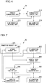
- FIG. 5 is a simplified block diagram showing the configuration of the HSS device 24 in the present embodiment.
- the HSS device 24 has an MME connection interface unit 241, a control unit 242, a location information holding unit 243, and a subscriber information holding unit 244.
- the MME connection interface unit 241 is a communication interface unit for performing communication connection with the MME device 22.
- Each unit of the HSS device 24 performs communication with the MME device 22, via the MME connection interface unit 241.
- the location information holding unit 243 holds location information of all the mobile terminal devices 40 that belong to the mobile communication system.
- the subscriber information holding unit 244 holds subscription data for all mobile terminal devices 40 that belong to the mobile communication system 10.
- the control unit 242 controls the overall HSS device 24.
- the control unit 242 also, in response to a request from the MME device 22, provides and updates location information held by the location information holding unit 243 and the subscription data held by the subscriber information holding unit 244.
- FIG. 6 is a simplified block diagram showing the configuration of the ENB device 31 in the present embodiment.
- the ENB device 31 has a wireless communication unit 311, a communication control unit 312, an S-GW connection interface unit 313, and an MME connection interface unit 314.
- the wireless communication unit 311 is a communication interface unit for performing communication connection with the mobile terminal device 40.
- Each unit of the ENB device 31 performs communication with the mobile terminal device 40, via the wireless communication unit 311.
- the communication control unit 312 controls communication in the ENB device 31.
- the S-GW connection interface unit 313 is a communication interface unit for performing communication connection with the S-GW device 23.
- Each unit of the ENB device 31 performs communication with the S-GW device 23, via the S-GW connection interface unit 313.
- the MME connection interface unit 314 is a communication interface unit for performing communication connection with the MME device 22.
- Each unit of the ENB device 31 performs communication with the MME device 22, via the MME connection interface unit 314.
- FIG. 7 is a simplified block diagram that shows the constitution of the mobile terminal device 40.
- the mobile terminal device 40 has a connection request unit 401, an address block storage unit 404, a router function unit 405, an address allocation unit 406, a wireless communication unit 407, and a TE connection wireless communication unit 408.
- the connection request unit 401 has an attach request unit 402 and a TE connection request unit 403.
- the wireless communication unit 407 is a communication interface for performing a communication connection with the ENB device 31.
- Each unit of the mobile terminal device 40 performs wireless communication with the ENB device 31, via this wireless communication unit 407.
- the TE connection wireless communication unit 408 is a communication interface for performing a communication connection with the TE devices 41a and 41b.
- Each unit of the mobile terminal device 40 performs communication with the TE devices 41a and 41b, via this wireless communication unit 408.
- the attach request unit 402 makes an attach request (UE PDN connection setting) to the core network 20, via the ENB device 31, and receives information that indicates the IP address (IPv4 address or IPv6 prefix) that is allocated to the UE PDN connection set by the request from the core network 20, via the ENB device 31.
- This request includes a flag that indicates that the mobile terminal device 40 has a router function (router function unit 405).
- Router function unit 405 The description of the subsequent communication that is performed between the mobile terminal device and the core network, via the ENB device 31, is omitted herein.
- the TE connection request unit 403 makes a TE PDN connection setting request to the core network 20, via the ENB device 31, and receives information that indicates the IP address (IPv4 network address or IPv6 prefix) that is allocated to the TE PDN connection set by the request from the core network 20, via the ENB device 31.
- IP address IPv4 network address or IPv6 prefix
- the address block storage unit 404 stores information that indicates the address blocks received by the attach request unit 402 and the TE connection request unit 403 of the connection request unit 401.
- the address allocation unit 406 allocates an address that belongs to the address block indicated by the information received by the TE connection request unit 403 to the TE device 41a.
- the router function unit 40 upon receiving the user data addressed to the address allocated to the TE devices 41a and 41b, transfers the received user data to the TE device to which the address is allocated.
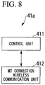
- FIG. 8 is a simplified block diagram showing the configuration of the TE device 41a in the present embodiment. Because the TE devices 41a and 41b have the same configuration, the description will be of the configuration of the representative TE device 41a.
- the TE device 41a has a control unit 411 and an MT connection wireless communication unit 412.
- the control unit 411 controls the overall TE device 41a.
- the MT connection wireless communication unit 412 is a communication interface unit for performing communication connection with a mobile terminal device 40 that has an MT function (modem function for making connection to the wireless access network 30).
- the control unit 411 performs communication with the mobile terminal device 40, via the MT connection wireless communication unit 412.
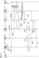
- FIG. 9 is a sequence diagram showing an example of the sequence of the mobile terminal device 40 attaching to the EPS.
- the attach request unit 402 of the mobile terminal device 40 transmits an attach request to the ENB device 31 (S901).
- This attach request includes therein subscriber identification information (IMSI: International Mobile Subscriber Identify) and user equipment function information (UE capability) that indicates the functions that the UE has.
- the user equipment function information includes an MR function capability (MR capability) flag that indicates the existence or non-existence of the MR (Mobile Router) function.
- MR capability MR function capability
- the mobile terminal device 40 sends the attach request with this flag set to valid.
- the ENB device 31 receives the above-noted attach request and transmits it to the MME device 22 (S902).
- the MME device 22 extracts the subscriber identification information included in the attach request and performs user authentication between the mobile terminal device 40 and the HSS device 24 (S903-1 to S903-3). If the user authentication succeeds, in order to acquire the service subscription status of the subscriber, the MME device 22 transmits to the HSS device 24 the location information update message that includes the subscriber identification information included in the attach request at sequence S902 (S904).
- the HSS device 24 Upon receiving the location information update message, the HSS device 24 transmits subscription data that indicates the specified contract information of the subscriber to the MME device 22 (S905).
- the MME device 22 verifies from the acquired subscription data whether the subscriber has contracted for the NEMO service and, in the case in which, in spite of not being subscribed to the NEMO service, the MR function is requested, an attach refusal is transmitted to the mobile terminal device 40, via the ENB device 31, and the attach sequence is interrupted (attach failure). Further, if necessary, a notification is given to the user by the mobile terminal device 40 to the effect that there is no subscription to the NEMO service.
- the mobile terminal device PDN connection establishment processing noted below as steps S906 and thereafter may be continuously performed, and at least communication performed by the mobile terminal device 40 may be permitted, regardless of whether or not there is a subscription to the NEMO service. In this case, however, the MME device 22. upon receiving the PDN connectivity request at step S1003 of FIG.
- the MME device 22 transmits the subscription data ACK (Insert Subscriber Data Ack) to the HSS device 24 (S906).
- the HSS device 24 completes the updating of the location information of the mobile terminal device 40 in response to a location information update message at sequence 904, and transmits a location information update ACK (Update Location Ack) to the MME device 22.
- the MME device 22 in order to establish a default EPS bearer between the S-GE device 23 and the PDN-GW device 21, transmits a Bearer Setup Request to the S-GW device 23.
- the Bearer Setup Request includes the subscriber's identification information, the IP address of the PDN-GW device 21, the APN, the PDN connection ID1, the PDN type 1, the PDN address 1, and the EPS bearer ID1.
- the APN Access Point Name uniquely defines the external PDN 50 to be connected, and the IP address of the PDN-GW device 21 and the APN are determined based on the subscription data acquired from the HSS device 24, and with regard to the APN, the mobile terminal device 40 may be explicitly indicated by including it in the attach request transmitted at S901.
- the PDN connection ID is an identifier for the purpose of distinguishing among a plurality of PDN connections that are established to one and the same PDN-GW device 21 within one and the same PDN, at least within the PDN-GW device 21.
- the PDN connection ID distinguishes among a plurality of PDN connections that are established from the mobile terminal device 40 to one and the same PDN-GW device 21 within one and the same PDN, and rather than this being an independent information element, by making this a new identifier that is appended, for example, to the end of one APN, it may identify the individual PDN connections of a plurality of PDN connections established with a mobile terminal device 40 within a PSN-GW device 21.
- the PDN address indicates the IPv4 address or the IPv6 prefix, or both, allocated to the PDN connection that is established.
- the NULL address (address not specified) is stored, and in the case in which there is specification within the above-noted subscription data, that address may be used.
- the PDN type indicates the IP address type of the PDN address, and it is possible to specify an IPv4 address or an IPv6 prefix, or both.
- the EPS bearer ID is an identifier that distinguishes among a plurality of EPS bearers established by one mobile terminal device 40.
- the S-GW device 23 receives the Bearer Setup Request and starts the protocol to establish an EPS bearer with the PDN-GW device 23.
- the S-GW device 23 transmits a Bearer Setup Request to the PDN-GW device 21 (S909).
- the Bearer Setup Request includes the subscriber's identification information, the S-GW device 23 IP address, the APN, the PDN connection ID1, the TEID1 for the S-GW, the PDN type 1, the PDN address 1, and the EPS bearer ID 1.
- the S-GW device 23 transmits a Proxy Binding Update message to the PDN-GW device 21 (S909).
- the Proxy Binding Update includes the mobile network access identifier (MN_NA1: Mobile Node Network Access Identifier) generated from the identification information, the APN, the PDN connection ID1, the downlink GRE key 1, the PDN type 1, and the PDN address 1.
- MN_NA1 Mobile Node Network Access Identifier
- the PDN-GW device 21 upon receiving the Bearer Setup Request or the Proxy Binding Update at sequence S909, sets the PDN connection 1 (S910).
- the PDN-GW device 21 first, in the case in which a specific ID address has not been set in the PDN address 1 received at sequence S909, allocates an IPv4 address 1, an IPv6 prefix, or both to the PDN address 1. This PDN address is then allocated to the PDN connection 1. Additionally, a default EPS bearer that is associated with the PDN connection 1 is established, and a user packet addressed and transferred to this PDN address 1 is linked to the above-noted EPS bearer that has been established.
- the PDN-GW device 21 returns to the S-GW device 23 either a bearer setup response or a Proxy Binding Acknowledgment (S911).
- the bearer setup response includes the TEID1 for the PDN-GW of the set PDN connection, the PDN type 1, the PDN address 1, and the EPS bearer ID1.
- the Proxy Binding Acknowledgment is used and mobile network access identifier for the set PDN connection, the PDN connection ID1, the uplink GRE key 1, the PDN type 1, and the PDN address 1 are included within this message.
- the PDN-GW device 21, using the EPS bearer 1 starts transmitting to the S-GW device 23 the user packet that was addresses to the PDN address 1 allocated to the PDN connection 1 set at sequence S910 (S912).
- the S-GW device 23 upon receiving the Proxy Binding Acknowledgment or the bearer setup response at sequence S911, associates and records in a management table (PDN connection holding unit 231) the PDN address 1 of these messages, the subscriber identification information, and the MME device 22, and also transmits the Bearer Setup Response to the MME device 22 (S913).
- the bearer setup response includes the IP address of the S-GW device 23 of the set PDN connection 1, the TEID1 for the S-GW, the PDN type 1, the PDN address 1, and the EPS bearer ID1.
- the S-GW device 23 begins buffering the user packet transferred from the PDN-GW device 21.
- the MME device 22 receives the bearer setup response, and transmits an Attach Accept to the ENB device 31 (S914).
- This Attach Accept includes the ID address of the S-GW device 23 that received by the Bearer Setup Request, the APN, the PDN connection 1, the TEID1 for the S-GW, the PDN type 1, the PDN address 1, and the EPS bearer ID1.
- the ENB device 31 transmits to the mobile terminal device 40 the APN that received the Attach Accept as sequence S914, the PDN connection ID1, the PDN type 1, the PDN address 1, and the EPS bearer ID1 (S915).
- the mobile terminal device 40 upon receiving the Attach Accept, acquires the PDN type 1 and PDN address 1 included in the received Attach Accept, and also transmits to the ENB device 31 an Attach Complete that includes the EPS bearer ID1 included in the received Attach Accept (S916). Additionally, the mobile terminal device 40 transitions to a state in which user data can be transmitted and received.
- the mobile terminal device 40 uses the PDN address acquired from the Attach Accept at sequence S915 as the transmitting address of origin to transmit the user data addressed to the external PDN 50, the user data is transferred by the bearer 1 within the established PDN connection 1 and, after transmission of the user data up to the PDN-GW device 21, transmission is made to the external PDN 50 (S918).
- the MME device 22 upon receiving the Attach Complete at sequence S917, transmits to the S-GW device 23 a bearer update request that includes the IP address of the ENB device 31 included in this Attach Complete, the TEID1 for the ENB, and the EPS bearer ID1 (S919).
- the S-GW device 23 upon receiving this bearer update request, acquires the IP address of the ENB device 31 included in the bearer update request, that is the IP address of the ENB device 31 to which the mobile terminal device 40 is connected, and returns to the MME device 22 the bearer update request that includes the IP address of the ENB device 31 that was included in the received bearer update request (S920).
- the S-GW device 23 has acquired the IP address of the ENB device 31 to which the mobile terminal device 40 is connected, transmission to the ENB device 31, including the buffered part directed at the mobile terminal device 40 that was transferred from the PDN-GW 21, and the ENB device 31 transmits that user packet to the mobile terminal device 40 (S921).
- the above completes the attachment of the mobile terminal device 40 to the EPS.
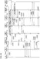
- FIG. 10 is a sequence diagram that shows an example of the sequence of connection of the TE device 41a and the TE device 41b to the mobile terminal device 40.
- the TE device 41a places the wireless communication interface unit 412 into the active state, and starts the IP address allocation protocol.
- the IP address allocation protocol may be an IPv6 Stateless Auto Configuration (IETF RFC 4862) or a DHC Pv4 (IETF RFC 2462) or a DHCPv6 (IETF RFC 3315), and is further not limited to these.
- the description herein uses the example of using the IPv6 Stateless Auto Configuration.
- the TE device 41a sends an RS (Router Solicitation) (S1001).
- the mobile terminal device 40 receives the RS from the TE device 41a and if the mobile terminal device 40 itself has transitioned to the idle (IDLE) state within the EPS, it transitions to the active state in order to perform transmission and reception of communication data (S1002) (refer to TS 23.401, the 3GPP specifications).
- S1002 transmission and reception of communication data
- the TE connection request unit 403 of the mobile terminal device 40 transmits a PDN Connectivity Request to the MME device 22 to the ENB device 31 (S1003).
- the PDN Connectivity Request includes an APN and an MNP (Mobile Network Prefix) type (address block type).
- the APN used is what was acquired from the Attach Accept received from the ENB device 31 in the attach sequence shown in FIG. 9 and, similar to the case of sending the Attach Request at S901, the mobile terminal device 40 may be explicitly indicated.
- the MNP type is for specifying the address type of the network address (address block) allocated to the PDN connection that is established, and this is either an IPv4 type, which is an address block specified by an IPv4 (Internet Protocol Version 4) network address, or a IPv6 type, which is an address block specified by an IPv6 (Internet Protocol Version 6) prefix, or specified as both.
- this MNP type may be a new address type that extends the PDN type used in the attach sequence of FIG. 9 , and may be specified in combination with the PDN type.
- the communication control unit 222 of the MME device 22 receives the PDN Connectivity Request and, in order to establish the PDN connection 2, transmits a Bearer Setup Request to the S-GW device 23 (S1004). However, in the case in which the attach processing is continued with the MR function at sequence S906 of FIG. 9 remaining disabled, a PDN Connectivity Refusal is returned to the mobile terminal device 40, and the connection sequence is terminated.
- the Bearer Setup Request includes, in addition to the APN and MNP type that are included in the PDN Connectivity Request at sequence S1003, the subscriber identification data, the IP address of the PDN-GW device 21, the PDN connection ID2, the MNP1, and the EPS bearer ID2.
- the MNP Mobile Network Prefix
- the communication control unit 222 stores a NULL address (address not specified).
- the mobile terminal device 40 that is the source of the request within the subscription data acquired from the HSS device 24 during the attach procedure of FIG. 9 and stored in the subscriber information holding unit 225 is associated with the information to be identified, and in which the MNP, which is information indicating an address block allocated to the TE PDN connection is specified, that value is stored in the MNP in this Bearer Setup Request (each of the IPv4 sub-network address 2 and the IPv6 prefix 2).
- the S-GW device 23 receives the Bearer Setup Request at sequence S1004, and begins the procedure for establishing a default EPS bearer for the TE device 41a with the PDN-GW device 21.
- the S-GW device 23 transmits the Bearer Setup Request to the PDN-GW device 21 (S1005).
- This Bearer Setup Request includes the subscriber identification information, the IP address of the S-GW device 23, the APN, the PDN connection ID2, the TEID2 for the S-GW, the MNP type, MNP1, and the EPS bearer ID2. This is different from the Bearer Setup Request at sequence S909 in FIG. 9 in that the MNP type 1 and the MNP1 are included in place of the PDN type 1 and the PDN address 1.
- the S-GW device 23 transmits a Proxy Binding Update message to the PDN-GW device 21.
- the Proxy Binding Update message includes the mobile network access identifier generated from the subscriber identification information, the APN, the PDN connection ID1, the downlink GRE key, the MNP type 1, and the MNP1.
- This Proxy Binding Update also differs from the Proxy Binding Update at sequence S909 of the sequence in FIG. 9 in that the MNP type 1 and the MNP1 are included in place of the PDN type 1 and the PDN address 1.
- the PDN connection setting unit 212 of the PDN-GW device 21 receives a Bearer Setup Request or a Proxy Binding Update at sequence S1005, and begins the setting of the PDN connection 2 (S1006).
- the PDN connection setting unit 212 in the case in which a specific IPv4 sub-network address and a specific IPv6 prefix are not specified in the MNP1, allocates, from the address block pool held by the address block holding unit 211, an address block of the type specified by the MNP1 of the Bearer Setup Request or the Proxy Binding Update, that is, an IPv4 sub-network address 2 or IPv6 prefix 2 or both to the MNP1.
- the PDN connection 2 is then allocated to the MNP1.
- a default EPS bearer 2 that is associated with the PDN connection 2 is established.
- the PDN connection setting unit 212 causes the PDN connection holding unit 214 to store information indicating the address block allocated to the MNP1 and information regarding the PDN connection 2.
- the user data transfer unit 215 joins user data addressed to the MNP1 from the external PDN 50 to the above-noted EPS bearer 2 that has been established. Addressing to the MNP1 indicates that the user data allocated to the address belonging to the address block of the MNP 1.
- the PDN-GW device 21 returns to the S-GW device 23 either a bearer setup response or a Proxy Binding Acknowledgment (S1007).
- the bearer setup response is used at this sequence S1007, and the bearer setup response includes the TEID2 for the PDN-GW, MNP1, and the EPS bearer ID2.
- the Proxy Binding Acknowledgement is used, and the message includes therein the mobile network access identifier, the PDN connection ID2, the uplink GRE key 2, the MNP type 1, and MNP1.
- the transfer of the user packet addressed to MNP1 from the external PDN 50 up to the S-GW device 23 is started (S1008).
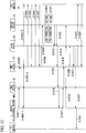
- FIG. 11 is a flowchart showing the packet transfer of the PDN-GW device 21.
- the PDN-GW device 21 upon receiving a packet from the external PDN 50 (Sa1), checks the addressee of the packet (Sa2).
- the PDN-GW device 21 judges whether or not the destination of the packet is MNP1 (refer to sequence S1004 in FIG. 10 ) (Sa3), and if this is the case (YES at Sa3), selects the default EPS bearer (bearer between the external PDN 50 and the TE device 41a) corresponding to MNP1 (Sa4), after which it transitions to step Sa5.
- step Sa3 if the judgment is that there is no agreement (NO at Sa3), transition is made to step Sa6, and the PDN-GW 21 judges whether the destination of the packet agrees with the PDN address 1 (refer to sequence S908 in FIG. 9 ) (Sa6) and, if the judgment is that there is agreement (YES at Sa4), after selecting the default EPS bearer (bearer between the external PDN 50 and the mobile terminal device 40) of the PDN connection 1 corresponding to the PDN address 1, transition is made to step Sa5.
- the default EPS bearer bearer between the external PDN 50 and the mobile terminal device 40
- the S-GW device 23 associates MNP1, the subscriber identification information, and the MME device 22 and stores them in a management table (PDN connection holding unit 231), and also transmits a bearer setup response to the MME device 22 (S1009).
- the bearer setup response includes the IP address of the S-GW device 23, the TEID2 for the S-GW, the MNP type 1, MNP1, and the EPS bearer ID2.
- the S-GW device 23 begins buffering the user packet addressed to MNP1 transferred from the PDN-GW device 21.
- the MME device 22 receives the bearer setup response, and transmits a PDN Connectivity Accept to the ENB device 31 (S1010).
- the PDN Connectivity Accept includes the IP address of the S-GW device 23, the APN, the PDN connection ID2, the TEID2 for the S-GW, the MNP type 1, MNP1, and the EPS bearer ID2.
- the ENB device 31 that receives the PDN Connectivity Accept transmits to the mobile terminal device 40 a PDN Connectivity Accept that includes the APN, the PDN connection ID2, the MNP type 1, MNP1, and the EPS bearer ID2 (S1011).
- the mobile terminal device 40 receives the PDN Connectivity Accept, acquires the MNP type 1 and MNP1, and transmits to the ENB device 31 an RRC Connection Reconfiguration Complete that includes the EPS bearer ID2 (S1012).
- the ENB device 31 upon receiving the RRC Connection Reconfiguration Complete, transmits to the MME device 22 a bearer setup response that includes the IP address of the ENB device 31, the TEID2 for the ENB, and the EPS bearer ID2 (S1013).
- the MME device 22 upon receiving the bearer setup response, transmits to the S-GW device 23 a Bearer Update Request that includes the IP address of the ENB device 31, the TEID2 for the ENB, and the EPD bearer ID2 (S1014).
- the S-GW device 23 Upon receiving the Bearer Update Request, the S-GW device 23 returns to the MME device 22 a Bearer Update Request that includes the EPS bearer ID2 (S1015).
- the S-GW device 23 acquires the IP address of the ENB device 31 to which the TE device 41a is connected from the Bearer Update Request of sequence S1014, the transfer to the ENB device 31 of the part of the user packet addressed to the TE device 41a that has been transferred from the PDN-GW device 21 and buffered is also begun, and the ENB device 31 transfers that user packet to the mobile terminal device 40 (S1016).
- the mobile terminal device 40 that transmitted the RRC Connection Reconfiguration Complete to the ENB device 31 at sequence S1012 uses the acquired MNP1 to allocate an IP address to the TE device 41a.
- the IPv6 prefix 2 set into MNP 1 is set, it would be similar in the case in which the IPv4 sub-network address is set. Also, when both the IPv4 sub-network address and the IPv6 prefix 2 are set, one of the protocols supported by the TE device 41a is selected and used.
- the mobile terminal device 40 generates an RA (Router Advertisement) that sets the IPv6 prefix 2, and transmits this to the TE device 41a (S1017).
- the TE device 41a upon receiving the Router Advertisement, extracts the IPv6 prefix 2 from the Router Advertisement and automatically generates an IPv6 address. Also, DAD (Duplicate Address Detection) with respect to the generated address is performed with the mobile terminal device 40 to verify that the generated address is unique (S1018).
- RA Router Advertisement
- DAD Downlicate Address Detection
- the TE device 41a verifies by duplicate address detection that the IPv6 address is unique, it becomes possible to transmit and receive user data via the MT connection wireless communication unit 412.
- the user packet addressed to MNP1 and transferred from the PDN-GW 21 is transferred up to the mobile terminal device 40 via the S-GW device 23 and the ENB device 31, and the mobile terminal device 40 transfers it to the TE device 41a via the TE connection wireless communication unit 408 (S1019).
- the routing function of the mobile terminal device 40 routes the user data in accordance with the transmission destination address of the user data.
- the transmission destination address is MNP1 or the mobile terminal device 40 itself
- the mobile terminal device 40 transfers it directly to the addressee.
- the user data is transferred to the EPS bearer within the established PDN connection 2, and is transferred up to the PDN-GW device 21 and transmitted to the external PDN 50 by the PDN-GW device 21 (S1020).
- the MME device 22 after receiving the Bearer Update Response of the sequence S1015, transfers the Location Information Update Request to the HSS device 24 (S1021).
- This Location Information Update Request includes information of the established PDN connection 2, and includes the APN, the PDN connection ID2, the IP address of the PDN-GW device 21, the MNP type 1, and MNP1.
- the HSS device 24 upon receiving this Location Information Update Request it stores this information into the subscriber's subscription data, so that when the mobile terminal device 40 re-attaches to the EPS and performs a PDN Connectivity Request, when the power is turned on or off, or the like, the same MNP1 is allocated.
- the HSS device 24 also transmits the Location Information Update Request to the MME device 22 (S1022).
- the mobile terminal device 40 when a TE device 41a is connected anew to the mobile terminal device 40 and transmits a Router Solicitation (S1023), the mobile terminal device 40, without establishing a new PDN connection, performs allocation of an IP address, using the MNP1 that had already been acquired for the TE device 41a. That is, similar to the case of sequence S1017, the mobile terminal device 40 transmits to the TE device 41b a Router Advertisement that sets the IPv6 prefix 2 (S1024).
- the TE device 41b upon receiving the Router Advertisement, executes the generation of an IP address and Duplicate Address Detection (S1025), similar to the TE device 41a, and transmitting and receiving user data with the external PDN 50 becomes possible (S1026, S1027).
- the sequences S1023 to S1025 are applied to every TE from the second and subsequent units.
- the mobile terminal device 40 After the TE device 41a connects to the mobile terminal device 40, without waiting for the RRC Connection Reconfiguration Complete (sequence S1012) of the mobile terminal device 40, in the case in which the TE device 41b has connected to the mobile terminal device 40, the mobile terminal device 40, without performing a PDN Connectivity Request anew, waits for the PDN Connectivity Accept of sequence S1011, and transmits to the TE device 41b the Router Advertisement that sets the MNP1 for which notification was made by the PDN Connectivity Accept.
- the IPv4 sub-network address 2, the IPv6 prefix, or both, which are acquired from MNP1 at the sequence S1011 are recorded as the address pool in the DHCP server within the mobile terminal device 40, and a DHCP Offer (IP address provision notification) that includes the allocated IP address is transmitted to the TE that has sent the DHCP Request (IP address allocation request notification).
- IP address provision notification IP address provision notification
- the mobile terminal device 40 acquires one address block (one IPv6 prefix or one IPv4 sub-network address, or both), and shares it with a plurality of TEs that are connected to the mobile terminal device 40.
- one address block one IPv6 prefix or one IPv4 sub-network address, or both
- shares it with a plurality of TEs that are connected to the mobile terminal device 40.
- the communication system of the present embodiment allocates one PDN connection and provides a connection to the external PDN 50 to a plurality of TEs (TE devices 41a and 41b) connected to the one mobile terminal device 40 that functions as both a UE and an MT. By doing this, it is possible to reduce the overall communication system administrative information, and to reduce the number of signaling messages.
- FIG. 12 is a simplified block diagram showing the configuration of the mobile terminal device 40a in the present embodiment.
- the mobile terminal device 40a has a connection request unit 401a, an address block storage unit 404, a router function unit 405, an address allocation unit 406, a wireless communication unit 407, and a TE connection wireless communication unit 408. Elements in this drawing that correspond with elements in FIG. 7 are assigned the same reference numerals, and the description thereof is omitted.
- the connection request unit 401a has an attach request unit 402a.
- the attach request unit 402a when sending an Attach Request to the core network 20 via the ENB device 31, includes a request for PDN connection setup. By this request, the attach request unit 402a receives from the core network 20, via the ENB device 31, the IP address and information indicating the address block allocated to the PDN connection for the TE (IPv4 network address or IPv6 prefix).
- FIG. 13 is a drawing showing an example of the sequence of attaching the mobile terminal device 40a to the EPS in the present embodiment. Because from sequence S1401 to S1407 is the same as from sequence S901 to S907 in the first embodiment ( FIG. 9 ), the description thereof will be omitted. After completion of S1407, the MME device 22 transmits a Bearer Setup Request to the S-GW device 23 for the purpose of establishing a default EPS bearer (S1408).
- this Bearer Setup Request includes, in addition to the subscriber identification information and the IP address of the PDN-GW device 21, the APN, the PDN connection ID1, the PDN type 1, the PDN address 1, and the EPS bearer ID1 for establishing the PDN connection 1 for the UE, and the APN, the PDN connection ID2, the MNP type 1, MNP, and EPS bearer ID2 for establishing the PDN connection 2 for the TE.
- the PDN connection ID is an identifier that is independent from the APN, one APN only may be included.
- the S-GW device 23 receives the Bearer Setup Request, and starts the procedure for establishing the default EPS bearer with the PDN-GW device 21.
- the S-GW device 23 transmits a Bearer Setup Request to the PDN-GW device 21 (S1409).
- This Bearer Setup Request includes the subscriber identification information, the IP address of the S-GW device 23, the APN and PDN connection ID1, the TEID1 for the S-GW, the PDN type 1, the PDN address 1, the EPD bearer ID1, the APN and PDN connection ID2, the TEID2 for the S-GW, the MNP type 1, MNP1, and the EPS bearer ID2.
- the S-GW device 23 transmits to the PDN-GW device 21 a Proxy Binding Update message.
- the Proxy Binding Update message includes the mobile communication network access identifier, the APN and PDN connection ID1, the downlink GRE key 1, the PDN type 1, the PDN address 1, and the EPS bearer ID1, and the APN and PDN connection ID2, the downlink GRE key 2, the MNP type 1, MNP 1, and the EPS bearer ID2.
- the PDN-GW device 21 receives the Bearer Setup Request or Proxy Binding Update of the sequence S1409, and starts the setup of the PDN connection 1 and the PDN connection 2 (S1410 and S 1411).
- the PDN connection 1 setup method of the sequence S1410 is in accordance with S910 of the first embodiment.
- the PDN connection 2 setup method of the sequence S 1411 is in accordance with S1006 of the first embodiment.
- the PDN-GW device 21 When the setup of the PDN connection 1 and the setup of the PDN connection 2 are completed, the PDN-GW device 21 returns a Bearer Setup Response or a Proxy Binding Acknowledgment to the S-GW device 23 (S1412).
- the Bearer Setup Response is used in the sequence S1412, and the Bearer Setup Response includes the TEID1 for the PDN-GW, the PDN type 1, the PDN address 1, and the EPS bearer ID1 for the PDN connection 1, and the TEID2 for the PDN-GW, the MNP type 1, MNP1, and the EPS bearer ID2 for the PDN connection 2.
- the Proxy Binding Acknowledgment includes the mobile network access identifier, the PDN connection ID1, the uplink GRE key 1, the PDN type 1, the PDN address 1, the PDN connection ID2, the uplink GRE key 2, the MNP type 1, and MNP1.
- the PDN-GW device 21 begins transfer up to the S-GW device 23 of a user packet addressed to the PDN address 1 from the external PDN 50, using the established EPS bearer 1. Also, transfer up to the S-GW device 23 of the user packet addressed to MNP1 from the external PDN 50 begins, using the established EPS bearer 2 (S1413).
- the S-GW device 23 associates and records in a management table (PDN connection holding unit 231) the PDN address 1, MNP1, the subscriber identification information, and the MME device 22, and also transmits the Bearer Setup Response to the MME device 22 (S1414).
- the Bearer Setup Response includes the IP address of the S-GW device 23, the TEID1 for the S-GW, the PDN type 1, the PDN address 1, and the EPS bearer ID1 for PDN connection 1, and the TEID2 for the S-GW, the MNP type 1, MNP1 and the EPS bearer ID2 for PDN connection 2.
- the S-GW device 23 begins buffering the user packets transferred from the PDN-GW device 21 addressed to the PDN address 1 and addressed to MNP1 (S1413).
- the MME device 22 receives the Bearer Setup Response, and transmits an Attach Accept to the ENB device 31 (S 1415).
- the Attach Accept includes the IP address of the S-GW device 23, the APN, the PDN connection ID1, the TEID1 for the S-GW, the PDN type 1, the PDN address 1, and the EPS bearer ID1 for the PDN connection 1, and the APN, the PDN connection ID2, the TEID2 for the S-GW, the MNP type 1, MNP1, and the EPS bearer ID2 for the PDN connection 2.
- the ENB device 31 transmits to the mobile terminal device 40a an Attach Accept that includes the APN, the PDN connection ID1, the PDN type 1, the PDN address 1, and the EPS bearer ID1 for the PDN connection 1, and the APN, the PDN connection ID2, the MNP type 1, MNP1, and the EPS bearer ID2 for the PDN connection 2 (S1416).
- the mobile terminal device 40a receives the Attach Accept, acquires the PDN type 1, the PDN address 1, the MNP type 1, and MNP1 included therein, and transmits to the ENB device 31 an Attach Complete that includes the EPS bearer ID1 and the EPS bearer ID2 (S1417).
- the mobile terminal device 40a also transitions to the state in which user data can be transmitted and received.
- the ENB device 31 receives the Attach Complete, and transmits to the MME device 22 an Attach Complete that includes the IP address of the ENB device 31, the TEID1 for the ENB, the EPS bearer ID1, the TEID2 for the ENB, and the EPS bearer ID2 (S1418).
- the mobile terminal device 40a transmits user data addressed to the external PDN 50, after the user data is transferred up to the PDN-GW device 21, using the EPS bearer 1 within the established PDN connection 1, it is sent to the external PDN 50 (S1419).
- the MME device 22 transmits to the S-GW device 23 a Bearer Setup Request that includes the IP address of the ENB device 31, TEID1 for the ENB, the EPS bearer ID1, TEID2 for the ENB, and the EPS bearer ID2 (S1420).
- the S-GW device 23 returns to the MME device 22 a Bearer Update Response that includes the EPS bearer ID1 and the EPS bearer ID2 (S1421).
- the S-GW device 23 that has received the Bearer Update Request of sequence S1420 acquires the IP address of the ENB device 31 to which the mobile terminal device 40a is connected from the Bearer Update Request, and begins to transfer to the ENB device 31a user packet transferred from the PDN-GW device 21 to the mobile terminal device 40a and to the TE device 41a (addressed to MNP1) that had been buffered, and the ENB device 31 transmits that user packet to the mobile terminal device 40a (S 1422).
- the mobile terminal device 40a that transmitted the Attach Complete at sequence S 1417 to the ENB device 31 begins the allocation (Router Advertise transmission) of the IP address to the TE device 41a, using the IPv4 sub-network address 2 and the IPv6 prefix 2 set into the MNP1 of the Attach Accept in the sequence S1416 (S1423).
- the MME device 22 after receiving the Bearer Update Request of sequence S1421, transmits a Location Information Update Request to the HSS device 24 (S1424).
- This Location Information Update Request includes information of the established PDN connection 1 and PDN connection 2, which includes the address of the PDN-GW device 21, the APN, the PDN connection ID 1, the PDN type 1, and the PDN address 1 as PDN connection 1 information, and the APN, the PDN connection ID2, the MNP type 1, and MNP1 as the PDN connection 2 information.
- the HSS device 24 stores this information into the subscriber's subscription data, and when the power to the mobile terminal device 40a is turned on or off, or the like, so that the mobile terminal device 40a attaches once again to the EPS, the same MNP1 is allocated.
- the HSS device 24 also transmits a Location Information Update Acknowledgment (Update Location Ack) to the MME device 22 (S 1425).
- the mobile communication system 10b in the present embodiment has a configuration similar to that of the mobile communication system 10 of the first embodiment, although it differs in that, in place of the PDN-GW device 21, it is provided with a PDN-GW device 21b, and that, in place of the mobile terminal device 40, it is provided with a mobile terminal device 40b.
- the DHCP Dynamic Host Configuration Protocol
- IETF RFC 3633 IETF RFC 3633
- FIG. 14 is a simplified block diagram showing the configuration of the PDN-GW device 21b in the present embodiment.
- the PDN-GW device 21b in the present embodiment is the PDN-GW device 21 shown in FIG. 2 with the addition of a DHCP server unit 217.
- the DHCP server unit 217 upon receiving an address block request using the DHCP, allocates an address block to the PDN connection for the TE of the mobile terminal device 40b originating the request, and send this to the mobile terminal device 40b.
- GRE is used as the tunneling protocol for implementing an EPS bearer between the S-GW device 23 and the PDN-GW device 21b
- the S-GW device 23 has a DHCP relay function (not shown).
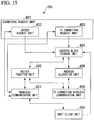
- FIG. 15 is a simplified block diagram showing the configuration of the mobile terminal device 40b in the present embodiment.
- the mobile terminal device 40b in the present embodiment is the mobile terminal device 21 with the addition of a DHCP client unit 409.
- the DHCP client unit 409 uses a dynamic host setup protocol to request an address block from the PDN-GW device 21b, and receives from the PDN-GW device 21b information that indicates the address block allocated to the PDN connection for the TE by the request.
- FIG. 16 is a sequence diagram showing an example of the connection sequence of the mobile terminal device 40b in the present embodiment.
- the sequence shown in FIG. 16 is a sequence that is started by the mobile terminal device 40b after the sequence S1012 of FIG. 10 .
- the mobile terminal device 40b after transmitting to the ENB device 31 an RRC Connection Reconfiguration Complete of sequence S1012, rather than using MNP1 that is acquired at sequence S1011. starts the DHCP sequence indicated below for acquiring the address block anew.
- the DHCP client 409 of the mobile terminal device 40b first, to find the DHCP server, transmits a DHCP Solicit message by a link-local broadcast transmission (S1101).
- a link-local broadcast transmission S1101
- the S-GW device 23 receives the DHCP Solicit message and transfers it to the PDN-GW device 21b, using the DHCP relay function.
- GTP link-local broadcast transmission
- a DHCP Request message in which is stored the IPv6 prefix length (in this case 48) for which allocation is desired is transmitted to the DHCP server unit 217 of the PDN-GW device 21b (S1103).
- the DHC server unit 217 of the PDN-GW device 21b receives the DHCP Request message from the mobile terminal device 40b and extracts the IPv6 prefix 3, which corresponds to the requested prefix length (provisionally 2001:1000::/48) from the address pool stored by the address block holding unit 214 of the corresponding device and assigns it to the PDN connection 2.
- the MNP1 that was assigned to the PDN connection 2 at sequence S1006 is released and returned to the address pool that is managed by the PDN-GW device 21b, the new IPv6 prefix 3 is allocated to MNP1, and the setting is made so that a user packet directed at the IPv6 prefix 3 from the external PDN 50 is linked to the EPS bearer 2, and transferred up to the S-GW device 23 (S1104).
- the DHCP server unit 217 of the PDN-GW device 21b stores the IPv6 prefix 3 in the DHCP Reply message, and transmits it to the mobile terminal device 40b (S1105).
- the S-GW device 23 receives the DHCP Reply message, similar to the case of the PDN-GW device 21b, the MNP1 that had been allocated to the PDN connection 2 is updated and the IPv6 prefix 3 is allocated, and the DHCP Reply message is transferred to the mobile terminal device 40b.
- the DHCP client unit 409 of the mobile terminal device 40b acquires the DHCP Reply message and, using the allocated IPv6 prefix 3, allocates an address to the mobile terminal device 40b, similar to sequences S1017 and S1018 of the first embodiment ( FIG. 10 ).
- the mobile communication system 10 in the present embodiment is a configuration similar to that of the mobile communication system 10 of the first embodiment, although it differs in that, in place of the PDW-GW device 21, it is provided with a PDN-GW device 21c, and that, in place of the mobile terminal device 40, it is provided with a mobile terminal device 40c.
- a mobile terminal device 40c By doing this, in contrast to the first embodiment, in which one IPv4 sub-network address or one IPv6 prefix or both are assigned to a plurality of TEs and the plurality of TEs share one PDN connection, in the present embodiment while an IPv6 prefix is shared by a plurality of TEs, different PDN connections are used for each TE.
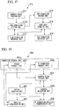
- FIG. 17 is a simplified block diagram showing the configuration of the PDN-GW device 21c.
- the PDN-GW device 21c has an address block holding unit 211, a PDN connection setup unit 212c, an S-GW connection interface unit 213, a PDN connection holding unit 214, a user data transfer unit 215, and a PDN connection interface unit 216.
- the descriptions of reference numerals in this drawing that are the same as in FIG. 2 (211 and 213 to 216) have been omitted.
- the PDN connection setup unit 212c performs the same type of setup of the PDN connection for the UE as the PDN connection setup unit 212.
- the PDN connection setup unit 212c upon receiving a request for the setup of a PDN connection for the TE from the mobile terminal device 40c, associates an address belonging to the address block allocated to the PDN connection for the TE with information regarding the PDN connection for the TE, causes the PDN connection holding unit 214 to store these, and transmits the allocated address to the mobile terminal device 40c.
- FIG. 18 is a simplified block diagram showing the configuration of the mobile terminal device 40c.
- the mobile terminal device 40c has a connection request unit 401c, an address block storage unit 404, a router function unit 405, an address allocation unit 406c, a wireless communication unit 407, and a TE connection wireless communication unit 408.
- the connection request unit 401c has an attach request unit 402 and a TE connection request unit 403c.
- the descriptions of reference numerals in this drawing that are the same as in FIG. 7 (402, 404, 405, 407, and 408) have been omitted.
- the TE connection request unit 403c upon receiving a connection request from the TE devices 41a and 41b, request the core network 20 to setup a TE PDN connection, and receives as a response to the request information that indicates the address that was allocated to the PDN connection for the TE.
- the TE connection request unit 403c causes the received address to be stored in the address block storage unit 404.
- the address allocation unit 406c allocates the address stored in the address block storage unit 404, that is, the address received by the PDN connection request unit 403c to the TE devices 41a and 41b.
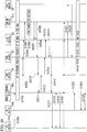
- FIG. 19 is a sequence diagram showing an example of the sequence of the connection for the TE devices 41a and 41b performing communication with an external PDN 50.
- the sequence starts from the condition in which the sequence shown in FIG. 9 of attachment of the mobile terminal device 40c to the EPS in the first embodiment has already been completed.
- the TE device 41a places the MT connection wireless communication unit 412 in the active state, the IP address is allocated and the protocol is started. This description is for the case in which IPv6 Stateless Auto Configuration is sued as the IP address allocation protocol.
- the TE device 41a in order to search for the default router, transmits a Router Solicit (S1201).
- the mobile terminal device 40c receives the Router Solicit from the TE device 41a and if the mobile terminal device 40c itself has transitioned to the idle state within the EPS, transitions to the active state in order to transmit and receive communication data (S1202) (refer to TS 23.401, the 3GPP specifications).
- the lower-order 64 bits of the link-local address that was the origin of the Router Solicit (automatically generated by the TE device 41a, using the MAC address of the MT connection wireless communication unit 412) is held as the interface ID1 of the TE device 41.
- a PDN Connectivity Request is transmitted to the MME device 22 (S1203).
- This PDN Connectivity Request includes the APN, the MNP type 1, and the interface ID1 of the TE device 41 acquired as noted above.
- the MME device 22 receives the PDN Connectivity Request and, to establish a PDN connection anew, transmits a Bearer Setup Request to the S-GW device 23 (S1204).
- the Bearer Setup Request includes, in addition to the APN and MNP type 1 included in the PDN Connectivity Request of sequence S1203, the subscriber identification information, the IP address of the PDN-GW device 21c, the PDN connection ID2, MNP1, the interface ID1, and the EPS bearer ID2.
- the MNP and the interface ID may not be independent data elements.
- the upper-order 64 bits of one information element may be used as the upper-order 64 bits of the MNP, and the lower-order 64 bits may be used as the interface ID.
- the S-GW device 23 receives the Bearer Setup Request and begins the procedure for establishing the default EPS bearer for the TE device 41a with the PDN-GW device 21c. In the case in which GTP is used as the protocol for implementing the EPS bearer, the S-GW device 23 transmits the Bearer Setup Request to the PDN-GW device 21c (S1205).
- the Bearer Setup Request includes the subscriber identification information, the IP address of the S-GW device 23, the APN, the PDN connection ID2, the TEID2 for the S-GW, the MNP type 1, MNP1, the interface ID1, and the EPS bearer ID2.
- the S-GW device 23 transmits a Proxy Binding Update message to the PDN-GW device 21c.
- the Proxy Binding Update message includes the mobile network access identifier, the APN, the PDN connection ID2, the downlink GRE key 2, the MNP type 1, MNP1, and the interface ID1.
- the PDN-GW device 21c receives the Bearer Setup Request of the sequence S1205 and starts the setup of the PDN connection 2 (S1206).
- the PDN-GW device 21c allocates the IPv6 prefix 2 to the MNP1, from the address block pool managed by the PDN-GW device 21c, according to the MNP type 1.
- the upper-order 64 bits of MNP1 are allocated to the upper-order 64 bits, and a new IPv6 address 2 to which the interface ID is allocated is generated, and the IPv6 address 2, as the PDN address of the established PDN connection 2, is allocated to the lower-order 64 bits.
- a default EPS bearer that is associated with the PDN connection 2 is established, and a user packet addressed to the IPv6 address 2 from the PDN is linked to the above-noted EPS bearer 2.
- the PDN-GW device 21c returns a Bearer Setup Response or a Proxy Binding Acknowledgment to the S-GW device 23 (S1207).
- the Bearer Setup Response is used in the sequence S1207.
- This Bearer Setup Response includes the TEID2 for the PDN-GW, the PDN type 2, the PDN address 2, and the EPS bearer ID2.
- the IPv6 address 2 is stored in the PDN address 2 as the address type of the ID address allocated to the PDN connection 2.
- the Proxy Binding Acknowledgment is used in the sequence S1207.
- This Proxy Binding Acknowledgment includes the mobile network access identifier, the PDN connection ID2, the uplink GRE key 2, the PDN type 2, and the PDN address 2.
- the PDN-GW device 21c using the EPS bearer 2, starts the transfer up to the S-GW device 23 of user packets from the external PDN 50 addressed to the IPv6 address (S1208).
- the MME device 22 receives the Bearer Setup Response and sends a PDN Connectivity Accept to the ENB device 31 (S1210).
- the PDN Connectivity Accept includes the IP address of the S-GW device 23, the APN, the PDN connection ID2, the TEID2 for the S-GW, the PDN type 2, the PDN address 2, and the EPS bearer ID2.
- the ENB device 31 upon receiving the PDN Connectivity Accept in the sequence S1210, transmits to the mobile terminal device 40c a PDN Connectivity Accept that includes the APN, the PDN connection ID2, the PDN type 2, the PDN address 2, and the EPS bearer ID2 (S1211).
- the mobile terminal device 40c receives this PDN Connectivity Accept, acquires the PDN address 2, and also transmits to the ENB device 31 an RRC Connection Reconfiguration Complete that includes the EPS bearer ID2 (S1212). Because the subsequent sequences S1213, S1214, S1215, and S1216 are the same as the sequences S1013, S1014, S1015, and S1016 in the first embodiment, their descriptions have been omitted.
- This Router Advertisement is a response to the Router Solicit of sequence S1201.
- the TE device 41a receives the Router Advertisement and performs automatic generation of the IPv6 address, using the IPv6 prefix included in the Router Advertisement and the interface ID, and as a result the same address as the IPv6 address 2 is generated. Additionally, the TE device 41a executes DAD (Duplicate Address Detection) with the mobile terminal device 40c (S1218), and verifies that the generated IPv6 address is unique (S1218).
- DAD Downlicate Address Detection
- the TE device 41a having verified by Duplicate Address Detection that the IPv6 address is unique, is able to transmit and receive user packets via the MT connection wireless communication unit 412.
- User packets addressed to the IPv6 address from the PDN-GW device 21c are transferred up to the mobile terminal device 40c via the S-GW device 23 and the ENB device 31, and the mobile terminal device 40c transfers them to the TE device 41a via the TE connection wireless communication unit 408 (S1219).
- the router function of the mobile terminal device 40c routes it in accordance with the transmission destination address of the user data.
- the transmission destination address is MNP1 or the mobile terminal device 40c itself
- the mobile terminal device 40c transfers it directly to the addressee.
- the user data is transferred to the EPS bearer 2 within the established PDN connection 2
- the user data is transferred to the EPS bearer within the established PDN connection 2
- the MME device 22 after receiving the Bearer Update Response of the sequence S1215, transfers the Location Information Update Request to the HDD device 24 (S1221).
- the Location Information Update Request includes information of the established PDN connection 2, and includes the APN, the PDN connection ID2, the IP address of the PDN-GW device 21c, the MNP type 1, and MNP1.
- the HSS device 24 stores this information in the subscriber's subscription data so that when the mobile terminal device 40 re-attaches to the EPS (when, for example, the power is switched on/off) and performs a PDN Connectivity Request, the same PDN address prefix is allocated.
- the HSS device 24 also transmits the Location Information Update Request to the MME device 22 (S1222).
- the MME device 22 stores into MNP1 within the Bearer Setup Request transmitted to S-GW device 23 the IPv6 prefix already allocated to the TE device 41a, so that an IP address having the same IPv6 prefix is assigned to the TE device 41b as well. This process is applied to the all TEs subsequent to the second TE.
- the IPv6 prefix allocated to the plurality of TEs and the IPv6 prefix allocated to the mobile terminal device 40 are different.
- the configuration is similar to that of the mobile communication system 10c of the fourth embodiment, the only difference being that, in place of the MME device 22, an MME device 22d is provided. By doing this, in this embodiment the same prefix is shared among the mobile terminal device 40 and the plurality of TEs.
- FIG. 20 is a simplified block diagram showing the configuration of the MME device 22d in the present embodiment.
- the MME device 22d has an HSS connection interface 221, a communication control unit 222d, an ENODEB connection interface 223, a location information holding unit 224, a subscriber information holding unit 225, and an S-GW connection interface 226.
- the communication control unit 222d has a setting enabled/disabled judgment unit 227.
- parts that are the same as in FIG. 4 are assigned the same reference numerals (221 and 223 to 227) and are not described herein.
- the only difference is that the communication control unit 222d differs from the communication control unit 222 in FIG. 4 . In the following, only those parts in the present embodiment of the sequence that differ from that shown in FIG. 19 are described.
- the communication control unit 222d of the MME device 22d that has received a PDN Connectivity Request in sequence S1203 extracts from within the subscription data the IPv6 prefix 1 assigned to the mobile terminal device 40.
- the MME device 22d then stores that value in MNP1 and transmits a Bearer Setup Request to the S-GW device 23 (S1204).
- the PDN-GW device 21c allocates the MNP1 specified by the Bearer Setup Request, that is, allocates the PDN address that uses the IPv6 prefix allocated to the mobile terminal device 40 to the PDN connection 2.
- the same IPv6 prefix is allocated to the TE device 41a as is allocated to the mobile terminal device 40.
- IPv6 address that different only in the lower-order 64 bits are assigned to the mobile terminal device 40 and to the TE that connects to the mobile terminal device 40, enabling effective use of the address space for IPv6 addresses.
- the mobile communication system 10e in this embodiment has a configuration that is similar to the mobile communication system 10 in the first embodiment, and the only different is that, in place of the mobile terminal device 40, a mobile terminal device 40e is provided. By doing this, in contrast to starting the sequence for establishing the PDC connectivity, in the present embodiment PDN connectivity is established simultaneously with transmitting a packet to the external PDN 50.
- FIG. 21 is a simplified block diagram showing the configuration of the mobile terminal device 40e.
- the mobile terminal device 40e has a connection request unit 401e, an address block storage unit 404, a router function unit 405, an address allocation unit 406, a wireless communication unit 407, and a TE connection wireless communication unit 408.
- the connection request unit 401e has an attach request unit 402 and a TE connection request unit 403e.
- parts that are the same as in FIG. 7 are assigned the same reference numerals (402 and 404 to 408) and are not described herein.
- the TE connection request unit 403e makes a request of the core network 20 to setup a TE PDN connection, and receives from the core network 20 information indicating the address block allocated to the TE PDN connection setup by this request.
- FIG. 22 is a drawing showing an example of the connection sequence for performing communication by the TE device 41a with the external PDN 50.
- This connection sequence example is the example of the sequence that starts from the condition in which the EPS attach sequence of the mobile terminal device 40 in the first embodiment shown in FIG. 9 has been completed.
- the mobile terminal device 40e stores in its own management information area beforehand the MNP1 for allocation to the TE.
- the method used may be that of storing a past setting, and alternatively can be the method of downloading from the core network 20 at the time of the EPS attach sequence of the mobile terminal device 40e.
- the mobile terminal device 40e receives a Router Solicitation from the TE device 41a (S1301).
- the mobile terminal device 40e extracts the IPv6 prefix 2 from the MNP1 stored in the management information area and transmits the Router Advertisement that stores this to the TE device 41a (S1302).
- the TE device 41a generates an IPv6 address in accordance with the received Router Advertisement, and performs Duplicate Address Detection (DAD) of the generated IPv6 address with the mobile terminal device 40 (S1303).
- DAD Duplicate Address Detection
- a Router Advertisement in which the IPv6 prefix 2 is stored is transmitted to the TE device 41b (S1305) and address generation of the IPv6 address and the Duplicate Address Detection are performed based on the Router Advertisement received from the TE device 41b (S1306).
- the mobile terminal device 40e When the TE device 41a receives user data via the MT connection wireless communication unit 412 (S1307), the mobile terminal device 40e receives that user data and verifies the transmission destination address of the user data. If the transmission destination address is MNP1 or the mobile terminal device 40e itself, rather than establishing a new PDN connection, the user data is transmitted to the transmission destination node (S1308).
- the mobile terminal device 40e judges that the user data is communication data directed to the external PDN 50, and performs establishment of a new PDN connection.
- the establishment of this PDN connection is done by performing the same processing as sequences S1002 to S1015 in the first embodiment shown in FIG. 10 .
- user data transferred to the TE device 41 from the PDN-GW device 21 is transferred up to the mobile terminal device 40e, via the S-GW device 23 and the ENB device 31 (sequence S1016 in FIG. 10 ), and the mobile terminal device 40e transfers this user data to the TE device 41a (S1310).
- user data that the TE device 41 transmits to the external PDN 50 is transferred up to the PDN-GW device 21, and the PDN-GW device 21 transmits it to the external PDN 50 (S1311).
- the MME device 22 after receiving a Bearer Update Response in sequence S1015, transmits a location information update request to the HSS device 24 (S1312).
- This Location Information Update Request includes the information of the established PDN connection 2, the APN, the PDN connection ID2, address of the PDN-GW, the MNP type 1, and MNP1.
- the HSS device 24 stores this information in the subscriber's subscription data, so that when the mobile terminal device 40e again attaches to the EPS and makes a PDN Connectivity Request, such as when power to the mobile terminal device 40e is switch on/off, the same MNP1 is allocated.
- the HSS device 24 also transmits the Location Information Update Request to the MME device 22 (S1313).
- the mobile terminal device 40e transmits to the TE device 41a and the TE device 41b a Router Advertisement using the MNP1 acquired from the PDN Connectivity Accept. Additionally, the Router Advertisement using the MNP1 that was held in the management information area is transmitted with zero lifetime set, so as to prompt communication by only the IP address generated by the TE device 41a and TE device 41b from the MNP1.
- connection request unit 401, the router function unit 405, the address allocation unit 406, and the DHCP client unit 409 in FIG. 15 may be stored in a computer-readable storage medium and the program stored in the medium read into a computer system and executed thereby so as to execute the processing of the various elements.
- the term "computer system” as used herein encompasses an operating system and hardware such as peripheral devices.
- the "computer system” uses the WWW system, it encompasses a webpage providing (or display) environment.
- the "computer-readable storage medium” refers to removable media such as a flexible disk, an optomagnetic disk, a ROM, or a CD-ROM, and also to storage devices such as a hard-disk that are built into the computer system.
- the "computer-readable storage medium” also includes the short-term, dynamic holding of a program, such as in the case of transmitting a program via a network such as the Internet or via a communication line such as a telephone line, in which case the program is held for a given period of time, such as in a volatile memory within a server and client that serve as the computer system.
- the above-noted program may be for the purpose of implementing a part of the above-described functions, and the above-described functions may be implemented in combination with a program that is already stored in the computer system.
- the present invention is suitable for use in a mobile communication system
Landscapes
- Engineering & Computer Science (AREA)
- Computer Networks & Wireless Communication (AREA)
- Signal Processing (AREA)
- Databases & Information Systems (AREA)
- Computer Security & Cryptography (AREA)
- Mobile Radio Communication Systems (AREA)
Applications Claiming Priority (2)
| Application Number | Priority Date | Filing Date | Title |
|---|---|---|---|
| JP2009079962 | 2009-03-27 | ||
| PCT/JP2010/002185 WO2010109902A1 (ja) | 2009-03-27 | 2010-03-26 | 移動体通信システム |
Publications (3)
| Publication Number | Publication Date |
|---|---|
| EP2413621A1 EP2413621A1 (en) | 2012-02-01 |
| EP2413621A4 EP2413621A4 (en) | 2015-03-11 |
| EP2413621B1 true EP2413621B1 (en) | 2017-10-11 |
Family
ID=42780599
Family Applications (1)
| Application Number | Title | Priority Date | Filing Date |
|---|---|---|---|
| EP10755704.3A Active EP2413621B1 (en) | 2009-03-27 | 2010-03-26 | Mobile communication between a mobile terminal device and at least one information terminal device over a packet data network connection (pdn) based on an access point name (apn), an evolved packet system (eps) bearer id and an address block which are received from an external gateway device |
Country Status (7)
| Country | Link |
|---|---|
| US (2) | US9137833B2 (enExample) |
| EP (1) | EP2413621B1 (enExample) |
| JP (2) | JP4976588B2 (enExample) |
| KR (1) | KR101679891B1 (enExample) |
| CN (1) | CN102362515B (enExample) |
| MX (1) | MX2011009938A (enExample) |
| WO (1) | WO2010109902A1 (enExample) |
Families Citing this family (35)
| Publication number | Priority date | Publication date | Assignee | Title |
|---|---|---|---|---|
| JP2012129957A (ja) * | 2010-12-17 | 2012-07-05 | Ntt Docomo Inc | 移動通信方法及び移動管理ノード |
| JP2012129956A (ja) * | 2010-12-17 | 2012-07-05 | Ntt Docomo Inc | 移動通信方法及び移動管理ノード |
| EP2469929B1 (en) * | 2010-12-23 | 2015-06-17 | Thales | A method for managing potentially disruptive nodes in a mobile ad-hoc network |
| US20120191628A1 (en) * | 2011-01-24 | 2012-07-26 | Embarq Holdings Company, Llc | Ip service peering mechanisms |
| US8806042B2 (en) * | 2011-02-18 | 2014-08-12 | Telefonaktiebolaget L M Ericsson (Publ) | Mobile router in EPS |
| CN102231879B (zh) * | 2011-06-24 | 2017-10-20 | 中兴通讯股份有限公司 | 终端设备和终端设备的业务数据处理的方法 |
| CN102917356B (zh) * | 2011-08-03 | 2015-08-19 | 华为技术有限公司 | 将用户设备接入演进的分组核心网络的方法、设备和系统 |
| US9839056B2 (en) * | 2011-12-07 | 2017-12-05 | Nokia Solutions And Networks Oy | Link model for multi-prefix packet system bearer |
| US20130155964A1 (en) * | 2011-12-19 | 2013-06-20 | Motorola Solutions, Inc. | Allowing end-user devices access to resources of a mobile broadband network at desired quality of service levels using a transit device |
| GB201201915D0 (en) * | 2012-02-03 | 2012-03-21 | Nec Corp | Mobile communications device and system |
| CN102625293B (zh) * | 2012-03-21 | 2014-11-05 | 华为技术有限公司 | 通知和获知地址信息失效的方法、装置及系统 |
| US10051686B2 (en) * | 2012-05-04 | 2018-08-14 | Qualcomm Incorporated | Charging over a user-deployed relay |
| JP5970723B2 (ja) * | 2012-06-28 | 2016-08-17 | ▲ホア▼▲ウェイ▼技術有限公司Huawei Technologies Co.,Ltd. | 輻輳状態報告方法およびアクセス・ネットワーク装置 |
| WO2014079023A1 (zh) * | 2012-11-22 | 2014-05-30 | 华为技术有限公司 | 一种短距离通信的方法、设备和系统 |
| US9445354B2 (en) * | 2013-02-05 | 2016-09-13 | Mediatek Inc. | Apparatus and method for acquiring IPv6 domain name system server and SIP server address |
| WO2014125777A1 (ja) * | 2013-02-18 | 2014-08-21 | 日本電気株式会社 | 移動通信システム、通信制御方法、及び非一時的なコンピュータ可読媒体 |
| JP2014199980A (ja) * | 2013-03-29 | 2014-10-23 | 株式会社Nttドコモ | Pdnゲートウェイ装置及び移動通信方法 |
| WO2014167073A2 (en) * | 2013-04-11 | 2014-10-16 | Nec Europe Ltd. | A method and a network structure for providing device connectivity to a radio access network |
| CN104093142B (zh) * | 2014-03-31 | 2018-04-10 | 宇龙计算机通信科技(深圳)有限公司 | 加速移动终端下载速度的方法及其装置 |
| CN104010037A (zh) * | 2014-05-30 | 2014-08-27 | 广州金山网络科技有限公司 | 通信方法和装置 |
| JP2017152754A (ja) * | 2014-07-09 | 2017-08-31 | シャープ株式会社 | 端末装置、mme、pgw、通信システムおよび通信制御方法 |
| US20160036772A1 (en) * | 2014-07-31 | 2016-02-04 | Qualcomm Incorporated | Technique to Prevent IPv6 Address Exhaustion in Prefix Delegation Mode for Mobile Access Point Routers |
| US20170325055A1 (en) | 2014-11-11 | 2017-11-09 | Sharp Kabushiki Kaisha | Terminal device, base station device, mme, and communication control method |
| US9819596B2 (en) * | 2015-02-24 | 2017-11-14 | Qualcomm Incorporated | Efficient policy enforcement using network tokens for services C-plane approach |
| US10223061B2 (en) * | 2015-12-17 | 2019-03-05 | International Business Machines Corporation | Display redistribution between a primary display and a secondary display |
| JP2019506053A (ja) * | 2015-12-30 | 2019-02-28 | ドイッチェ テレコム アーゲー | サブネットワークを有する通信ネットワークにおける通信のための通信システム |
| CA3010773A1 (en) * | 2016-01-29 | 2017-08-03 | Sony Corporation | Relay device, terminal device, communication control device, and method |
| US10111127B2 (en) * | 2016-02-26 | 2018-10-23 | At&T Intellectual Property I, L.P. | Enhanced software-defined network controller to support ad-hoc radio access networks |
| US10142923B2 (en) | 2016-02-26 | 2018-11-27 | Microsoft Technology Licensing, Llc | Using a single packet data network for data transfers to manage network resources |
| JP2020057834A (ja) * | 2017-02-07 | 2020-04-09 | シャープ株式会社 | 端末装置、コアネットワーク装置、及び通信制御方法 |
| JP2020113808A (ja) * | 2017-05-09 | 2020-07-27 | シャープ株式会社 | 端末装置、amf、smf、コアネットワーク装置、及び通信制御方法 |
| US11178032B2 (en) * | 2017-05-12 | 2021-11-16 | Nokia Solutions And Networks Oy | Connectivity monitoring for data tunneling between network device and application server |
| CN111034125B (zh) * | 2017-08-31 | 2021-06-22 | 华为技术有限公司 | 一种地址分配方法及相关设备 |
| CN109195200B (zh) * | 2018-08-27 | 2021-01-15 | 京信通信系统(中国)有限公司 | Apn分配方法、装置、通信设备和系统 |
| US11463312B2 (en) * | 2021-01-21 | 2022-10-04 | Cisco Technology, Inc. | Secure onboarding of network devices |
Family Cites Families (26)
| Publication number | Priority date | Publication date | Assignee | Title |
|---|---|---|---|---|
| WO2000076249A1 (en) | 1999-06-08 | 2000-12-14 | Telefonaktiebolaget Lm Ericsson (Publ) | Mobile internet access |
| US6763012B1 (en) * | 2000-07-21 | 2004-07-13 | Telefonaktiebolaget Lm Ericsson (Publ) | Mobile terminal and method of providing a network-to-network connection |
| JP4572476B2 (ja) * | 2001-03-13 | 2010-11-04 | ソニー株式会社 | 通信処理システム、通信処理方法、および通信端末装置、データ転送制御装置、並びにプログラム |
| US7447182B2 (en) * | 2001-04-06 | 2008-11-04 | Nortel Networks Limited | Discovering an address of a name server |
| US20030081578A1 (en) * | 2001-10-26 | 2003-05-01 | White Douglas Andrew | Address allocation for mobile terminals |
| WO2003075517A2 (en) * | 2002-03-01 | 2003-09-12 | Globespan Virata Incorporated | Setup for customer premise equipment (cpe) with ppp bridge using the same public ip address at the wan side and the lan side |
| JP2003298619A (ja) * | 2002-03-29 | 2003-10-17 | Sanyo Electric Co Ltd | Ipアドレス作成装置、識別情報提供装置、ipアドレス作成方法及び識別情報提供方法 |
| KR20040069878A (ko) * | 2003-01-30 | 2004-08-06 | 삼성전자주식회사 | 이동통신 시스템에서 아이피 주소를 할당하는 방법 |
| KR20040082655A (ko) | 2003-03-19 | 2004-09-30 | 삼성전자주식회사 | 이중 스택 변환 메커니즘을 이용한 모바일 아이피 통신시스템 및 방법 |
| WO2006021229A1 (en) | 2004-08-26 | 2006-03-02 | Telefonaktiebolaget L M Ericsson (Publ) | Method of activating a pdp context |
| KR100643761B1 (ko) | 2005-01-28 | 2006-11-10 | 삼성전자주식회사 | 애드 혹 네트워크에서 주소 할당 방법 및 시스템 |
| JP4677803B2 (ja) * | 2005-03-16 | 2011-04-27 | 日本電気株式会社 | アドホックネットワークにおけるアドホックルータの移動管理方法 |
| US7688792B2 (en) | 2005-04-21 | 2010-03-30 | Qualcomm Incorporated | Method and apparatus for supporting wireless data services on a TE2 device using an IP-based interface |
| WO2006128481A2 (en) * | 2005-05-31 | 2006-12-07 | Telecom Italia S.P.A. | Method for auto-configuration of a network terminal address |
| JP4592611B2 (ja) | 2006-02-03 | 2010-12-01 | 富士通株式会社 | パケット通信システム |
| KR100739803B1 (ko) * | 2006-04-21 | 2007-07-13 | 삼성전자주식회사 | 이동 노드에서의 핸드오버 장치 및 방법 |
| CN101106579A (zh) * | 2006-07-11 | 2008-01-16 | 大唐移动通信设备有限公司 | 一种通信系统及其为用户设备分配地址的方法 |
| KR100909014B1 (ko) | 2006-11-08 | 2009-07-22 | 한국전자통신연구원 | 이동통신 시스템에서 이동 단말에 대한 동적 ip주소 할당방법 |
| EP2037652A3 (en) | 2007-06-19 | 2009-05-27 | Panasonic Corporation | Methods and apparatuses for detecting whether user equipment resides in a trusted or a non-trusted access network |
| CN101150782B (zh) * | 2007-10-17 | 2012-04-18 | 中兴通讯股份有限公司 | 一种策略计费控制服务器的选择方法 |
| CN101150418B (zh) * | 2007-10-17 | 2011-01-05 | 中兴通讯股份有限公司 | 一种策略计费控制服务器的选择方法 |
| CN101227494B (zh) * | 2008-01-09 | 2013-06-12 | 中兴通讯股份有限公司 | 接入多分组数据网时因特网安全协议安全联盟的建立方法 |
| CN101540995B (zh) * | 2008-03-21 | 2011-06-08 | 华为技术有限公司 | 一种获取信息的方法、用户设备及网络侧设备 |
| KR101632162B1 (ko) * | 2008-07-24 | 2016-06-20 | 노오텔 네트웍스 리미티드 | 제1 서비스 도메인에 어태치된 이동국의 서비스들을 제2 서비스 도메인의 홈 에이전트에서 앵커링하는 방법 |
| US20100122824A1 (en) * | 2008-11-14 | 2010-05-20 | Firebreak Spray Systems, Inc. | Portable Fire Retardant Application Apparatus |
| US8566455B1 (en) * | 2008-12-17 | 2013-10-22 | Marvell International Ltd. | Method and apparatus for supporting multiple connections in 3GPP systems |
-
2010
- 2010-03-26 MX MX2011009938A patent/MX2011009938A/es active IP Right Grant
- 2010-03-26 US US13/259,071 patent/US9137833B2/en active Active
- 2010-03-26 WO PCT/JP2010/002185 patent/WO2010109902A1/ja not_active Ceased
- 2010-03-26 EP EP10755704.3A patent/EP2413621B1/en active Active
- 2010-03-26 CN CN201080012627.9A patent/CN102362515B/zh active Active
- 2010-03-26 JP JP2011505888A patent/JP4976588B2/ja active Active
- 2010-03-26 KR KR1020117022498A patent/KR101679891B1/ko active Active
-
2012
- 2012-04-11 JP JP2012090387A patent/JP5550193B2/ja not_active Expired - Fee Related
-
2015
- 2015-08-11 US US14/823,540 patent/US9743437B2/en not_active Expired - Fee Related
Non-Patent Citations (1)
| Title |
|---|
| None * |
Also Published As
| Publication number | Publication date |
|---|---|
| KR101679891B1 (ko) | 2016-11-25 |
| KR20110138359A (ko) | 2011-12-27 |
| JPWO2010109902A1 (ja) | 2012-09-27 |
| CN102362515B (zh) | 2017-03-08 |
| EP2413621A4 (en) | 2015-03-11 |
| JP4976588B2 (ja) | 2012-07-18 |
| US20150351141A1 (en) | 2015-12-03 |
| JP2012182802A (ja) | 2012-09-20 |
| CN102362515A (zh) | 2012-02-22 |
| EP2413621A1 (en) | 2012-02-01 |
| US9743437B2 (en) | 2017-08-22 |
| WO2010109902A1 (ja) | 2010-09-30 |
| JP5550193B2 (ja) | 2014-07-16 |
| US20120020318A1 (en) | 2012-01-26 |
| MX2011009938A (es) | 2011-10-06 |
| US9137833B2 (en) | 2015-09-15 |
Similar Documents
| Publication | Publication Date | Title |
|---|---|---|
| EP2413621B1 (en) | Mobile communication between a mobile terminal device and at least one information terminal device over a packet data network connection (pdn) based on an access point name (apn), an evolved packet system (eps) bearer id and an address block which are received from an external gateway device | |
| US8824430B2 (en) | Wireless mobility gateway | |
| US10200511B2 (en) | Telecommunications apparatus and method | |
| EP2782372B1 (en) | Method, network element and ue achieving identifier and location separation and interface identifier allocation | |
| KR101346407B1 (ko) | 통신 방법, 통신 과정 중의 데이터 메시지 전달 방법 및 통신 노드 | |
| JP2003520535A (ja) | アドレス取得 | |
| US10869189B2 (en) | IP address assignment method and apparatus | |
| EP1560378B1 (en) | Wireless mobility gateway | |
| CN103796281A (zh) | 分组数据网络类型的管理方法、装置及系统 | |
| CN103533666A (zh) | 分组数据网络连接建立方法及装置 | |
| CN103781156A (zh) | 分组数据网络(pdn)业务的实现方法、系统及网元 | |
| RU2698098C1 (ru) | Способ и устройство назначения ip-адреса | |
| EP2273747A1 (en) | Communication of IPv6 packets across a mobile network supporting IPv4 |
Legal Events
| Date | Code | Title | Description |
|---|---|---|---|
| PUAI | Public reference made under article 153(3) epc to a published international application that has entered the european phase |
Free format text: ORIGINAL CODE: 0009012 |
|
| 17P | Request for examination filed |
Effective date: 20110929 |
|
| AK | Designated contracting states |
Kind code of ref document: A1 Designated state(s): AT BE BG CH CY CZ DE DK EE ES FI FR GB GR HR HU IE IS IT LI LT LU LV MC MK MT NL NO PL PT RO SE SI SK SM TR |
|
| DAX | Request for extension of the european patent (deleted) | ||
| A4 | Supplementary search report drawn up and despatched |
Effective date: 20150209 |
|
| RIC1 | Information provided on ipc code assigned before grant |
Ipc: H04W 84/18 20090101ALN20150203BHEP Ipc: H04W 8/26 20090101AFI20150203BHEP Ipc: H04W 40/24 20090101ALN20150203BHEP |
|
| GRAP | Despatch of communication of intention to grant a patent |
Free format text: ORIGINAL CODE: EPIDOSNIGR1 |
|
| STAA | Information on the status of an ep patent application or granted ep patent |
Free format text: STATUS: GRANT OF PATENT IS INTENDED |
|
| RIC1 | Information provided on ipc code assigned before grant |
Ipc: H04W 40/24 20090101ALN20170511BHEP Ipc: H04W 8/26 20090101AFI20170511BHEP Ipc: H04W 84/18 20090101ALN20170511BHEP |
|
| INTG | Intention to grant announced |
Effective date: 20170531 |
|
| GRAS | Grant fee paid |
Free format text: ORIGINAL CODE: EPIDOSNIGR3 |
|
| GRAA | (expected) grant |
Free format text: ORIGINAL CODE: 0009210 |
|
| STAA | Information on the status of an ep patent application or granted ep patent |
Free format text: STATUS: THE PATENT HAS BEEN GRANTED |
|
| AK | Designated contracting states |
Kind code of ref document: B1 Designated state(s): AT BE BG CH CY CZ DE DK EE ES FI FR GB GR HR HU IE IS IT LI LT LU LV MC MK MT NL NO PL PT RO SE SI SK SM TR |
|
| REG | Reference to a national code |
Ref country code: GB Ref legal event code: FG4D |
|
| REG | Reference to a national code |
Ref country code: CH Ref legal event code: EP |
|
| REG | Reference to a national code |
Ref country code: IE Ref legal event code: FG4D |
|
| REG | Reference to a national code |
Ref country code: AT Ref legal event code: REF Ref document number: 937024 Country of ref document: AT Kind code of ref document: T Effective date: 20171115 |
|
| REG | Reference to a national code |
Ref country code: DE Ref legal event code: R096 Ref document number: 602010045895 Country of ref document: DE |
|
| REG | Reference to a national code |
Ref country code: NL Ref legal event code: MP Effective date: 20171011 |
|
| REG | Reference to a national code |
Ref country code: LT Ref legal event code: MG4D |
|
| REG | Reference to a national code |
Ref country code: AT Ref legal event code: MK05 Ref document number: 937024 Country of ref document: AT Kind code of ref document: T Effective date: 20171011 |
|
| REG | Reference to a national code |
Ref country code: FR Ref legal event code: PLFP Year of fee payment: 9 |
|
| PG25 | Lapsed in a contracting state [announced via postgrant information from national office to epo] |
Ref country code: NL Free format text: LAPSE BECAUSE OF FAILURE TO SUBMIT A TRANSLATION OF THE DESCRIPTION OR TO PAY THE FEE WITHIN THE PRESCRIBED TIME-LIMIT Effective date: 20171011 |
|
| PG25 | Lapsed in a contracting state [announced via postgrant information from national office to epo] |
Ref country code: ES Free format text: LAPSE BECAUSE OF FAILURE TO SUBMIT A TRANSLATION OF THE DESCRIPTION OR TO PAY THE FEE WITHIN THE PRESCRIBED TIME-LIMIT Effective date: 20171011 Ref country code: SE Free format text: LAPSE BECAUSE OF FAILURE TO SUBMIT A TRANSLATION OF THE DESCRIPTION OR TO PAY THE FEE WITHIN THE PRESCRIBED TIME-LIMIT Effective date: 20171011 Ref country code: LT Free format text: LAPSE BECAUSE OF FAILURE TO SUBMIT A TRANSLATION OF THE DESCRIPTION OR TO PAY THE FEE WITHIN THE PRESCRIBED TIME-LIMIT Effective date: 20171011 Ref country code: NO Free format text: LAPSE BECAUSE OF FAILURE TO SUBMIT A TRANSLATION OF THE DESCRIPTION OR TO PAY THE FEE WITHIN THE PRESCRIBED TIME-LIMIT Effective date: 20180111 Ref country code: FI Free format text: LAPSE BECAUSE OF FAILURE TO SUBMIT A TRANSLATION OF THE DESCRIPTION OR TO PAY THE FEE WITHIN THE PRESCRIBED TIME-LIMIT Effective date: 20171011 |
|
| PG25 | Lapsed in a contracting state [announced via postgrant information from national office to epo] |
Ref country code: GR Free format text: LAPSE BECAUSE OF FAILURE TO SUBMIT A TRANSLATION OF THE DESCRIPTION OR TO PAY THE FEE WITHIN THE PRESCRIBED TIME-LIMIT Effective date: 20180112 Ref country code: IS Free format text: LAPSE BECAUSE OF FAILURE TO SUBMIT A TRANSLATION OF THE DESCRIPTION OR TO PAY THE FEE WITHIN THE PRESCRIBED TIME-LIMIT Effective date: 20180211 Ref country code: BG Free format text: LAPSE BECAUSE OF FAILURE TO SUBMIT A TRANSLATION OF THE DESCRIPTION OR TO PAY THE FEE WITHIN THE PRESCRIBED TIME-LIMIT Effective date: 20180111 Ref country code: AT Free format text: LAPSE BECAUSE OF FAILURE TO SUBMIT A TRANSLATION OF THE DESCRIPTION OR TO PAY THE FEE WITHIN THE PRESCRIBED TIME-LIMIT Effective date: 20171011 Ref country code: LV Free format text: LAPSE BECAUSE OF FAILURE TO SUBMIT A TRANSLATION OF THE DESCRIPTION OR TO PAY THE FEE WITHIN THE PRESCRIBED TIME-LIMIT Effective date: 20171011 Ref country code: HR Free format text: LAPSE BECAUSE OF FAILURE TO SUBMIT A TRANSLATION OF THE DESCRIPTION OR TO PAY THE FEE WITHIN THE PRESCRIBED TIME-LIMIT Effective date: 20171011 |
|
| REG | Reference to a national code |
Ref country code: DE Ref legal event code: R097 Ref document number: 602010045895 Country of ref document: DE |
|
| PG25 | Lapsed in a contracting state [announced via postgrant information from national office to epo] |
Ref country code: EE Free format text: LAPSE BECAUSE OF FAILURE TO SUBMIT A TRANSLATION OF THE DESCRIPTION OR TO PAY THE FEE WITHIN THE PRESCRIBED TIME-LIMIT Effective date: 20171011 Ref country code: DK Free format text: LAPSE BECAUSE OF FAILURE TO SUBMIT A TRANSLATION OF THE DESCRIPTION OR TO PAY THE FEE WITHIN THE PRESCRIBED TIME-LIMIT Effective date: 20171011 Ref country code: SK Free format text: LAPSE BECAUSE OF FAILURE TO SUBMIT A TRANSLATION OF THE DESCRIPTION OR TO PAY THE FEE WITHIN THE PRESCRIBED TIME-LIMIT Effective date: 20171011 Ref country code: CZ Free format text: LAPSE BECAUSE OF FAILURE TO SUBMIT A TRANSLATION OF THE DESCRIPTION OR TO PAY THE FEE WITHIN THE PRESCRIBED TIME-LIMIT Effective date: 20171011 |
|
| PLBE | No opposition filed within time limit |
Free format text: ORIGINAL CODE: 0009261 |
|
| STAA | Information on the status of an ep patent application or granted ep patent |
Free format text: STATUS: NO OPPOSITION FILED WITHIN TIME LIMIT |
|
| PG25 | Lapsed in a contracting state [announced via postgrant information from national office to epo] |
Ref country code: PL Free format text: LAPSE BECAUSE OF FAILURE TO SUBMIT A TRANSLATION OF THE DESCRIPTION OR TO PAY THE FEE WITHIN THE PRESCRIBED TIME-LIMIT Effective date: 20171011 Ref country code: SM Free format text: LAPSE BECAUSE OF FAILURE TO SUBMIT A TRANSLATION OF THE DESCRIPTION OR TO PAY THE FEE WITHIN THE PRESCRIBED TIME-LIMIT Effective date: 20171011 Ref country code: IT Free format text: LAPSE BECAUSE OF FAILURE TO SUBMIT A TRANSLATION OF THE DESCRIPTION OR TO PAY THE FEE WITHIN THE PRESCRIBED TIME-LIMIT Effective date: 20171011 Ref country code: RO Free format text: LAPSE BECAUSE OF FAILURE TO SUBMIT A TRANSLATION OF THE DESCRIPTION OR TO PAY THE FEE WITHIN THE PRESCRIBED TIME-LIMIT Effective date: 20171011 |
|
| 26N | No opposition filed |
Effective date: 20180712 |
|
| REG | Reference to a national code |
Ref country code: CH Ref legal event code: PL |
|
| PG25 | Lapsed in a contracting state [announced via postgrant information from national office to epo] |
Ref country code: SI Free format text: LAPSE BECAUSE OF FAILURE TO SUBMIT A TRANSLATION OF THE DESCRIPTION OR TO PAY THE FEE WITHIN THE PRESCRIBED TIME-LIMIT Effective date: 20171011 Ref country code: MC Free format text: LAPSE BECAUSE OF FAILURE TO SUBMIT A TRANSLATION OF THE DESCRIPTION OR TO PAY THE FEE WITHIN THE PRESCRIBED TIME-LIMIT Effective date: 20171011 |
|
| REG | Reference to a national code |
Ref country code: BE Ref legal event code: MM Effective date: 20180331 |
|
| REG | Reference to a national code |
Ref country code: IE Ref legal event code: MM4A |
|
| PG25 | Lapsed in a contracting state [announced via postgrant information from national office to epo] |
Ref country code: LU Free format text: LAPSE BECAUSE OF NON-PAYMENT OF DUE FEES Effective date: 20180326 |
|
| PG25 | Lapsed in a contracting state [announced via postgrant information from national office to epo] |
Ref country code: IE Free format text: LAPSE BECAUSE OF NON-PAYMENT OF DUE FEES Effective date: 20180326 |
|
| PG25 | Lapsed in a contracting state [announced via postgrant information from national office to epo] |
Ref country code: BE Free format text: LAPSE BECAUSE OF NON-PAYMENT OF DUE FEES Effective date: 20180331 Ref country code: CH Free format text: LAPSE BECAUSE OF NON-PAYMENT OF DUE FEES Effective date: 20180331 Ref country code: LI Free format text: LAPSE BECAUSE OF NON-PAYMENT OF DUE FEES Effective date: 20180331 |
|
| PG25 | Lapsed in a contracting state [announced via postgrant information from national office to epo] |
Ref country code: MT Free format text: LAPSE BECAUSE OF NON-PAYMENT OF DUE FEES Effective date: 20180326 |
|
| PG25 | Lapsed in a contracting state [announced via postgrant information from national office to epo] |
Ref country code: TR Free format text: LAPSE BECAUSE OF FAILURE TO SUBMIT A TRANSLATION OF THE DESCRIPTION OR TO PAY THE FEE WITHIN THE PRESCRIBED TIME-LIMIT Effective date: 20171011 |
|
| PG25 | Lapsed in a contracting state [announced via postgrant information from national office to epo] |
Ref country code: PT Free format text: LAPSE BECAUSE OF FAILURE TO SUBMIT A TRANSLATION OF THE DESCRIPTION OR TO PAY THE FEE WITHIN THE PRESCRIBED TIME-LIMIT Effective date: 20171011 Ref country code: HU Free format text: LAPSE BECAUSE OF FAILURE TO SUBMIT A TRANSLATION OF THE DESCRIPTION OR TO PAY THE FEE WITHIN THE PRESCRIBED TIME-LIMIT; INVALID AB INITIO Effective date: 20100326 |
|
| PG25 | Lapsed in a contracting state [announced via postgrant information from national office to epo] |
Ref country code: CY Free format text: LAPSE BECAUSE OF FAILURE TO SUBMIT A TRANSLATION OF THE DESCRIPTION OR TO PAY THE FEE WITHIN THE PRESCRIBED TIME-LIMIT Effective date: 20171011 Ref country code: MK Free format text: LAPSE BECAUSE OF NON-PAYMENT OF DUE FEES Effective date: 20171011 |
|
| PGFP | Annual fee paid to national office [announced via postgrant information from national office to epo] |
Ref country code: GB Payment date: 20260324 Year of fee payment: 17 |
|
| PGFP | Annual fee paid to national office [announced via postgrant information from national office to epo] |
Ref country code: DE Payment date: 20260319 Year of fee payment: 17 |
|
| PGFP | Annual fee paid to national office [announced via postgrant information from national office to epo] |
Ref country code: FR Payment date: 20260320 Year of fee payment: 17 |