EP2413052B1 - Heat exchange ventilation device - Google Patents
Heat exchange ventilation device Download PDFInfo
- Publication number
- EP2413052B1 EP2413052B1 EP09842276.9A EP09842276A EP2413052B1 EP 2413052 B1 EP2413052 B1 EP 2413052B1 EP 09842276 A EP09842276 A EP 09842276A EP 2413052 B1 EP2413052 B1 EP 2413052B1
- Authority
- EP
- European Patent Office
- Prior art keywords
- air
- heat exchange
- outdoor
- heat exchanger
- indoor
- Prior art date
- Legal status (The legal status is an assumption and is not a legal conclusion. Google has not performed a legal analysis and makes no representation as to the accuracy of the status listed.)
- Active
Links
Images


Classifications
-
- F—MECHANICAL ENGINEERING; LIGHTING; HEATING; WEAPONS; BLASTING
- F24—HEATING; RANGES; VENTILATING
- F24F—AIR-CONDITIONING; AIR-HUMIDIFICATION; VENTILATION; USE OF AIR CURRENTS FOR SCREENING
- F24F12/00—Use of energy recovery systems in air conditioning, ventilation or screening
- F24F12/001—Use of energy recovery systems in air conditioning, ventilation or screening with heat-exchange between supplied and exhausted air
- F24F12/006—Use of energy recovery systems in air conditioning, ventilation or screening with heat-exchange between supplied and exhausted air using an air-to-air heat exchanger
-
- F—MECHANICAL ENGINEERING; LIGHTING; HEATING; WEAPONS; BLASTING
- F24—HEATING; RANGES; VENTILATING
- F24F—AIR-CONDITIONING; AIR-HUMIDIFICATION; VENTILATION; USE OF AIR CURRENTS FOR SCREENING
- F24F13/00—Details common to, or for air-conditioning, air-humidification, ventilation or use of air currents for screening
- F24F13/08—Air-flow control members, e.g. louvres, grilles, flaps or guide plates
- F24F13/081—Air-flow control members, e.g. louvres, grilles, flaps or guide plates for guiding air around a curve
-
- F—MECHANICAL ENGINEERING; LIGHTING; HEATING; WEAPONS; BLASTING
- F24—HEATING; RANGES; VENTILATING
- F24F—AIR-CONDITIONING; AIR-HUMIDIFICATION; VENTILATION; USE OF AIR CURRENTS FOR SCREENING
- F24F13/00—Details common to, or for air-conditioning, air-humidification, ventilation or use of air currents for screening
- F24F13/20—Casings or covers
- F24F2013/205—Mounting a ventilator fan therein
-
- Y—GENERAL TAGGING OF NEW TECHNOLOGICAL DEVELOPMENTS; GENERAL TAGGING OF CROSS-SECTIONAL TECHNOLOGIES SPANNING OVER SEVERAL SECTIONS OF THE IPC; TECHNICAL SUBJECTS COVERED BY FORMER USPC CROSS-REFERENCE ART COLLECTIONS [XRACs] AND DIGESTS
- Y02—TECHNOLOGIES OR APPLICATIONS FOR MITIGATION OR ADAPTATION AGAINST CLIMATE CHANGE
- Y02B—CLIMATE CHANGE MITIGATION TECHNOLOGIES RELATED TO BUILDINGS, e.g. HOUSING, HOUSE APPLIANCES OR RELATED END-USER APPLICATIONS
- Y02B30/00—Energy efficient heating, ventilation or air conditioning [HVAC]
- Y02B30/56—Heat recovery units
Definitions
- the present invention relates to a heat exchange ventilation apparatus that performs heat exchange between supply air and exhaust air via a heat exchanger.
- a heat exchange ventilation apparatus which includes a heat exchanger arranged on the upper side in a rectangular parallelepiped box-shaped casing, an exhaust air passage arranged on the left side in the casing, and a supply air passage arranged on the right side and in which air is blown intensively to one side of the heat exchanger (for example, see Patent Document 1).
- Patent Document 1 Japanese Patent Application Laid-open No. 2003-185213
- JP 3 251634 A discloses a feed fan and an exhaust fan which are located approximately on the same axis, and a duct for the feed fan which is also located approximately on the same axis.
- a duct for the exhaust is extended in a direction parallel to which the partition plates 6 of a heat exchange element are superposed with each other.
- a distance between the ducts can be set to a low value.
- This construction also enables reduction of a lateral width of a heat exchange device body.
- the length of the heat exchange element can be increased in a longitudinal direction of the heat exchanger device, such that the lateral width of the heat exchange device body can be decreased.
- the present invention is achieved in view of the above, and has an object to obtain a heat exchange ventilation apparatus capable of blowing air uniformly throughout the heat exchanger.
- a heat exchange ventilation apparatus is constructed in such a manner that a supply air passage that suctions outdoor air from an outdoor-side inlet by a supply air blower and supplies to an inside of a room from an indoor-side outlet through a blowing chamber and a supply-air heat exchange passage of a heat exchanger and an exhaust air passage that suctions indoor air from an indoor-side inlet by an exhaust air blower and discharges to an outside of the room from an outdoor-side outlet through an exhaust-air heat exchange passage of the heat exchanger are formed in a casing
- the heat exchange ventilation apparatus includes the blowing chamber is arranged in a middle of the casing and includes an accumulation portion defined by a wall portion of the blowing chamber which is formed by a concave curved surface that is smoothly continuous with a convex curved portion that is configured to accumulate air blown out from the supply air blower and is configured to direct the air to a direction of the heat exchanger and an outlet
- the heat exchange ventilation apparatus has an effect that air can be blown uniformly throughout the heat exchanger.
- FIG. 1 is a top view illustrating an inside of an embodiment of a heat exchange ventilation apparatus according to the present invention
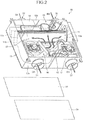
- FIG. 2 is a perspective view illustrating the inside of the heat exchange ventilation apparatus in the embodiment
- FIG. 3 is a perspective view illustrating the inside of the heat exchange ventilation apparatus in the embodiment in a direction different from that of FIG. 2 .
- a heat exchange ventilation apparatus 90 in the embodiment is provided with a heat exchanger 11, which performs heat exchange between outdoor air and indoor air, in a casing 13 formed into a rectangular parallelepiped box shape and performs ventilation inside a room while performing heat exchange by supplying air and exhausting air simultaneously.
- a supply air filter 12a is arranged, and, at the inlet of the exhaust-air heat exchange passage 11b, an exhaust air filter 12b is arranged.
- the heat exchanger 11, an indoor-side partition member 14, an outdoor-side partition member 15, the supply air blower 16, and the exhaust air blower 17 are arranged in the casing 13, so that the supply air passage 22 and the exhaust air passage 26 are formed.
- the supply air blower 16 is arranged in the left corner on the outdoor side of the casing 13 and the exhaust air blower 17 is arranged in the right corner on the outdoor side.
- the outdoor side (the blowers arranged side) of the casing 13 is covered by a top plate 33 and the indoor side (the heat exchanger 11 arranged side) is covered by a maintenance panel 31.
- the heat exchanger 11 formed into a quadrangular prism shape is arranged across substantially the entire width of the casing 13 in parallel with an indoor-side side plate 13b on a side closer to the indoor-side side plate 13b in the casing 13, a square lower-side corner portion of the heat exchanger 11 is brought into contact with the bottom plate of the casing 13, and an upper-side corner portion opposing the lower-side corner portion is brought into contact with the maintenance panel 31 that covers the indoor side of the casing 13. Moreover, an indoor-side corner portion of the heat exchanger 11 is brought into contact with the indoor-side partition member 14 and an outdoor-side corner portion is brought into contact with a leading edge portion 15a (see FIG. 5-1 ) of the outdoor-side partition member 15.
- the supply air passage 22 is formed as an air passage that passes through, in turn, the outdoor-side inlet 21 provided in an outdoor-side side plate 13a of the casing 13, the inside of the supply air blower 16, the upper side of the outdoor-side partition member 15, the supply air filter 12a, the supply-air heat exchange passage 11a, the lower side of the indoor-side partition member 14, and the indoor-side outlet 23 provided in the indoor-side side plate 13b.
- the exhaust air passage 26 is formed as an air passage that passes through, in turn, the indoor-side inlet 25 provided in the indoor-side side plate 13b of the casing 13, the side of the indoor-side partition member 14, the exhaust air filter 12b, the exhaust-air heat exchange passage 11b, the lower side of the outdoor-side partition member 15, the inside of the exhaust air blower 17, and the outdoor-side outlet 27 provided in the outdoor-side side plate 13a of the casing 13.
- FIG. 4 is an exploded perspective view of the supply air blower and the outdoor-side partition member of the heat exchange ventilation apparatus in the embodiment
- FIG. 5-1 is a perspective view of the outdoor-side partition member in the embodiment
- FIG. 5-2 is a perspective view of the outdoor-side partition member in the embodiment in a direction different from that of FIG. 5-1 .
- a suction chamber 15b which is arranged in the left corner on the outdoor side of the casing 13, accommodates the supply air blower 16, and supplies outside air suctioned from the outdoor-side inlet 21 to the supply air blower 16, a blowing chamber 15c, which supplies outside air blown out from the supply air blower 16 to the heat exchanger 11, and a chamber outlet 15d, which communicates between the outlet of the supply air blower 16 and the blowing chamber 15c, are formed.
- the blowing chamber 15c is arranged in the middle of a casing 13 between the supply air blower 16 and the exhaust air blower 17, is closed on the outdoor side (back portion), and has an outlet portion 15i that widens in a bell-mouth shape toward the heat exchanger 11.
- the chamber outlet 15d is provided in one side portion of the closed back portion of the blowing chamber 15c and the other side portion (wall portion) of the back portion becomes a concave curved surface 15e.
- An one side portion (wall portion) 15f on the outlet portion 15i side of the blowing chamber 15c widens toward the left side in FIG.
- the other side portion becomes a convex curved portion 15g that is smoothly continuous with the concave curved surface 15e of the back portion and widens largely toward the right side in FIG. 5-1 .
- the back portion of the blowing chamber 15c becomes an accumulation portion 15h of blown out air.
- FIG. 6 is a perspective view illustrating a modified example of the outdoor-side partition member in the embodiment.
- the outdoor-side partition member 15 in the modified example two fin-shaped straightening plates 15s that straightens the airflow are provided at the outlet portion 15i of the blowing chamber 15c. With the straightening plates 15s, the air speed distribution at the inlet portion of the heat exchanger 11 can be further uniformed.
- the straightening plates 15s are directed perpendicular to the airflow direction to be baffles, the air speed distribution at the inlet portion of the heat exchanger 11 can be uniformed.
- a punching metal or a filter can be arranged at the outlet portion 15i of the blowing chamber 15c.
- a plurality of kinds among the straightening plate 15s, the baffle, the punching metal, and the filter can be arranged.
- the supply air blower 16 and the supply air passage 22, and the exhaust air blower 17 and the exhaust air passage 26 can be interchanged.
- the heat exchange ventilation apparatus according to the present invention is useful as an apparatus with high heat exchange efficiency and low noise.
Landscapes
- Engineering & Computer Science (AREA)
- Chemical & Material Sciences (AREA)
- Combustion & Propulsion (AREA)
- Mechanical Engineering (AREA)
- General Engineering & Computer Science (AREA)
- Heat-Exchange Devices With Radiators And Conduit Assemblies (AREA)
- Other Air-Conditioning Systems (AREA)
- Central Air Conditioning (AREA)
Applications Claiming Priority (1)
| Application Number | Priority Date | Filing Date | Title |
|---|---|---|---|
| PCT/JP2009/056346 WO2010109662A1 (ja) | 2009-03-27 | 2009-03-27 | 熱交換換気装置 |
Publications (3)
| Publication Number | Publication Date |
|---|---|
| EP2413052A1 EP2413052A1 (en) | 2012-02-01 |
| EP2413052A4 EP2413052A4 (en) | 2014-01-08 |
| EP2413052B1 true EP2413052B1 (en) | 2018-12-19 |
Family
ID=42780371
Family Applications (1)
| Application Number | Title | Priority Date | Filing Date |
|---|---|---|---|
| EP09842276.9A Active EP2413052B1 (en) | 2009-03-27 | 2009-03-27 | Heat exchange ventilation device |
Country Status (4)
Families Citing this family (4)
| Publication number | Priority date | Publication date | Assignee | Title |
|---|---|---|---|---|
| CN105333601B (zh) * | 2014-06-24 | 2018-06-12 | 海信(山东)空调有限公司 | 一种全热交换器 |
| JP6755816B2 (ja) | 2017-02-14 | 2020-09-16 | 伸和コントロールズ株式会社 | 空気調和装置 |
| KR20190017506A (ko) * | 2017-08-11 | 2019-02-20 | 엘지전자 주식회사 | 공기조화장치 |
| WO2025186852A1 (en) * | 2024-03-07 | 2025-09-12 | Vortice S.P.A. | Ventilation appliance |
Family Cites Families (2)
| Publication number | Priority date | Publication date | Assignee | Title |
|---|---|---|---|---|
| JPH03251634A (ja) * | 1990-03-01 | 1991-11-11 | Matsushita Electric Ind Co Ltd | 熱交換気装置 |
| JP4863696B2 (ja) * | 2005-11-07 | 2012-01-25 | 協立エアテック株式会社 | 換気装置 |
-
2009
- 2009-03-27 JP JP2011505781A patent/JP5174951B2/ja active Active
- 2009-03-27 EP EP09842276.9A patent/EP2413052B1/en active Active
- 2009-03-27 WO PCT/JP2009/056346 patent/WO2010109662A1/ja active Application Filing
- 2009-07-01 TW TW098122208A patent/TW201035503A/zh not_active IP Right Cessation
Non-Patent Citations (1)
| Title |
|---|
| None * |
Also Published As
| Publication number | Publication date |
|---|---|
| EP2413052A4 (en) | 2014-01-08 |
| JP5174951B2 (ja) | 2013-04-03 |
| JPWO2010109662A1 (ja) | 2012-09-27 |
| EP2413052A1 (en) | 2012-02-01 |
| TWI373598B (GUID-C5D7CC26-194C-43D0-91A1-9AE8C70A9BFF.html) | 2012-10-01 |
| TW201035503A (en) | 2010-10-01 |
| WO2010109662A1 (ja) | 2010-09-30 |
Similar Documents
| Publication | Publication Date | Title |
|---|---|---|
| EP1939571A2 (en) | Heat exchange element for ventilating apparatus | |
| EP2413052B1 (en) | Heat exchange ventilation device | |
| JP2015180847A (ja) | 空気調和機の室内機 | |
| EP1939574A1 (en) | Ventilating apparatus, heat exchange apparatus, heat exchange element, and rib therefor | |
| JP3847567B2 (ja) | 空気調和機の室外ユニット | |
| JP6041844B2 (ja) | 空調システム | |
| EP2413051B1 (en) | Heat exchange and ventilation device | |
| KR20080073488A (ko) | 환기장치 | |
| JP5108241B2 (ja) | 風向ガイドユニット | |
| JP2014092333A (ja) | 熱交換換気装置 | |
| JP2012072937A (ja) | 空気調和装置 | |
| JP5269156B2 (ja) | 風向ガイドユニット、および、空気調和装置の室外ユニット | |
| JP2015175557A (ja) | ダクト型空気調和機 | |
| JP2018054191A (ja) | 熱交換機器 | |
| WO2021124446A1 (ja) | 空気調和装置の室内機 | |
| JP2008116170A (ja) | 熱交換換気装置 | |
| CN206247485U (zh) | 风管式空调室内机 | |
| JP5693329B2 (ja) | 排気装置 | |
| US20240328645A1 (en) | Ceiling element with air outlet box | |
| WO2009130897A1 (ja) | 熱交換機器用風路構成板およびそれを用いた熱交換機器 | |
| JP2008064419A (ja) | 換気装置 | |
| US20250020363A1 (en) | Sound-reducing exhaust air system | |
| JP5710342B2 (ja) | 排気装置 | |
| JP2003004258A (ja) | 空気調和機の室外機 | |
| JPH08178333A (ja) | 空気調和機 |
Legal Events
| Date | Code | Title | Description |
|---|---|---|---|
| PUAI | Public reference made under article 153(3) epc to a published international application that has entered the european phase |
Free format text: ORIGINAL CODE: 0009012 |
|
| 17P | Request for examination filed |
Effective date: 20110704 |
|
| AK | Designated contracting states |
Kind code of ref document: A1 Designated state(s): AT BE BG CH CY CZ DE DK EE ES FI FR GB GR HR HU IE IS IT LI LT LU LV MC MK MT NL NO PL PT RO SE SI SK TR |
|
| DAX | Request for extension of the european patent (deleted) | ||
| A4 | Supplementary search report drawn up and despatched |
Effective date: 20131209 |
|
| RIC1 | Information provided on ipc code assigned before grant |
Ipc: F24F 13/08 20060101ALI20131203BHEP Ipc: F24F 13/20 20060101ALI20131203BHEP Ipc: F24F 12/00 20060101ALI20131203BHEP Ipc: F24F 7/08 20060101AFI20131203BHEP |
|
| GRAP | Despatch of communication of intention to grant a patent |
Free format text: ORIGINAL CODE: EPIDOSNIGR1 |
|
| STAA | Information on the status of an ep patent application or granted ep patent |
Free format text: STATUS: GRANT OF PATENT IS INTENDED |
|
| RIC1 | Information provided on ipc code assigned before grant |
Ipc: F24F 13/20 20060101ALI20180712BHEP Ipc: F24F 7/08 20060101AFI20180712BHEP Ipc: F24F 12/00 20060101ALI20180712BHEP Ipc: F24F 13/08 20060101ALI20180712BHEP |
|
| INTG | Intention to grant announced |
Effective date: 20180726 |
|
| GRAS | Grant fee paid |
Free format text: ORIGINAL CODE: EPIDOSNIGR3 |
|
| GRAA | (expected) grant |
Free format text: ORIGINAL CODE: 0009210 |
|
| STAA | Information on the status of an ep patent application or granted ep patent |
Free format text: STATUS: THE PATENT HAS BEEN GRANTED |
|
| AK | Designated contracting states |
Kind code of ref document: B1 Designated state(s): AT BE BG CH CY CZ DE DK EE ES FI FR GB GR HR HU IE IS IT LI LT LU LV MC MK MT NL NO PL PT RO SE SI SK TR |
|
| REG | Reference to a national code |
Ref country code: GB Ref legal event code: FG4D |
|
| REG | Reference to a national code |
Ref country code: CH Ref legal event code: EP |
|
| REG | Reference to a national code |
Ref country code: DE Ref legal event code: R096 Ref document number: 602009056333 Country of ref document: DE |
|
| REG | Reference to a national code |
Ref country code: IE Ref legal event code: FG4D |
|
| REG | Reference to a national code |
Ref country code: AT Ref legal event code: REF Ref document number: 1079155 Country of ref document: AT Kind code of ref document: T Effective date: 20190115 |
|
| REG | Reference to a national code |
Ref country code: NL Ref legal event code: MP Effective date: 20181219 |
|
| PG25 | Lapsed in a contracting state [announced via postgrant information from national office to epo] |
Ref country code: HR Free format text: LAPSE BECAUSE OF FAILURE TO SUBMIT A TRANSLATION OF THE DESCRIPTION OR TO PAY THE FEE WITHIN THE PRESCRIBED TIME-LIMIT Effective date: 20181219 Ref country code: LT Free format text: LAPSE BECAUSE OF FAILURE TO SUBMIT A TRANSLATION OF THE DESCRIPTION OR TO PAY THE FEE WITHIN THE PRESCRIBED TIME-LIMIT Effective date: 20181219 Ref country code: LV Free format text: LAPSE BECAUSE OF FAILURE TO SUBMIT A TRANSLATION OF THE DESCRIPTION OR TO PAY THE FEE WITHIN THE PRESCRIBED TIME-LIMIT Effective date: 20181219 Ref country code: NO Free format text: LAPSE BECAUSE OF FAILURE TO SUBMIT A TRANSLATION OF THE DESCRIPTION OR TO PAY THE FEE WITHIN THE PRESCRIBED TIME-LIMIT Effective date: 20190319 Ref country code: FI Free format text: LAPSE BECAUSE OF FAILURE TO SUBMIT A TRANSLATION OF THE DESCRIPTION OR TO PAY THE FEE WITHIN THE PRESCRIBED TIME-LIMIT Effective date: 20181219 Ref country code: BG Free format text: LAPSE BECAUSE OF FAILURE TO SUBMIT A TRANSLATION OF THE DESCRIPTION OR TO PAY THE FEE WITHIN THE PRESCRIBED TIME-LIMIT Effective date: 20190319 |
|
| REG | Reference to a national code |
Ref country code: LT Ref legal event code: MG4D |
|
| REG | Reference to a national code |
Ref country code: AT Ref legal event code: MK05 Ref document number: 1079155 Country of ref document: AT Kind code of ref document: T Effective date: 20181219 |
|
| PG25 | Lapsed in a contracting state [announced via postgrant information from national office to epo] |
Ref country code: GR Free format text: LAPSE BECAUSE OF FAILURE TO SUBMIT A TRANSLATION OF THE DESCRIPTION OR TO PAY THE FEE WITHIN THE PRESCRIBED TIME-LIMIT Effective date: 20190320 Ref country code: SE Free format text: LAPSE BECAUSE OF FAILURE TO SUBMIT A TRANSLATION OF THE DESCRIPTION OR TO PAY THE FEE WITHIN THE PRESCRIBED TIME-LIMIT Effective date: 20181219 |
|
| PG25 | Lapsed in a contracting state [announced via postgrant information from national office to epo] |
Ref country code: NL Free format text: LAPSE BECAUSE OF FAILURE TO SUBMIT A TRANSLATION OF THE DESCRIPTION OR TO PAY THE FEE WITHIN THE PRESCRIBED TIME-LIMIT Effective date: 20181219 |
|
| PG25 | Lapsed in a contracting state [announced via postgrant information from national office to epo] |
Ref country code: CZ Free format text: LAPSE BECAUSE OF FAILURE TO SUBMIT A TRANSLATION OF THE DESCRIPTION OR TO PAY THE FEE WITHIN THE PRESCRIBED TIME-LIMIT Effective date: 20181219 Ref country code: ES Free format text: LAPSE BECAUSE OF FAILURE TO SUBMIT A TRANSLATION OF THE DESCRIPTION OR TO PAY THE FEE WITHIN THE PRESCRIBED TIME-LIMIT Effective date: 20181219 Ref country code: PL Free format text: LAPSE BECAUSE OF FAILURE TO SUBMIT A TRANSLATION OF THE DESCRIPTION OR TO PAY THE FEE WITHIN THE PRESCRIBED TIME-LIMIT Effective date: 20181219 Ref country code: PT Free format text: LAPSE BECAUSE OF FAILURE TO SUBMIT A TRANSLATION OF THE DESCRIPTION OR TO PAY THE FEE WITHIN THE PRESCRIBED TIME-LIMIT Effective date: 20190419 Ref country code: IT Free format text: LAPSE BECAUSE OF FAILURE TO SUBMIT A TRANSLATION OF THE DESCRIPTION OR TO PAY THE FEE WITHIN THE PRESCRIBED TIME-LIMIT Effective date: 20181219 |
|
| PG25 | Lapsed in a contracting state [announced via postgrant information from national office to epo] |
Ref country code: EE Free format text: LAPSE BECAUSE OF FAILURE TO SUBMIT A TRANSLATION OF THE DESCRIPTION OR TO PAY THE FEE WITHIN THE PRESCRIBED TIME-LIMIT Effective date: 20181219 Ref country code: SK Free format text: LAPSE BECAUSE OF FAILURE TO SUBMIT A TRANSLATION OF THE DESCRIPTION OR TO PAY THE FEE WITHIN THE PRESCRIBED TIME-LIMIT Effective date: 20181219 Ref country code: RO Free format text: LAPSE BECAUSE OF FAILURE TO SUBMIT A TRANSLATION OF THE DESCRIPTION OR TO PAY THE FEE WITHIN THE PRESCRIBED TIME-LIMIT Effective date: 20181219 Ref country code: IS Free format text: LAPSE BECAUSE OF FAILURE TO SUBMIT A TRANSLATION OF THE DESCRIPTION OR TO PAY THE FEE WITHIN THE PRESCRIBED TIME-LIMIT Effective date: 20190419 |
|
| REG | Reference to a national code |
Ref country code: DE Ref legal event code: R097 Ref document number: 602009056333 Country of ref document: DE |
|
| REG | Reference to a national code |
Ref country code: DE Ref legal event code: R119 Ref document number: 602009056333 Country of ref document: DE |
|
| PLBE | No opposition filed within time limit |
Free format text: ORIGINAL CODE: 0009261 |
|
| STAA | Information on the status of an ep patent application or granted ep patent |
Free format text: STATUS: NO OPPOSITION FILED WITHIN TIME LIMIT |
|
| PG25 | Lapsed in a contracting state [announced via postgrant information from national office to epo] |
Ref country code: DK Free format text: LAPSE BECAUSE OF FAILURE TO SUBMIT A TRANSLATION OF THE DESCRIPTION OR TO PAY THE FEE WITHIN THE PRESCRIBED TIME-LIMIT Effective date: 20181219 Ref country code: AT Free format text: LAPSE BECAUSE OF FAILURE TO SUBMIT A TRANSLATION OF THE DESCRIPTION OR TO PAY THE FEE WITHIN THE PRESCRIBED TIME-LIMIT Effective date: 20181219 Ref country code: MC Free format text: LAPSE BECAUSE OF FAILURE TO SUBMIT A TRANSLATION OF THE DESCRIPTION OR TO PAY THE FEE WITHIN THE PRESCRIBED TIME-LIMIT Effective date: 20181219 |
|
| REG | Reference to a national code |
Ref country code: CH Ref legal event code: PL |
|
| 26N | No opposition filed |
Effective date: 20190920 |
|
| PG25 | Lapsed in a contracting state [announced via postgrant information from national office to epo] |
Ref country code: LU Free format text: LAPSE BECAUSE OF NON-PAYMENT OF DUE FEES Effective date: 20190327 |
|
| REG | Reference to a national code |
Ref country code: BE Ref legal event code: MM Effective date: 20190331 |
|
| PG25 | Lapsed in a contracting state [announced via postgrant information from national office to epo] |
Ref country code: LI Free format text: LAPSE BECAUSE OF NON-PAYMENT OF DUE FEES Effective date: 20190331 Ref country code: DE Free format text: LAPSE BECAUSE OF NON-PAYMENT OF DUE FEES Effective date: 20191001 Ref country code: IE Free format text: LAPSE BECAUSE OF NON-PAYMENT OF DUE FEES Effective date: 20190327 Ref country code: CH Free format text: LAPSE BECAUSE OF NON-PAYMENT OF DUE FEES Effective date: 20190331 |
|
| PG25 | Lapsed in a contracting state [announced via postgrant information from national office to epo] |
Ref country code: BE Free format text: LAPSE BECAUSE OF NON-PAYMENT OF DUE FEES Effective date: 20190331 Ref country code: FR Free format text: LAPSE BECAUSE OF NON-PAYMENT OF DUE FEES Effective date: 20190331 Ref country code: SI Free format text: LAPSE BECAUSE OF FAILURE TO SUBMIT A TRANSLATION OF THE DESCRIPTION OR TO PAY THE FEE WITHIN THE PRESCRIBED TIME-LIMIT Effective date: 20181219 |
|
| PG25 | Lapsed in a contracting state [announced via postgrant information from national office to epo] |
Ref country code: TR Free format text: LAPSE BECAUSE OF FAILURE TO SUBMIT A TRANSLATION OF THE DESCRIPTION OR TO PAY THE FEE WITHIN THE PRESCRIBED TIME-LIMIT Effective date: 20181219 |
|
| PG25 | Lapsed in a contracting state [announced via postgrant information from national office to epo] |
Ref country code: MT Free format text: LAPSE BECAUSE OF NON-PAYMENT OF DUE FEES Effective date: 20190327 |
|
| PG25 | Lapsed in a contracting state [announced via postgrant information from national office to epo] |
Ref country code: CY Free format text: LAPSE BECAUSE OF FAILURE TO SUBMIT A TRANSLATION OF THE DESCRIPTION OR TO PAY THE FEE WITHIN THE PRESCRIBED TIME-LIMIT Effective date: 20181219 |
|
| PG25 | Lapsed in a contracting state [announced via postgrant information from national office to epo] |
Ref country code: HU Free format text: LAPSE BECAUSE OF FAILURE TO SUBMIT A TRANSLATION OF THE DESCRIPTION OR TO PAY THE FEE WITHIN THE PRESCRIBED TIME-LIMIT; INVALID AB INITIO Effective date: 20090327 |
|
| REG | Reference to a national code |
Ref country code: GB Ref legal event code: 746 Effective date: 20220510 |
|
| PG25 | Lapsed in a contracting state [announced via postgrant information from national office to epo] |
Ref country code: MK Free format text: LAPSE BECAUSE OF FAILURE TO SUBMIT A TRANSLATION OF THE DESCRIPTION OR TO PAY THE FEE WITHIN THE PRESCRIBED TIME-LIMIT Effective date: 20181219 |
|
| PGFP | Annual fee paid to national office [announced via postgrant information from national office to epo] |
Ref country code: GB Payment date: 20240201 Year of fee payment: 16 |