EP2411240B1 - Systeme d'entrainement electrique, son procédé de fonctionnement - Google Patents
Systeme d'entrainement electrique, son procédé de fonctionnement Download PDFInfo
- Publication number
- EP2411240B1 EP2411240B1 EP10709696.8A EP10709696A EP2411240B1 EP 2411240 B1 EP2411240 B1 EP 2411240B1 EP 10709696 A EP10709696 A EP 10709696A EP 2411240 B1 EP2411240 B1 EP 2411240B1
- Authority
- EP
- European Patent Office
- Prior art keywords
- energy store
- inverter
- voltage
- current
- rectifier
- Prior art date
- Legal status (The legal status is an assumption and is not a legal conclusion. Google has not performed a legal analysis and makes no representation as to the accuracy of the status listed.)
- Active
Links
- 238000000034 method Methods 0.000 title claims description 12
- 238000004804 winding Methods 0.000 claims description 69
- 239000004065 semiconductor Substances 0.000 claims description 9
- 239000003990 capacitor Substances 0.000 claims description 8
- 238000004146 energy storage Methods 0.000 description 7
- 230000001360 synchronised effect Effects 0.000 description 4
- 230000008878 coupling Effects 0.000 description 3
- 238000010168 coupling process Methods 0.000 description 3
- 238000005859 coupling reaction Methods 0.000 description 3
- 238000009499 grossing Methods 0.000 description 3
- 230000001939 inductive effect Effects 0.000 description 3
- 230000007935 neutral effect Effects 0.000 description 2
- 206010063493 Premature ageing Diseases 0.000 description 1
- 208000032038 Premature aging Diseases 0.000 description 1
- 230000005540 biological transmission Effects 0.000 description 1
- 230000001419 dependent effect Effects 0.000 description 1
- 230000006866 deterioration Effects 0.000 description 1
- 238000010586 diagram Methods 0.000 description 1
- 230000000694 effects Effects 0.000 description 1
- 238000013021 overheating Methods 0.000 description 1
- 230000001105 regulatory effect Effects 0.000 description 1
Images
Classifications
-
- H—ELECTRICITY
- H02—GENERATION; CONVERSION OR DISTRIBUTION OF ELECTRIC POWER
- H02J—CIRCUIT ARRANGEMENTS OR SYSTEMS FOR SUPPLYING OR DISTRIBUTING ELECTRIC POWER; SYSTEMS FOR STORING ELECTRIC ENERGY
- H02J7/00—Circuit arrangements for charging or depolarising batteries or for supplying loads from batteries
- H02J7/02—Circuit arrangements for charging or depolarising batteries or for supplying loads from batteries for charging batteries from ac mains by converters
-
- B—PERFORMING OPERATIONS; TRANSPORTING
- B60—VEHICLES IN GENERAL
- B60L—PROPULSION OF ELECTRICALLY-PROPELLED VEHICLES; SUPPLYING ELECTRIC POWER FOR AUXILIARY EQUIPMENT OF ELECTRICALLY-PROPELLED VEHICLES; ELECTRODYNAMIC BRAKE SYSTEMS FOR VEHICLES IN GENERAL; MAGNETIC SUSPENSION OR LEVITATION FOR VEHICLES; MONITORING OPERATING VARIABLES OF ELECTRICALLY-PROPELLED VEHICLES; ELECTRIC SAFETY DEVICES FOR ELECTRICALLY-PROPELLED VEHICLES
- B60L15/00—Methods, circuits, or devices for controlling the traction-motor speed of electrically-propelled vehicles
- B60L15/007—Physical arrangements or structures of drive train converters specially adapted for the propulsion motors of electric vehicles
-
- B—PERFORMING OPERATIONS; TRANSPORTING
- B60—VEHICLES IN GENERAL
- B60L—PROPULSION OF ELECTRICALLY-PROPELLED VEHICLES; SUPPLYING ELECTRIC POWER FOR AUXILIARY EQUIPMENT OF ELECTRICALLY-PROPELLED VEHICLES; ELECTRODYNAMIC BRAKE SYSTEMS FOR VEHICLES IN GENERAL; MAGNETIC SUSPENSION OR LEVITATION FOR VEHICLES; MONITORING OPERATING VARIABLES OF ELECTRICALLY-PROPELLED VEHICLES; ELECTRIC SAFETY DEVICES FOR ELECTRICALLY-PROPELLED VEHICLES
- B60L50/00—Electric propulsion with power supplied within the vehicle
- B60L50/50—Electric propulsion with power supplied within the vehicle using propulsion power supplied by batteries or fuel cells
- B60L50/51—Electric propulsion with power supplied within the vehicle using propulsion power supplied by batteries or fuel cells characterised by AC-motors
-
- B—PERFORMING OPERATIONS; TRANSPORTING
- B60—VEHICLES IN GENERAL
- B60L—PROPULSION OF ELECTRICALLY-PROPELLED VEHICLES; SUPPLYING ELECTRIC POWER FOR AUXILIARY EQUIPMENT OF ELECTRICALLY-PROPELLED VEHICLES; ELECTRODYNAMIC BRAKE SYSTEMS FOR VEHICLES IN GENERAL; MAGNETIC SUSPENSION OR LEVITATION FOR VEHICLES; MONITORING OPERATING VARIABLES OF ELECTRICALLY-PROPELLED VEHICLES; ELECTRIC SAFETY DEVICES FOR ELECTRICALLY-PROPELLED VEHICLES
- B60L53/00—Methods of charging batteries, specially adapted for electric vehicles; Charging stations or on-board charging equipment therefor; Exchange of energy storage elements in electric vehicles
- B60L53/10—Methods of charging batteries, specially adapted for electric vehicles; Charging stations or on-board charging equipment therefor; Exchange of energy storage elements in electric vehicles characterised by the energy transfer between the charging station and the vehicle
- B60L53/12—Inductive energy transfer
- B60L53/122—Circuits or methods for driving the primary coil, e.g. supplying electric power to the coil
-
- B—PERFORMING OPERATIONS; TRANSPORTING
- B60—VEHICLES IN GENERAL
- B60L—PROPULSION OF ELECTRICALLY-PROPELLED VEHICLES; SUPPLYING ELECTRIC POWER FOR AUXILIARY EQUIPMENT OF ELECTRICALLY-PROPELLED VEHICLES; ELECTRODYNAMIC BRAKE SYSTEMS FOR VEHICLES IN GENERAL; MAGNETIC SUSPENSION OR LEVITATION FOR VEHICLES; MONITORING OPERATING VARIABLES OF ELECTRICALLY-PROPELLED VEHICLES; ELECTRIC SAFETY DEVICES FOR ELECTRICALLY-PROPELLED VEHICLES
- B60L53/00—Methods of charging batteries, specially adapted for electric vehicles; Charging stations or on-board charging equipment therefor; Exchange of energy storage elements in electric vehicles
- B60L53/20—Methods of charging batteries, specially adapted for electric vehicles; Charging stations or on-board charging equipment therefor; Exchange of energy storage elements in electric vehicles characterised by converters located in the vehicle
- B60L53/22—Constructional details or arrangements of charging converters specially adapted for charging electric vehicles
-
- B—PERFORMING OPERATIONS; TRANSPORTING
- B60—VEHICLES IN GENERAL
- B60L—PROPULSION OF ELECTRICALLY-PROPELLED VEHICLES; SUPPLYING ELECTRIC POWER FOR AUXILIARY EQUIPMENT OF ELECTRICALLY-PROPELLED VEHICLES; ELECTRODYNAMIC BRAKE SYSTEMS FOR VEHICLES IN GENERAL; MAGNETIC SUSPENSION OR LEVITATION FOR VEHICLES; MONITORING OPERATING VARIABLES OF ELECTRICALLY-PROPELLED VEHICLES; ELECTRIC SAFETY DEVICES FOR ELECTRICALLY-PROPELLED VEHICLES
- B60L53/00—Methods of charging batteries, specially adapted for electric vehicles; Charging stations or on-board charging equipment therefor; Exchange of energy storage elements in electric vehicles
- B60L53/20—Methods of charging batteries, specially adapted for electric vehicles; Charging stations or on-board charging equipment therefor; Exchange of energy storage elements in electric vehicles characterised by converters located in the vehicle
- B60L53/24—Using the vehicle's propulsion converter for charging
-
- H—ELECTRICITY
- H02—GENERATION; CONVERSION OR DISTRIBUTION OF ELECTRIC POWER
- H02J—CIRCUIT ARRANGEMENTS OR SYSTEMS FOR SUPPLYING OR DISTRIBUTING ELECTRIC POWER; SYSTEMS FOR STORING ELECTRIC ENERGY
- H02J50/00—Circuit arrangements or systems for wireless supply or distribution of electric power
- H02J50/10—Circuit arrangements or systems for wireless supply or distribution of electric power using inductive coupling
- H02J50/12—Circuit arrangements or systems for wireless supply or distribution of electric power using inductive coupling of the resonant type
-
- B—PERFORMING OPERATIONS; TRANSPORTING
- B60—VEHICLES IN GENERAL
- B60L—PROPULSION OF ELECTRICALLY-PROPELLED VEHICLES; SUPPLYING ELECTRIC POWER FOR AUXILIARY EQUIPMENT OF ELECTRICALLY-PROPELLED VEHICLES; ELECTRODYNAMIC BRAKE SYSTEMS FOR VEHICLES IN GENERAL; MAGNETIC SUSPENSION OR LEVITATION FOR VEHICLES; MONITORING OPERATING VARIABLES OF ELECTRICALLY-PROPELLED VEHICLES; ELECTRIC SAFETY DEVICES FOR ELECTRICALLY-PROPELLED VEHICLES
- B60L2220/00—Electrical machine types; Structures or applications thereof
- B60L2220/50—Structural details of electrical machines
- B60L2220/54—Windings for different functions
-
- H—ELECTRICITY
- H02—GENERATION; CONVERSION OR DISTRIBUTION OF ELECTRIC POWER
- H02J—CIRCUIT ARRANGEMENTS OR SYSTEMS FOR SUPPLYING OR DISTRIBUTING ELECTRIC POWER; SYSTEMS FOR STORING ELECTRIC ENERGY
- H02J2207/00—Indexing scheme relating to details of circuit arrangements for charging or depolarising batteries or for supplying loads from batteries
- H02J2207/20—Charging or discharging characterised by the power electronics converter
-
- H—ELECTRICITY
- H02—GENERATION; CONVERSION OR DISTRIBUTION OF ELECTRIC POWER
- H02P—CONTROL OR REGULATION OF ELECTRIC MOTORS, ELECTRIC GENERATORS OR DYNAMO-ELECTRIC CONVERTERS; CONTROLLING TRANSFORMERS, REACTORS OR CHOKE COILS
- H02P2209/00—Indexing scheme relating to controlling arrangements characterised by the waveform of the supplied voltage or current
- H02P2209/01—Motors with neutral point connected to the power supply
-
- Y—GENERAL TAGGING OF NEW TECHNOLOGICAL DEVELOPMENTS; GENERAL TAGGING OF CROSS-SECTIONAL TECHNOLOGIES SPANNING OVER SEVERAL SECTIONS OF THE IPC; TECHNICAL SUBJECTS COVERED BY FORMER USPC CROSS-REFERENCE ART COLLECTIONS [XRACs] AND DIGESTS
- Y02—TECHNOLOGIES OR APPLICATIONS FOR MITIGATION OR ADAPTATION AGAINST CLIMATE CHANGE
- Y02T—CLIMATE CHANGE MITIGATION TECHNOLOGIES RELATED TO TRANSPORTATION
- Y02T10/00—Road transport of goods or passengers
- Y02T10/60—Other road transportation technologies with climate change mitigation effect
- Y02T10/64—Electric machine technologies in electromobility
-
- Y—GENERAL TAGGING OF NEW TECHNOLOGICAL DEVELOPMENTS; GENERAL TAGGING OF CROSS-SECTIONAL TECHNOLOGIES SPANNING OVER SEVERAL SECTIONS OF THE IPC; TECHNICAL SUBJECTS COVERED BY FORMER USPC CROSS-REFERENCE ART COLLECTIONS [XRACs] AND DIGESTS
- Y02—TECHNOLOGIES OR APPLICATIONS FOR MITIGATION OR ADAPTATION AGAINST CLIMATE CHANGE
- Y02T—CLIMATE CHANGE MITIGATION TECHNOLOGIES RELATED TO TRANSPORTATION
- Y02T10/00—Road transport of goods or passengers
- Y02T10/60—Other road transportation technologies with climate change mitigation effect
- Y02T10/70—Energy storage systems for electromobility, e.g. batteries
-
- Y—GENERAL TAGGING OF NEW TECHNOLOGICAL DEVELOPMENTS; GENERAL TAGGING OF CROSS-SECTIONAL TECHNOLOGIES SPANNING OVER SEVERAL SECTIONS OF THE IPC; TECHNICAL SUBJECTS COVERED BY FORMER USPC CROSS-REFERENCE ART COLLECTIONS [XRACs] AND DIGESTS
- Y02—TECHNOLOGIES OR APPLICATIONS FOR MITIGATION OR ADAPTATION AGAINST CLIMATE CHANGE
- Y02T—CLIMATE CHANGE MITIGATION TECHNOLOGIES RELATED TO TRANSPORTATION
- Y02T10/00—Road transport of goods or passengers
- Y02T10/60—Other road transportation technologies with climate change mitigation effect
- Y02T10/7072—Electromobility specific charging systems or methods for batteries, ultracapacitors, supercapacitors or double-layer capacitors
-
- Y—GENERAL TAGGING OF NEW TECHNOLOGICAL DEVELOPMENTS; GENERAL TAGGING OF CROSS-SECTIONAL TECHNOLOGIES SPANNING OVER SEVERAL SECTIONS OF THE IPC; TECHNICAL SUBJECTS COVERED BY FORMER USPC CROSS-REFERENCE ART COLLECTIONS [XRACs] AND DIGESTS
- Y02—TECHNOLOGIES OR APPLICATIONS FOR MITIGATION OR ADAPTATION AGAINST CLIMATE CHANGE
- Y02T—CLIMATE CHANGE MITIGATION TECHNOLOGIES RELATED TO TRANSPORTATION
- Y02T90/00—Enabling technologies or technologies with a potential or indirect contribution to GHG emissions mitigation
- Y02T90/10—Technologies relating to charging of electric vehicles
- Y02T90/12—Electric charging stations
-
- Y—GENERAL TAGGING OF NEW TECHNOLOGICAL DEVELOPMENTS; GENERAL TAGGING OF CROSS-SECTIONAL TECHNOLOGIES SPANNING OVER SEVERAL SECTIONS OF THE IPC; TECHNICAL SUBJECTS COVERED BY FORMER USPC CROSS-REFERENCE ART COLLECTIONS [XRACs] AND DIGESTS
- Y02—TECHNOLOGIES OR APPLICATIONS FOR MITIGATION OR ADAPTATION AGAINST CLIMATE CHANGE
- Y02T—CLIMATE CHANGE MITIGATION TECHNOLOGIES RELATED TO TRANSPORTATION
- Y02T90/00—Enabling technologies or technologies with a potential or indirect contribution to GHG emissions mitigation
- Y02T90/10—Technologies relating to charging of electric vehicles
- Y02T90/14—Plug-in electric vehicles
Definitions
- the invention relates to a drive system, a method for operating a drive system and a use.
- the invention is therefore based on the object of providing an inexpensive charging circuit for an energy store.
- the object is achieved in the drive system according to the features in claim 1 and in the method for operating a drive system in accordance with the features specified in claim 6.
- the drive system comprises an electric motor, an inverter and at least one energy store, wherein the electric motor can be fed by the inverter, which can be supplied from the energy store, wherein the electric motor is designed as a three-phase motor in star connection, wherein the star point of the electric motor can be supplied with current from a rectifier, which is fed by a secondary winding, wherein the secondary winding can be supplied from a primary winding, which is provided inductively coupled to the secondary winding.
- the advantage here is that a very compact charging circuit can be implemented, and even at the secondary winding there may be a much lower voltage level than the voltage required to charge the energy store. Because the stator winding is connected to the energy store via the inverter and can thus be used as an inductor for the charging circuit, for example in the manner of a buck converter, it is even possible to raise the voltage level from the secondary voltage to the necessary charging voltage. In other words, a wide-voltage charging circuit is possible.
- the energy stores can be loaded directly from the secondary winding.
- the current can be diverted via the inverter, that is, the current can be conducted away from the energy store. This means that deterioration, premature aging or other hazards such as overheating of the energy storage device can be avoided.
- an additional current path can be enabled, which can be carried out without active control, via which the current can then be discharged with a high degree of certainty in order to protect the energy store safely, in particular with a higher safety category.
- stator windings also function at least partially as an additional energy store and also contribute to smoothing the charging current.
- the primary winding is supplied from a voltage-current converter, in particular a gyrator, which is supplied with an AC voltage by an inverter.
- the voltage-current converter comprises at least one capacitance and one inductor such that the associated resonance frequency essentially corresponds to the frequency of the alternating voltage, in particular wherein the capacitance and inductor are connected in series.
- the charging current is carried out by means of a diode directly from the rectifier to or to the energy stores, in particular where the first critical value corresponds to the charging voltage for the energy store or stores.
- the charging current is conducted via at least one stator winding and the inverter from the rectifier to or to the energy stores, in particular where the inverter can be operated together with the stator windings as a step-up converter.
- one or more of the energy stores is a capacitor, an ultracap capacitor or a battery.
- a capacity can be selected as required to ensure the operation of the planned application.
- stator windings of the electric motor are connected in a neutral connection.
- the advantage here is that all stator windings can be used in a simple manner as inductors of the charging circuit.
- the inverter connected to the stator windings is used as a step-up converter, a distribution of the charging current to the stator windings is made possible. The ohmic heat losses can thus be reduced.
- an additional inductance is provided between the star point and the rectifier.
- the effective value or peak value of the secondary voltage supplying the rectifier is less than the charging voltage for the energy store, in particular therefore less than the voltage required for charging the energy store, in particular the input voltage of the inverter.
- Important features of the method for operating a drive system are that current is supplied to the star point of the electric motor from a rectifier, which is fed by a secondary winding, the secondary winding is supplied from a primary winding without contact, charging current for the energy store being formed from an inverter via which the stator windings of the electric motor can be fed, in particular with a three-phase voltage system which is generated in motor operation when the inverter is powered from the energy store, as long as the voltage occurring at the star point is below a first critical value.
- the advantage here is that a charging method can be used to charge the energy source, which uses the stator windings of the electric motor which is present anyway.
- the energy source which uses the stator windings of the electric motor which is present anyway.
- the stator windings of the motor are used to operate a charging circuit.
- the charging current is fed to the energy store directly from the rectifier, as long as the voltage occurring at the star point is above the first critical value.
- the advantage here is that no further losses occur.
- At least one of the lower switches of the inverter is switched to the conductive state, as a result of which current from the rectifier is dissipated to the lower potential of the energy store via the associated stator winding, in particular thus the energy store is protected from current from the rectifier as long as the The voltage occurring at the star point lies above a second critical value, which is greater than the first critical value and from which the energy storage is at a certain probability endangered.
- the advantage here is that a high level of security can be achieved.
- a further current path is released, via which current is discharged from the rectifier directly or via the associated stator winding to the lower potential of the energy store, in particular thus the energy store is protected from current from the rectifier as long as the voltage occurring at the star point is above a third critical value that is greater than the second critical value and beyond which the energy store is more likely to be endangered.
- the further current path being formed from a passive circuit arrangement, in particular with the further current path comprising a thyristor, in the drive path of which a Zener diode or a corresponding component which has a switching-threshold-like behavior is provided.
- the stator windings can be fed with a three-phase voltage system that can be generated from the energy store.
- the advantage here is that a conventional inverter can be used, which consists of three half bridges each of a series connection of two semiconductor switches and thus one Pulse-width-modulated control to achieve the motor or generator operation of the semiconductor switch is achievable.
- the inverter is controlled by pulse-width modulation or block commutation, in particular for motor or generator operation of the electric motor.
- pulse-width modulation or block commutation in particular for motor or generator operation of the electric motor.
- the switches of the inverter are controlled with pulse width modulation.
- the advantage here is that a simple and inexpensive mode of operation can be implemented, in particular a regulation of the charging voltage to a desired value is made possible by using the pulse width modulation ratio as the manipulated variable.
- the inverter is of multi-phase design and the control signals for the switches of the inverter are carried out synchronously, with a second offset, synchronously or asynchronously.
- the advantages here are that particularly simple control can be carried out in the case of synchronous operation, uniform and independent utilization of the half-bridges of the inverter and the stator windings can be carried out in asynchronous operation, and uniform utilization of the half-bridges and the stator windings in a simple manner in synchronous operation with a time offset is possible.
- the recharging of the energy store is repeated cyclically, in particular the recharging is carried out alternately with the motor or generator operation of the electric motor.
- the advantage here is that the stator windings are only possible to the maximum of the current occurring in the operating modes. Alternatively, a simultaneous generation of charging current is also possible when the electric motor is operating in motor and generator mode, although the stator windings must be dimensioned correspondingly stronger.
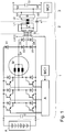
- FIG. 1 A device according to the invention is shown with a schematic circuit diagram.
- an inverter for supplying the electric motor M is provided from the energy stores B and C connected in parallel, which are preferably designed as a battery and / or capacitor.
- the stator windings of the electric motor M are designed as a three-phase winding with a star point connection.
- the electric motor can be supplied with a feed frequency that can be determined by the inverter, that is to say a three-phase voltage system rotating at this feed frequency, and in this way the speed of the electric motor can be controlled or, alternatively, when a rotation angle or speed sensor is attached, it can be regulated to a desired speed or a desired torque.
- the energy generated by the electric motor M can be fed to the energy store via the inverter.
- the inverter consists of three half-bridges, that is to say pairs of branches, each of which comprises a series connection of an upper and lower controllable semiconductor switch, each of which in turn has a diode connected in parallel.
- the semiconductor switches are preferably controlled with pulse width modulation.
- the control electronics A generates the control signals for the semiconductor switches. In motor operation, a three-phase voltage system with a predeterminable frequency is thus supplied to the motor M, and the motor M is thus set in rotation.
- energy can be supplied from the motor via the inverter to the energy stores B and C and can therefore be loaded.
- the loading can also be carried out when the motor M is not rotating.
- a primary winding L2 can be brought into inductive coupling with a secondary winding L1 from the outside.
- This secondary winding L1 is part of a charging unit 2, which is connected to the rest of the motor-converter unit 1.
- the primary winding is fed by a gyrator G, which in turn is fed by a single-phase inverter which comprises the switches S1, S2, S3, S4 and which is fed by the direct voltage applied to the capacitor C2.
- the gyrator G converts the voltage source-like behavior of the output side of the single-phase inverter into a current source-like behavior towards the secondary winding L1.
- a short-circuiting device R is provided in parallel with the secondary winding to switch off the supplied energy. If this short-circuiting device R is open, the secondary alternating current de rectifier, comprising the diodes D2, D3, D4, D5, is supplied and the rectified current is supplied to the energy stores B and C via the diode D1.
- the inverter is used to end the loading by placing one or more lower switches of the inverter, that is to say switches at the lower potential of the energy stores in the conductive ones State are offset, whereby the rectified alternating current is derived via the star point (SP) of the motor M and the one or more stator windings of the motor M and the lower switch or switches.
- SP star point
- stator windings reduce high-frequency components and contribute to smoothing.
- Charging of the energy store is also possible if the voltage SP present at the star point is less than the required charging voltage. Then, by means of the inductances of the stator winding, step-up converter operation is made possible.
- the motor with inverter is not only used for mere rectification but also operated as a step-up converter.
- the switches are controlled accordingly, so that a much higher voltage can be generated at the energy store than the peak voltage value of the unipolar voltage that can be generated by the rectifier.
- the inductances of the stator windings cause switching operations of the semiconductor switches Inverters together and make the level of voltage at the energy store controllable or adjustable when attaching a means for detecting the voltage at the energy store.
- An important parameter here is the switching frequency of the switches in the inverter. Despite a mains voltage, the peak value and / or effective value of which is smaller than the charging voltage required for the energy store, charging of the energy store is therefore possible.
- the inverter In the motor and / or generator operation of the motor, the inverter is controlled in such a way that a three-phase voltage is applied to the motor.
- the control signals are thus dependent on one another, so that the three-phase voltage is applied to the stator windings.
- the control signals for the switches of the half bridges may be generated independently of one another.
- the control of the three half-bridges, i.e. pairs of branches, of the inverter can be carried out synchronously. With an asynchronous execution of the control signals, a further improved, more uniform utilization of the switches is made possible.
- Asynchronous here means that the control signals assigned to the respective half bridges have a different frequency and are therefore not synchronous with one another.
- a holding torque is generated in the electric motor by means of the unipolar current, which is generated when loading the energy store and step-up converter operation, in particular when it is designed as a synchronous motor.
- the battery can be protected against overcharging or overvoltage by closing the lower switches of the inverter.
- a further electronic switch is provided, which is provided between the star point and the lower potential or alternatively between one of the motor connections and the lower potential, that is to say is arranged in parallel with one of the lower switches.
- this further switch is designed as a thyristor
- a passive circuit for example comprising a Zener diode or the like, can be carried out, with which the current can be diverted from the star point into the lower potential of the energy stores B and C once a critical voltage is exceeded, which is greater than the critical voltage above which the lower switches of the inverter are closed.
- the switches of the inverter are controlled in a block-commutated manner instead of pulse-width modulated by the in Figure 1 Control not shown.
- the energy store can be supplied in the manner described, so that the capacity of the energy store is used up more slowly, that is to say the above-mentioned charging current can be used for at least partially feeding the inverter.
- the stator windings and the diodes of the rectifier must be dimensioned accordingly robust.
- a plurality of inverters are supplied from the energy store, each of which feeds an electric motor, with the energy store in the manner described above, each having a switch for the controlled supply of current to the respective stator winding, via a stator winding of a first or more electric motors.
- an additional inductance L is inserted between the star point (SP) and the rectifier (D2, D3, D4, D5), the current of which can be influenced by a controllable switch.
- the switch essentially works in accordance with a buck converter, although at least the stator windings and the inductance L at the star point of the stator windings are provided as inductors and the inverter with energy storage is effective as a load.
- a diode is connected in parallel to the switch, preferably a semiconductor switch, this parallel connection being connected to the lower potential of the unipolar voltage via the diode connected in series.
- stator windings have a smoothing effect on the current supplied via the switch and also represent an additional energy store.
Landscapes
- Engineering & Computer Science (AREA)
- Power Engineering (AREA)
- Transportation (AREA)
- Mechanical Engineering (AREA)
- Computer Networks & Wireless Communication (AREA)
- Life Sciences & Earth Sciences (AREA)
- Sustainable Development (AREA)
- Sustainable Energy (AREA)
- Control Of Ac Motors In General (AREA)
- Control Of Eletrric Generators (AREA)
- Control Of Multiple Motors (AREA)
- Electric Propulsion And Braking For Vehicles (AREA)
Claims (9)
- Système d'entraînement comprenant un moteur électrique (M), un onduleur, un accumulateur d'énergie (B, C),
dans lequel l'onduleur est constitué de trois demi-ponts formés chacun d'un montage en série de deux commutateurs à semi-conducteurs,
dans lequel le moteur électrique peut être alimenté par l'onduleur qui peut être alimenté à partir de l'accumulateur d'énergie (B, C),
dans lequel le moteur électrique (M) est réalisé sous la forme d'un moteur triphasé à montage en étoile,
dans lequel les enroulements statoriques du moteur électrique sont câblés en étoile, dans lequel un courant peut être amené au point neutre (SP) du moteur électrique (M) à partir d'un redresseur (D2, D3, D4, D5) qui est alimenté par un enroulement secondaire (L1),
dans lequel l'enroulement secondaire (L1) peut être alimenté à partir d'un enroulement primaire (L2) qui est couplé par induction à l'enroulement secondaire (L1),
lorsqu'une première valeur critique de la tension au point neutre (SP) est dépassée, le courant de charge est conduit par l'intermédiaire d'une diode (Dl) directement du redresseur (D2, D3, D4, D5) vers le ou les accumulateurs d'énergie (B, C),
dans lequel la première valeur critique correspond à la tension de charge pour le ou les accumulateurs d'énergie (B, C),
dans lequel l'enroulement primaire (L2) est alimenté à partir d'un convertisseur tension-courant, en particulier d'un gyrateur, qui est alimenté en tension alternative par un onduleur,
dans lequel le convertisseur tension-courant comprend au moins un condensateur et une inductance de telle sorte que la fréquence de résonance associée corresponde sensiblement à la fréquence de la tension alternative, le condensateur et l'inductance étant en particulier montés en série,
dans lequel, lorsque la tension au point neutre (SP) devient inférieure à la première valeur critique de la tension, le courant de charge est conduit du redresseur (D2, D3, D4, D5) vers le ou les accumulateurs d'énergie (B, C) par l'intermédiaire d'au moins un enroulement statorique et de l'onduleur, l'onduleur pouvant fonctionner avec les enroulements statoriques comme transformateur élévateur,
dans lequel, lorsqu'une deuxième valeur critique qui est supérieure à la première valeur critique est dépassée, un commutateur, par lequel un courant est dérivé du point neutre (SP) vers le potentiel inférieur, est fermé, en particulier pour protéger les accumulateurs d'énergie (B, C) contre une surcharge. - Système d'entraînement selon la revendication 1,
caractérisé en ce
qu'au moins un accumulateur d'énergie (B, C) est réalisé sous la forme d'un condensateur, d'un supercondensateur et/ou d'une batterie. - Système d'entraînement selon au moins l'une des revendications précédentes,
caractérisé en ce
qu'une inductance supplémentaire est prévue entre le point neutre (SP) et le redresseur (D2, D3, D4, D5) qui alimente ce dernier. - Système d'entraînement selon au moins l'une des revendications précédentes,
caractérisé en ce que
l'onduleur forme avec un enroulement statorique ou les enroulements statoriques, en particulier avec l'inductance supplémentaire, un transformateur élévateur, en particulier auquel un courant est amené à partir du redresseur (D2, D3, D4, D5) et qui met un courant de charge à la disposition des accumulateurs d'énergie (B, C). - Système d'entraînement selon au moins l'une des revendications précédentes,
caractérisé en ce que
la valeur efficace ou la valeur de crête de la tension qui alimente le redresseur (D2, D3, D4, D5) et apparaît à l'enroulement secondaire (L1) est inférieure à la tension de charge pour l'accumulateur d'énergie (B, C), en particulier donc inférieure à la tension nécessaire pour charger l'accumulateur d'énergie (B, C), en particulier à la tension d'entrée de l'onduleur. - Procédé de fonctionnement d'un système d'entraînement selon au moins l'une des revendications précédentes,
comprenant un moteur électrique pouvant être alimenté à partir d'un accumulateur d'énergie (B, C),
dans lequel le moteur électrique fonctionne en montage en étoile,
dans lequel un courant est amené au point neutre (SP) du moteur électrique à partir d'un redresseur (D2, D3, D4, D5) qui est alimenté par un enroulement secondaire (L1),
dans lequel l'enroulement secondaire (L1) est alimenté sans contact à partir d'un enroulement primaire (L2),
dans lequel un courant de charge pour l'accumulateur d'énergie (B, C) est formé à partir d'un onduleur par l'intermédiaire duquel les enroulements statoriques du moteur électrique peuvent être alimentés, en particulier avec un système de tension triphasée qui est produit en fonctionnement en moteur lorsque l'onduleur est alimenté à partir de l'accumulateur d'énergie (B, C),
tant que la tension au point neutre (SP) est inférieure à une première valeur critique, dans lequel le courant de charge est amené à l'accumulateur d'énergie (B, C) directement à partir du redresseur (D2, D3, D4, D5) par l'intermédiaire d'une diode (Dl) tant que la tension au point neutre (SP) est supérieure à la première valeur critique,
dans lequel au moins l'un des commutateurs inférieurs de l'onduleur est mis dans l'état conducteur, de sorte qu'un courant provenant du redresseur (D2, D3, D4, D5) est dérivé par l'enroulement statorique associé vers le potentiel inférieur de l'accumulateur d'énergie (B, C), en particulier donc l'accumulateur d'énergie (B, C) est protégé contre le courant provenant du redresseur (D2, D3, D4, D5) tant que la tension au point neutre (SP) est supérieure à une deuxième valeur critique qui est supérieure à la première valeur critique et à partir du dépassement de laquelle l'accumulateur d'énergie (B, C) est menacé avec une certaine probabilité. - Procédé selon la revendication 6,
caractérisé en ce qu'un autre trajet de courant est libéré, par lequel un courant provenant du redresseur (D2, D3, D4, D5) est dérivé directement ou par l'intermédiaire de l'enroulement statorique associé vers le potentiel inférieur de l'accumulateur d'énergie (B, C), en particulier donc l'accumulateur d'énergie (B, C) est protégé contre le courant du redresseur (D2, D3, D4, D5) tant que la tension au point neutre (SP) est supérieure à une troisième valeur critique qui est supérieure à la deuxième valeur critique et à partir du dépassement de laquelle l'accumulateur d'énergie (B, C) est menacé avec une plus grande probabilité,
en particulier dans lequel l'autre trajet de courant est formé d'un circuit passif, en particulier dans lequel l'autre trajet de courant comprend un thyristor dans le trajet de commande duquel est prévue une diode Zener ou un composant correspondant qui présente un comportement du type à seuil de commutation. - Procédé selon la revendication 6 ou 7,
caractérisé en ce que
l'onduleur est commandé par modulation de largeur d'impulsion ou par commutation par blocs, en particulier pour le fonctionnement en moteur ou en générateur du moteur électrique,
et/ou que
l'onduleur est polyphasé et, lors de la charge de l'accumulateur d'énergie (B, C), les signaux de commande pour les commutateurs de l'onduleur sont synchrones, synchrones avec décalage dans le temps ou asynchrones. - Procédé selon la revendication 6, 8 ou 7,
caractérisé en ce que
la recharge de l'accumulateur d'énergie (B, C) est répétée cycliquement, en particulier la recharge est effectuée en alternance avec le fonctionnement en moteur ou en générateur du moteur électrique.
Applications Claiming Priority (2)
| Application Number | Priority Date | Filing Date | Title |
|---|---|---|---|
| DE102009014704A DE102009014704A1 (de) | 2009-03-27 | 2009-03-27 | Antriebssystem, Verfahren zum Betreiben eines Antriebssystems und Verwendung |
| PCT/EP2010/001661 WO2010108623A1 (fr) | 2009-03-27 | 2010-03-17 | Système d'entraînement, procédé de fonctionnement d'un système d'entraînement et utilisation de celui-ci |
Publications (2)
| Publication Number | Publication Date |
|---|---|
| EP2411240A1 EP2411240A1 (fr) | 2012-02-01 |
| EP2411240B1 true EP2411240B1 (fr) | 2020-01-08 |
Family
ID=42237006
Family Applications (1)
| Application Number | Title | Priority Date | Filing Date |
|---|---|---|---|
| EP10709696.8A Active EP2411240B1 (fr) | 2009-03-27 | 2010-03-17 | Systeme d'entrainement electrique, son procédé de fonctionnement |
Country Status (5)
| Country | Link |
|---|---|
| US (1) | US8912738B2 (fr) |
| EP (1) | EP2411240B1 (fr) |
| CN (1) | CN102365188B (fr) |
| DE (1) | DE102009014704A1 (fr) |
| WO (1) | WO2010108623A1 (fr) |
Families Citing this family (30)
| Publication number | Priority date | Publication date | Assignee | Title |
|---|---|---|---|---|
| KR101189237B1 (ko) * | 2010-07-09 | 2012-10-09 | 현대자동차주식회사 | 하이브리드 자동차의 충전장치 및 방법 |
| DE102010041068A1 (de) * | 2010-09-20 | 2012-03-22 | Robert Bosch Gmbh | System zum Laden eines Energiespeichers und Verfahren zum Betrieb des Ladesystems |
| DE102010064325A1 (de) * | 2010-12-29 | 2012-07-05 | Robert Bosch Gmbh | System mit einer elektrischen Maschine |
| GB2499452A (en) * | 2012-02-17 | 2013-08-21 | Bombardier Transp Gmbh | Receiving device for an inductively charged electric vehicle |
| CN102624030A (zh) * | 2012-03-29 | 2012-08-01 | 东南大学 | 一种光伏/蓄电池混合式电流逆变型分布发电系统 |
| CN104247214B (zh) | 2012-04-23 | 2017-05-24 | 三菱电机株式会社 | 永磁体型旋转电机及车辆驱动系统 |
| DE102012207809A1 (de) * | 2012-05-10 | 2013-11-14 | Robert Bosch Gmbh | Reichweitenverlängerer, Antrieb und Kraftfahrzeug |
| CN103009989B (zh) * | 2012-12-14 | 2015-09-16 | 东南大学 | 一种混合式电流源型能量传输与驱动设备 |
| US9376025B2 (en) * | 2013-02-06 | 2016-06-28 | Lg Electronics Inc. | Charging apparatus and electric vehicle including the same |
| DE112013006795T5 (de) * | 2013-04-09 | 2015-12-03 | Mitsubishi Electric Corporation | Mehrachs-Treiber-Vorrichtung |
| DE102013219670A1 (de) | 2013-09-30 | 2015-04-02 | Robert Bosch Gmbh | Inverterschaltung |
| JP6242226B2 (ja) * | 2014-02-04 | 2017-12-06 | 有限会社ティ辞書企画 | 検索装置、検索方法、及びプログラム |
| CN104362769B (zh) * | 2014-11-06 | 2017-03-01 | 华中科技大学 | 一种无线输能系统 |
| EP3295537B1 (fr) * | 2015-05-13 | 2020-04-15 | Black & Decker Inc. | Charge de batterie embarquée et freinage par récupération |
| JPWO2017115625A1 (ja) * | 2015-12-28 | 2018-10-18 | 日本電産株式会社 | 移動体システム |
| DE102016209905A1 (de) * | 2016-06-06 | 2016-12-29 | Continental Automotive Gmbh | Fahrzeugbordnetz mit Wechselrichter, Energiespeicher, elektrischer Maschine und Gleichstrom-Übertragungsanschluss |
| JP2017011993A (ja) * | 2016-08-08 | 2017-01-12 | 日立オートモティブシステムズ株式会社 | 充電器 |
| DE102017123346A1 (de) * | 2017-10-09 | 2019-04-11 | Dr. Ing. H.C. F. Porsche Aktiengesellschaft | Verfahren zum Initialisieren eines DC-Ladevorgangs einer Batterie mittels eines Inverters |
| WO2019076483A1 (fr) * | 2017-10-18 | 2019-04-25 | Sew-Eurodrive Gmbh & Co. Kg | Chargeur et système de transmission d'énergie vers une unité mobile ayant un accumulateur d'énergie et un enroulement secondaire |
| DE102018201340B3 (de) * | 2018-01-30 | 2019-06-13 | Bayerische Motoren Werke Aktiengesellschaft | Verfahren zum Betreiben einer Drehfeldmaschine eines Kraftfahrzeugs, Übertragungsvorrichtung, Antriebseinheit sowie Kraftfahrzeug |
| CN110971173B (zh) * | 2018-12-21 | 2021-01-19 | 比亚迪股份有限公司 | 动力电池的充电方法、电机控制电路及车辆 |
| CN111347887B (zh) | 2018-12-21 | 2021-06-18 | 比亚迪股份有限公司 | 电机驱动装置、控制方法、车辆及可读存储介质 |
| CN111347901A (zh) * | 2018-12-21 | 2020-06-30 | 比亚迪股份有限公司 | 一种车辆、充电装置、电机控制电路 |
| DE102019001936A1 (de) | 2019-03-20 | 2020-09-24 | Günther Zimmer | Energieversorgungssystem für ein Transport- und/oder Bearbeitungssystem |
| CN112224042B (zh) * | 2019-06-30 | 2022-04-15 | 比亚迪股份有限公司 | 能量转换装置及车辆 |
| KR20210133374A (ko) * | 2020-04-28 | 2021-11-08 | 현대자동차주식회사 | 모터 구동 시스템을 이용한 충전 시스템 및 방법 |
| CN116018743A (zh) * | 2020-08-14 | 2023-04-25 | 思睿逻辑国际半导体有限公司 | 具有串联耦合功率转换器的无线功率架构 |
| EP3988377B1 (fr) * | 2020-10-23 | 2024-01-03 | Ningbo Geely Automobile Research & Development Co. Ltd. | Système électrique de véhicule |
| SE545580C2 (en) * | 2021-04-26 | 2023-10-31 | Borgwarner Sweden Ab | Charging circuit for an energy storage device of a vehicle |
| DE102022200577A1 (de) | 2022-01-19 | 2023-07-20 | Zf Friedrichshafen Ag | Antriebsvorrichtung und Verfahren zum Betreiben einer Antriebsvorrichtung für ein Fahrzeug |
Citations (2)
| Publication number | Priority date | Publication date | Assignee | Title |
|---|---|---|---|---|
| DD114729A1 (fr) * | 1974-09-19 | 1975-08-12 | ||
| JPH1198713A (ja) * | 1997-09-25 | 1999-04-09 | Aisin Aw Co Ltd | 充電制御装置及び充電制御方法 |
Family Cites Families (18)
| Publication number | Priority date | Publication date | Assignee | Title |
|---|---|---|---|---|
| JPS5334491Y2 (fr) * | 1972-02-19 | 1978-08-24 | ||
| DE3415145A1 (de) * | 1984-04-21 | 1985-10-31 | Mitec Moderne Ind Gmbh | Wechselrichter |
| DE4107391A1 (de) * | 1991-03-08 | 1992-09-10 | Abb Patent Gmbh | Elektrofahrzeug mit mindestens einem batteriegespeisten wechselrichter |
| DE4128962A1 (de) * | 1991-08-29 | 1993-03-04 | Leonhard Kuffer | Elektronische hilfsschaltungen zur verarbeitung von elektrischer energie, die von wind-, solar-, und anderen generatoren erzeugt wird |
| US5341280A (en) * | 1991-09-27 | 1994-08-23 | Electric Power Research Institute | Contactless coaxial winding transformer power transfer system |
| JP3284571B2 (ja) * | 1992-01-24 | 2002-05-20 | 株式会社明電舎 | 電気自動車 |
| JPH07115704A (ja) * | 1993-10-14 | 1995-05-02 | Toyota Motor Corp | リターダ装置 |
| JPH08103004A (ja) * | 1994-09-30 | 1996-04-16 | Kansai Electric Power Co Inc:The | バッテリ充電装置兼用モータ駆動装置及び電気自動車 |
| JP3741171B2 (ja) * | 1996-06-17 | 2006-02-01 | 株式会社安川電機 | 多重パルス幅変調方式の電力変換装置 |
| EP0834977A3 (fr) * | 1996-08-08 | 1999-04-14 | Schmidhauser AG | Dispositif de charge pour au moins une batterie, en particulier une batterie pour un véhicule électrique, et méthode de fonctionnement de ce dispositif |
| AU8776598A (en) | 1997-08-08 | 1999-03-01 | Jurgen G. Meins | Method and apparatus for supplying contactless power |
| JP3219039B2 (ja) * | 1997-12-15 | 2001-10-15 | 富士電機株式会社 | 電気自動車の電気システム |
| JP4134509B2 (ja) * | 2000-11-27 | 2008-08-20 | トヨタ自動車株式会社 | 充電装置および電動車輌 |
| US7164591B2 (en) * | 2003-10-01 | 2007-01-16 | International Rectifier Corporation | Bridge-less boost (BLB) power factor correction topology controlled with one cycle control |
| FR2864372A1 (fr) * | 2003-12-19 | 2005-06-24 | Hispano Suiza Sa | Convertisseur 12 alternances comportant une self de filtrage integre au redresseur |
| KR100547289B1 (ko) * | 2005-05-18 | 2006-01-26 | 주식회사 피에스텍 | 간헐 모드로 동작하는 동기 정류형 직렬 공진 컨버터 |
| DE102006022223A1 (de) * | 2006-05-11 | 2007-11-15 | Sew-Eurodrive Gmbh & Co. Kg | Anlagenteil und Anlage |
| DE102006043960B4 (de) * | 2006-09-14 | 2021-01-21 | Sew-Eurodrive Gmbh & Co Kg | System zur berührungslosen Energieübertragung |
-
2009
- 2009-03-27 DE DE102009014704A patent/DE102009014704A1/de active Pending
-
2010
- 2010-03-17 WO PCT/EP2010/001661 patent/WO2010108623A1/fr active Application Filing
- 2010-03-17 CN CN201080015344.XA patent/CN102365188B/zh active Active
- 2010-03-17 EP EP10709696.8A patent/EP2411240B1/fr active Active
- 2010-03-17 US US13/260,688 patent/US8912738B2/en active Active
Patent Citations (2)
| Publication number | Priority date | Publication date | Assignee | Title |
|---|---|---|---|---|
| DD114729A1 (fr) * | 1974-09-19 | 1975-08-12 | ||
| JPH1198713A (ja) * | 1997-09-25 | 1999-04-09 | Aisin Aw Co Ltd | 充電制御装置及び充電制御方法 |
Also Published As
| Publication number | Publication date |
|---|---|
| WO2010108623A1 (fr) | 2010-09-30 |
| US8912738B2 (en) | 2014-12-16 |
| DE102009014704A1 (de) | 2010-10-07 |
| EP2411240A1 (fr) | 2012-02-01 |
| CN102365188A (zh) | 2012-02-29 |
| WO2010108623A8 (fr) | 2010-12-02 |
| US20120019174A1 (en) | 2012-01-26 |
| CN102365188B (zh) | 2015-04-29 |
Similar Documents
| Publication | Publication Date | Title |
|---|---|---|
| EP2411240B1 (fr) | Systeme d'entrainement electrique, son procédé de fonctionnement | |
| EP3286033B1 (fr) | Circuit de puissance pour l'alimentation électrique dans un véhicule à propulsion électrique et système d'alimentation en énergie fixe | |
| EP3295538A1 (fr) | Circuit de charge côté véhicule pour un véhicule à entraînement électrique et procédé de fonctionnement d'un convertisseur côté véhicule ainsi qu'emploi d'au moins un enroulement d'une machine électrique côté véhicule pour un stockage intermédiaire | |
| DE112009001695B4 (de) | Stromversorgungsvorrichtung | |
| DE102009017087B4 (de) | Verfahren zum Beladen eines Energiespeichers | |
| EP3507129B1 (fr) | Système d'entraînement, en particulier pour un véhicule et procédé de mise en chauffe d'un système d'entraînement | |
| DE112016001870T5 (de) | Leistungsversorgungsvorrichtung | |
| EP2416982A1 (fr) | Transmission de puissance bidirectionnelle et sans contact pour la charge de véhicules électriques | |
| EP2394358B1 (fr) | Système d'entraînement, procédé de fonctionnement d'un système d'entraînement et utilisation | |
| EP2812989B1 (fr) | Système d'entraînement doté d'un accumulateur d'énergie et procédé de fonctionnement d'un système d'entraînement | |
| EP1497913B1 (fr) | Systeme convertisseur, procede et convertisseur | |
| EP2623363B1 (fr) | Dispositif et procédé de chargement d'une batterie de traction d'un véhicule électrique | |
| DE102017206497B4 (de) | Ladevorrichtung und Verfahren zum Laden eines elektrischen Energiespeichers eines Fahrzeugs, sowie Kraftfahrzeug | |
| DE102013006964B4 (de) | Vorrichtung mit Energiespeicher und Wechselrichter und Verfahren zum Betreiben einer Vorrichtung | |
| DE102017006819A1 (de) | System und Verfahren zum Betreiben eines Systems | |
| WO2013143847A2 (fr) | Système d'accumulation d'énergie équipé d'éléments refroidisseurs et procédé de refroidissement d'éléments accumulateurs d'énergie | |
| DE102009021797B4 (de) | Fahrzeug mit Ladeanordnung für einen Energiespeicher des Fahrzeugs | |
| EP2774262B1 (fr) | Procédé destiné à la commande d'un convertisseur de puissance | |
| WO2020169575A1 (fr) | Réseau de bord de véhicule comprenant un accumulateur, un raccord de tension alternative et un raccord de tension continue | |
| DE102012206801A1 (de) | Schaltung mit einer stromrichterschaltung und verfahren zur leistungsanpassung | |
| WO2013092053A1 (fr) | Procédé pour décharger au moins un condensateur de circuit intermédiaire | |
| EP2577837B1 (fr) | Dispositif et procédé servant à faire fonctionner un dispositif | |
| EP3365963B1 (fr) | Installation, comportant un réseau, un filtre et plusieurs dispositifs d'entraînement |
Legal Events
| Date | Code | Title | Description |
|---|---|---|---|
| PUAI | Public reference made under article 153(3) epc to a published international application that has entered the european phase |
Free format text: ORIGINAL CODE: 0009012 |
|
| 17P | Request for examination filed |
Effective date: 20111027 |
|
| AK | Designated contracting states |
Kind code of ref document: A1 Designated state(s): AT BE BG CH CY CZ DE DK EE ES FI FR GB GR HR HU IE IS IT LI LT LU LV MC MK MT NL NO PL PT RO SE SI SK SM TR |
|
| DAX | Request for extension of the european patent (deleted) | ||
| STAA | Information on the status of an ep patent application or granted ep patent |
Free format text: STATUS: EXAMINATION IS IN PROGRESS |
|
| 17Q | First examination report despatched |
Effective date: 20181025 |
|
| REG | Reference to a national code |
Ref country code: DE Ref legal event code: R079 Ref document number: 502010016447 Country of ref document: DE Free format text: PREVIOUS MAIN CLASS: B60L0011180000 Ipc: H02J0005000000 |
|
| GRAP | Despatch of communication of intention to grant a patent |
Free format text: ORIGINAL CODE: EPIDOSNIGR1 |
|
| STAA | Information on the status of an ep patent application or granted ep patent |
Free format text: STATUS: GRANT OF PATENT IS INTENDED |
|
| RIC1 | Information provided on ipc code assigned before grant |
Ipc: H02J 7/02 20160101ALI20190805BHEP Ipc: H02J 5/00 20160101AFI20190805BHEP Ipc: B60L 53/22 20190101ALI20190805BHEP |
|
| INTG | Intention to grant announced |
Effective date: 20190822 |
|
| GRAS | Grant fee paid |
Free format text: ORIGINAL CODE: EPIDOSNIGR3 |
|
| GRAA | (expected) grant |
Free format text: ORIGINAL CODE: 0009210 |
|
| STAA | Information on the status of an ep patent application or granted ep patent |
Free format text: STATUS: THE PATENT HAS BEEN GRANTED |
|
| AK | Designated contracting states |
Kind code of ref document: B1 Designated state(s): AT BE BG CH CY CZ DE DK EE ES FI FR GB GR HR HU IE IS IT LI LT LU LV MC MK MT NL NO PL PT RO SE SI SK SM TR |
|
| REG | Reference to a national code |
Ref country code: GB Ref legal event code: FG4D Free format text: NOT ENGLISH |
|
| REG | Reference to a national code |
Ref country code: CH Ref legal event code: EP |
|
| REG | Reference to a national code |
Ref country code: DE Ref legal event code: R096 Ref document number: 502010016447 Country of ref document: DE |
|
| REG | Reference to a national code |
Ref country code: IE Ref legal event code: FG4D Free format text: LANGUAGE OF EP DOCUMENT: GERMAN |
|
| REG | Reference to a national code |
Ref country code: AT Ref legal event code: REF Ref document number: 1223866 Country of ref document: AT Kind code of ref document: T Effective date: 20200215 |
|
| REG | Reference to a national code |
Ref country code: NL Ref legal event code: MP Effective date: 20200108 |
|
| REG | Reference to a national code |
Ref country code: LT Ref legal event code: MG4D |
|
| PG25 | Lapsed in a contracting state [announced via postgrant information from national office to epo] |
Ref country code: PT Free format text: LAPSE BECAUSE OF FAILURE TO SUBMIT A TRANSLATION OF THE DESCRIPTION OR TO PAY THE FEE WITHIN THE PRESCRIBED TIME-LIMIT Effective date: 20200531 Ref country code: NO Free format text: LAPSE BECAUSE OF FAILURE TO SUBMIT A TRANSLATION OF THE DESCRIPTION OR TO PAY THE FEE WITHIN THE PRESCRIBED TIME-LIMIT Effective date: 20200408 Ref country code: FI Free format text: LAPSE BECAUSE OF FAILURE TO SUBMIT A TRANSLATION OF THE DESCRIPTION OR TO PAY THE FEE WITHIN THE PRESCRIBED TIME-LIMIT Effective date: 20200108 Ref country code: NL Free format text: LAPSE BECAUSE OF FAILURE TO SUBMIT A TRANSLATION OF THE DESCRIPTION OR TO PAY THE FEE WITHIN THE PRESCRIBED TIME-LIMIT Effective date: 20200108 Ref country code: LT Free format text: LAPSE BECAUSE OF FAILURE TO SUBMIT A TRANSLATION OF THE DESCRIPTION OR TO PAY THE FEE WITHIN THE PRESCRIBED TIME-LIMIT Effective date: 20200108 |
|
| PG25 | Lapsed in a contracting state [announced via postgrant information from national office to epo] |
Ref country code: IS Free format text: LAPSE BECAUSE OF FAILURE TO SUBMIT A TRANSLATION OF THE DESCRIPTION OR TO PAY THE FEE WITHIN THE PRESCRIBED TIME-LIMIT Effective date: 20200508 Ref country code: GR Free format text: LAPSE BECAUSE OF FAILURE TO SUBMIT A TRANSLATION OF THE DESCRIPTION OR TO PAY THE FEE WITHIN THE PRESCRIBED TIME-LIMIT Effective date: 20200409 Ref country code: BG Free format text: LAPSE BECAUSE OF FAILURE TO SUBMIT A TRANSLATION OF THE DESCRIPTION OR TO PAY THE FEE WITHIN THE PRESCRIBED TIME-LIMIT Effective date: 20200408 Ref country code: SE Free format text: LAPSE BECAUSE OF FAILURE TO SUBMIT A TRANSLATION OF THE DESCRIPTION OR TO PAY THE FEE WITHIN THE PRESCRIBED TIME-LIMIT Effective date: 20200108 Ref country code: LV Free format text: LAPSE BECAUSE OF FAILURE TO SUBMIT A TRANSLATION OF THE DESCRIPTION OR TO PAY THE FEE WITHIN THE PRESCRIBED TIME-LIMIT Effective date: 20200108 Ref country code: HR Free format text: LAPSE BECAUSE OF FAILURE TO SUBMIT A TRANSLATION OF THE DESCRIPTION OR TO PAY THE FEE WITHIN THE PRESCRIBED TIME-LIMIT Effective date: 20200108 |
|
| REG | Reference to a national code |
Ref country code: DE Ref legal event code: R097 Ref document number: 502010016447 Country of ref document: DE |
|
| PG25 | Lapsed in a contracting state [announced via postgrant information from national office to epo] |
Ref country code: DK Free format text: LAPSE BECAUSE OF FAILURE TO SUBMIT A TRANSLATION OF THE DESCRIPTION OR TO PAY THE FEE WITHIN THE PRESCRIBED TIME-LIMIT Effective date: 20200108 Ref country code: ES Free format text: LAPSE BECAUSE OF FAILURE TO SUBMIT A TRANSLATION OF THE DESCRIPTION OR TO PAY THE FEE WITHIN THE PRESCRIBED TIME-LIMIT Effective date: 20200108 Ref country code: MC Free format text: LAPSE BECAUSE OF FAILURE TO SUBMIT A TRANSLATION OF THE DESCRIPTION OR TO PAY THE FEE WITHIN THE PRESCRIBED TIME-LIMIT Effective date: 20200108 Ref country code: SK Free format text: LAPSE BECAUSE OF FAILURE TO SUBMIT A TRANSLATION OF THE DESCRIPTION OR TO PAY THE FEE WITHIN THE PRESCRIBED TIME-LIMIT Effective date: 20200108 Ref country code: EE Free format text: LAPSE BECAUSE OF FAILURE TO SUBMIT A TRANSLATION OF THE DESCRIPTION OR TO PAY THE FEE WITHIN THE PRESCRIBED TIME-LIMIT Effective date: 20200108 Ref country code: SM Free format text: LAPSE BECAUSE OF FAILURE TO SUBMIT A TRANSLATION OF THE DESCRIPTION OR TO PAY THE FEE WITHIN THE PRESCRIBED TIME-LIMIT Effective date: 20200108 Ref country code: CZ Free format text: LAPSE BECAUSE OF FAILURE TO SUBMIT A TRANSLATION OF THE DESCRIPTION OR TO PAY THE FEE WITHIN THE PRESCRIBED TIME-LIMIT Effective date: 20200108 Ref country code: RO Free format text: LAPSE BECAUSE OF FAILURE TO SUBMIT A TRANSLATION OF THE DESCRIPTION OR TO PAY THE FEE WITHIN THE PRESCRIBED TIME-LIMIT Effective date: 20200108 |
|
| REG | Reference to a national code |
Ref country code: CH Ref legal event code: PL |
|
| PLBE | No opposition filed within time limit |
Free format text: ORIGINAL CODE: 0009261 |
|
| STAA | Information on the status of an ep patent application or granted ep patent |
Free format text: STATUS: NO OPPOSITION FILED WITHIN TIME LIMIT |
|
| 26N | No opposition filed |
Effective date: 20201009 |
|
| REG | Reference to a national code |
Ref country code: BE Ref legal event code: MM Effective date: 20200331 |
|
| PG25 | Lapsed in a contracting state [announced via postgrant information from national office to epo] |
Ref country code: LU Free format text: LAPSE BECAUSE OF NON-PAYMENT OF DUE FEES Effective date: 20200317 |
|
| PG25 | Lapsed in a contracting state [announced via postgrant information from national office to epo] |
Ref country code: IT Free format text: LAPSE BECAUSE OF FAILURE TO SUBMIT A TRANSLATION OF THE DESCRIPTION OR TO PAY THE FEE WITHIN THE PRESCRIBED TIME-LIMIT Effective date: 20200108 Ref country code: IE Free format text: LAPSE BECAUSE OF NON-PAYMENT OF DUE FEES Effective date: 20200317 Ref country code: CH Free format text: LAPSE BECAUSE OF NON-PAYMENT OF DUE FEES Effective date: 20200331 Ref country code: LI Free format text: LAPSE BECAUSE OF NON-PAYMENT OF DUE FEES Effective date: 20200331 |
|
| PG25 | Lapsed in a contracting state [announced via postgrant information from national office to epo] |
Ref country code: BE Free format text: LAPSE BECAUSE OF NON-PAYMENT OF DUE FEES Effective date: 20200331 Ref country code: PL Free format text: LAPSE BECAUSE OF FAILURE TO SUBMIT A TRANSLATION OF THE DESCRIPTION OR TO PAY THE FEE WITHIN THE PRESCRIBED TIME-LIMIT Effective date: 20200108 Ref country code: SI Free format text: LAPSE BECAUSE OF FAILURE TO SUBMIT A TRANSLATION OF THE DESCRIPTION OR TO PAY THE FEE WITHIN THE PRESCRIBED TIME-LIMIT Effective date: 20200108 |
|
| REG | Reference to a national code |
Ref country code: AT Ref legal event code: MM01 Ref document number: 1223866 Country of ref document: AT Kind code of ref document: T Effective date: 20200317 |
|
| PG25 | Lapsed in a contracting state [announced via postgrant information from national office to epo] |
Ref country code: AT Free format text: LAPSE BECAUSE OF NON-PAYMENT OF DUE FEES Effective date: 20200317 |
|
| PG25 | Lapsed in a contracting state [announced via postgrant information from national office to epo] |
Ref country code: TR Free format text: LAPSE BECAUSE OF FAILURE TO SUBMIT A TRANSLATION OF THE DESCRIPTION OR TO PAY THE FEE WITHIN THE PRESCRIBED TIME-LIMIT Effective date: 20200108 Ref country code: MT Free format text: LAPSE BECAUSE OF FAILURE TO SUBMIT A TRANSLATION OF THE DESCRIPTION OR TO PAY THE FEE WITHIN THE PRESCRIBED TIME-LIMIT Effective date: 20200108 Ref country code: CY Free format text: LAPSE BECAUSE OF FAILURE TO SUBMIT A TRANSLATION OF THE DESCRIPTION OR TO PAY THE FEE WITHIN THE PRESCRIBED TIME-LIMIT Effective date: 20200108 |
|
| PG25 | Lapsed in a contracting state [announced via postgrant information from national office to epo] |
Ref country code: MK Free format text: LAPSE BECAUSE OF FAILURE TO SUBMIT A TRANSLATION OF THE DESCRIPTION OR TO PAY THE FEE WITHIN THE PRESCRIBED TIME-LIMIT Effective date: 20200108 |
|
| PGFP | Annual fee paid to national office [announced via postgrant information from national office to epo] |
Ref country code: DE Payment date: 20240331 Year of fee payment: 15 Ref country code: GB Payment date: 20240201 Year of fee payment: 15 |
|
| PGFP | Annual fee paid to national office [announced via postgrant information from national office to epo] |
Ref country code: FR Payment date: 20240213 Year of fee payment: 15 |