EP2410247B1 - Drehbarer Heizkörperanschluss - Google Patents
Drehbarer Heizkörperanschluss Download PDFInfo
- Publication number
- EP2410247B1 EP2410247B1 EP10007644.7A EP10007644A EP2410247B1 EP 2410247 B1 EP2410247 B1 EP 2410247B1 EP 10007644 A EP10007644 A EP 10007644A EP 2410247 B1 EP2410247 B1 EP 2410247B1
- Authority
- EP
- European Patent Office
- Prior art keywords
- pipe
- collector
- heating
- arrangement according
- heater arrangement
- Prior art date
- Legal status (The legal status is an assumption and is not a legal conclusion. Google has not performed a legal analysis and makes no representation as to the accuracy of the status listed.)
- Active
Links
Images


Classifications
-
- F—MECHANICAL ENGINEERING; LIGHTING; HEATING; WEAPONS; BLASTING
- F24—HEATING; RANGES; VENTILATING
- F24D—DOMESTIC- OR SPACE-HEATING SYSTEMS, e.g. CENTRAL HEATING SYSTEMS; DOMESTIC HOT-WATER SUPPLY SYSTEMS; ELEMENTS OR COMPONENTS THEREFOR
- F24D19/00—Details
- F24D19/02—Arrangement of mountings or supports for radiators
- F24D19/0203—Types of supporting means
- F24D19/0209—Supporting means having bracket
-
- F—MECHANICAL ENGINEERING; LIGHTING; HEATING; WEAPONS; BLASTING
- F24—HEATING; RANGES; VENTILATING
- F24D—DOMESTIC- OR SPACE-HEATING SYSTEMS, e.g. CENTRAL HEATING SYSTEMS; DOMESTIC HOT-WATER SUPPLY SYSTEMS; ELEMENTS OR COMPONENTS THEREFOR
- F24D13/00—Electric heating systems
- F24D13/04—Electric heating systems using electric heating of heat-transfer fluid in separate units of the system
-
- F—MECHANICAL ENGINEERING; LIGHTING; HEATING; WEAPONS; BLASTING
- F24—HEATING; RANGES; VENTILATING
- F24D—DOMESTIC- OR SPACE-HEATING SYSTEMS, e.g. CENTRAL HEATING SYSTEMS; DOMESTIC HOT-WATER SUPPLY SYSTEMS; ELEMENTS OR COMPONENTS THEREFOR
- F24D19/00—Details
- F24D19/0002—Means for connecting central heating radiators to circulation pipes
- F24D19/0026—Places of the inlet on the radiator
- F24D19/0034—Places of the inlet on the radiator on a bottom corner
-
- F—MECHANICAL ENGINEERING; LIGHTING; HEATING; WEAPONS; BLASTING
- F24—HEATING; RANGES; VENTILATING
- F24D—DOMESTIC- OR SPACE-HEATING SYSTEMS, e.g. CENTRAL HEATING SYSTEMS; DOMESTIC HOT-WATER SUPPLY SYSTEMS; ELEMENTS OR COMPONENTS THEREFOR
- F24D19/00—Details
- F24D19/0002—Means for connecting central heating radiators to circulation pipes
- F24D19/0039—Places of the outlet on the radiator
- F24D19/0053—Places of the outlet on the radiator on the bottom on the same side
-
- F—MECHANICAL ENGINEERING; LIGHTING; HEATING; WEAPONS; BLASTING
- F24—HEATING; RANGES; VENTILATING
- F24D—DOMESTIC- OR SPACE-HEATING SYSTEMS, e.g. CENTRAL HEATING SYSTEMS; DOMESTIC HOT-WATER SUPPLY SYSTEMS; ELEMENTS OR COMPONENTS THEREFOR
- F24D19/00—Details
- F24D19/0002—Means for connecting central heating radiators to circulation pipes
- F24D19/0073—Means for changing the flow of the fluid inside a radiator
-
- F—MECHANICAL ENGINEERING; LIGHTING; HEATING; WEAPONS; BLASTING
- F24—HEATING; RANGES; VENTILATING
- F24D—DOMESTIC- OR SPACE-HEATING SYSTEMS, e.g. CENTRAL HEATING SYSTEMS; DOMESTIC HOT-WATER SUPPLY SYSTEMS; ELEMENTS OR COMPONENTS THEREFOR
- F24D19/00—Details
- F24D19/02—Arrangement of mountings or supports for radiators
- F24D19/022—Constructional details of supporting means for radiators
- F24D19/0236—Water tubes or pipes forming part of the supporting means
-
- F—MECHANICAL ENGINEERING; LIGHTING; HEATING; WEAPONS; BLASTING
- F24—HEATING; RANGES; VENTILATING
- F24D—DOMESTIC- OR SPACE-HEATING SYSTEMS, e.g. CENTRAL HEATING SYSTEMS; DOMESTIC HOT-WATER SUPPLY SYSTEMS; ELEMENTS OR COMPONENTS THEREFOR
- F24D19/00—Details
- F24D19/02—Arrangement of mountings or supports for radiators
- F24D19/024—Functioning details of supporting means for radiators
- F24D19/0293—Radiators rotating without being demounted
Definitions
- the present invention relates to a radiator according to the preamble of claim 1.
- Radiators are also known from the prior art, which are rotatable about, a vertical axis.
- Such a radiator according to the preamble of claim 1 discloses, for example, the DE 295 19 417 U1 , wherein for the rotatable arrangement of the radiator on a wall fittings are used here.
- These connectors each have a equipped with a ball head core piece, which is clamped with the interposition of sealing elements between a fixed housing part on the one hand and a screw on the other.
- This construction proves to be disadvantageous in that the radiator with its weight on the ball of the Core piece surrounding sealing elements rests.
- the present invention has the object , a radiator of the generic type to the effect that the radiator is wholly or partially rotatable about a vertical axis, and this with simultaneous reliability.
- the rotation of radiators has different advantages. In the bathroom area in cramped conditions, the radiator can be positioned according to the type of use. Also for hygienic reasons to promote an all-round cleaning or for use as a bath towel warmer, the rotation of the radiator is desirable.
- the radiator according to the invention comprises a collector tube, which is penetrated by a tube serving the flow or the return of the heating system, on the other hand fluidly connected to the respective other flow or return.
- a collector tube which is penetrated by a tube serving the flow or the return of the heating system, on the other hand fluidly connected to the respective other flow or return.
- the tube is divided at least once in the axial direction, so that the two resulting tube pieces are watertight but mutually rotatable connected to each other.
- the collector tube can be designed to be rotatable. If the inner tube is arranged concentrically, this results in a rotatability by 360 ° of the two axially juxtaposed pipe sections against each other.
- the inner tube can be formed continuously or also divided axially, then an inner watertight continuous flow-through area in the inner tube and a rest through the collector tube itself watertight fluid-continuous area. In this way, flow and return can be performed continuously despite rotatability.
- the flow is designed as a dip tube, which extends completely through the entire collector tube and projects into the radiator.
- an electrically operated heating element is inserted into the flow pipe. In this way, electrically operated radiators can be made rotatable.
- the flow dip tube may be formed of metal or plastic.
- the connection between the return pipe and the collector pipe is formed via at least one heating pipe.
- the collector tube can be formed with the inner tube formed as a dip tube over the full height of the radiator. This makes it possible to produce more than one heating pipe connection between return and collector pipe.
- radiator segments may be formed with corresponding collector tube arrangements. In this case, it is possible to put the radiators together in segments. The segments are then rotated relative to each other. This has for example advantages in use in the bathroom area, where the radiator is also used as a towel warmer, dryer or the like.
- the collector tube is formed of metal. But also plastics, insulated pipes are within the scope of the invention. Also, the collector tube may be provided watertight with an inner tube, in which in turn piercing the flow or return pipe is used.
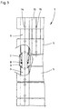
- Fig. 1 shows a side sectional view of a radiator assembly.
- a radiator 1 is fixed to a wall 2 in a conventional manner, for example by means of a traverse 3 and bolt 4.
- the radiator comprises in the normal installation position horizontally extending heating tubes 5, which are usually supplied at the end of the flow with leading heating medium - hot water - and flows through it. Most often, the water passes to the other end or, using appropriate separation guides or the like, at the same end into a return pipe. Roughly indicated this is in Fig. 2 , where hot water enters the heating tubes 5 via openings 14 of the feed 11, which are then flowed through. The water then passes through holes 15 in a return header 13.
- the heating tubes can be round, flat, lamellar, etc.
- Fig. 1 shows that the radiator is equipped with a collector 6, which is fluidly connected via bores with the heating tubes 5.
- This collector 6 opens at the lower end in a socket 7, which is connected via a sealing package 8 with a sleeve 9. While the sleeve 9 is a fixed element, the entire heater 1, which is rotationally connected to the bushing 7, waterproof in the sleeve 9 are rotated. The rotation takes place about the vertical axis M in the exemplary embodiment shown.
- Fig. 2 shows the details of such an arrangement, wherein an on-site supply connection 11 as a dip tube concentrically through the arrangement of sleeve 7 and sleeve 9 and through the openings 14 introduce the water in the lamellar heating tubes 5.
- the return water introduced into the return header 13 and guided back down.
- the return water can be transferred to the collector 6 of the arrangement, for which purpose, for example, a path of the heating tube 5 in the connection region 16 can be used.
- the return water is then passed through the path 17 in the area between the flow pipe 11 and bush 7 in the return 12.
- the bottom-side assembly 10 is rotatably connected to the sleeve 9, so that the entire heater 1 by the rotatability of the sleeve 7 relative to the sleeve 9 is rotatable.
- FIG. 3 An alternative embodiment is in Fig. 3 shown. The difference from the described embodiments is that at the lower end of the sleeve 9, another radiator segment is followed by heating pipes 5. So it is the above the sleeve 9 connected to the sleeve 7 segment relative to the lower, connected to the sleeve 9 segment rotatable.
Landscapes
- Engineering & Computer Science (AREA)
- Physics & Mathematics (AREA)
- Thermal Sciences (AREA)
- Chemical & Material Sciences (AREA)
- Combustion & Propulsion (AREA)
- Mechanical Engineering (AREA)
- General Engineering & Computer Science (AREA)
- Instantaneous Water Boilers, Portable Hot-Water Supply Apparatuses, And Control Of Portable Hot-Water Supply Apparatuses (AREA)
- Domestic Hot-Water Supply Systems And Details Of Heating Systems (AREA)
Description
- Die vorliegende Erfindung betrifft einen Heizkörper gemäß Oberbegriff des Anspruchs 1.
- Dem Stand der Technik ist es seit Jahren bekannt, Heizkörper - sowohl als funktionale Elemente zum Heizen, aber auch aus designtechnischen Gründen - mit in einer bestimmungsgemäßen Einbauposition im wesentlichen vertikal verlaufenden, meist parallelen Vorlauf- und Rücklaufrohren auszubilden, welche mit dazu winklig bzw. quer liegenden Heizrohren strömungstechnisch verbunden sind. Über das Vorlaufrohr eingebrachtes vorlaufendes Heizmedium - meist Warmwasser - wird dann durch das Heizrohr geführt und gelangt in das Rücklaufrohr.
- Es ist bekannt, dass diese Vorlauf- und Rücklaufrohre in der Regel am unteren Ende des Heizkörpers parallel vorstehen. Es ist offensichtlich, dass, wenn Vorlauf- und Rücklaufrohr mit entsprechenden bauseitigen Vorlauf- und Rücklaufanschlüssen verbunden der Heizkörper in seiner Position starr ist.
- Aus dem Stand der Technik sind ferner Heizkörper bekannt geworden, die um, eine Vertikalachse verdrehbar sind. Einen solchen Heizkörper gemäß dem Oberbegriff des Anspruchs 1 offenbart beispielsweise die
DE 295 19 417 U1 , wobei hier zur verdrehbaren Anordnung des Heizkörpers an einer Wand Anschlussstücke zum Einsatz kommen. Diese Anschlussstücke verfügen jeweils über ein mit einem Kugelkopf ausgerüstetes Kernstück, das unter Zwischenordnung von Dichtelementen zwischen einem feststehenden Gehäuseteil einerseits und einem Schraubteil andererseits eingespannt ist. Diese Konstruktion erweist sich insofern als nachteilig, als dass der Heizkörper mit seinem Gewicht auf den den Kugelkopf des Kernstücks umgebenden Dichtelementen ruht. - Ausgehend vom vorbeschriebenen Stand der Technik liegt der vorliegenden Erfindung die Aufgabe zugrunde, einen Heizkörper der gattungsgemäßen Art dahingehend weiterzubilden, dass der Heizkörper ganz oder teilweise um eine Vertikalachse drehbar ist, und dies bei gleichzeitiger Betriebssicherheit.
- Die Drehbarkeit von Heizkörpern hat unterschiedliche Vorteile. Im Badbereich bei beengten Verhältnissen kann der Heizkörper je nach Nutzungsart positioniert werden. Auch aus hygienischen Gründen zur Förderung einer allseitigen Reinigung oder für die Verwendung als Badtuchwärmer ist die Drehbarkeit des Heizkörpers wünschenswert.
- Zur technischen Lösung der Aufgabe wird mit der Erfindung ein Heizkörper mit den Merkmalen des Anspruches 1 vorgeschlagen. Weitere Vorteile und Merkmale ergeben sich aus den Unteransprüchen.
- Der erfindungsgemäße Heizkörper umfasst ein Kollektorrohr, welches zum einen von einem dem Vorlauf oder dem Rücklauf des Heizungssystems dienenden Rohr durchragt wird, zum anderen strömungstechnisch mit den jeweils anderen Vor- beziehungsweise Rücklauf verbunden ist. Auf diese Weise werden in einem Rohr sowohl Vorlauf als auch Rücklauf geführt. Das Rohr ist in Axialrichtung wenigstens einmal geteilt, so dass die beiden sich ergebenden Rohrstücke wasserdicht aber gegeneinander verdrehbar miteinander verbunden sind. Auf diese Weise kann also das Kollektorrohr drehbar gestaltet sein. Wenn das Innenrohr konzentrisch angeordnet ist, ergibt sich somit eine Verdrehbarkeit um 360° der beiden axial aneinander angeordneten Rohrstücke gegeneinander. Wird das eine am Heizkörper und das andere am bauseitigen Anschluss befestigt, wobei das Innenrohr durchgehend ausgebildet sein kann oder ebenfalls axial geteilt, so ergeben sich ein innerer wasserdichter durchgehend durchströmbarer Bereich im Innenrohr und ein im Übrigen durch das Kollektorrohr selbst wasserdichter strömungstechnisch durchgehender Bereich. Auf diese Weise können Vorlauf und Rücklauf trotz Verdrehbarkeit durchgehend geführt werden.
- Gemäß einem weiteren vorteilhaften Vorschlag der Erfindung ist der Vorlauf als Tauchrohr ausgebildet, der das gesamte Kollektorrohr vollständig durchragt und in den Heizkörper hineinragt. Gemäß einem weiteren alternativen Vorschlag ist in das Vorlaufrohr ein elektrisch betriebener Heizstab eingesetzt. Auf diese Weise können auch elektrisch betriebene Heizkörper verdrehbar ausgestaltet werden. Das Vorlauf-Tauchrohr kann aus Metall oder Kunststoff gebildet sein.
- Gemäß einem besonders vorteilhaften Vorschlag der Erfindung wird die Verbindung zwischen Rücklauf und Kollektorrohr über wenigstens ein Heizrohr gebildet. Auf diese Weise werden zusätzliche Verbindungsleitungen verzichtbar. In vorteilhafter Weise kann das Kollektorrohr mit dem innenliegenden als Tauchrohr gebildeten Innenrohr über die volle Höhe des Heizkörpers ausgebildet sein. Dies gibt die Möglichkeit, mehr als eine Heizrohr-Verbindung zwischen Rücklauf und Kollektorrohr herzustellen. Gemäß einem weiteren vorteilhaften Vorschlag der Erfindung können auch Heizkörpersegmente mit entsprechenden Kollektorrohranordnungen ausgebildet sein. In diesem Fall besteht die Möglichkeit, die Heizkörper segmentweise aneinanderzusetzen. Die Segmente sind dann relativ zueinander verdrehbar. Dies hat beispielsweise Vorteile im Einsatz im Badbereich, wo der Heizkörper auch als Handtuchwärmer, Trockner oder dergleichen verwendbar ist.
- Gemäß einem vorteilhaften Vorschlag der Erfindung ist das Kollektorrohr aus Metall gebildet. Aber auch Kunststoffe, isolierte Rohrleitungen liegen im Rahmen der Erfindung. Auch kann das Kollektorrohr wasserdicht mit einem Innenrohr versehen sein, in welches wiederum durchragend das Vorlauf- beziehungsweise Rücklaufrohr eingesetzt ist.
- Mit der Erfindung wird eine konstruktive Möglichkeit der Ausbildung einer Heizkörperanschlussbaugruppe bereitgestellt, welche mit überschaubarem wirtschaftlichen Aufwand herstellbar ist und die Verdrehbarkeit von Segmenten relativ zueinander und/oder ganze Heizkörper gegenüber dem bauseitigem Anschluss ermöglicht. Dies ist in beengten Verhältnissen, im Badbereich oder aus designtechnischen Gründen von Vorteil und wünschenswert. Weitere Vorteile der Erfindung ergeben sich aus der folgenden Beschreibung anhand der Figuren:
-
Fig. 1 eine Schnittdarstellung von der Seite einer Heizkörperanschlussgruppe; -
Fig. 2 eine frontale, teilgeschnittene Darstellung gemäßFig. 1 mit Ergänzung und -
Fig. 3 eine alternative Ausführungsform der Erfindung. - In den Figuren sind gleiche Elemente mit gleichen Bezugszeichen versehen.
-
Fig. 1 zeigt eine seitliche Schnittdarstellung einer Heizkörperanordnung. - Ein Heizkörper 1 ist an einer Wand 2 in herkömmlicher Weise beispielsweise mittels einer Traverse 3 und Bolzen 4 befestigt. Der Heizkörper umfasst in bestimmungsgemäßer Einbaulage horizontal verlaufende Heizrohre 5, die in der Regel endseitig vom Vorlauf mit vorlaufendem Heizmedium - heißem Wasser - beliefert und von diesem durchströmt werden. Meistens gelangt das Wasser an das andere Ende oder unter Verwendung von entsprechenden Trennführungen oder dergleichen am selben Ende in ein Rücklaufrohr. Grob angedeutet ist dies in
Fig. 2 , wo über Öffnungen 14 des Vorlaufs 11 heißes Wasser in die Heizrohre 5 gelangt, die dann durchströmt werden. Das Wasser gelangt dann über Bohrungen 15 in einen Rücklaufsammler 13. Die Heizrohre können rund, flach, lamellenartig usw. sein. - Das Beispiel in
Fig. 1 zeigt, dass der Heizkörper mit einem Sammler 6 bestückt ist, der über Bohrungen mit den Heizrohren 5 strömungstechnisch verbunden ist. Dieser Sammler 6 mündet am unteren Ende in eine Buchse 7, die über ein Dichtungspaket 8 mit einer Hülse 9 verbunden ist. Während die Hülse 9 ein feststehendes Element ist, kann der gesamte Heizkörper 1, der verdrehfest mit der Buchse 7 verbunden ist, wasserdicht in der Hülse 9 verdreht werden. Die Drehung erfolgt um die im gezeigten Ausführungsbeispiel vertikale Mittelachse M. -
Fig. 2 zeigt die Details einer solchen Anordnung, wobei ein bauseitiger Vorlaufanschluss 11 als Tauchrohr konzentrisch die Anordnung von Buchse 7 und Hülse 9 durchragt und über die Öffnungen 14 das Wasser in die lamellenartig ausgebildeten Heizrohre 5 einbringen. Nachdem die Heizrohre durchströmt sind, wird über die Bohrungen 15 das Rücklaufwasser in den Rücklaufsammler 13 eingebracht und wieder nach unten geführt. Im Bereich des untersten Segmentes wiederum kann das Rücklaufwasser in den Sammler 6 der Anordnung überführt werden, wozu beispielsweise ein Weg des Heizrohres 5 im Verbindungsbereich 16 verwendet werden kann. Das Rücklaufwasser wird dann über den Weg 17 in den Bereich zwischen Vorlaufrohr 11 und Buchse 7 in den Rücklauf 12 geführt. Die bodenseitige Baugruppe 10 ist drehfest mit der Hülse 9 verbunden, so dass der gesamte Heizkörper 1 durch die Verdrehbarkeit der Buchse 7 gegenüber der Hülse 9 verdrehbar ist. - Ein alternatives Ausführungsbeispiel ist in
Fig. 3 gezeigt. Der Unterschied zu den beschriebenen Ausführungsbeispielen besteht darin, dass sich am unteren Ende der Hülse 9 ein weiteres Heizkörpersegment mit Heizrohren 5 anschließt. Es ist also das oberhalb der Hülse 9 mit der Buchse 7 verbundene Segment gegenüber dem unteren, mit der Hülse 9 verbundenen Segment drehbar. - Die beschriebenen Ausführungsbeispiele dienen nur der Erläuterung und sind nicht beschränkend.
-
- 1
- Heizkörper
- 2
- Wand
- 3
- Traverse
- 4
- Bolzen
- 5
- Heizrohr
- 6
- Sammler
- 7
- Buchse
- 8
- Dichtungspaket
- 9
- Hülse
- 10
- Baugruppe
- 11
- Vorlauf
- 12
- Rücklauf
- 13
- Rücklaufsammler
- 14
- Verbindungsbohrungen
- 15
- Verbindungsbohrungen
- 16
- Verbindungsbereich
- 17
- Weg
- 20
- Heizstab
- M
- Mittellinie
Claims (8)
- Heizkörperanordnung mit einem Vorlaufrohr (11) und einem Rücklaufrohr (12), welche mit dazu winklig angeordneten Heizrohren (5) verbunden sind, und mit einem Kollektorrohr, welches strömungstechnisch mit dem Rücklaufrohr (12) verbunden ist und welches von dem Vorlaufrohr (11) durchragt wird, das konzentrisch im Kollektorrohr angeordnet ist und wobei das Kollektorrohr in Axialrichtung in einen Sammler (6), eine Buchse (7) und eine Hülse (9) geteilt ist, wobei der Sammler (6) verdrehfest mit der Buchse (7) verbunden ist, wobei die Buchse (7) und die Hülse (9) gegeneinander verdrehbar aber wasserdicht miteinander verbunden sind, zu welchem Zweck die Buchse (7) über ein Dichtungspaket (8) mit der Hülse (9) verbunden ist, dadurch gekennzeichnet, dass der Sammler (6) in die Buchse (7) mündet, und dass die Buchse (7) randseitig einen Vorsprung aufweist, der radial in einen nach oben offenen Absatz am oberen Ende der Hülse (9) ragt.
- Heizkörperanordnung nach Anspruch 1, dadurch gekennzeichnet, dass die strömungstechnische Verbindung mit dem Kollektorrohr über wenigstens ein Heizrohr hergestellt ist.
- Heizkörperanordnung nach Anspruch 1 oder 2, dadurch gekennzeichnet, dass ein Teil des Kollektorrohrs mit einem bauseitigen Vorlauf-/Rücklaufanschluss verbunden ist.
- Heizkörperanordnung nach einem der vorhergehenden Ansprüche, dadurch gekennzeichnet, dass das Vorlaufrohr als Tauchrohr in dem Kollektorrohr geführt wird.
- Heizkörperanordnung nach einem der vorhergehenden Ansprüche, dadurch gekennzeichnet, dass in das Vorlaufrohr ein elektrischer Heizstab eingebracht ist.
- Heizkörperahordnung nach einem der vorhergehenden Ansprüche, dadurch gekennzeichnet, dass über das Kollektorrohr Heizkörpersegmente miteinander verbunden sind.
- Heizkörperanordnung nach einem der vorhergehenden Ansprüche, dadurch gekennzeichnet, dass das Kollektorrohr aus Metall gebildet ist.
- Heizkörperanordnung nach Anspruch 4, dadurch gekennzeichnet, dass das Vorlauf-Tauchrohr aus Metall oder Kunststoff besteht.
Priority Applications (2)
| Application Number | Priority Date | Filing Date | Title |
|---|---|---|---|
| PL10007644T PL2410247T3 (pl) | 2010-07-23 | 2010-07-23 | Obrotowe przyłącze grzejnika |
| EP10007644.7A EP2410247B1 (de) | 2010-07-23 | 2010-07-23 | Drehbarer Heizkörperanschluss |
Applications Claiming Priority (1)
| Application Number | Priority Date | Filing Date | Title |
|---|---|---|---|
| EP10007644.7A EP2410247B1 (de) | 2010-07-23 | 2010-07-23 | Drehbarer Heizkörperanschluss |
Publications (2)
| Publication Number | Publication Date |
|---|---|
| EP2410247A1 EP2410247A1 (de) | 2012-01-25 |
| EP2410247B1 true EP2410247B1 (de) | 2016-02-17 |
Family
ID=42651242
Family Applications (1)
| Application Number | Title | Priority Date | Filing Date |
|---|---|---|---|
| EP10007644.7A Active EP2410247B1 (de) | 2010-07-23 | 2010-07-23 | Drehbarer Heizkörperanschluss |
Country Status (2)
| Country | Link |
|---|---|
| EP (1) | EP2410247B1 (de) |
| PL (1) | PL2410247T3 (de) |
Family Cites Families (3)
| Publication number | Priority date | Publication date | Assignee | Title |
|---|---|---|---|---|
| DE9213964U1 (de) * | 1992-10-16 | 1992-12-10 | Klostermann, Harald, 5750 Menden | Handtuchtrockner |
| AT404405B (de) * | 1994-12-07 | 1998-11-25 | Vogel & Noot Waermetechnik Ag | Heizkörper mit im wesentlichen rohrartiger zuführung und abführung für ein wärmeträgerfluid |
| DE202007009383U1 (de) * | 2007-07-02 | 2007-09-06 | Kalor Thermotechnik Gmbh | Heizkörper |
-
2010
- 2010-07-23 PL PL10007644T patent/PL2410247T3/pl unknown
- 2010-07-23 EP EP10007644.7A patent/EP2410247B1/de active Active
Also Published As
| Publication number | Publication date |
|---|---|
| EP2410247A1 (de) | 2012-01-25 |
| PL2410247T3 (pl) | 2016-08-31 |
Similar Documents
| Publication | Publication Date | Title |
|---|---|---|
| EP2458298A2 (de) | Elektrischer Wassererwärmer | |
| EP2890849B1 (de) | Gleitstuhl für eine schienenweiche | |
| DE102005018560A1 (de) | Rohrverbindung | |
| DE102014001818A1 (de) | Anschlussstück für einen Auslauf einer Sanitärarmatur | |
| EP1161645A1 (de) | Heiz-(kühl-)körper | |
| EP3141666A1 (de) | Wasserarmatur, insbesondere für einen wohnwagen, caravan, motorcaravan oder ein boot | |
| EP1672286B1 (de) | Verteilervorrichtung für einen mit einem flüssigen Medium betriebenen Kreislauf einer Wärmeversorgungsanlage | |
| EP3168375B1 (de) | Wandarmatur | |
| EP3012553B1 (de) | Baueinheit für eine Heizungsanlage | |
| EP2410247A1 (de) | Drehbarer Heizkörperanschluss | |
| DE202009001030U1 (de) | Trink- oder Brauchwassersystem | |
| DE102005002627A1 (de) | Duscheinrichtung | |
| DE102014218994B3 (de) | Stromschienensystem | |
| EP3511634B1 (de) | Anschluss-set | |
| DE202009013707U1 (de) | Zugdeichsel für einen Anhänger | |
| DE202009013093U1 (de) | Gabelbaum für ein Segelbrett | |
| EP2294340B1 (de) | Warmwassergerät | |
| AT501301B1 (de) | Heizkörper | |
| EP3812677B1 (de) | Radiator zur kühlung eines transformators oder einer drosselspule | |
| AT412503B (de) | Verteilergruppe für plattenheizkörper | |
| DE102005007182B3 (de) | Heizkörper | |
| DE202009017485U1 (de) | Soleverteiler für Erdwärmesonden | |
| EP2444757B1 (de) | Heizkörper mit einer Anschlussbaugruppe | |
| EP1371916B1 (de) | Heizkörperanschlussvorrichtung | |
| AT501107B1 (de) | Thermische solaranlage |
Legal Events
| Date | Code | Title | Description |
|---|---|---|---|
| AK | Designated contracting states |
Kind code of ref document: A1 Designated state(s): AL AT BE BG CH CY CZ DE DK EE ES FI FR GB GR HR HU IE IS IT LI LT LU LV MC MK MT NL NO PL PT RO SE SI SK SM TR |
|
| AX | Request for extension of the european patent |
Extension state: BA ME RS |
|
| PUAI | Public reference made under article 153(3) epc to a published international application that has entered the european phase |
Free format text: ORIGINAL CODE: 0009012 |
|
| 17P | Request for examination filed |
Effective date: 20120302 |
|
| 17Q | First examination report despatched |
Effective date: 20120531 |
|
| RAP1 | Party data changed (applicant data changed or rights of an application transferred) |
Owner name: ZEHNDER GROUP INTERNATIONAL AG |
|
| REG | Reference to a national code |
Ref country code: DE Ref legal event code: R079 Ref document number: 502010011057 Country of ref document: DE Free format text: PREVIOUS MAIN CLASS: F24D0013040000 Ipc: F24D0019000000 |
|
| RIC1 | Information provided on ipc code assigned before grant |
Ipc: F24D 19/00 20060101AFI20151001BHEP Ipc: F24D 19/02 20060101ALI20151001BHEP Ipc: F24D 13/04 20060101ALI20151001BHEP |
|
| GRAP | Despatch of communication of intention to grant a patent |
Free format text: ORIGINAL CODE: EPIDOSNIGR1 |
|
| INTG | Intention to grant announced |
Effective date: 20151110 |
|
| GRAS | Grant fee paid |
Free format text: ORIGINAL CODE: EPIDOSNIGR3 |
|
| GRAA | (expected) grant |
Free format text: ORIGINAL CODE: 0009210 |
|
| AK | Designated contracting states |
Kind code of ref document: B1 Designated state(s): AL AT BE BG CH CY CZ DE DK EE ES FI FR GB GR HR HU IE IS IT LI LT LU LV MC MK MT NL NO PL PT RO SE SI SK SM TR |
|
| REG | Reference to a national code |
Ref country code: GB Ref legal event code: FG4D Free format text: NOT ENGLISH |
|
| REG | Reference to a national code |
Ref country code: CH Ref legal event code: NV Representative=s name: E. BLUM AND CO. AG PATENT- UND MARKENANWAELTE , CH Ref country code: CH Ref legal event code: EP |
|
| REG | Reference to a national code |
Ref country code: IE Ref legal event code: FG4D Free format text: LANGUAGE OF EP DOCUMENT: GERMAN |
|
| REG | Reference to a national code |
Ref country code: AT Ref legal event code: REF Ref document number: 775836 Country of ref document: AT Kind code of ref document: T Effective date: 20160315 |
|
| REG | Reference to a national code |
Ref country code: DE Ref legal event code: R096 Ref document number: 502010011057 Country of ref document: DE |
|
| REG | Reference to a national code |
Ref country code: NL Ref legal event code: MP Effective date: 20160217 |
|
| REG | Reference to a national code |
Ref country code: LT Ref legal event code: MG4D |
|
| REG | Reference to a national code |
Ref country code: FR Ref legal event code: PLFP Year of fee payment: 7 |
|
| PG25 | Lapsed in a contracting state [announced via postgrant information from national office to epo] |
Ref country code: FI Free format text: LAPSE BECAUSE OF FAILURE TO SUBMIT A TRANSLATION OF THE DESCRIPTION OR TO PAY THE FEE WITHIN THE PRESCRIBED TIME-LIMIT Effective date: 20160217 Ref country code: IT Free format text: LAPSE BECAUSE OF FAILURE TO SUBMIT A TRANSLATION OF THE DESCRIPTION OR TO PAY THE FEE WITHIN THE PRESCRIBED TIME-LIMIT Effective date: 20160217 Ref country code: GR Free format text: LAPSE BECAUSE OF FAILURE TO SUBMIT A TRANSLATION OF THE DESCRIPTION OR TO PAY THE FEE WITHIN THE PRESCRIBED TIME-LIMIT Effective date: 20160518 Ref country code: ES Free format text: LAPSE BECAUSE OF FAILURE TO SUBMIT A TRANSLATION OF THE DESCRIPTION OR TO PAY THE FEE WITHIN THE PRESCRIBED TIME-LIMIT Effective date: 20160217 Ref country code: NO Free format text: LAPSE BECAUSE OF FAILURE TO SUBMIT A TRANSLATION OF THE DESCRIPTION OR TO PAY THE FEE WITHIN THE PRESCRIBED TIME-LIMIT Effective date: 20160517 |
|
| PG25 | Lapsed in a contracting state [announced via postgrant information from national office to epo] |
Ref country code: SE Free format text: LAPSE BECAUSE OF FAILURE TO SUBMIT A TRANSLATION OF THE DESCRIPTION OR TO PAY THE FEE WITHIN THE PRESCRIBED TIME-LIMIT Effective date: 20160217 Ref country code: PT Free format text: LAPSE BECAUSE OF FAILURE TO SUBMIT A TRANSLATION OF THE DESCRIPTION OR TO PAY THE FEE WITHIN THE PRESCRIBED TIME-LIMIT Effective date: 20160617 Ref country code: LV Free format text: LAPSE BECAUSE OF FAILURE TO SUBMIT A TRANSLATION OF THE DESCRIPTION OR TO PAY THE FEE WITHIN THE PRESCRIBED TIME-LIMIT Effective date: 20160217 Ref country code: LT Free format text: LAPSE BECAUSE OF FAILURE TO SUBMIT A TRANSLATION OF THE DESCRIPTION OR TO PAY THE FEE WITHIN THE PRESCRIBED TIME-LIMIT Effective date: 20160217 Ref country code: NL Free format text: LAPSE BECAUSE OF FAILURE TO SUBMIT A TRANSLATION OF THE DESCRIPTION OR TO PAY THE FEE WITHIN THE PRESCRIBED TIME-LIMIT Effective date: 20160217 |
|
| PG25 | Lapsed in a contracting state [announced via postgrant information from national office to epo] |
Ref country code: EE Free format text: LAPSE BECAUSE OF FAILURE TO SUBMIT A TRANSLATION OF THE DESCRIPTION OR TO PAY THE FEE WITHIN THE PRESCRIBED TIME-LIMIT Effective date: 20160217 Ref country code: DK Free format text: LAPSE BECAUSE OF FAILURE TO SUBMIT A TRANSLATION OF THE DESCRIPTION OR TO PAY THE FEE WITHIN THE PRESCRIBED TIME-LIMIT Effective date: 20160217 |
|
| REG | Reference to a national code |
Ref country code: DE Ref legal event code: R097 Ref document number: 502010011057 Country of ref document: DE |
|
| PG25 | Lapsed in a contracting state [announced via postgrant information from national office to epo] |
Ref country code: SK Free format text: LAPSE BECAUSE OF FAILURE TO SUBMIT A TRANSLATION OF THE DESCRIPTION OR TO PAY THE FEE WITHIN THE PRESCRIBED TIME-LIMIT Effective date: 20160217 Ref country code: RO Free format text: LAPSE BECAUSE OF FAILURE TO SUBMIT A TRANSLATION OF THE DESCRIPTION OR TO PAY THE FEE WITHIN THE PRESCRIBED TIME-LIMIT Effective date: 20160217 Ref country code: SM Free format text: LAPSE BECAUSE OF FAILURE TO SUBMIT A TRANSLATION OF THE DESCRIPTION OR TO PAY THE FEE WITHIN THE PRESCRIBED TIME-LIMIT Effective date: 20160217 Ref country code: CZ Free format text: LAPSE BECAUSE OF FAILURE TO SUBMIT A TRANSLATION OF THE DESCRIPTION OR TO PAY THE FEE WITHIN THE PRESCRIBED TIME-LIMIT Effective date: 20160217 |
|
| PLBE | No opposition filed within time limit |
Free format text: ORIGINAL CODE: 0009261 |
|
| STAA | Information on the status of an ep patent application or granted ep patent |
Free format text: STATUS: NO OPPOSITION FILED WITHIN TIME LIMIT |
|
| PG25 | Lapsed in a contracting state [announced via postgrant information from national office to epo] |
Ref country code: BE Free format text: LAPSE BECAUSE OF NON-PAYMENT OF DUE FEES Effective date: 20160731 |
|
| 26N | No opposition filed |
Effective date: 20161118 |
|
| PG25 | Lapsed in a contracting state [announced via postgrant information from national office to epo] |
Ref country code: BG Free format text: LAPSE BECAUSE OF FAILURE TO SUBMIT A TRANSLATION OF THE DESCRIPTION OR TO PAY THE FEE WITHIN THE PRESCRIBED TIME-LIMIT Effective date: 20160517 Ref country code: SI Free format text: LAPSE BECAUSE OF FAILURE TO SUBMIT A TRANSLATION OF THE DESCRIPTION OR TO PAY THE FEE WITHIN THE PRESCRIBED TIME-LIMIT Effective date: 20160217 |
|
| PG25 | Lapsed in a contracting state [announced via postgrant information from national office to epo] |
Ref country code: MC Free format text: LAPSE BECAUSE OF FAILURE TO SUBMIT A TRANSLATION OF THE DESCRIPTION OR TO PAY THE FEE WITHIN THE PRESCRIBED TIME-LIMIT Effective date: 20160217 |
|
| REG | Reference to a national code |
Ref country code: FR Ref legal event code: PLFP Year of fee payment: 8 |
|
| PGFP | Annual fee paid to national office [announced via postgrant information from national office to epo] |
Ref country code: IE Payment date: 20170526 Year of fee payment: 8 |
|
| PG25 | Lapsed in a contracting state [announced via postgrant information from national office to epo] |
Ref country code: LU Free format text: LAPSE BECAUSE OF NON-PAYMENT OF DUE FEES Effective date: 20160723 |
|
| REG | Reference to a national code |
Ref country code: AT Ref legal event code: MM01 Ref document number: 775836 Country of ref document: AT Kind code of ref document: T Effective date: 20160723 |
|
| PG25 | Lapsed in a contracting state [announced via postgrant information from national office to epo] |
Ref country code: AT Free format text: LAPSE BECAUSE OF NON-PAYMENT OF DUE FEES Effective date: 20160723 |
|
| REG | Reference to a national code |
Ref country code: DE Ref legal event code: R082 Ref document number: 502010011057 Country of ref document: DE Representative=s name: BRINKMANN & PARTNER PATENTANWAELTE PARTNERSCHA, DE Ref country code: DE Ref legal event code: R082 Ref document number: 502010011057 Country of ref document: DE Representative=s name: RAUSCH WANISCHECK-BERGMANN BRINKMANN PARTNERSC, DE |
|
| PG25 | Lapsed in a contracting state [announced via postgrant information from national office to epo] |
Ref country code: CY Free format text: LAPSE BECAUSE OF FAILURE TO SUBMIT A TRANSLATION OF THE DESCRIPTION OR TO PAY THE FEE WITHIN THE PRESCRIBED TIME-LIMIT Effective date: 20160217 Ref country code: HU Free format text: LAPSE BECAUSE OF FAILURE TO SUBMIT A TRANSLATION OF THE DESCRIPTION OR TO PAY THE FEE WITHIN THE PRESCRIBED TIME-LIMIT; INVALID AB INITIO Effective date: 20100723 |
|
| PG25 | Lapsed in a contracting state [announced via postgrant information from national office to epo] |
Ref country code: MK Free format text: LAPSE BECAUSE OF FAILURE TO SUBMIT A TRANSLATION OF THE DESCRIPTION OR TO PAY THE FEE WITHIN THE PRESCRIBED TIME-LIMIT Effective date: 20160217 Ref country code: MT Free format text: LAPSE BECAUSE OF FAILURE TO SUBMIT A TRANSLATION OF THE DESCRIPTION OR TO PAY THE FEE WITHIN THE PRESCRIBED TIME-LIMIT Effective date: 20160217 Ref country code: IS Free format text: LAPSE BECAUSE OF FAILURE TO SUBMIT A TRANSLATION OF THE DESCRIPTION OR TO PAY THE FEE WITHIN THE PRESCRIBED TIME-LIMIT Effective date: 20160217 Ref country code: HR Free format text: LAPSE BECAUSE OF FAILURE TO SUBMIT A TRANSLATION OF THE DESCRIPTION OR TO PAY THE FEE WITHIN THE PRESCRIBED TIME-LIMIT Effective date: 20160217 |
|
| REG | Reference to a national code |
Ref country code: FR Ref legal event code: PLFP Year of fee payment: 9 |
|
| PG25 | Lapsed in a contracting state [announced via postgrant information from national office to epo] |
Ref country code: AL Free format text: LAPSE BECAUSE OF FAILURE TO SUBMIT A TRANSLATION OF THE DESCRIPTION OR TO PAY THE FEE WITHIN THE PRESCRIBED TIME-LIMIT Effective date: 20160217 |
|
| REG | Reference to a national code |
Ref country code: IE Ref legal event code: MM4A |
|
| PG25 | Lapsed in a contracting state [announced via postgrant information from national office to epo] |
Ref country code: IE Free format text: LAPSE BECAUSE OF NON-PAYMENT OF DUE FEES Effective date: 20180723 |
|
| P01 | Opt-out of the competence of the unified patent court (upc) registered |
Effective date: 20230418 |
|
| PGFP | Annual fee paid to national office [announced via postgrant information from national office to epo] |
Ref country code: DE Payment date: 20250722 Year of fee payment: 16 |
|
| PGFP | Annual fee paid to national office [announced via postgrant information from national office to epo] |
Ref country code: TR Payment date: 20250716 Year of fee payment: 16 Ref country code: PL Payment date: 20250710 Year of fee payment: 16 |
|
| PGFP | Annual fee paid to national office [announced via postgrant information from national office to epo] |
Ref country code: GB Payment date: 20250722 Year of fee payment: 16 |
|
| PGFP | Annual fee paid to national office [announced via postgrant information from national office to epo] |
Ref country code: FR Payment date: 20250725 Year of fee payment: 16 |
|
| PGFP | Annual fee paid to national office [announced via postgrant information from national office to epo] |
Ref country code: CH Payment date: 20250801 Year of fee payment: 16 |