EP2410222A1 - Vorrichtung zum Befestigen und Abdichten einer durch eine Wandöffnung einer Gebäudewand führenden Leitung - Google Patents
Vorrichtung zum Befestigen und Abdichten einer durch eine Wandöffnung einer Gebäudewand führenden Leitung Download PDFInfo
- Publication number
- EP2410222A1 EP2410222A1 EP10015701A EP10015701A EP2410222A1 EP 2410222 A1 EP2410222 A1 EP 2410222A1 EP 10015701 A EP10015701 A EP 10015701A EP 10015701 A EP10015701 A EP 10015701A EP 2410222 A1 EP2410222 A1 EP 2410222A1
- Authority
- EP
- European Patent Office
- Prior art keywords
- wall
- holes
- conduit
- sealing
- hollow body
- Prior art date
- Legal status (The legal status is an assumption and is not a legal conclusion. Google has not performed a legal analysis and makes no representation as to the accuracy of the status listed.)
- Granted
Links
- 238000007789 sealing Methods 0.000 title claims description 19
- 239000000126 substance Substances 0.000 claims abstract description 16
- 239000000463 material Substances 0.000 claims description 9
- 230000009969 flowable effect Effects 0.000 claims description 6
- 229920005830 Polyurethane Foam Polymers 0.000 claims description 2
- 239000011796 hollow space material Substances 0.000 abstract 1
- 239000000945 filler Substances 0.000 description 6
- 239000011324 bead Substances 0.000 description 4
- 244000089486 Phragmites australis subsp australis Species 0.000 description 2
- 206010041953 Staring Diseases 0.000 description 2
- 238000006243 chemical reaction Methods 0.000 description 2
- XLYOFNOQVPJJNP-UHFFFAOYSA-N water Substances O XLYOFNOQVPJJNP-UHFFFAOYSA-N 0.000 description 2
- 239000012530 fluid Substances 0.000 description 1
- 238000009434 installation Methods 0.000 description 1
- 239000007788 liquid Substances 0.000 description 1
- 239000002184 metal Substances 0.000 description 1
- 239000004570 mortar (masonry) Substances 0.000 description 1
- 230000035515 penetration Effects 0.000 description 1
- 229920003023 plastic Polymers 0.000 description 1
Images

Classifications
-
- F—MECHANICAL ENGINEERING; LIGHTING; HEATING; WEAPONS; BLASTING
- F16—ENGINEERING ELEMENTS AND UNITS; GENERAL MEASURES FOR PRODUCING AND MAINTAINING EFFECTIVE FUNCTIONING OF MACHINES OR INSTALLATIONS; THERMAL INSULATION IN GENERAL
- F16L—PIPES; JOINTS OR FITTINGS FOR PIPES; SUPPORTS FOR PIPES, CABLES OR PROTECTIVE TUBING; MEANS FOR THERMAL INSULATION IN GENERAL
- F16L5/00—Devices for use where pipes, cables or protective tubing pass through walls or partitions
- F16L5/02—Sealing
-
- H—ELECTRICITY
- H02—GENERATION; CONVERSION OR DISTRIBUTION OF ELECTRIC POWER
- H02G—INSTALLATION OF ELECTRIC CABLES OR LINES, OR OF COMBINED OPTICAL AND ELECTRIC CABLES OR LINES
- H02G3/00—Installations of electric cables or lines or protective tubing therefor in or on buildings, equivalent structures or vehicles
- H02G3/22—Installations of cables or lines through walls, floors or ceilings, e.g. into buildings
Definitions
- the invention relates to a device for fastening and sealing a leading through a wall opening of a building wall line, with a line within the wall opening at a radial distance surrounding the hollow body, which is connected at both lateral ends by end pieces with the line and a cavity for receiving a first flowable, then hardening filling substance limited.
- conduit is to be understood in a broad sense, which may be either a conduit for receiving a portion of at least one power cable, a water pipe, a gas pipe or a telecommunication line, or such a conduit itself.
- cables and pipes are inserted into a building, they must be mechanically fixed in the passage opening of the building wall provided for this purpose, and the space between the pipe and the wall must be sealed against the passage of water and if possible also gas.
- a device of the aforementioned type in which a sleeve made of a flexible material surrounds the conduit, which forms a volume for receiving an initially flowable, expanding filling substance together with end-side end pieces.
- the filled filler increases its volume by a chemical reaction and builds up a pressure for expansion of the sleeve, through which the sleeve is pressed against the wall of the wall duct. As a result, the sleeve is pressed in the wall opening, so that it is fixed by friction and / or positive fit in the wall opening.
- the present invention has for its object to provide a device of the type considered, which is suitable for wall penetrations of all commonly occurring diameter and reliably provides for walls with trapped cavities for a high-grade seal.
- the invention provides that as a hollow body, which surrounds the line with a radial distance, a rigid tube is used, the wall of which has a plurality of circumferentially distributed, small holes, which are preferably uniformly spaced in the circumferential direction, so that the filling substance emerges substantially uniformly on all sides and fills the space between the pipe and the wall.
- the diameter of the holes is matched to the filler used, whereby the amount of leaking filler can be controlled.
- a two-component expansion material such as a two-component PU foam is advantageously used.
- the material remains fluid for about one minute and passes as a result of the small holes on all sides largely uniformly, upwards, sideways and downwards, which prevents a large part of the substance escapes downwards and in cavities in the lower area the wall opening seeped.
- the invention is not limited to the use of a material which can be expanded by a chemical reaction, but it is also possible to introduce an initially liquid and then hardening filling substance which does not expand through a pump or press or through a manually operated filling device.
- the line is fixed in this way by the leaked out of the rigid tube, hardened filler in the wall duct.
- the substance can fill in the open holes to the core hole in the wall by sufficient filling substance is introduced into the rigid tube, so that even in the case of masonry walls, which may also consist of hollow blocks, a reliable attachment and sealing is caused.
- the rigid tube can be firmly connected to the attached thereto end pieces with the line, for example, be glued to this, or be pushed into a clamping fit on this.
- the rigid tube may conveniently have a diameter of about 30-50 millimeters, preferably 36 millimeters.
- a material for the tube is for example a rigid plastic such as ABS or a metal into consideration.
- the duct is a conduit through which one or more cables or eg a pipe is inserted into the building after installation
- a sealing plug which engages the wall duct and with an annular sealing bead outside the wall is sealed, and attached to the inside of the building to a clamping device, which with a sealing disc the wall opening closes and grips the empty tube and transmits such a tensile force on the conduit by tightening a nut that the sealing bead surrounding the wall bore of the sealing plug is pressed firmly against the wall.
- a sealing plug and the associated clamping device are in the DE 10 2008 027 901 A1 disclosed, the disclosure of which is included here.
- At least one end piece preferably facing the building exterior, has holes, so that the filling substance can fill the cavity in the wall bore up to the sealing bead.
- the other end piece has holes, the entire cavity can be filled up to the inner sealing disc.
- the outlet of the filling substance can be controlled in terms of time and quantity by suitable selection of the hole size of the rigid tube and of the filling material.
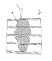
- a wall of hollow blocks 1 includes a passage opening 2, passes through the center of a designated above as a conduit empty tube 3, which at the Building exterior 4 is attached to a sealing plug 5. There is a sealing bead 21 between the sealing plug 5 and the outside of the wall.
- the empty tube 3 is gripped by a clamping device 6 on the opposite inside of the building, an additional sealing disc 8 being arranged between the saving device 6 and the inner wall 7.
- a tube 13 coming from the inside of the building leads into the cavity 10, which passes through the sealing disc 8 in advance. Through this tube 13, an initially flowable, then hardening filling substance is introduced into the cavity 10.
- the rigid tube 9 includes a plurality of small holes 14 which are equally spaced from each other in the circumferential direction and in the longitudinal direction and thereby have a small distance of a few millimeters from each other.
- areas In the in FIG. 4 indicated by the reference numeral 17a areas have the holes 18 in the circumferential direction a smaller distance from each other. In these areas are webs 19 of hollow blocks, so that here exits a larger amount of filler and the webs 19 includes.
- the expanded and hardened filling substance which has leaked uniformly in all directions from the holes 14, partially fills the cavities 15 of the hollow blocks both above. as well as below the device according to the invention up to a line 16 in Fig. 1A , A similar filling of the cavities shows Fig. 2 as a result of an experiment with the device according to the invention.
Landscapes
- Engineering & Computer Science (AREA)
- General Engineering & Computer Science (AREA)
- Architecture (AREA)
- Civil Engineering (AREA)
- Structural Engineering (AREA)
- Mechanical Engineering (AREA)
- Installation Of Indoor Wiring (AREA)
- Building Environments (AREA)
Abstract
Description
- Vorrichtung zum Befestigen und Abdichten einer durch eine Wandöffnung einer Gebäudewand führenden Leitung
- Die Erfindung betrifft eine Vorrichtung zum Befestigen und Abdichten einer durch eine Wandöffnung einer Gebäudewand führenden Leitung, mit einem die Leitung innerhalb der Wandöffnung mit radialem Abstand umgebenden Hohlkörper, der an beiden seitlichen Enden durch Abschlussstücke mit der Leitung verbunden ist und einen Hohlraum zur Aufnahme einer zunächst fließfähigen, dann erhärtenden Füllsubstanz begrenzt.
- Der Begriff "Leitung" ist im weiten Sinne zu verstehend, wobei es sich entweder um ein Leerrohr zur Aufnahme eines Abschnitts wenigstens eines Stromkabels, eines Wasserrohres, eines Gasrohres oder einer Telekommunikationsleitung handeln kann oder um eine derartige Leitung selbst.
- Wenn Kabel und Rohre in ein Gebäude eingeführt werden, müssen sie in der hierzu vorgesehenen Durchlassöffnung der Gebäudewand mechanisch befestigt werden, und der Zwischenraum zwischen der Leitung und der Wand muss gegen den Durchtritt von Wasser und möglichst auch Gas abgedichtet werden. Hierzu ist es seit langem bekannt, die Durchlassöffnung mit einem Mörtel auszufüllen oder insbesondere bei mit Hohlräumen versehenen Wänden eine Expansionssubstanz einzubringen, die zunächst fließfähig ist und später erhärtet. Dies hat sich nicht bewährt, da das Expansionsmaterial im fließfähigen Zustand in die unteren Hohlräume der Wanddurchführung unkontrolliert eindringt, wo ein großer Teil des Materials praktisch verloren geht, während es nicht in die oberen Bereiche der Durchlassöffnung gelangt.
- Aus der
DE 20 2007 018 490 U1 ist eine Vorrichtung der eingangs genannten Art bekannt, bei der eine aus einem flexiblen Material bestehende Hülse die Leitung umgibt, die zusammen mit endseitigen Abschlussstücken ein Volumen zur Aufnahme einer zunächst fließfähigen, expandierenden Füllsubstanz bildet. Die eingefüllte Füllsubstanz vergrößert durch eine chemische Reaktion ihr Volumen und baut dabei einen Druck zur Expansion der Hülse auf, durch den die Hülse an die Wand der Mauerdurchführung angepresst wird. Hierdurch wird die Hülse in der Maueröffnung verpresst, so dass sie durch Haftreibung und/oder Formschluss in der Maueröffnung fixiert ist. - Der vorliegenden Erfindung liegt die Aufgabe zugrunde, eine Vorrichtung der betrachteten Art anzugeben, die für Mauerdurchführungen aller üblicherweise auftretenden Durchmesser geeignet ist und auch bei Wänden mit eingeschlossenen Hohlräumen zuverlässig für eine hochgradige Abdichtung sorgt.
- Diese Aufgabe wird erfindungsgemäß durch die Merkmale des Patentanspruchs 1 gelöst.
- Vorteilhafte Ausgestaltungen der Erfindungen sind in den Unteransprüchen gekennzeichnet.
- Die Erfindung sieht vor, dass als Hohlkörper, der die Leitung mit radialem Abstand umgibt, ein starres Rohr verwendet wird, dessen Wand eine Vielzahl von über den Umfang verteilten, kleinen Löchern aufweist, die in Umfangsrichtung vorzugsweise gleichmäßig voneinander beabstandet sind, so dass die Füllsubstanz im wesentlichen gleichmäßig nach allen Seiten austritt und den Zwischenraum zwischen dem Rohr und der Wand ausfüllt. Dabei ist der Durchmesser der Löcher auf die verwendete Füllsubstanz abgestimmt, wodurch die Menge der austretenden Füllsubstanz gesteuert werden kann.
- Als Füllsubstanz wird mit Vorteil ein Zweikomponenten-Expansionsmaterial wie ein Zwei-Komponenten PU-Schaum verwendet. Das Material bleibt etwa eine Minute lang flüssig und tritt dabei in Folge der klein bemessen Löcher nach allen Seiten weitestgehend gleichmäßig aus, nach oben, seitlich und nach unten, wodurch verhindert ist, dass ein Großteil der Substanz nach unten austritt und in Hohlräumen im unteren Bereich der Wandöffnung versickert.
- Dabei ist die Erfindung nicht auf die Verwendung eines durch chemische Reaktion expandierbaren Materials beschränkt, sondern es kann auch eine zunächst flüssige und sich dann erhärtende Füllsubstanz, die nicht expandiert, durch eine Pumpe oder Presse oder durch eine manuell betätigte Befüllvorrichtung eingebracht werden.
- Die Leitung wird auf diese Weise durch die aus dem starren Rohr ausgetretene, erhärtete Füllsubstanz in der Wanddurchführung fixiert. Außerdem kann die Substanz die zu der Kernlochbohrung offenen Hohlräume in der Wand ausfüllen, indem genügend Füllsubstanz in das starre Rohr eingeführt wird, so dass auch im Fall gemauerter Wände, die auch aus Hohlblocksteinen bestehen können, eine zuverlässige Befestigung und Abdichtung hervorgerufen wird.
- Das starre Rohr kann mit den daran befestigten Abschlussstücken fest mit der Leitung verbunden, beispielsweise an dieser angeklebt sein, oder aber in einem Klemmsitz auf diese aufgeschoben sein. Das starre Rohr kann zweckmäßigerweise einen Durchmesser von etwa 30 - 50 Millimeter, vorzugsweise 36 Millimeter haben. Als Material für das Rohr kommt beispielsweise ein starrer Kunststoff wie ABS oder auch ein Metall in Betracht.
- Wenn die Leitung ein Leerrohr ist, durch das nach seinem Einbau ein oder mehrere Kabel oder z.B. ein Rohr in das Gebäude eingeführt wird, ist dieses vorteilhafterweise an der Gebäudeaussenseite an einem Dichtstopfen, der in die Wanddurchführung eingreift und mit einer ringförmigen Dichtungswulst außen gegenüber der Wand abgedichtet ist, und an der Gebäudeinnenseite an einer Spannvorrichtung befestigt, die mit einer Dichtscheibe die Maueröffnung verschließt und das Leerrohr ergreift und durch Anziehen einer Mutter eine solche Zugkraft auf das Leerrohr überträgt, dass die die Wandbohrung umgebende Dichtungswulst des Dichtstopfens fest an die Wand angepresst wird. Ein derartiger Dichtstopfen und die zugehörige Spannvorrichtung sind in der
DE 10 2008 027 901 A1 offenbart, deren Offenbarungsgehalt hier eingeschlossen wird. - Mit Vorteil kann vorgesehen sein, dass wenigstens ein Abschluss-Stück, vorzugsweise das der Gebäudeaußenseite zugewandte, Löcher aufweist, so dass die Füllsubstanz den Hohlraum in der Wandbohrung bis zu der Dichtungswulst ausfüllen kann. Wenn auch das andere Abschluss-Stück Löcher aufweist, kann auch der gesamte Hohlraum bis zur inneren Dichtscheibe ausgefüllt werden.
- Bei der erfindungsgemäßen Vorrichtung ist der Austritt der Füllsubstanz durch geeignete Auswahl der Lochgröße des starren Rohres und des Füllmaterials zeitlich und mengenmäßig steuerbar.
- Weitere Einzelheiten der Erfindung ergeben sich aus der nachfolgenden Beschreibung einer bevorzugten Ausführungsform sowie anhand der Zeichnungen. Dabei zeigen:
- Fig. 1 A und 1 B
- einen Längsschnitt und eine perspektivische Ansicht einer durch eine Wand aus Hohlblocksteinen führenden erfindungsgemäßen Vorrichtung;
- Fig. 2
- einen Längsschnitt durch eine Wand, deren Durchlassöffnung mit der erfindungsgemäßen Vorrichtung mit Füllsubstanz gefüllt ist;
- Fig. 3A und 3B
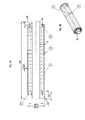
- einen Längsschnitt und eine perspektivische Ansicht eines auf einer Leitung befestigten starren Rohres;
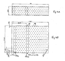
- Fig. 4A und 4B
- eine Seitenansicht und eine Abwicklung eines starren Rohres.
- Eine Wand aus Hohlblocksteinen 1 enthält eine Durchführungsöffnung 2, durch die mittig ein oben als Leitung bezeichnetes Leerrohr 3 hindurchführt, das an der Gebäudeaußenseite 4 an einem Dichtstopfen 5 befestigt ist. Zwischen dem Dichtstopfen 5 und der Außenseite der Wand befindet sich eine Dichtungswulst 21. An der gegenüberliegenden Gebäudeinnenseite ist das Leerrohr 3 von einer Spannvorrichtung 6 ergriffen, wobei zwischen der Sparinvorrichtung 6 und der Innenwand 7 eine zusätzliche Dichtscheibe 8 angeordnet ist.
- Auf dem Leerrohr 3 ist ein starres Rohr 9 größeren Durchmessers befestigt, wobei der so entstehende Hohlraum 10 durch ringförmige seitliche Abschlussstücke 11, 12 verschlossen ist, die an den Rohren befestigt sind. Die Abschlussstücke haben Durchgangslöcher 17.
- Durch das Abschlussstück 12 führt ein von der Gebäudeinnenseite her kommender Schlauch 13 in den Hohlraum 10, der zuvor durch die Dichtscheibe 8 hindurchführt. Durch diesen Schlauch 13 wird eine zunächst fließfähige, dann erhärtende Füllsubstanz in den Hohlraum 10 eingeführt.
- Das starre Rohr 9 enthält eine Vielzahl kleiner Löcher 14, die jeweils in Umfangsrichtung und in Längsrichtung gleichmäßig voneinander beabstandet sind und dabei einen kleinen Abstand von wenigen Millimetern voneinander haben. In den in
Figur 4 mit dem Bezugszeichen 17a angedeuteten Bereichen haben die Löcher 18 in Umfangsrichtung einen kleineren Abstand voneinander. In diesen Bereichen befinden sich Stege 19 von Hohlblocksteinen, so dass hier eine größere Menge Füllsubstanz austritt und die Stege 19 umfasst. - Die expandierte und erhärtete Füllsubstanz, die gleichmäßig nach allen Richtungen aus den Löchern 14 ausgetreten ist, füllt teilweise die Hohlräume 15 der Hohlblocksteine sowohl oberhalb. als auch unterhalb der erfindungsgemäßen Vorrichtung bis zu einer Linie 16 in
Fig. 1A . Eine ähnliche Verfüllung der Hohlräume zeigtFig. 2 als Ergebnis eines Versuchs mit der erfindungsgemäßen Vorrichtung. - Es wird betont, dass die Erfindung nicht auf die beschriebenen und dargestellten Ausführungsformen beschränkt ist. Vielmehr sind alle offenbarten Merkmale auf jede sinnvolle Weise einzeln miteinander kombinierbar.
Claims (8)
- Vorrichtung zum Befestigen und Abdichten einer durch eine Wandöffnung (2) einer Gebäudewand (1) führenden Leitung (3), mit einem die Leitung (3) innerhalb der Wandöffnung mit radialem Abstand umgebenden Hohlkörper (9), der an beiden seitlichen Enden durch Abschlussstücke (11,12) mit der Leitung (3) fest verbunden ist und einen Hohlraum (10) zur Aufnahme einer zunächst fließfähigen, dann erhärtenden Füllsubstanz begrenzt,
dadurch gekennzeichnet,
dass der Hohlkörper ein starres Rohr (9) ist, dessen Wand eine Vielzahl von über den Umfang verteilten, kleinen Löchern (14, 18) aufweist. - Vorrichtung nach Anspruch 1,
dadurch gekennzeichnet,
dass die Löcher (14,18) in Umfangsrichtung jeweils gleichmäßig voneinander beabstandet sind. - Vorrichtung nach Anspruch 1 oder 2,
dadurch gekennzeichnet,
dass die Abschlussstücke (11,12) fest mit dem Rohr (9) und mit der Leitung (3) verbunden sind oder in einem Klemmsitz auf diese aufgeschoben sind. - Vorrichtung nach einem der Ansprüche 1 bis 3,
dadurch gekennzeichnet,
dass wenigstens ein Abschluss-Stück (11,12) Löcher (17) aufweist. - Vorrichtung nach Anspruch 1
dadurch gekennzeichnet,
dass die Füllsubstanz ein Zweikomponenten-Expansionsmaterial wie ein Zwei-Komponenten PU-Schaum ist. - Vorrichtung nach einem der Ansprüche 1 bis 5,
dadurch gekennzeichnet,
dass die Löcher (14, 18) einen Durchmesser von 1 - 2 Millimeter, vorzugsweise von 1,5 Millimeter haben. - Vorrichtung nach einem der Ansprüche 1 bis 6,
dadurch gekennzeichnet,
dass das starre Rohr (9) einen Durchmesser von 30 - 50 Millimeter, vorzugsweise von 36 Millimeter hat. - Vorrichtung nach einem der Ansprüche 1 bis 7,
dadurch gekennzeichnet,
dass die Leitung (3) ein Leerrohr ist, das an der Aussenseite der Gebäudewand von einem Dichtstopfen (5) und an der Innenseite der Gebäudewand von einer Spannvorrichtung (6) gehalten ist.
Applications Claiming Priority (1)
| Application Number | Priority Date | Filing Date | Title |
|---|---|---|---|
| DE102010031877 | 2010-07-21 |
Publications (2)
| Publication Number | Publication Date |
|---|---|
| EP2410222A1 true EP2410222A1 (de) | 2012-01-25 |
| EP2410222B1 EP2410222B1 (de) | 2012-11-07 |
Family
ID=44081181
Family Applications (1)
| Application Number | Title | Priority Date | Filing Date |
|---|---|---|---|
| EP10015701A Active EP2410222B1 (de) | 2010-07-21 | 2010-12-16 | Vorrichtung zum Befestigen und Abdichten einer durch eine Wandöffnung einer Gebäudewand führenden Leitung |
Country Status (1)
| Country | Link |
|---|---|
| EP (1) | EP2410222B1 (de) |
Cited By (8)
| Publication number | Priority date | Publication date | Assignee | Title |
|---|---|---|---|---|
| DE202012002751U1 (de) | 2012-03-16 | 2013-06-18 | Doyma Gmbh & Co | LWL-Hauseinführung |
| EP3217057A3 (de) * | 2016-03-07 | 2017-10-25 | gabo Systemtechnik GmbH | Vorrichtung und verfahren zum befestigen und abdichten einer leitungsdurchführung in einem wanddurchgang einer gebäudewand |
| EP3624284A1 (de) | 2018-09-14 | 2020-03-18 | Langmatz GmbH | Vorrichtung zum durchführen einer speedpipe durch eine wandbohrung |
| EP3719945A1 (de) | 2019-04-05 | 2020-10-07 | Langmatz GmbH | Vorrichtung zum durchführen wenigstens einer leitung durch eine wandbohrung |
| EP3719553A1 (de) | 2019-04-05 | 2020-10-07 | Langmatz GmbH | Vorrichtung zum durchführen wenigstens einer leitung durch eine wandbohrung |
| EP3806254A1 (de) | 2019-10-09 | 2021-04-14 | Langmatz GmbH | Vorrichtung zum durchführen einer leitung, insbesondere einer speedpipe durch eine wandbohrung |
| DE102019133788A1 (de) * | 2019-12-10 | 2021-06-10 | Langmatz Gmbh | Vorrichtung zum Durchführen wenigstens eines Glasfaser-Kabels durch eine Wandbohrung |
| DE102020117975A1 (de) | 2020-07-08 | 2022-01-13 | Langmatz Gmbh | Vorrichtung zum Durchführen einer Leitung oder einer Speedpipe durch eine Wandbohrung |
Citations (4)
| Publication number | Priority date | Publication date | Assignee | Title |
|---|---|---|---|---|
| DE4131147C1 (de) * | 1991-09-19 | 1992-11-19 | Werner 7925 Dischingen De Hauff | |
| EP0681134A1 (de) * | 1994-05-07 | 1995-11-08 | Werner Hauff | Vorrichtung zur Durchführung von Leitungen durch eine Wandöffnung |
| DE202007018490U1 (de) | 2007-12-14 | 2009-04-16 | Hauff-Technik Gmbh & Co. Kg | Leitungsdurchführung durch eine Gebäudewand |
| DE102008027901A1 (de) | 2008-06-11 | 2009-12-24 | Lic Langmatz Gmbh | Anordnung zum Durchführen eines Glasfaserleiters durch eine Gebäudewand |
-
2010
- 2010-12-16 EP EP10015701A patent/EP2410222B1/de active Active
Patent Citations (4)
| Publication number | Priority date | Publication date | Assignee | Title |
|---|---|---|---|---|
| DE4131147C1 (de) * | 1991-09-19 | 1992-11-19 | Werner 7925 Dischingen De Hauff | |
| EP0681134A1 (de) * | 1994-05-07 | 1995-11-08 | Werner Hauff | Vorrichtung zur Durchführung von Leitungen durch eine Wandöffnung |
| DE202007018490U1 (de) | 2007-12-14 | 2009-04-16 | Hauff-Technik Gmbh & Co. Kg | Leitungsdurchführung durch eine Gebäudewand |
| DE102008027901A1 (de) | 2008-06-11 | 2009-12-24 | Lic Langmatz Gmbh | Anordnung zum Durchführen eines Glasfaserleiters durch eine Gebäudewand |
Cited By (14)
| Publication number | Priority date | Publication date | Assignee | Title |
|---|---|---|---|---|
| DE202012002751U1 (de) | 2012-03-16 | 2013-06-18 | Doyma Gmbh & Co | LWL-Hauseinführung |
| EP3217057A3 (de) * | 2016-03-07 | 2017-10-25 | gabo Systemtechnik GmbH | Vorrichtung und verfahren zum befestigen und abdichten einer leitungsdurchführung in einem wanddurchgang einer gebäudewand |
| EP3624284A1 (de) | 2018-09-14 | 2020-03-18 | Langmatz GmbH | Vorrichtung zum durchführen einer speedpipe durch eine wandbohrung |
| DE102019108986A1 (de) * | 2019-04-05 | 2020-10-08 | Langmatz Gmbh | Vorrichtung zum Durchführen wenigstens einer Leitung durch eine Wandbohrung |
| EP3719553A1 (de) | 2019-04-05 | 2020-10-07 | Langmatz GmbH | Vorrichtung zum durchführen wenigstens einer leitung durch eine wandbohrung |
| DE102019108980A1 (de) * | 2019-04-05 | 2020-10-08 | Langmatz Gmbh | Vorrichtung zum Durchführen wenigstens einer Leitung durch eine Wandbohrung |
| EP3719945A1 (de) | 2019-04-05 | 2020-10-07 | Langmatz GmbH | Vorrichtung zum durchführen wenigstens einer leitung durch eine wandbohrung |
| EP3806254A1 (de) | 2019-10-09 | 2021-04-14 | Langmatz GmbH | Vorrichtung zum durchführen einer leitung, insbesondere einer speedpipe durch eine wandbohrung |
| DE102019127122A1 (de) * | 2019-10-09 | 2021-04-15 | Langmatz Gmbh | Vorrichtung zum Durchführen einer Leitung, insbesondere einer Speedpipe durch eine Wandbohrung |
| DE102019127122B4 (de) | 2019-10-09 | 2022-05-12 | Langmatz Gmbh | Vorrichtung zum Durchführen einer Leitung, insbesondere einer Speedpipe durch eine Wandbohrung |
| DE102019133788A1 (de) * | 2019-12-10 | 2021-06-10 | Langmatz Gmbh | Vorrichtung zum Durchführen wenigstens eines Glasfaser-Kabels durch eine Wandbohrung |
| EP3835840A1 (de) | 2019-12-10 | 2021-06-16 | Langmatz GmbH | Vorrichtung zum durchführen wenigstens eines glasfaser-kabels durch eine wandbohrung |
| DE102019133788B4 (de) * | 2019-12-10 | 2021-06-17 | Langmatz Gmbh | Vorrichtung zum Durchführen wenigstens eines Glasfaser-Kabels durch eine Wandbohrung |
| DE102020117975A1 (de) | 2020-07-08 | 2022-01-13 | Langmatz Gmbh | Vorrichtung zum Durchführen einer Leitung oder einer Speedpipe durch eine Wandbohrung |
Also Published As
| Publication number | Publication date |
|---|---|
| EP2410222B1 (de) | 2012-11-07 |
Similar Documents
| Publication | Publication Date | Title |
|---|---|---|
| EP2410222B1 (de) | Vorrichtung zum Befestigen und Abdichten einer durch eine Wandöffnung einer Gebäudewand führenden Leitung | |
| DE60001936T2 (de) | Vorrichtung zur verankerung einer kabelstruktur | |
| DE20311950U1 (de) | Korrosionsgeschütztes Zugglied, insbesondere Spannglied für Spannbeton | |
| EP3217057B1 (de) | Vorrichtung und verfahren zum befestigen und abdichten einer leitungsdurchführung in einem wanddurchgang einer gebäudewand | |
| EP0553309B1 (de) | Bohrrohr | |
| EP2113702B1 (de) | Kupplung zum Verbinden zweier Rohrenden mit sekundärer Quelldichtung | |
| EP2075404B1 (de) | Einrichtung zum Einbringen von Mörtel | |
| DE102011078561B4 (de) | Hauseinführung | |
| EP3624284B1 (de) | Vorrichtung zum durchführen einer speedpipe durch eine wandbohrung | |
| AT15972U1 (de) | Installationsblock | |
| DE3325931C1 (de) | Bohrlochverschluß für das Flach- und Tiefharzen | |
| DE102013224027B4 (de) | Durchführungsvorrichtung für Leitungen, insbesondere Hauseinführung | |
| CH711118A1 (de) | Rohrmuffe für Well- und Glattrohre. | |
| DE7827573U1 (de) | Schalldämpfer für Luftleitungen, insbesondere für Klimaanlagen | |
| EP2645507B1 (de) | Leitungsdurchführung zur Befestigung in einer Gebäudewand | |
| EP1835091A2 (de) | Distanzrohr für Spannstäbe | |
| EP3835840B1 (de) | Vorrichtung zum durchführen wenigstens eines glasfaser-kabels durch eine wandbohrung | |
| DE19715885C2 (de) | Dichteinrichtung zum dichten Durchführen mindestens einer in einem Schutzrohr angeordneten Medienleitung durch eine Wandöffnung | |
| DE102011085006A1 (de) | Vorrichtung zur Versorgung eines Gebäudes mit Wasser oder Gas | |
| EP1593895B1 (de) | Abdichtelement | |
| DE102012208736A1 (de) | Gesteinsanker | |
| DE102010010210B4 (de) | Brandschutzmanschette | |
| EP3806254B1 (de) | Vorrichtung zum durchführen einer leitung, insbesondere einer speedpipe durch eine wandbohrung | |
| DE10346463A1 (de) | System zum Durchführen wenigstens eines Kabels oder eines Leitungsrohres durch eine Gebäudewand | |
| DE20122303U1 (de) | Schutzrohrdichtungssystem für ein Wanddurchführungssystem |
Legal Events
| Date | Code | Title | Description |
|---|---|---|---|
| 17P | Request for examination filed |
Effective date: 20110712 |
|
| AK | Designated contracting states |
Kind code of ref document: A1 Designated state(s): AL AT BE BG CH CY CZ DE DK EE ES FI FR GB GR HR HU IE IS IT LI LT LU LV MC MK MT NL NO PL PT RO RS SE SI SK SM TR |
|
| AX | Request for extension of the european patent |
Extension state: BA ME |
|
| PUAI | Public reference made under article 153(3) epc to a published international application that has entered the european phase |
Free format text: ORIGINAL CODE: 0009012 |
|
| GRAP | Despatch of communication of intention to grant a patent |
Free format text: ORIGINAL CODE: EPIDOSNIGR1 |
|
| GRAS | Grant fee paid |
Free format text: ORIGINAL CODE: EPIDOSNIGR3 |
|
| GRAA | (expected) grant |
Free format text: ORIGINAL CODE: 0009210 |
|
| AK | Designated contracting states |
Kind code of ref document: B1 Designated state(s): AL AT BE BG CH CY CZ DE DK EE ES FI FR GB GR HR HU IE IS IT LI LT LU LV MC MK MT NL NO PL PT RO RS SE SI SK SM TR |
|
| REG | Reference to a national code |
Ref country code: GB Ref legal event code: FG4D Free format text: NOT ENGLISH |
|
| REG | Reference to a national code |
Ref country code: AT Ref legal event code: REF Ref document number: 583152 Country of ref document: AT Kind code of ref document: T Effective date: 20121115 Ref country code: CH Ref legal event code: NV Representative=s name: KIRKER AND CIE S.A., CH Ref country code: CH Ref legal event code: EP |
|
| REG | Reference to a national code |
Ref country code: IE Ref legal event code: FG4D Free format text: LANGUAGE OF EP DOCUMENT: GERMAN |
|
| REG | Reference to a national code |
Ref country code: DE Ref legal event code: R096 Ref document number: 502010001580 Country of ref document: DE Effective date: 20130103 |
|
| REG | Reference to a national code |
Ref country code: NL Ref legal event code: VDEP Effective date: 20121107 |
|
| REG | Reference to a national code |
Ref country code: LT Ref legal event code: MG4D |
|
| PG25 | Lapsed in a contracting state [announced via postgrant information from national office to epo] |
Ref country code: SE Free format text: LAPSE BECAUSE OF FAILURE TO SUBMIT A TRANSLATION OF THE DESCRIPTION OR TO PAY THE FEE WITHIN THE PRESCRIBED TIME-LIMIT Effective date: 20121107 Ref country code: NO Free format text: LAPSE BECAUSE OF FAILURE TO SUBMIT A TRANSLATION OF THE DESCRIPTION OR TO PAY THE FEE WITHIN THE PRESCRIBED TIME-LIMIT Effective date: 20130207 Ref country code: HR Free format text: LAPSE BECAUSE OF FAILURE TO SUBMIT A TRANSLATION OF THE DESCRIPTION OR TO PAY THE FEE WITHIN THE PRESCRIBED TIME-LIMIT Effective date: 20121107 Ref country code: LT Free format text: LAPSE BECAUSE OF FAILURE TO SUBMIT A TRANSLATION OF THE DESCRIPTION OR TO PAY THE FEE WITHIN THE PRESCRIBED TIME-LIMIT Effective date: 20121107 Ref country code: IS Free format text: LAPSE BECAUSE OF FAILURE TO SUBMIT A TRANSLATION OF THE DESCRIPTION OR TO PAY THE FEE WITHIN THE PRESCRIBED TIME-LIMIT Effective date: 20130307 Ref country code: FI Free format text: LAPSE BECAUSE OF FAILURE TO SUBMIT A TRANSLATION OF THE DESCRIPTION OR TO PAY THE FEE WITHIN THE PRESCRIBED TIME-LIMIT Effective date: 20121107 Ref country code: NL Free format text: LAPSE BECAUSE OF FAILURE TO SUBMIT A TRANSLATION OF THE DESCRIPTION OR TO PAY THE FEE WITHIN THE PRESCRIBED TIME-LIMIT Effective date: 20121107 |
|
| PG25 | Lapsed in a contracting state [announced via postgrant information from national office to epo] |
Ref country code: SI Free format text: LAPSE BECAUSE OF FAILURE TO SUBMIT A TRANSLATION OF THE DESCRIPTION OR TO PAY THE FEE WITHIN THE PRESCRIBED TIME-LIMIT Effective date: 20121107 Ref country code: LV Free format text: LAPSE BECAUSE OF FAILURE TO SUBMIT A TRANSLATION OF THE DESCRIPTION OR TO PAY THE FEE WITHIN THE PRESCRIBED TIME-LIMIT Effective date: 20121107 Ref country code: PT Free format text: LAPSE BECAUSE OF FAILURE TO SUBMIT A TRANSLATION OF THE DESCRIPTION OR TO PAY THE FEE WITHIN THE PRESCRIBED TIME-LIMIT Effective date: 20130307 Ref country code: PL Free format text: LAPSE BECAUSE OF FAILURE TO SUBMIT A TRANSLATION OF THE DESCRIPTION OR TO PAY THE FEE WITHIN THE PRESCRIBED TIME-LIMIT Effective date: 20121107 Ref country code: GR Free format text: LAPSE BECAUSE OF FAILURE TO SUBMIT A TRANSLATION OF THE DESCRIPTION OR TO PAY THE FEE WITHIN THE PRESCRIBED TIME-LIMIT Effective date: 20130208 |
|
| BERE | Be: lapsed |
Owner name: LANGMATZ G.M.B.H. Effective date: 20121231 |
|
| PG25 | Lapsed in a contracting state [announced via postgrant information from national office to epo] |
Ref country code: EE Free format text: LAPSE BECAUSE OF FAILURE TO SUBMIT A TRANSLATION OF THE DESCRIPTION OR TO PAY THE FEE WITHIN THE PRESCRIBED TIME-LIMIT Effective date: 20121107 Ref country code: CZ Free format text: LAPSE BECAUSE OF FAILURE TO SUBMIT A TRANSLATION OF THE DESCRIPTION OR TO PAY THE FEE WITHIN THE PRESCRIBED TIME-LIMIT Effective date: 20121107 Ref country code: DK Free format text: LAPSE BECAUSE OF FAILURE TO SUBMIT A TRANSLATION OF THE DESCRIPTION OR TO PAY THE FEE WITHIN THE PRESCRIBED TIME-LIMIT Effective date: 20121107 Ref country code: MC Free format text: LAPSE BECAUSE OF NON-PAYMENT OF DUE FEES Effective date: 20121231 Ref country code: RS Free format text: LAPSE BECAUSE OF FAILURE TO SUBMIT A TRANSLATION OF THE DESCRIPTION OR TO PAY THE FEE WITHIN THE PRESCRIBED TIME-LIMIT Effective date: 20121107 Ref country code: BG Free format text: LAPSE BECAUSE OF FAILURE TO SUBMIT A TRANSLATION OF THE DESCRIPTION OR TO PAY THE FEE WITHIN THE PRESCRIBED TIME-LIMIT Effective date: 20130207 Ref country code: SK Free format text: LAPSE BECAUSE OF FAILURE TO SUBMIT A TRANSLATION OF THE DESCRIPTION OR TO PAY THE FEE WITHIN THE PRESCRIBED TIME-LIMIT Effective date: 20121107 |
|
| PG25 | Lapsed in a contracting state [announced via postgrant information from national office to epo] |
Ref country code: RO Free format text: LAPSE BECAUSE OF FAILURE TO SUBMIT A TRANSLATION OF THE DESCRIPTION OR TO PAY THE FEE WITHIN THE PRESCRIBED TIME-LIMIT Effective date: 20121107 Ref country code: IT Free format text: LAPSE BECAUSE OF FAILURE TO SUBMIT A TRANSLATION OF THE DESCRIPTION OR TO PAY THE FEE WITHIN THE PRESCRIBED TIME-LIMIT Effective date: 20121107 |
|
| PLBE | No opposition filed within time limit |
Free format text: ORIGINAL CODE: 0009261 |
|
| STAA | Information on the status of an ep patent application or granted ep patent |
Free format text: STATUS: NO OPPOSITION FILED WITHIN TIME LIMIT |
|
| REG | Reference to a national code |
Ref country code: IE Ref legal event code: MM4A |
|
| REG | Reference to a national code |
Ref country code: FR Ref legal event code: ST Effective date: 20130830 |
|
| PG25 | Lapsed in a contracting state [announced via postgrant information from national office to epo] |
Ref country code: BE Free format text: LAPSE BECAUSE OF NON-PAYMENT OF DUE FEES Effective date: 20121231 |
|
| 26N | No opposition filed |
Effective date: 20130808 |
|
| PG25 | Lapsed in a contracting state [announced via postgrant information from national office to epo] |
Ref country code: IE Free format text: LAPSE BECAUSE OF NON-PAYMENT OF DUE FEES Effective date: 20121216 Ref country code: ES Free format text: LAPSE BECAUSE OF FAILURE TO SUBMIT A TRANSLATION OF THE DESCRIPTION OR TO PAY THE FEE WITHIN THE PRESCRIBED TIME-LIMIT Effective date: 20130218 |
|
| PG25 | Lapsed in a contracting state [announced via postgrant information from national office to epo] |
Ref country code: FR Free format text: LAPSE BECAUSE OF NON-PAYMENT OF DUE FEES Effective date: 20130107 Ref country code: CY Free format text: LAPSE BECAUSE OF FAILURE TO SUBMIT A TRANSLATION OF THE DESCRIPTION OR TO PAY THE FEE WITHIN THE PRESCRIBED TIME-LIMIT Effective date: 20121107 Ref country code: AL Free format text: LAPSE BECAUSE OF FAILURE TO SUBMIT A TRANSLATION OF THE DESCRIPTION OR TO PAY THE FEE WITHIN THE PRESCRIBED TIME-LIMIT Effective date: 20121107 Ref country code: MT Free format text: LAPSE BECAUSE OF FAILURE TO SUBMIT A TRANSLATION OF THE DESCRIPTION OR TO PAY THE FEE WITHIN THE PRESCRIBED TIME-LIMIT Effective date: 20121107 |
|
| REG | Reference to a national code |
Ref country code: DE Ref legal event code: R097 Ref document number: 502010001580 Country of ref document: DE Effective date: 20130808 |
|
| PG25 | Lapsed in a contracting state [announced via postgrant information from national office to epo] |
Ref country code: TR Free format text: LAPSE BECAUSE OF FAILURE TO SUBMIT A TRANSLATION OF THE DESCRIPTION OR TO PAY THE FEE WITHIN THE PRESCRIBED TIME-LIMIT Effective date: 20121107 |
|
| PG25 | Lapsed in a contracting state [announced via postgrant information from national office to epo] |
Ref country code: LU Free format text: LAPSE BECAUSE OF NON-PAYMENT OF DUE FEES Effective date: 20121216 Ref country code: SM Free format text: LAPSE BECAUSE OF FAILURE TO SUBMIT A TRANSLATION OF THE DESCRIPTION OR TO PAY THE FEE WITHIN THE PRESCRIBED TIME-LIMIT Effective date: 20121107 |
|
| PG25 | Lapsed in a contracting state [announced via postgrant information from national office to epo] |
Ref country code: HU Free format text: LAPSE BECAUSE OF FAILURE TO SUBMIT A TRANSLATION OF THE DESCRIPTION OR TO PAY THE FEE WITHIN THE PRESCRIBED TIME-LIMIT Effective date: 20101216 |
|
| PG25 | Lapsed in a contracting state [announced via postgrant information from national office to epo] |
Ref country code: MK Free format text: LAPSE BECAUSE OF FAILURE TO SUBMIT A TRANSLATION OF THE DESCRIPTION OR TO PAY THE FEE WITHIN THE PRESCRIBED TIME-LIMIT Effective date: 20121107 |
|
| GBPC | Gb: european patent ceased through non-payment of renewal fee |
Effective date: 20141216 |
|
| PG25 | Lapsed in a contracting state [announced via postgrant information from national office to epo] |
Ref country code: GB Free format text: LAPSE BECAUSE OF NON-PAYMENT OF DUE FEES Effective date: 20141216 |
|
| PGFP | Annual fee paid to national office [announced via postgrant information from national office to epo] |
Ref country code: CH Payment date: 20151229 Year of fee payment: 6 |
|
| REG | Reference to a national code |
Ref country code: CH Ref legal event code: PL |
|
| PG25 | Lapsed in a contracting state [announced via postgrant information from national office to epo] |
Ref country code: CH Free format text: LAPSE BECAUSE OF NON-PAYMENT OF DUE FEES Effective date: 20161231 Ref country code: LI Free format text: LAPSE BECAUSE OF NON-PAYMENT OF DUE FEES Effective date: 20161231 |
|
| PGFP | Annual fee paid to national office [announced via postgrant information from national office to epo] |
Ref country code: AT Payment date: 20181218 Year of fee payment: 9 |
|
| REG | Reference to a national code |
Ref country code: AT Ref legal event code: MM01 Ref document number: 583152 Country of ref document: AT Kind code of ref document: T Effective date: 20191216 |
|
| PG25 | Lapsed in a contracting state [announced via postgrant information from national office to epo] |
Ref country code: AT Free format text: LAPSE BECAUSE OF NON-PAYMENT OF DUE FEES Effective date: 20191216 |
|
| PGFP | Annual fee paid to national office [announced via postgrant information from national office to epo] |
Ref country code: DE Payment date: 20231221 Year of fee payment: 14 |