EP2410147A2 - Abgasanlage mit reaktivem Heizsystem - Google Patents
Abgasanlage mit reaktivem Heizsystem Download PDFInfo
- Publication number
- EP2410147A2 EP2410147A2 EP11173170A EP11173170A EP2410147A2 EP 2410147 A2 EP2410147 A2 EP 2410147A2 EP 11173170 A EP11173170 A EP 11173170A EP 11173170 A EP11173170 A EP 11173170A EP 2410147 A2 EP2410147 A2 EP 2410147A2
- Authority
- EP
- European Patent Office
- Prior art keywords
- component
- system component
- reaction
- stationary
- heating
- Prior art date
- Legal status (The legal status is an assumption and is not a legal conclusion. Google has not performed a legal analysis and makes no representation as to the accuracy of the status listed.)
- Withdrawn
Links
Images

Classifications
-
- F—MECHANICAL ENGINEERING; LIGHTING; HEATING; WEAPONS; BLASTING
- F01—MACHINES OR ENGINES IN GENERAL; ENGINE PLANTS IN GENERAL; STEAM ENGINES
- F01N—GAS-FLOW SILENCERS OR EXHAUST APPARATUS FOR MACHINES OR ENGINES IN GENERAL; GAS-FLOW SILENCERS OR EXHAUST APPARATUS FOR INTERNAL-COMBUSTION ENGINES
- F01N3/00—Exhaust or silencing apparatus having means for purifying, rendering innocuous, or otherwise treating exhaust
- F01N3/08—Exhaust or silencing apparatus having means for purifying, rendering innocuous, or otherwise treating exhaust for rendering innocuous
- F01N3/10—Exhaust or silencing apparatus having means for purifying, rendering innocuous, or otherwise treating exhaust for rendering innocuous by thermal or catalytic conversion of noxious components of exhaust
- F01N3/18—Exhaust or silencing apparatus having means for purifying, rendering innocuous, or otherwise treating exhaust for rendering innocuous by thermal or catalytic conversion of noxious components of exhaust characterised by methods of operation; Control
- F01N3/20—Exhaust or silencing apparatus having means for purifying, rendering innocuous, or otherwise treating exhaust for rendering innocuous by thermal or catalytic conversion of noxious components of exhaust characterised by methods of operation; Control specially adapted for catalytic conversion
- F01N3/2006—Periodically heating or cooling catalytic reactors, e.g. at cold starting or overheating
-
- F—MECHANICAL ENGINEERING; LIGHTING; HEATING; WEAPONS; BLASTING
- F24—HEATING; RANGES; VENTILATING
- F24V—COLLECTION, PRODUCTION OR USE OF HEAT NOT OTHERWISE PROVIDED FOR
- F24V30/00—Apparatus or devices using heat produced by exothermal chemical reactions other than combustion
-
- F—MECHANICAL ENGINEERING; LIGHTING; HEATING; WEAPONS; BLASTING
- F28—HEAT EXCHANGE IN GENERAL
- F28D—HEAT-EXCHANGE APPARATUS, NOT PROVIDED FOR IN ANOTHER SUBCLASS, IN WHICH THE HEAT-EXCHANGE MEDIA DO NOT COME INTO DIRECT CONTACT
- F28D20/00—Heat storage plants or apparatus in general; Regenerative heat-exchange apparatus not covered by groups F28D17/00 or F28D19/00
- F28D20/003—Heat storage plants or apparatus in general; Regenerative heat-exchange apparatus not covered by groups F28D17/00 or F28D19/00 using thermochemical reactions
-
- F—MECHANICAL ENGINEERING; LIGHTING; HEATING; WEAPONS; BLASTING
- F28—HEAT EXCHANGE IN GENERAL
- F28D—HEAT-EXCHANGE APPARATUS, NOT PROVIDED FOR IN ANOTHER SUBCLASS, IN WHICH THE HEAT-EXCHANGE MEDIA DO NOT COME INTO DIRECT CONTACT
- F28D7/00—Heat-exchange apparatus having stationary tubular conduit assemblies for both heat-exchange media, the media being in contact with different sides of a conduit wall
- F28D7/10—Heat-exchange apparatus having stationary tubular conduit assemblies for both heat-exchange media, the media being in contact with different sides of a conduit wall the conduits being arranged one within the other, e.g. concentrically
- F28D7/106—Heat-exchange apparatus having stationary tubular conduit assemblies for both heat-exchange media, the media being in contact with different sides of a conduit wall the conduits being arranged one within the other, e.g. concentrically consisting of two coaxial conduits or modules of two coaxial conduits
-
- F—MECHANICAL ENGINEERING; LIGHTING; HEATING; WEAPONS; BLASTING
- F01—MACHINES OR ENGINES IN GENERAL; ENGINE PLANTS IN GENERAL; STEAM ENGINES
- F01N—GAS-FLOW SILENCERS OR EXHAUST APPARATUS FOR MACHINES OR ENGINES IN GENERAL; GAS-FLOW SILENCERS OR EXHAUST APPARATUS FOR INTERNAL-COMBUSTION ENGINES
- F01N2240/00—Combination or association of two or more different exhaust treating devices, or of at least one such device with an auxiliary device, not covered by indexing codes F01N2230/00 or F01N2250/00, one of the devices being
- F01N2240/12—Combination or association of two or more different exhaust treating devices, or of at least one such device with an auxiliary device, not covered by indexing codes F01N2230/00 or F01N2250/00, one of the devices being a thermal reactor
-
- F—MECHANICAL ENGINEERING; LIGHTING; HEATING; WEAPONS; BLASTING
- F01—MACHINES OR ENGINES IN GENERAL; ENGINE PLANTS IN GENERAL; STEAM ENGINES
- F01N—GAS-FLOW SILENCERS OR EXHAUST APPARATUS FOR MACHINES OR ENGINES IN GENERAL; GAS-FLOW SILENCERS OR EXHAUST APPARATUS FOR INTERNAL-COMBUSTION ENGINES
- F01N2470/00—Structure or shape of exhaust gas passages, pipes or tubes
- F01N2470/24—Concentric tubes or tubes being concentric to housing, e.g. telescopically assembled
-
- F—MECHANICAL ENGINEERING; LIGHTING; HEATING; WEAPONS; BLASTING
- F28—HEAT EXCHANGE IN GENERAL
- F28F—DETAILS OF HEAT-EXCHANGE AND HEAT-TRANSFER APPARATUS, OF GENERAL APPLICATION
- F28F2225/00—Reinforcing means
-
- F—MECHANICAL ENGINEERING; LIGHTING; HEATING; WEAPONS; BLASTING
- F28—HEAT EXCHANGE IN GENERAL
- F28F—DETAILS OF HEAT-EXCHANGE AND HEAT-TRANSFER APPARATUS, OF GENERAL APPLICATION
- F28F2265/00—Safety or protection arrangements; Arrangements for preventing malfunction
- F28F2265/26—Safety or protection arrangements; Arrangements for preventing malfunction for allowing differential expansion between elements
-
- Y—GENERAL TAGGING OF NEW TECHNOLOGICAL DEVELOPMENTS; GENERAL TAGGING OF CROSS-SECTIONAL TECHNOLOGIES SPANNING OVER SEVERAL SECTIONS OF THE IPC; TECHNICAL SUBJECTS COVERED BY FORMER USPC CROSS-REFERENCE ART COLLECTIONS [XRACs] AND DIGESTS
- Y02—TECHNOLOGIES OR APPLICATIONS FOR MITIGATION OR ADAPTATION AGAINST CLIMATE CHANGE
- Y02A—TECHNOLOGIES FOR ADAPTATION TO CLIMATE CHANGE
- Y02A50/00—TECHNOLOGIES FOR ADAPTATION TO CLIMATE CHANGE in human health protection, e.g. against extreme weather
- Y02A50/20—Air quality improvement or preservation, e.g. vehicle emission control or emission reduction by using catalytic converters
-
- Y—GENERAL TAGGING OF NEW TECHNOLOGICAL DEVELOPMENTS; GENERAL TAGGING OF CROSS-SECTIONAL TECHNOLOGIES SPANNING OVER SEVERAL SECTIONS OF THE IPC; TECHNICAL SUBJECTS COVERED BY FORMER USPC CROSS-REFERENCE ART COLLECTIONS [XRACs] AND DIGESTS
- Y02—TECHNOLOGIES OR APPLICATIONS FOR MITIGATION OR ADAPTATION AGAINST CLIMATE CHANGE
- Y02E—REDUCTION OF GREENHOUSE GAS [GHG] EMISSIONS, RELATED TO ENERGY GENERATION, TRANSMISSION OR DISTRIBUTION
- Y02E60/00—Enabling technologies; Technologies with a potential or indirect contribution to GHG emissions mitigation
- Y02E60/14—Thermal energy storage
-
- Y—GENERAL TAGGING OF NEW TECHNOLOGICAL DEVELOPMENTS; GENERAL TAGGING OF CROSS-SECTIONAL TECHNOLOGIES SPANNING OVER SEVERAL SECTIONS OF THE IPC; TECHNICAL SUBJECTS COVERED BY FORMER USPC CROSS-REFERENCE ART COLLECTIONS [XRACs] AND DIGESTS
- Y02—TECHNOLOGIES OR APPLICATIONS FOR MITIGATION OR ADAPTATION AGAINST CLIMATE CHANGE
- Y02T—CLIMATE CHANGE MITIGATION TECHNOLOGIES RELATED TO TRANSPORTATION
- Y02T10/00—Road transport of goods or passengers
- Y02T10/10—Internal combustion engine [ICE] based vehicles
- Y02T10/12—Improving ICE efficiencies
Definitions
- the present invention relates to a system component of an exhaust system for an internal combustion engine, in particular of a motor vehicle.
- Another object of the invention is an exhaust system with at least one system component.
- the invention relates to the use of a reactive heating system for heating at least one such system component of such exhaust system.
- the invention relates to a method for heating at least one such system component of such an exhaust system.
- the exhaust system of an internal combustion engine usually has the ambient temperature.
- catalytic system components of the exhaust system such.
- SCR Selective Catalytic Reduction
- the catalytic system components to become catalytically active they must be heated by the hot exhaust gas flow.
- the exhaust system itself however, with its system components is a kind of thermal ballast, since the cold exhaust system cools the exhaust gas flow even with optimal insulation. As a result, the farther it is positioned toward the end of the exhaust system, the slower the temperature of the respective catalytic plant component will increase.
- the exhaust gas temperature at least temporarily lie below the working temperature range of the respective catalytic system component, so that in this case a cooling of the catalytic system component below its operating temperature range by the exhaust gas is possible.
- the exhaust emission values occurring are not tolerable and therefore z.
- an immediate heating desirable and, for example, in a low load range, an additional heating at least the catalytic system components advantageous.
- the present invention is concerned with the problem of providing an exhaust system whose system components, as well as an associated operating method and for the use of a reactive heating system, an improved or at least one alternative embodiment, in particular by a rapid heating behavior of the exhaust system and / or their , in particular catalytic, plant components distinguished.
- the invention is thus based on the general idea of equipping an exhaust system or a system component of an exhaust system for an internal combustion engine, in particular of a motor vehicle, with at least one system section or component section having a closed cavity structure, walls of the closed cavity structure enclosing a reaction space, and in the closed cavity structure to arrange at least one stationary system component of a reactive heating system.
- a reactive heating system comprises a stationary and a mobile system component which react with one another in the reaction space in an exothermic reaction with the release of heat of reaction.
- the positioning of such a cavity structure can thus be in a manifold, a charging device, a front pipe, an oxidation catalyst, a diesel particulate filter, an exhaust pipe, a HWL (urea-water solution) -Dosierer streets, a SCR (Selective Cat Reduction) catalyst, a NSK (NOX storage catalyst), a rear exhaust pipe, connecting lines, check valves or the like can be made.
- the cavity structure is formed closed and consequently is prevented by the walls of the cavity structure a mass transfer with the environment or prevented to a negligible extent.
- the walls of the cavity structure enclose a reaction space in which the system components of a reactive heating system can react with each other in an exothermic reaction.
- the cavity structure may be formed as a double-walled casing, wherein such a double-walled casing can be arranged only in partial areas of the respective system component.
- the double-walled casing does not necessarily have to surround the respective system component, not even partially closed in the circumferential direction. Thus, only a partial arrangement of such a double-walled casing is possible in the circumferential direction.
- Such a double-walled casing is preferably used in exhaust pipe sections and / or in a catalytic system component, as well as in substantially cylindrical exhaust system components. Particularly preferred are double-walled shells in walls of catalytic system components, such.
- a catalyst eg NSK or SCR, a diesel particulate filter, a HWL metering device and / or a FP system component and used in pipes and pipe sections.
- the double-walled casing can be designed in different ways. Preference is given to a supporting tube or bearing housing on the outside and / or inside of a, in particular formed from sheet metal, wall at least partially surrounded. Between the housing or pipe and the wall of the evacuable space is then formed. The inside and / or outside positioned wall is connected to the pipe or housing by welding, crimping, folding or the like so that the intermediate space is formed pressure-tight.
- the double-walled casing is thus formed by the housing or the tube together with the wall.
- the tube or housing inside and / or outside of a, in particular non-supporting, double-walled jacket may be at least partially surrounded.
- This double-walled jacket can also be connected to the pipe or housing by welding, flanging, folding or the like.
- the intermediate space between the walls of the double-walled shell is arranged and formed pressure-tight.
- the double-walled casing is formed in this case by the double-walled jacket.
- the formation of the intermediate space between two supporting housing walls and / or pipes is also conceivable, wherein the housing walls or pipes are pressure-tightly sealed to one another by welding, flanging, flanges or the like.
- the double-walled casing is formed by the housing walls and / or pipes.
- the cavity structure is formed as a container which is arranged in and / or on the respective plant component.
- the cavity structure may preferably be formed as a closed channel system.
- a channel system may be formed as a piping system or z. Ex. As a system of several closed channels inside a catalyst substrate.
- the cavity structure is formed as a gap housing, wherein the reaction space is formed in this case by the gap of the gap housing.
- a design of the cavity structure through a gap housing substantially corresponds to a double-walled construction.
- the cavity structure designed as a gap housing is preferably used in catalytic system components, in a diesel particle filter, in an SCR catalytic converter, in a HWL metering device, in a fuel processor and / or in a fuel injector.
- the piping system can be additionally provided with a heating plate which is heated by the same due to the contact with the piping system and allows a greater release of heat due to the increased surface area.
- a heating plate may be arranged in or on the outside of a system component.
- Such a heating plate is preferably used in the case of catalytic system components, a diesel particle filter, an SCR catalyst on the inside of the system component.
- an SCR mixing device such a heating plate is preferably integral with the SCR mixing device educated.
- Such a piping system with heating plate can be referred to as a reactive heating element.
- a piping system may be formed several turns having a heating register, which is preferably used in the intake tract of the internal combustion engine.
- slot-shaped cavity structures are preferably positioned in the region of the cylinder head and / or the intake tract.
- a heating coil is also preferably arranged in the air conditioning box of the heating system.
- the walls of the cavity structure and / or the heating plate are preferably formed of metal.
- metal As metallic materials, aluminum, aluminum alloys, iron, iron alloys, steel and steel alloys are particularly preferred.
- the cavity structure has stabilization structures.
- mechanically stabilizing inserts are preferably arranged within the cavity structure, such as.
- Fiber structures, open porous or closed porous foams or the like can also be used as spacer elements.
- At least one wall of the cavity structure can be formed corrugated. Due to the corrugated training a compensation of the thermal expansion is possible. As a result, at least the corrugated wall can be moved more flexible and you have more degrees of freedom in the structural design of the exhaust system.
- such a corrugated wall is used in the case of a double-walled casing.
- the reactive heating system has at least one mobile and at least one stationary system component, as well as several construction elements, such. Eg the reaction space.
- the reactive heating system operates basically due to the exothermic reaction of the at least one mobile system component with the at least one stationary reaction component in the reaction space. Due to the heat of reaction released by the exothermic reaction, such a reactive heating system can be used for heating at least one system component. For the purposes of the invention, such an exothermic reaction between the at least two system components is largely reversible.
- Such a mobile system component of the reactive heating system is in the unbound, stored state in liquid and / or gas or vapor form. In the expelled state, the mobile system component is in gas or vapor form.
- the stationary system component is arranged in the reaction space or in the cavity structure and is solid in the bound and in the unbound state.
- the stationary system component is arranged as a bed and / or structured molded body or as a monolithic molded body in the reaction space or in the cavity structure.
- at least one wall of the cavity structure is coated with the stationary system component.
- at least one spacer element of the cavity structure such.
- a fiber material, an open porous foam or the like having at least one be coated stationary system component.
- an openly porous foam is positioned which at least partially consists of the mobile system component.
- the reactive heating system has the construction elements reaction space, storage device and a connecting line fluidically connecting the reaction space with the storage device.
- At least one stationary system component is arranged in the reaction space, while the storage device serves to store the at least one unbound mobile system component.
- the connecting line Through the connecting line, the at least one mobile system component can be supplied from the storage device to the reaction space.
- a metering device can be arranged in the connecting line with which the supply of the at least one mobile system component to the reaction space can be metered or controlled.
- the metering device can be designed as a pump, as a control valve, injection device or the like.
- a check-back device is arranged in the connecting line.
- the check device such.
- a check valve positioned, which prevents a return of the mobile component from the reaction space in the storage device, at least during the addition of the mobile system component.
- a condensation cooler is arranged in the connecting line, which liquefies the gaseous or vaporous mobile system component.
- the condensation cooler is positioned in a separate connection line.
- the connecting line is preferably designed as a pipeline.
- the connecting line is made of plastic, more preferably metallic and very particularly preferably partially metallic.
- the storage device is preferably designed as a closed collecting container, which is preferably made of plastic and most preferably made of metal. In the case of metallic formation, a formation of aluminum or an aluminum alloy is particularly preferred.
- a first temperature range can be started by supplying the mobile system component from the storage device, the exothermic reaction heat-emitting reaction in the reaction space.
- the at least one mobile system component reacts with the at least one stationary system component in a chemical and / or physical reaction to form a physical or chemical compound.
- the released heat of reaction can be used for heating at least one system component of the exhaust system.
- the first temperature range is preferably below 50 ° C., more preferably below 100 ° C., and most preferably below the operating temperature range of the respective, in particular catalytic, system component.
- the first temperature range refers to the temperature of the exhaust gas and / or to the temperature of the respective system component.
- the physical or chemical compound formed due to the exothermic reaction is formed in a reversible exothermic reaction, so that within a second temperature range as a result of a decomposition reaction, the cleavage of the physical or chemical compound to the at least one mobile and at least one stationary system component succeeds.
- These Decomposition reaction also takes place in the reaction space, it is endothermic and draws the required reaction energy from the waste heat of the exhaust stream.
- the functioning of the reactive heating system can be rudimentary divided into two phases.
- a heating phase within a predetermined first temperature range the reaction space is controlled via the connecting line and optionally by the metering device which supplies at least one mobile system component.
- the mobile system component can react with the stationary system component and the heat of reaction of this exothermic reaction released thereby can be used to heat at least one system component of the exhaust system.
- the at least one mobile system component reacts with at least one stationary system component to form a chemical or physical connection.
- the exothermic reaction to the chemical or physical compound can be reversed by means of a decomposition reaction.
- the chemical or physical compound undergoes a cleavage in an endothermic reaction to the at least one mobile and at least one stationary system component.
- the at least one mobile system component is vapor and / or gaseous in this predetermined second temperature range and can be conducted via the connecting line and / or via a separate connecting line to the storage device.
- a condensation cooler is arranged in at least one of the connecting lines, with which the gaseous or vaporous mobile System component can be liquefied and stored in the liquefied state in the storage device.
- the condensation cooler can likewise be dispensed with and the gaseous mobile system component can be stored in the storage device by means of a compressor under pressure.
- the amount of mobile system component is oversized, so that with the once stored amount of mobile system component a repeated heating of at least one system component can be performed without necessarily between the heating phases a regeneration phase must take place.
- such a reactive heating system is formed regeneratively, which also stores a portion of the waste heat of the exhaust stream in the form of chemical and / or physical heat of reaction. Consequently, no heat loss occurs in such a reactive heating system at standstill of the internal combustion engine with respect to the reactive heating system.
- the amount of generated heat of reaction for heating at least one system component can advantageously be controlled by using a metering device, the amount of generated heat of reaction for heating at least one system component, so that in the case of oversized storage of the mobile system component several heating phases are performed without having to perform a regeneration between the heating phases.
- Such a reactive heating system may be formed chemically and / or physically.
- An example of a physical design of such a reactive heating system is an adsorptive-reactive heating system.
- an adsorptive-reactive heating system at least one adsorbent is used as the stationary system component, and a liquid or a gas is used as the mobile system component. The reaction taking place upon contact of the mobile system component with the stationary system component is adsorption.
- Adsorption is the superficial accumulation of gases or liquids on the surface of a solid.
- the adsorption can take place purely physically as well as partially chemically in the manner of a chemisorption.
- An example of the chemisorption is z.
- the addition of double bonds to nickel-containing catalysts is adsorption that does not necessarily have to be purely physical, but it may be proportionate or fully based on chemical laws.
- the adsorbent used is preferably zeolite, silica gel, activated carbon or activated carbon formed as a molecular sieve, and also bentonite.
- the mobile system component used is preferably water, alcohols, hydrocarbons or a mixture of these substances.
- the adsorptive-reactive system may be hydrophilic or hydrophobic.
- zeolite in particular hydrophilic, and / or silica gel is preferably used as the hydrophilic adsorbent.
- a polar mobile system component is preferably water, alcohol and a mixture of polar compounds such. For example, water, alcohols, carboxylic acids, acidic aqueous solutions, alkaline aqueous solutions, ammoniacal aqueous solutions or the like.
- hydrophobic zeolites such as, for example, dealuminized zeolites and / or activated carbon
- hydrocarbons and mixtures of nonpolar compounds are preferably used as nonpolar mobile system components.
- adsorptive-reactive heating systems are preferably used: hydrophilic zeolites with water, zeolites with alcohol and zeolites with a water-antifreeze mixture, e.g. Water-alcohol mixture.
- the adsorptive-reactive heating system is formed closed, so that a mass transfer is prevented with the environment.
- the system pressure in the cold state at a predetermined temperature of the cold state is preferably equal to the ambient pressure.
- the system pressure in the cold state at a predetermined temperature of the cold state is less than the ambient pressure.
- the predetermined cold state temperature is between -20 ° C and 50 ° C, more preferably between -10 ° C and 40 ° C, and most preferably between 0 ° C and 25 ° C.
- such a reactive heating system can be designed as a chemically reactive heating system.
- the system components chemically react with each other, forming a chemical compound due to the chemical reaction.
- the endothermic decomposition reaction of the chemical compound to the individual system components takes place at an exhaust gas temperature and / or plant component temperature of 200 ° C to 600 ° C, more preferably at 300 ° C to 500 ° C and most preferably at 400 ° C to 500 ° C.
- a chemically reactive heating system as a stationary system component is an alkaline earth oxide, such as.
- alkaline earth oxide such as.
- systems based on a hydration of water of crystallization or based on the, in particular complex, binding of carbon monoxide can preferably be used.
- a reactive heating system which comprises a stationary system component and a mobile system component.
- a reactive heating system which has at least two stationary system components and a mobile system component.
- a reactive heating system is used with at least two stationary system components made of different materials and with a mobile system component representing a mixture of several compounds.
- a differentiated temperature structure can also be generated in the respective system components or component sections.
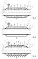
- a plant component 1 which has a cavity structure 2.
- the cavity structure 2 is formed as a double-walled casing, wherein a tubular component 3 is surrounded by a jacket 4, so that the cavity structure 2 is formed by the tubular member 3 and the jacket 4 surrounding the tubular member 3.
- a reaction space 5 is enclosed, in which a stationary system component 6 is arranged.
- the stationary system component 6 may be monolithic, as a Schippung or as a shaped body, such. Eg a fiber mat.
- a monolithic design of the stationary system component 6 is z.
- an open porous foam possible.
- arranged in the reaction chamber 5 stationary system component 6 may consist entirely of a material or the stationary system component 6 is applied to a support structure made of a different material.
- the jacket 4 is pressure-tightly connected via welds 7 to the tubular member 3 and thus the reaction chamber 5 is formed closed, so that between the reaction chamber 5 and the environment 8 no or only a negligible mass transfer is possible.
- a connecting line 9 is connected pressure-tight, in turn, with a in the Fig. 1 Not shown supply device is fluidly connected, in which the mobile system component of a reactive heating system is stored.
- the connecting line 9 is used to supply the mobile system component in the reaction chamber 5, so that when the mobile system component supply this can react with the stationary system component 6 and due to the exothermic reaction, the heat of reaction for heating the system component 1 is released.
- the connecting line 9 can be controlled with a metering device 15 or with a controllable valve device 15.
- the plant component 1, according to Fig. 2 has a stationary system component 6 as a coating on the tubular component 3.
- the released heat of reaction is advantageously generated directly on the tubular component of the system component 1.
- system component 1 has a jacket 4, which is equipped with a stabilizing structure 10.
- This stabilizing structure 10 is designed as a wave-shaped structuring of the jacket 4. Due to this elastic shaping of the shell 4, the welds 7 are less heavily burdened by a thermal expansion, since the wavy structuring can adapt to the thermal expansion more flexible than a smooth coat, such. Eg in Fig. 1 or Fig. 2 shown.
- a system component 1 which has the stationary system component 6 as a coating on the inside of the jacket 4. It is also conceivable that in addition to the in Fig. 4 shown coating of the stationary system component 6 inside the jacket 4, a coating of the stationary system component 6 is disposed on the tubular member 3. In addition, a backfilling of the reaction space 5 with a stationary system component 6 would also be conceivable.
- the plant component 1 has according to Fig. 5 a reactive heating element 11, which is arranged in the exhaust gas flow direction 12 in front of the system component 1 in a tubular member 3.
- the reactive heating element 11 has a heating plate 13, with which the heat-emitting surface can be increased, so that a heating of the system component 1 is faster.
- the reactive heating element 11 as in Fig. 6 shown, has a heating plate 13 which is connected to a piping system 14, wherein the heating plate 13 and the piping system 14 are also connected to each other with respect to a good heat conduction.
- the piping system 14 is connected to the connecting line 9 and has the stationary system component 6 inside.
- the pipeline system 14 forms the cavity structure 2, the walls of which in turn form the reaction space 5 enclose.
- Such a reactive heating element 11 may alternatively or in addition to a stationary system component 6 be used as a coating in a double-walled casing.
Landscapes
- Engineering & Computer Science (AREA)
- Chemical & Material Sciences (AREA)
- Mechanical Engineering (AREA)
- Chemical Kinetics & Catalysis (AREA)
- General Engineering & Computer Science (AREA)
- Thermal Sciences (AREA)
- Physics & Mathematics (AREA)
- Combustion & Propulsion (AREA)
- General Chemical & Material Sciences (AREA)
- Health & Medical Sciences (AREA)
- Toxicology (AREA)
- Exhaust Gas After Treatment (AREA)
- Exhaust Gas Treatment By Means Of Catalyst (AREA)
- Physical Or Chemical Processes And Apparatus (AREA)
Abstract
Description
- Die vorliegende Erfindung betrifft eine Anlagenkomponente einer Abgasanlage für eine Brennkraftmaschine, insbesondere eines Kraftfahrzeugs. Ein weiterer Gegenstand der Erfindung ist eine Abgasanlage mit zumindest einer Anlagenkomponente. Desweiteren betrifft die Erfindung die Verwendung eines reaktiven Heizsystems zur Beheizung zumindest einer solchen Anlagekomponente einer solchen Abgasanlage. Ebenso betrifft die Erfindung ein Verfahren zum Aufheizen zumindest einer solchen Anlagekomponente einer solchen Abgasanlage.
- Im Kaltstartbetrieb weist die Abgasanlage einer Brennkraftmaschine üblicherweise die Umgebungstemperatur auf. Im Temperaturbereich der Umgebungstemperatur sind jedoch katalytische Anlagenkomponenten der Abgasanlage, wie z. Bsp. ein Oxidationskatalysator oder ein Stickoxidspeicherkatalysator, sowie ein SCR(Selektive Katalytische Reduktion)-Katalysator auf einem Temperaturniveau, auf dem die jeweilige katalytische Anlagenkomponente ihre katalytische Funktion nicht oder zumindest nur in sehr eingeschränktem Umfang entfalten kann. Damit die katalytischen Anlagenkomponenten katalytisch aktiv werden, müssen dieselben durch den heißen Abgasstrom aufgeheizt werden. Die Abgasanlage selbst stellt jedoch mit ihren Anlagenkomponenten gewissermaßen einen thermischen Ballast dar, da die kalte Abgasanlage den Abgasstrom auch bei optimaler Isolierung abkühlt. Demzufolge wird die Temperatur der jeweiligen katalytischen Anlagenkomponente umso langsamer zunehmen, je weiter sie in Richtung des Endes der Abgasanlage positioniert ist.
- Zudem kann auch in niedrigen Lastbereichen der Brennkraftmaschine die Abgastemperatur zumindest zeitweise unterhalb des Arbeitstemperaturbereichs der jeweiligen katalytischen Anlagenkomponente liegen, so dass in diesem Fall eine Abkühlung der katalytischen Anlagenkomponente unterhalb ihres Arbeitstemperaturbereichs durch das Abgas möglich ist.
- Diese zuvor beispielhaft beschriebenen Problemstellungen hinsichtlich des gewünschten Arbeitstemperaturbereichs katalytischer Anlagenkomponenten können nur bedingt durch eine optimale Isolierung der Abgasanlage oder deren Ablagenkomponenten kompensiert werden.
- Aufgrund nicht wirksamer katalytischer Anlagenkomponenten sind die dabei auftretenden Abgasemissionswerte nicht tolerierbar und demzufolge ist z. Bsp. im Kaltstartbetrieb ein sofortiges Aufheizen wünschenswert und bspw. in einem niederen Lastbereich eine zusätzliche Aufheizung zumindest der katalytischen Anlagenkomponenten vorteilhaft.
- Es besteht daher ein zunehmender Bedarf an Möglichkeiten, zumindest die katalytischen Anlagenkomponenten einer Abgasanlage möglichst schnell auf Arbeitstemperatur zu bringen und/oder einen Arbeitstemperaturbereich einer katalytischen Anlagenkomponente exakt und konstant zu halten.
- Die vorliegende Erfindung beschäftigt sich dementsprechend mit dem Problem, für eine Abgasanlage deren Anlagenkomponenten, sowie für ein zugehöriges Betriebsverfahren und für die Verwendung eines reaktiven Heizsystems eine verbesserte oder zumindest eine alternative Ausführungsform anzugeben, die sich insbesondere durch ein schnelles Aufheizverhalten der Abgasanlage und/oder deren, insbesondere katalytischen, Anlagenkomponenten auszeichnet.
- Erfindungsgemäß wird dieses Problem durch die Gegenstände der unabhängigen Ansprüche gelöst. Vorteilhafte Ausführungsformen sind Gegenstand der abhängigen Ansprüche.
- Die Erfindung beruht somit auf dem allgemeinen Gedanken, eine Abgasanlage bzw. eine Anlagenkomponente einer Abgasanlage für eine Brennkraftmaschine, insbesondere eines Kraftfahrzeugs, mit zumindest einem eine geschlossene Hohlraumstruktur aufweisenden Anlagenabschnitt bzw. Komponentenabschnitt auszustatten, wobei Wände der geschlossenen Hohlraumstruktur einen Reaktionsraum umschließen, und in der geschlossenen Hohlraumstruktur zumindest eine stationäre Systemkomponente eines reaktiven Heizsystems anzuordnen.
- Dabei umfasst ein reaktives Heizsystem eine stationäre und eine mobile Systemkomponente, die in dem Reaktionsraum miteinander in einer exothermen Reaktion unter Freisetzung von Reaktionswärme reagieren.
- Aufgrund der Ausstattung der Abgasanlage bzw. zumindest einer ihrer Anlagenkomponenten mit einem reaktiven Heizsystem gelingt eine schnelle Aufheizung zumindest einer solchen, insbesondere katalytischen, Anlagenkomponente. Dadurch wird die Arbeitstemperatur bzw. der Arbeitstemperaturbereich der jeweiligen katalytischen Anlagenkomponente schnell erreicht und die Abgasemissionswerte können damit signifikant gesenkt werden.
- Dabei kann die gesamte Abgasanlage, ein Anlagenabschnitt der Abgasanlage, eine Anlagenkomponente der Abgasanlage und/oder einen Komponentenabschnitt der Anlagenkomponente mit einer derartigen zumindest eine stationäre Systemkomponente eines reaktiven Heizsystems ausgestatteten Hohlraumstruktur ausgestattet werden. Die Positionierung einer derartigen Hohlraumstruktur kann demzufolge in bzw. an einem Krümmer, einer Ladeeinrichtung, einem Vorrohr, einem Oxidations-Katalysator, einem Diesel-Partikelfilter, einem Abgasrohr, einer HWL(Harnstoff-Wasser-Lösung)-Dosiereinrichtung, einem SCR(Selektive Katalytische Reduktion)-Katalysator, einem NSK (NOX-Speicher-Katalysator), einem hinteren Abgasrohr, Verbindungsleitungen, Rückschlagventilen oder dergleichen vorgenommen werden.
- Die Hohlraumstruktur ist geschlossen ausgebildet und demzufolge ist durch die Wände der Hohlraumstruktur ein Stoffaustausch mit der Umgebung verhindert bzw. bis auf ein zu vernachlässigendes Maß unterbunden. Die Wände der Hohlraumstruktur umschließen einen Reaktionsraum, in dem die Systemkomponenten eines reaktiven Heizsystems miteinander in einer exothermen Reaktion reagieren können. Die Hohlraumstruktur kann als doppelwandige Ummantelung ausgebildet sein, wobei eine derartige doppelwandige Ummantelung nur in Teilbereichen der jeweiligen Anlagenkomponente angeordnet sein kann. Die doppelwandige Ummantelung muss dabei die jeweilige Anlagenkomponente nicht zwingend, auch nicht teilweise in Umfangsrichtung geschlossen umgeben. Somit ist auch in Umfangsrichtung eine nur teilweise Anordnung einer derartigen doppelwandigen Ummantelung möglich.
- Bevorzugt wird eine derartige doppelwandige Ummantelung bei Abgasrohrabschnitten und/oder bei einer katalytischen Anlagenkomponente, sowie bei im Wesentlichen zylindrischen Abgasanlagenkomponenten eingesetzt. Besonders bevorzugt werden doppelwandige Ummantelungen bei Wandungen katalytischer Anlagenkomponenten, wie z. Bsp. einem Katalysator, z.B. NSK oder SCR, einem Dieselpartikelfilter, einer HWL-Dosiereinrichtung und/oder einer FP-Anlagenkomponente sowie bei Rohren und Rohrabschnitten eingesetzt.
- Die doppelwandige Ummantelung kann in unterschiedlicher Art und Weise ausgebildet sein. Bevorzugt ist dabei ein tragendes Rohr oder tragendes Gehäuse außenseitig und/oder innenseitig von einer, insbesondere aus Blech ausgeformten, Wandung zumindest teilweise umgeben. Zwischen dem Gehäuse bzw. Rohr und der Wandung wird dann der evakuierbare Zwischenraum ausgebildet. Die innenseitig und/oder außenseitig positionierte Wandung ist mit dem Rohr bzw. Gehäuse durch Schweißen, Bördeln, Falzen oder dergleichen so verbunden, dass der Zwischenraum druckdicht ausgebildet ist. Die doppelwandige Ummantelung wird somit durch das Gehäuse oder das Rohr zusammen mit der Wandung ausgebildet.
- Ebenfalls bevorzugt kann das Rohr bzw. Gehäuse innen- und/oder außenseitig von einem, insbesondere nicht tragenden, doppelwandigen Mantel zumindest teilweise umgeben sein. Dieser doppelwandige Mantel kann ebenfalls mit dem Rohr bzw. Gehäuse durch Schweißen, Bördeln, Falzen oder dergleichen verbunden sein. Dabei ist der Zwischenraum zwischen den Wänden des doppelwandigen Mantels angeordnet und druckdicht ausgebildet. Die doppelwandige Ummantelung wird in diesem Fall durch den doppelwandigen Mantel ausgebildet.
- Des Weiteren ist auch die Ausbildung des Zwischenraums zwischen zwei tragenden Gehäusewandungen und/oder Rohren denkbar, wobei die Gehäusewandungen bzw. Rohre druckdicht miteinander durch Schweißen, Bördeln, Flanschen oder dergleichen verschlossen sind. In diesem Fall wird die doppelwandige Ummantelung durch die Gehäusewandungen und/oder Rohre ausgebildet.
- Ebenso bevorzugt ist die Hohlraumstruktur als ein Behälter ausgebildet, der in und/oder an der jeweiligen Anlagenkomponente angeordnet ist.
- Desweiteren kann die Hohlraumstruktur bevorzugt als ein geschlossenes Kanalsystem ausgebildet sein. Ein derartiges Kanalsystem kann als Rohrleitungssystem ausgebildet sein oder z. Bsp. als System mehrerer geschlossener Kanäle im Inneren eines Katalysatorsubstrates.
- Bevorzugt ist die Hohlraumstruktur als Spaltgehäuse ausgebildet, wobei der Reaktionsraum in diesem Fall durch den Spalt des Spaltgehäuses ausgebildet wird. Eine derartige Ausbildung der Hohlraumstruktur durch ein Spaltgehäuse entspricht im Wesentlichen einem doppelwandigen Aufbau.
- Bevorzugt wird die als Spaltgehäuse ausgebildete Hohlraumstruktur bei katalytischen Anlagenkomponenten, bei einem Diesel-Partikelfilter, bei einem SCR-Katalysator, bei einer HWL-Dosiereinrichtung, bei einem Fuelprozessor und/oder bei einem Kraftstoffinjektor verwendet.
- Im Falle der Ausbildung der Hohlraumstruktur in Art eines Rohrleitungssystems kann das Rohrleitungssystem zusätzlich mit einer Heizplatte versehen werden, die aufgrund des Kontakts mit dem Rohrleitungssystem durch dasselbe aufgeheizt wird und aufgrund der vergrößerten Oberfläche eine stärkere Abgabe von Wärme ermöglicht. Eine derartige Heizplatte kann in oder außen an einer Anlagenkomponente angeordnet sein. Bevorzugt wird eine derartige Heizplatte bei katalytischen Anlagenkomponenten, einem Dieselpartikelfilter, einem SCR-Katalysator innenseitig der Anlagenkomponente verwendet. Im Falle einer SCR-Mischeinrichtung ist eine solche Heizplatte bevorzugt integral mit der SCR-Mischeinrichtung ausgebildet. Ein solches Rohrleitungssystem mit Heizplatte kann als reaktives Heizelement bezeichnet werden.
- Ein Rohrleitungssystem kann mehrere Windungen aufweisend zu einem Heizregister ausgebildet sein, welches bevorzugt im Ansaugtrakt der Brennkraftmaschine eingesetzt ist.
- Zudem sind bevorzugt spaltförmige Hohlraumstrukturen bevorzugt im Bereich des Zylinderkopfes und/oder des Ansaugtraktes positioniert. Desweiteren ist ebenfalls bevorzugt ein Heizregister im Klimakasten des Heizungssystems angeordnet.
- Die Wände der Hohlraumstruktur und/oder die Heizplatte sind bevorzugt aus Metall ausgebildet. Als metallische Materialien sind besonders bevorzugt Aluminium, Aluminiumlegierungen, Eisen, Eisenlegierungen, Stahl und Stahllegierungen.
- Bevorzugt weist die Hohlraumstruktur Stabilisierungsstrukturen auf. So sind bevorzugt innerhalb der Hohlraumstruktur mechanisch stabilisierende Einlagen angeordnet, wie z. Bsp. gewellte Bleche, durchbrochene gewellte Bleche, Noppen, Stege oder anderweitige Distanzelemente. Es können auch Faserstrukturen, offen poröse oder geschlossen poröse Schäume oder dergleichen als Distanzelemente verwendet werden.
- Desweiteren kann zumindest eine Wand der Hohlraumstruktur gewellt ausgebildet sein. Aufgrund der gewellten Ausbildung ist ein Ausgleich der Wärmedehnung ermöglicht. Dadurch kann zumindest die gewellt ausgebildete Wand flexibler verlegt werden und man hat mehr Freiheitsgrade in der konstruktiven Gestaltung der Abgasanlage.
- Bevorzugt wird eine derartig gewellte Wand im Falle einer doppelwandigen Ummantelung verwendet.
- Das reaktive Heizsystem weist zumindest eine mobile und zumindest eine stationäre Systemkomponente auf, sowie mehrere Konstruktionselemente, wie z. Bsp. den Reaktionsraum. Das reaktive Heizsystem funktioniert grundlegend aufgrund der exothermen Reaktion der zumindest einen mobilen Systemkomponente mit der zumindest einen stationären Reaktionskomponente in dem Reaktionsraum. Aufgrund der durch die exotherme Reaktion frei werdenden Reaktionswärme kann ein derartiges reaktives Heizsystem zur Aufheizung zumindest einer Anlagenkomponente herangezogen werden. Im Sinne der Erfindung ist eine derartige exotherme Reaktion zwischen den zumindest zwei Systemkomponenten weitestgehend reversibel ausgebildet.
- Eine solche mobile Systemkomponente des reaktiven Heizsystems liegt im nicht gebundenen, bevorrateten Zustand flüssig und/oder gas- bzw. dampfförmig vor. Im ausgetriebenen Zustand liegt die mobile Systemkomponente gas- bzw. dampfförmig vor. Die stationäre Systemkomponente ist in dem Reaktionsraum bzw. in der Hohlraumstruktur angeordnet und liegt im gebundenen sowie im ungebundenen Zustand fest vor.
- Bevorzugt ist die stationäre Systemkomponente als Schüttung und/oder strukturierter Formkörper oder als monolithischer Formkörper in dem Reaktionsraum bzw. in der Hohlraumstruktur angeordnet. Besonders bevorzugt ist zumindest eine Wand der Hohlraumstruktur mit der stationären Systemkomponente beschichtet. Bevorzugt kann zusätzlich oder alternativ zumindest ein Distanzelement der Hohlraumstruktur, wie z. Bsp. ein Fasermaterial, ein offen poröser Schaum oder dergleichen mit zumindest einer stationären Systemkomponente beschichtet sein. Ganz besonders bevorzugt ist innerhalb der Hohlraumstruktur ein offen poröser Schaum positioniert, der zumindest teilweise aus der mobilen Systemskomponente besteht.
- Grundsätzlich weist das reaktive Heizsystem die Konstruktionselemente Reaktionsraum, Vorratseinrichtung und eine dem Reaktionsraum mit der Vorratseinrichtung fluidisch verbindende Verbindungsleitung auf. In dem Reaktionsraum ist zumindest eine stationäre Systemkomponente angeordnet, während die Vorratseinrichtung zur Bevorratung der zumindest einen ungebundenen mobilen Systemkomponente dient. Durch die Verbindungsleitung kann dem Reaktionsraum die zumindest eine mobile Systemkomponente aus der Vorratseinrichtung zugeführt werden. Desweiteren kann in der Verbindungsleitung eine Dosiereinrichtung angeordnet sein, mit der die Zufuhr der zumindest einen mobilen Systemkomponente zu dem Reaktionsraum dosiert bzw. gesteuert werden kann. Die Dosiereinrichtung kann als Pumpe, als Steuerventil, Injektionsvorrichtung oder dergleichen ausgebildet sein. Bevorzugt ist in der Verbindungsleitung eine Rückschlageinrichtung angeordnet. Des Weiteren ist besonders bevorzugt nach der Dosiereinrichtung und ganz besonders bevorzugt vor der Dosiereinrichtung in der Verbindungsleitung die Rückschlageinrichtung, wie z. Bsp. ein Rückschlagventil, positioniert, das einen Rücklauf der mobilen Komponente von dem Reaktionsraum in die Vorratseinrichtung zumindest während der Zugabe der mobilen Systemkomponente unterbindet.
- Bevorzugt ist in der Verbindungsleitung ein Kondensationskühler angeordnet, der die gas- bzw. dampfförmige mobile Systemkomponente verflüssigt. Besonders bevorzugt ist der Kondensationskühler in einer separaten Verbindungsleitung positioniert.
- Die Verbindungsleitung ist bevorzugt als Rohrleitung ausgebildet. Bevorzugt ist die Verbindungsleitung aus Kunststoff ausgebildet, besonders bevorzugt metallisch und ganz besonders bevorzugt bereichsweise metallisch.
- Die Vorratseinrichtung ist bevorzugt als geschlossener Sammelbehälter ausgebildet, der bevorzugt aus Kunststoff und ganz besonders bevorzugt aus Metall hergestellt ist. Im Falle der metallischen Ausbildung ist eine Ausbildung aus Aluminium oder einer Aluminiumlegierung besonders bevorzugt.
- In einem ersten Temperaturbereich kann durch Zuleitung der mobilen Systemkomponente aus der Vorratseinrichtung die exotherme Reaktionswärme abgebende Reaktion in dem Reaktionsraum gestartet werden. Dabei reagiert die zumindest eine mobile Systemkomponente mit der zumindest einen stationären Systemkomponente in einer chemischen und/oder physikalischen Reaktion zu einer physikalischen oder chemischen Verbindung. Die dabei frei werdende Reaktionswärme kann zum Aufheizen zumindest einer Anlagenkomponente der Abgasanlage herangezogen werden. Der erste Temperaturbereich ist bevorzugt unterhalb von 50°C, besonders bevorzugt unterhalb von 100°C und ganz besonders bevorzugt unterhalb des Arbeitstemperaturbereichs der jeweiligen, insbesondere katalytischen, Anlagenkomponente angeordnet. Dabei bezieht sich der erste Temperaturbereich auf die Temperatur des Abgases und/oder auf die Temperatur der jeweiligen Anlagenkomponente.
- Die aufgrund der exothermen Reaktion gebildete physikalische oder chemische Verbindung ist in einer reversiblen exothermen Reaktion gebildet, so dass innerhalb eines zweiten Temperaturbereiches infolge einer Zersetzungsreaktion die Spaltung der physikalischen bzw. chemischen Verbindung zu der zumindest einen mobilen und zumindest eine stationäre Systemkomponete gelingt. Diese Zersetzungsreaktion findet ebenfalls im Reaktionsraum statt, sie ist endotherm und bezieht die benötigte Reaktionsenergie aus der Abwärme des Abgasstroms.
- Die Funktionsweise des reaktiven Heizsystems kann rudimentär in zwei Phasen unterteilt werden. In einer Aufheizphase innerhalb eines vorbestimmten ersten Temperaturbereichs wird dem Reaktionsraum über die Verbindungsleitung und ggf. durch die Dosiereinrichtung gesteuert, die zumindest eine mobile Systemkomponente zugeführt. Dadurch kann die mobile Systemkomponente mit der stationären Systemkomponente reagieren und die dabei frei werdende Reaktionswärme dieser exothermen Reaktion zur Aufheizung zumindest einer Anlagenkomponente der Abgasanlage herangezogen werden. Dabei reagiert die zumindest eine mobile Systemkomponente mit zumindest einer stationären Systemkomponente zu einer chemischen oder physikalischen Verbindung.
- In einer Regenerierphase innerhalb eines vorbestimmten zweiten Temperaturbereichs, der üblicher Weise höher liegt als der erste Temperaturbereich kann die exotherme Reaktion zu der chemischen bzw. physikalischen Verbindung mittels einer Zersetzungsreaktion umgekehrt werden. In diesem zweiten Temperaturbereich erfährt die chemische bzw. physikalische Verbindung eine Spaltung in einer endothermen Reaktion zu der zumindest einen mobilen und zumindest einen stationären Systemkomponente. Dabei fällt in diesem vorbestimmten zweiten Temperaturbereich die zumindest eine mobile Systemkomponente dampf― und/oder gasförmig an und kann über die Verbindungsleitung und/oder über eine separate Verbindungsleitung zu der Vorratseinrichtung geleitet werden.
- Bevorzugt ist in zumindest einer der Verbindungsleitungen ein Kondensationskühler angeordnet, mit dem die gas- bzw. dampfförmige mobile Systemkomponente verflüssigt werden kann und in verflüssigtem Zustand in der Vorratseinrichtung bevorratet werden kann.
- Ohne Kondensationskühler ist es denkbar, dass die Verflüssigung der mobilen Systemskomponente in der Vorratseinrichtung selbst stattfindet, die bevorzugt gekühlt werden kann.
- Ist die mobile Systemkomponente rein gasförmig ausgebildet, so kann ebenfalls auf den Kondensationskühler verzichtet werden und die gasförmige Mobilsystemkomponente mittels eines Kompressors unter Druck in der Vorratseinrichtung bevorratet gelagert werden.
- Besonders bevorzugt ist die Menge an mobiler Systemkomponente überdimensioniert, so dass mit der einmal bevorrateten Menge an mobiler Systemkomponente eine mehrmalige Aufheizung zumindest einer Anlagenkomponente durchgeführt werden kann, ohne das zwischen den Aufheizphasen notwendigerweise eine Regenerierphase stattfinden muss.
- Vorteilhaft ist ein derartiges reaktives Heizsystem regenerativ ausgebildet, das zudem einen Teil der Abwärme des Abgasstroms in Form von chemischer und/oder physikalischer Reaktionswärme speichert. Demzufolge tritt bei einem derartigen reaktiven Heizsystem im Stillstand der Brennkraftmaschine hinsichtlich des reaktiven Heizsystems kein Wärmeverlust auf.
- Zudem kann vorteilhaft durch Verwendung einer Dosiereinrichtung die Menge an erzeugter Reaktionswärme zum Aufheizen zumindest einer Anlagenkomponente gesteuert werden, so dass im Falle einer überdimensionierten Bevorratung der mobilen Systemkomponente mehrere Aufheizphasen durchgeführt werden, ohne zwischen den Aufheizphasen eine Regenerierphase durchführen zu müssen.
- Ein derartiges reaktives Heizsystem kann chemisch und/oder physikalisch ausgebildet sein. Ein Beispiel für eine physikalische Ausbildung eines derartigen reaktiven Heizsystems ist ein adsorptiv-reaktives Heizsystem. Bei einem adsorptiv-reaktiven Heizsystem wird als stationäre Systemkomponente zumindest ein Adsorbens verwendet und als mobile Systemkomponente eine Flüssigkeit oder ein Gas. Die bei Kontakt der mobilen Systemkomponente mit der stationären Systemkomponente stattfindende Reaktion ist die Adsorption.
- Unter einer Adsorption versteht man eine oberflächliche Anreicherung von Gasen oder Flüssigkeiten an der Oberfläche eines Festkörpers. Dabei kann die Adsorption rein physikalisch als auch teilweise chemisch in Art einer Chemiesorption stattfinden. Ein Beispiel für die Chemiesorption ist z. Bsp. die Anlagerung von Doppelbindungen an nickelhaltige Katalysatoren. Somit muss die Adsorption nicht zwingend rein physikalisch verlaufen, sondern sie kann anteilig oder vollständig auf chemischen Gesetzmäßigkeiten beruhen.
- Bevorzugt wird als Adsorbens Zeolith, Silikagel, Aktivkohle oder als ein Molekularsieb ausgebildete Aktivkohle, sowie Bentonit verwendet. Als mobile Systemkomponente werden bevorzugt Wasser, Alkohole, Kohlenwasserstoffe oder ein Gemisch aus diesen Stoffen verwendet.
- Desweiteren kann das adsorptiv-reaktive System hydrophil oder hydrophob ausgebildet sein. Im Falle eines hydrophilen adsorptiv-reaktiven Heizsystems wird als hydrophiles Adsorbens bevorzugt Zeolith, insbesondere hydrophil, und/oder Silikagel verwendet. Als polare mobile Systemkomponente wird bevorzugt Wasser, Alkohol sowie ein Gemisch aus polaren Verbindungen, wie z. Bsp. Wasser, Alkoholen, Carbonsäuren, saure wässrige Lösungen, alkalisch wässrige Lösungen, ammoniakalische wässrige Lösungen oder dergleichen verwendet.
- Im Falle eines hydrophoben adsorptiv-reaktiven Systems wird bevorzugt als hydrophobes Adsorbens hydrophobe Zeolithe, wie bspw. dealluminierte Zeolithe und/oder Aktivkohle verwendet. Bevorzugt finden als unpolare mobile Systemkomponenten Kohlenwasserstoffe und Gemische aus unpolaren Verbindungen Verwendung.
- Bevorzugt werden folgende adsorptiv-reaktive Heizsysteme eingesetzt: hydrophile Zeolithe mit Wasser, Zeolithe mit Alkohol und Zeolithe mit einem Wasser-Frostschutz-Gemisch, z.B. Wasser-Alkohol-Gemisch.
- Besonders bevorzugt werden nicht brennbare Adsorbentien und/oder nicht brennbare mobile Systemkomponenten eingesetzt.
- Besonders bevorzugt ist das adsorptiv-reaktive Heizsystem geschlossen ausgebildet, so dass ein Stoffaustausch mit der Umgebung unterbunden ist. In diesem Fall ist bevorzugt der Systemdruck im kalten Zustand bei einer vorbestimmten Temperatur des kalten Zustands gleich dem Umgebungsdruck. Besonders bevorzugt ist der Systemdruck im kalten Zustand bei einer vorbestimmten Temperatur des kalten Zustands kleiner als der Umgebungsdruck. Bevorzugt ist die vorbestimmte Temperatur des kalten Zustands zwischen -20°C und 50°C, besonders bevorzugt zwischen -10°C und 40°C und ganz besonders bevorzugt zwischen 0°C und 25°C angeordnet.
- Obwohl die vorbeschriebenen Ausführungsformen eines physikalisch reaktiven Heizsystems auf der Basis von Adsorptionsvorgängen arbeiten, sind grundsätzlich auch Ausführungsformen möglich, die auf Absorptionsvorgängen beruhen oder mit einer Kombination aus Adsorption und Absorption arbeiten.
- Desweiteren kann ein derartiges reaktives Heizsystem als chemisch reaktives Heizsystem ausgebildet sein. In diesem Fall reagieren die Systemkomponenten chemisch miteinander, wobei aufgrund der chemischen Reaktion eine chemische Verbindung gebildet wird. Bevorzugt findet dabei die endotherme Zersetzungsreaktion der chemischen Verbindung zu den einzelnen Systemkomponenten bei einer Abgastemperatur und/oder Anlagenkomponententemperatur von 200°C bis 600°C statt, besonders bevorzugt bei 300°C bis 500°C und ganz besonders bevorzugt bei 400°C bis 500°C.
- Bevorzugt wird als ein derartiges chemisch reaktives Heizsystem als stationäre Systemkomponente ein Erdalkalioxid, wie z. Bsp. Kalziumoxid, Bariumoxid oder Strontiumoxid, besonders bevorzugt Kalziumoxid, verwendet und als mobile Systemkomponente Wasser.
- Als weitere chemisch reaktive Heizsysteme können Systeme basierend auf einer Kristallwasseranlagerung bzw. Kristallwassereinlagerung oder basierend auf die, insbesondere komplexe, Bindung von Kohlenmonoxid bevorzugt verwendet werden.
- Bevorzugt wird ein reaktives Heizsystem verwendet, das eine stationäre Systemkomponente und eine mobile Systemkomponente aufweist. Besonders bevorzugt wird ein reaktives Heizsystem verwendet, das zumindest zwei stationäre Systemkomponenten und eine mobile Systemkomponente aufweist. In diesem Fall ist vorteilhaft aufgrund der unterschiedlichen Reaktion der jeweiligen stationären Systemkomponente mit der mobilen Systemkomponente ein unterschiedliches Temperaturgefüge in dem jeweiligen Reaktionsraum möglich. Dadurch kann mit ein und derselben mobilen Systemkomponente ein unterschiedliches Aufheizverhalten in den jeweiligen Anlagenkomponenten bzw. Komponentenabschnitten erzeugt werden.
- Ganz besonders bevorzugt wird ein reaktives Heizsystem mit zumindest zwei aus unterschiedlichen Materialien bestehenden, stationären Systemkomponenten und mit einer mobilen Systemkomponente, die ein Gemisch aus mehreren Verbindungen darstellt, verwendet. In diesem Fall ist es denkbar, dass aufgrund der Reaktion der jeweiligen stationären Systemkomponente mit der jeweiligen Verbindung der mobilen Systemkomponenten ebenfalls ein differenziertes Temperaturgefüge in den jeweiligen Anlagenkomponenten bzw. Komponentenabschnitten erzeugt werden kann. Diese Ausbildung des reaktiven Heizsystems mit unterschiedlichen stationären wie mobilen Systemkomponenten ermöglicht eine räumlich flexible Aufheizung der Anlagenkomponenten bzw. der Abgasanlage.
- Weitere wichtige Merkmale und Vorteile der Erfindung ergeben sich aus den Unteransprüchen, aus den Zeichnungen und aus der zugehörigen Figurenbeschreibung anhand der Zeichnungen.
- Es versteht sich, dass die vorstehend genannten und die nachstehend noch zu erläuternden Merkmale nicht nur in der jeweils angegebenen Kombination, sondern auch in anderen Kombinationen oder in Alleinstellung verwendbar sind, ohne den Rahmen der vorliegenden Erfindung zu verlassen.
- Bevorzugte Ausführungsbeispiele der Erfindung sind in den Zeichnungen dargestellt und werden in der nachfolgenden Beschreibung näher erläutert, wobei sich gleiche Bezugszeichen auf gleiche oder ähnliche oder funktional gleiche Bauteile beziehen.
- Es zeigen, jeweils schematisch,
- Fig. 1
- eine Anlagenkomponente einer Abgasanlage mit einer durch eine stationäre Systemkomponente verfüllte Hohlraumstruktur,
- Fig. 2
- eine Anlagenkomponente mit einer Hohlraumstruktur, bei der auf der innenseitigen Wand der Hohlraumstruktur eine stationäre Systemkomponente aufgebracht ist,
- Fig. 3
- eine Anlagenkomponente mit einer gewellten Wand der Hohlraumstruktur,
- Fig. 4
- eine Anlagenkomponente mit einer Hohlraumstruktur, bei der auf der außenseitigen Wand der Hohlraumstruktur eine stationäre Systemkomponente aufgebracht ist,
- Fig. 5
- eine Anlagenkomponente mit einem stromab vor der Anlagenkomponente positionierten reaktiven Heizelement,
- Fig. 6
- ein reaktives Heizelement.
- In der
Fig. 1 ist eine Anlagenkomponente 1 dargestellt, die eine Hohlraumstruktur 2 aufweist. Dabei ist die Hohlraumstruktur 2 als eine doppelwandige Ummantelung ausgebildet, wobei ein rohrartiges Bauteil 3 von einem Mantel 4 umgeben ist, so dass die Hohlraumstruktur 2 durch das rohrartige Bauteil 3 und den das rohrartige Bauteil 3 umgebenen Mantel 4 ausgebildet wird. Von dem Mantel 4 und dem rohrartigen Bauteil 3 wird ein Reaktionsraum 5 umschlossen, in dem eine stationäre Systemkomponente 6 angeordnet ist. - Die stationäre Systemkomponente 6 kann monolithisch ausgebildet sein, als Schippung oder als ein Formkörper, wie z. Bsp. eine Fasermatte. Eine monolithische Ausbildung der stationären Systemkomponente 6 ist durch z. Bsp. einen offen porösen Schaum möglich. Dabei kann die in dem Reaktionsraum 5 angeordnete stationäre Systemkomponente 6 vollständig aus einem Material bestehen oder aber die stationäre Systemkomponente 6 ist auf eine Trägerstruktur aus einem anderen Material aufgetragen.
- Der Mantel 4 ist über Schweißstellen 7 mit dem rohrartigen Bauteil 3 druckdicht verbunden und somit der Reaktionsraum 5 geschlossen ausgebildet, so dass zwischen dem Reaktionsraum 5 und der Umgebung 8 kein oder nur ein zu vernachlässigender Stoffaustausch möglich ist.
- An den Mantel 4 ist eine Verbindungsleitung 9 druckdicht angebunden, die ihrerseits wiederum mit einer in der
Fig. 1 nicht gezeigten Vorratseinrichtung fluidisch verbunden ist, in der die mobile Systemkomponente eines reaktiven Heizsystems bevorratet ist. Die Verbindungsleitung 9 dient der Zufuhr der mobilen Systemkomponente in den Reaktionsraum 5, so dass bei Zufuhr der mobilen Systemkomponente diese mit der stationäre Systemkomponente 6 reagieren kann und aufgrund der exothermen Reaktion die Reaktionswärme zum Aufheizen der Anlagenkomponente 1 freigesetzt wird. Die Verbindungsleitung 9 kann mit einer Dosiereinrichtung 15 oder mit einer steuerbaren Ventileinrichtung 15 gesteuert werden. - Die Anlagenkomponente 1, gemäß
Fig. 2 weist eine stationäre Systemkomponente 6 als Beschichtung auf dem rohrartigen Bauteil 3 auf. Dadurch wird vorteilhaft die frei werdende Reaktionswärme direkt an dem rohrartigen Bauteil der Anlagenkomponente 1 erzeugt. - Die in
Fig. 3 gezeigte Anlagenkomponente 1 weist einen Mantel 4 auf, der mit einer Stabilisierungsstruktur 10 ausgestattet ist. Diese Stabilisierungsstruktur 10 ist als wellenförmige Strukturierung des Mantels 4 ausgebildet. Aufgrund dieser elastischen Formgebung des Mantels 4 sind die Schweißstellen 7 durch eine Wärmeausdehnung weniger stark belastet, da die wellenförmige Strukturierung sich gegenüber der Wärmeausdehnung flexibler anpassen kann als ein glatter Mantel, wie z. Bsp. inFig. 1 oder Fig. 2 dargestellt. - In
Fig. 4 ist eine Anlagenkomponente 1 dargestellt, die die stationäre Systemkomponente 6 als Beschichtung innenseitig auf den Mantel 4 aufweist. Es ist auch denkbar, dass zusätzlich zu der inFig. 4 gezeigten Beschichtung der stationären Systemkomponente 6 innenseitig auf den Mantel 4 eine Beschichtung der stationären Systemkomponente 6 auf dem rohrartigen Bauteil 3 angeordnet ist. Zusätzlich dazu wäre auch eine Verfüllung des Reaktionsraums 5 mit einer stationären Systemkomponente 6 denkbar. - Die Anlagenkomponente 1 weist gemäß
Fig. 5 ein reaktives Heizelement 11 auf, das in Abgasströmungsrichtung 12 vor der Anlagenkomponente 1 in einem rohrartigen Bauteil 3 angeordnet ist. Das reaktive Heizelement 11 weist eine Heizplatte 13 auf, mit der die wärmeabgebende Oberfläche vergrößert werden kann, so dass eine Aufheizung der Anlagenkomponente 1 schneller vor sich geht. - Das reaktive Heizelement 11 wie in
Fig. 6 dargestellt, weist eine Heizplatte 13 auf, die mit einem Rohrleitungssystem 14 verbunden ist, wobei die Heizplatte 13 und das Rohrleitungssystem 14 hinsichtlich einer guten Wärmeleitung ebenfalls miteinander verbunden sind. Das Rohrleitungssystem 14 ist mit der Verbindungsleitung 9 verbunden und weist im Inneren die stationäre Systemkomponente 6 auf. Insofern bildet das Rohrleitungssystem 14 die Hohlraumstruktur 2 aus, deren Wände wiederum den Reaktionsraum 5 umschließen. Ein solches reaktives Heizelement 11 kann alternativ oder zusätzlich zu einer stationären Systemkomponente 6 als Beschichtung in einer doppelwandigen Ummantelung eingesetzt werden.
Claims (15)
- Anlagenkomponente einer Abgasanlage für eine Brennkraftmaschine, insbesondere eines Kraftfahrzeugs, mit zumindest einem eine geschlossene Hohlraumstruktur (2) aufweisenden Komponentenabschnitt, wobei Wände der geschlossenen Hohlraumstruktur (2) einen Reaktionsraum (5) umschließen, in dem zumindest eine stationäre Systemkomponente (6) eines reaktiven Heizsystems angeordnet ist.
- Anlagenkomponente nach Anspruch 1,
dadurch gekennzeichnet, dass
zumindest eine solche stationäre Systemkomponente (6) als, insbesondere beschichteter, Festkörper im Reaktionsraum (5) und/oder als Beschichtung, insbesondere auf den Wänden, angeordnet ist. - Anlagenkomponente nach einem oder mehreren der Ansprüche 1 oder 2,
dadurch gekennzeichnet, dass
die geschlossene Hohlraumstruktur (2) im Reaktionsraum (5) zumindest eine Stabilisierungsstruktur (10) aufweist. - Abgasanlage nach Anspruch 3,
dadurch gekennzeichnet,- dass die Stabilisierungsstruktur durch zumindest eine dehnungskompensierende Wandverformung (10) gebildet ist, und/oder- dass die Stabilisierungsstruktur durch stabilisierende Einlagen gebildet ist. - Abgasanlage mit zumindest einer Anlagenkomponente (1), insbesondere nach einem der vorhergehenden Ansprüche, wobei die Abgasanlage zumindest in einem Anlagenabschnitt eine geschlossene Hohlraumstruktur (2) aufweist, dessen Wände einen Reaktionsraum (5) umschließen, in dem zumindest eine stationäre Systemkomponente (6) eines reaktiven Heizsystems angeordnet ist.
- Abgasanlage nach Anspruch 5,
dadurch gekennzeichnet, dass
der Reaktionsraum (5) über eine Verbindungsleitung (9) mit einer Vorratseinrichtung für eine mobile Systemkomponente des reaktiven Heizsystems fluidisch leitend verbunden ist. - Abgasanlage nach einem oder mehreren der Ansprüche 5 oder 6,
dadurch gekennzeichnet, dass
in der Verbindungsleitung (9) eine Dosiereinrichtung (15) oder eine steuerbare Ventileinrichtung (15) angeordnet ist. - Verwendung eines reaktiven Heizsystems zur Beheizung zumindest einer Anlagenkomponente (1), insbesondere nach einem oder mehreren der Ansprüche 1 bis 4, einer Abgasanlage, insbesondere nach einem oder mehreren der Ansprüche 5 bis 7, wobei das reaktive Heizsystem zumindest eine stationäre Systemkomponente (6) und zumindest eine mobile Systemkomponente aufweist.
- Verwendung nach Anspruch 8,
dadurch gekennzeichnet, dass
das reaktive Heizsystem zumindest zwei stationäre Systemkomponenten (6) aus unterschiedlichen Materialien aufweist. - Verwendung nach Anspruch 8 oder 9,
dadurch gekennzeichnet,
dass das reaktive Heizsystem zumindest zwei mobile Systemkomponenten aus unterschiedlichen Materialien aufweist. - Verfahren zum Aufheizen zumindest einer Anlagenkomponente (1), insbesondere nach einem oder mehreren der Ansprüche 1 bis 4, einer Abgasanlage, insbesondere nach einem oder mehreren der Ansprüche 5 bis 7, mit einem zumindest eine stationäre Systemkomponente (6) und zumindest eine mobile Systemkomponente aufweisenden reaktiven Heizsystem, bei dem die freiwerdende Reaktionswärme einer exothermen, physikalischen und/oder chemischen, in einem Reaktionsraum (5) der Abgasanlage und/oder Anlagenkomponente (1) ablaufenden Reaktion der Systemkomponenten zu einer physikalischen und/oder chemischen Verbindung zum Aufheizen verwendet wird.
- Verfahren nach Anspruch 11,
dadurch gekennzeichnet, dass
innerhalb eines vorbestimmten ersten Temperaturbereiches die exotherme, physikalische und/oder chemische Reaktion zu der physikalischen und/oder chemischen Verbindung abläuft. - Verfahren nach Anspruch 11 oder 12,
dadurch gekennzeichnet,
dass innerhalb eines vorbestimmten zweiten Temperaturbereiches eine endotherme Zersetzungsreaktion der physikalischen und/oder chemischen Verbindung zu den ursprünglichen Systemkomponenten abläuft. - Verfahren nach einem der Ansprüche 11 bis 13,
dadurch gekennzeichnet,
dass eine physikalische Reaktion mit einer stationären Systemkomponente aus Zeolith und einer mobilen Systemkomponente aus Wasser oder aus Alkohol oder aus einem Gemisch aus Wasser und einem Frostschutzmittel, wie z.B. Alkohol, durchgeführt wird. - Verfahren nach einem der Ansprüche 11 bis 14,
dadurch gekennzeichnet,
dass eine chemische Reaktion mit einer stationären Systemkomponente aus einem Erdalkalioxid, bevorzugt Kaliumoxid, und einer mobilen Systemkomponente aus Wasser oder aus Alkohol oder aus einem Gemisch aus Wasser und einem Frostschutzmittel, wie z.B. Alkohol, durchgeführt wird.
Applications Claiming Priority (1)
| Application Number | Priority Date | Filing Date | Title |
|---|---|---|---|
| DE102010031852A DE102010031852A1 (de) | 2010-07-22 | 2010-07-22 | Abgasanlage mit reaktivem Heizsystem |
Publications (2)
| Publication Number | Publication Date |
|---|---|
| EP2410147A2 true EP2410147A2 (de) | 2012-01-25 |
| EP2410147A3 EP2410147A3 (de) | 2015-04-29 |
Family
ID=44503582
Family Applications (1)
| Application Number | Title | Priority Date | Filing Date |
|---|---|---|---|
| EP20110173170 Withdrawn EP2410147A3 (de) | 2010-07-22 | 2011-07-08 | Abgasanlage mit reaktivem Heizsystem |
Country Status (5)
| Country | Link |
|---|---|
| US (1) | US10077696B2 (de) |
| EP (1) | EP2410147A3 (de) |
| JP (1) | JP2012026447A (de) |
| CN (1) | CN102345489B (de) |
| DE (1) | DE102010031852A1 (de) |
Cited By (4)
| Publication number | Priority date | Publication date | Assignee | Title |
|---|---|---|---|---|
| EP2884071A4 (de) * | 2012-08-09 | 2015-11-18 | Toyota Jidoshokki Kk | Katalytischer reaktor und fahrzeug mit einem derartigen katalytischen reaktor |
| CN105319120A (zh) * | 2015-11-12 | 2016-02-10 | 浙江浙大鸣泉科技有限公司 | 车辆尾气检测的no转化装置 |
| EP3062052A4 (de) * | 2013-10-24 | 2017-06-14 | Kabushiki Kaisha Toyota Jidoshokki | Chemikalienwärmespeichervorrichtung |
| EP3104108A4 (de) * | 2014-02-05 | 2017-08-30 | Kabushiki Kaisha Toyota Jidoshokki | Chemische wärmespeichervorrichtung |
Families Citing this family (12)
| Publication number | Priority date | Publication date | Assignee | Title |
|---|---|---|---|---|
| FR2986608B1 (fr) * | 2012-02-03 | 2018-09-07 | Valeo Systemes De Controle Moteur | Echangeur thermique, notamment pour vehicule comprenant un moteur thermique |
| JP5494722B2 (ja) * | 2012-05-18 | 2014-05-21 | 株式会社豊田自動織機 | 蓄熱装置 |
| JP5775503B2 (ja) * | 2012-10-26 | 2015-09-09 | 株式会社豊田自動織機 | 蓄熱装置 |
| JP5780263B2 (ja) | 2013-05-28 | 2015-09-16 | 株式会社豊田自動織機 | 化学蓄熱装置 |
| JP6160257B2 (ja) * | 2013-05-30 | 2017-07-12 | 株式会社豊田自動織機 | 排気浄化装置 |
| JP6187418B2 (ja) * | 2014-09-03 | 2017-08-30 | 株式会社豊田自動織機 | 化学蓄熱装置 |
| EP3048278B1 (de) * | 2015-01-26 | 2018-03-07 | Bosal Emission Control Systems NV | Vorrichtung zur Diagnose der Funktionsfähigkeit eines Teilchenfilters für einen Abgasstrom einer Brennkraftmaschine |
| JP2017116204A (ja) * | 2015-12-25 | 2017-06-29 | 株式会社豊田自動織機 | 化学蓄熱装置 |
| WO2018135066A1 (ja) * | 2017-01-17 | 2018-07-26 | 日本碍子株式会社 | 発熱システム、排気ガス浄化装置、及びハニカム構造体の再生方法 |
| CN110388445B (zh) * | 2018-04-17 | 2025-02-28 | 舍弗勒技术股份两合公司 | 用于变速器的自加热系统和变速器 |
| DE102020105013A1 (de) | 2020-02-26 | 2021-08-26 | Bayerische Motoren Werke Aktiengesellschaft | Abgasleitung für einen Kaltstart-Betrieb einer Brennkraftmaschine |
| CN120557030B (zh) * | 2025-07-30 | 2025-10-21 | 成都晨发泰达航空科技股份有限公司 | 基于apu的超临界二氧化碳余热回收装置 |
Family Cites Families (19)
| Publication number | Priority date | Publication date | Assignee | Title |
|---|---|---|---|---|
| US4022019A (en) * | 1970-11-20 | 1977-05-10 | Alfa Romeo S.P.A. | Exhaust conveying system for internal combustion engines |
| US3947545A (en) * | 1973-06-20 | 1976-03-30 | Toyota Jidosha Kogyo Kabushiki Kaisha | Purification of exhaust gas |
| US3948611A (en) * | 1974-06-10 | 1976-04-06 | Engelhard Minerals & Chemicals Corporation | Catalytic converter having hollow, gas-filled mounting means for a monolithic catalyst |
| JPS59208118A (ja) * | 1983-05-11 | 1984-11-26 | Toyota Motor Corp | 触媒暖機装置 |
| US4991644A (en) * | 1989-07-12 | 1991-02-12 | Tufts University | Engine preheating process and system |
| DE4109227A1 (de) * | 1991-03-21 | 1992-09-24 | Schwaebische Huettenwerke Gmbh | Abgasfilter und/oder katalysator |
| DE4132440A1 (de) * | 1991-09-28 | 1993-05-27 | Emitec Emissionstechnologie | Anordnung zur aufheizung eines abgaskatalysators |
| JPH0538314U (ja) * | 1991-10-30 | 1993-05-25 | 三菱自動車工業株式会社 | 触媒の早期活性化装置 |
| JPH05125929A (ja) * | 1991-10-30 | 1993-05-21 | Mitsubishi Motors Corp | 触媒の早期活性化装置 |
| US5846494A (en) * | 1992-04-30 | 1998-12-08 | Gaiser; Gerd | Reactor for catalytically processing gaseous fluids |
| JPH07180539A (ja) | 1993-12-24 | 1995-07-18 | Mitsubishi Electric Corp | 化学発熱装置 |
| US5874153A (en) * | 1994-02-04 | 1999-02-23 | Emitec Gesellschaft Fuer Emissionstechnologie Mbh | Zeolite-coatable metallic foil process for producing the metallic foil |
| JPH0913960A (ja) | 1995-06-28 | 1997-01-14 | Nippondenso Co Ltd | 触媒の加熱装置と冷却装置のコンバインシステム |
| DE19617190A1 (de) * | 1996-04-29 | 1997-11-06 | Wimmer Ulrich Dipl Ing Fh | Verfahren und Einrichtung zur Abgasentgiftung |
| JP4262522B2 (ja) * | 2003-05-28 | 2009-05-13 | 株式会社日立ハイテクノロジーズ | エンジン用排気ガス処理装置および排気ガス処理方法 |
| DE102004052107B4 (de) * | 2004-10-26 | 2007-03-15 | J. Eberspächer GmbH & Co. KG | Abgasanlage und zugehöriges Betriebsverfahren |
| DE102005031068A1 (de) * | 2005-06-23 | 2006-12-28 | Deutsches Zentrum für Luft- und Raumfahrt e.V. | Katalysatorvorrichtung zur Gasreinigung und Verfahren zur Temperierung einer Katalysatorstruktur |
| FR2913454B1 (fr) * | 2007-03-06 | 2009-06-05 | Peugeot Citroen Automobiles Sa | Dispositif de rechauffage des gaz d'echappement d'un moteur, collecteur d'echappement et ligne d'echappement adaptes, et vehicule les comportant. |
| FR2939471A3 (fr) * | 2008-12-09 | 2010-06-11 | Renault Sas | Ligne d'echappement comportant un module de rechauffement des gaz d'echappement suivi d'un systeme de post-traitement des gaz d'echappement |
-
2010
- 2010-07-22 DE DE102010031852A patent/DE102010031852A1/de not_active Withdrawn
-
2011
- 2011-07-08 EP EP20110173170 patent/EP2410147A3/de not_active Withdrawn
- 2011-07-19 US US13/186,090 patent/US10077696B2/en active Active
- 2011-07-21 JP JP2011159592A patent/JP2012026447A/ja active Pending
- 2011-07-22 CN CN201110206646.1A patent/CN102345489B/zh not_active Expired - Fee Related
Non-Patent Citations (1)
| Title |
|---|
| None |
Cited By (5)
| Publication number | Priority date | Publication date | Assignee | Title |
|---|---|---|---|---|
| EP2884071A4 (de) * | 2012-08-09 | 2015-11-18 | Toyota Jidoshokki Kk | Katalytischer reaktor und fahrzeug mit einem derartigen katalytischen reaktor |
| EP3062052A4 (de) * | 2013-10-24 | 2017-06-14 | Kabushiki Kaisha Toyota Jidoshokki | Chemikalienwärmespeichervorrichtung |
| EP3104108A4 (de) * | 2014-02-05 | 2017-08-30 | Kabushiki Kaisha Toyota Jidoshokki | Chemische wärmespeichervorrichtung |
| CN105319120A (zh) * | 2015-11-12 | 2016-02-10 | 浙江浙大鸣泉科技有限公司 | 车辆尾气检测的no转化装置 |
| CN105319120B (zh) * | 2015-11-12 | 2018-06-19 | 浙江浙大鸣泉科技有限公司 | 车辆尾气检测的no转化装置 |
Also Published As
| Publication number | Publication date |
|---|---|
| JP2012026447A (ja) | 2012-02-09 |
| CN102345489A (zh) | 2012-02-08 |
| US10077696B2 (en) | 2018-09-18 |
| EP2410147A3 (de) | 2015-04-29 |
| DE102010031852A1 (de) | 2012-01-26 |
| US20120017569A1 (en) | 2012-01-26 |
| CN102345489B (zh) | 2015-06-10 |
Similar Documents
| Publication | Publication Date | Title |
|---|---|---|
| DE102010031852A1 (de) | Abgasanlage mit reaktivem Heizsystem | |
| EP1789661B1 (de) | Abgasanlage eines kfzs mit dieselmotor | |
| DE102011015443B4 (de) | Eng gekoppeltes Abgasnachbehandlungssystem für eine Brennkraftmaschine mit zwei Turboladern | |
| DE102011015256B4 (de) | Eng gekoppeltes Abgasnachbehandlungssystem für eine turboaufgeladene Maschine | |
| EP3418518B1 (de) | Abgasnachbehandlungssystem und verfahren zur abgasnachbehandlung eines verbrennungsmotors | |
| DE112010001696T5 (de) | Verfahren zum verbessern des anspring- oder regenerierungsverhaltenseiner nachbehandlungseinrichtung in einem fahrzeugsystem | |
| EP1594595B1 (de) | Vorrichtung zum zuführen von ammoniak an einen in den abgasstrang einer brennkraftmaschine eingeschalteten reduktionskatalysator | |
| EP3181850B1 (de) | Abgasbehandlungseinrichtung, verfahren zur aufbereitung von abgas und kraftfahrzeug | |
| DE102011018181A1 (de) | Rekonfigurierbarer Mischer für ein Abgasnachbehandlungssystem und Verfahren zur Verwendung desselben | |
| DE202007010435U1 (de) | Abgasanlage für Nutzfahrzeuge | |
| WO2011107282A1 (de) | Vorrichtung zur abgaswärmenutzung | |
| DE102017220297B4 (de) | Wärmetauscher | |
| WO2008151908A1 (de) | Vorrichtung zum dosierten einspritzen eines flüssigen abgasnachbehandlungsmittels | |
| DE102008035562A1 (de) | Abgasreinigungssystem für Dieselmotoren von Nutzkraftfahrzeugen | |
| DE102004052106B4 (de) | Kombination eines Katalysators mit einem Wärmespeicher | |
| DE102010031853A1 (de) | Abgasanlage | |
| EP3385520B1 (de) | Abgasnachbehandlungsvorrichtung für einen verbrennungsmotor | |
| DE10044786A1 (de) | Brennstoffzellenanlage und Verfahren zum Betreiben einer Brennstoffzellenanlage | |
| EP1626797A1 (de) | VORRRICHTUNG ZUM BEFREIEN EINER EIN AUS EINER ERSTEN PHASE IN EINE ZWEITE PHASE GEBRACHTES EDUKTIONSMITTEL F HRENDEN ZUF&Uuml ;HRLEITUNG VON IN DIE ERSTE PHASE ZUR CKGEBILDETEM REDUKTION SMITTEL | |
| DE102008001020A1 (de) | Reduktionsmittelbehälter mit Latentwärmespeicher | |
| WO2012022762A1 (de) | Verfahren und vorrichtung zur abgasbehandlung | |
| DE102008051278B4 (de) | Verfahren zum Betreiben einer Abgasanlage sowie Abgasanlage für Brennkraftmaschinen | |
| DE102012005987A1 (de) | Abgasanlage für ein Fahrzeug und Verfahren zum Betreiben einer Abgasanlage | |
| WO2000077354A1 (de) | Abgassystem für eine verbrennungskraftmaschine eines kraftfahrzeuges | |
| DE102015004425A1 (de) | Abgasnachbehandlungsvorrichtung und ein Kraftfahrzeug mit einer solchen Abgasnachbehandlungsvorrichtung |
Legal Events
| Date | Code | Title | Description |
|---|---|---|---|
| AK | Designated contracting states |
Kind code of ref document: A2 Designated state(s): AL AT BE BG CH CY CZ DE DK EE ES FI FR GB GR HR HU IE IS IT LI LT LU LV MC MK MT NL NO PL PT RO RS SE SI SK SM TR |
|
| AX | Request for extension of the european patent |
Extension state: BA ME |
|
| PUAI | Public reference made under article 153(3) epc to a published international application that has entered the european phase |
Free format text: ORIGINAL CODE: 0009012 |
|
| RAP1 | Party data changed (applicant data changed or rights of an application transferred) |
Owner name: EBERSPAECHER EXHAUST TECHNOLOGY GMBH & CO. KG |
|
| PUAL | Search report despatched |
Free format text: ORIGINAL CODE: 0009013 |
|
| AK | Designated contracting states |
Kind code of ref document: A3 Designated state(s): AL AT BE BG CH CY CZ DE DK EE ES FI FR GB GR HR HU IE IS IT LI LT LU LV MC MK MT NL NO PL PT RO RS SE SI SK SM TR |
|
| AX | Request for extension of the european patent |
Extension state: BA ME |
|
| RIC1 | Information provided on ipc code assigned before grant |
Ipc: F01N 3/28 20060101ALI20150323BHEP Ipc: F28D 20/00 20060101ALI20150323BHEP Ipc: F28D 7/10 20060101ALI20150323BHEP Ipc: F24J 1/00 20060101ALI20150323BHEP Ipc: F01N 3/20 20060101AFI20150323BHEP |
|
| 17P | Request for examination filed |
Effective date: 20151021 |
|
| RBV | Designated contracting states (corrected) |
Designated state(s): AL AT BE BG CH CY CZ DE DK EE ES FI FR GB GR HR HU IE IS IT LI LT LU LV MC MK MT NL NO PL PT RO RS SE SI SK SM TR |
|
| GRAP | Despatch of communication of intention to grant a patent |
Free format text: ORIGINAL CODE: EPIDOSNIGR1 |
|
| RIC1 | Information provided on ipc code assigned before grant |
Ipc: F01N 3/28 20060101ALI20160609BHEP Ipc: F24J 1/00 20060101ALI20160609BHEP Ipc: F01N 3/20 20060101AFI20160609BHEP Ipc: F28D 20/00 20060101ALI20160609BHEP Ipc: F28D 7/10 20060101ALI20160609BHEP |
|
| INTG | Intention to grant announced |
Effective date: 20160624 |
|
| STAA | Information on the status of an ep patent application or granted ep patent |
Free format text: STATUS: THE APPLICATION IS DEEMED TO BE WITHDRAWN |
|
| 18D | Application deemed to be withdrawn |
Effective date: 20161105 |