EP2409841B1 - Tintenstrahldrucker und tintenstrahldruckverfahren - Google Patents
Tintenstrahldrucker und tintenstrahldruckverfahren Download PDFInfo
- Publication number
- EP2409841B1 EP2409841B1 EP10753413.3A EP10753413A EP2409841B1 EP 2409841 B1 EP2409841 B1 EP 2409841B1 EP 10753413 A EP10753413 A EP 10753413A EP 2409841 B1 EP2409841 B1 EP 2409841B1
- Authority
- EP
- European Patent Office
- Prior art keywords
- image
- clear ink
- print medium
- colored image
- colored
- Prior art date
- Legal status (The legal status is an assumption and is not a legal conclusion. Google has not performed a legal analysis and makes no representation as to the accuracy of the status listed.)
- Not-in-force
Links
- 238000000034 method Methods 0.000 title claims description 10
- 238000007641 inkjet printing Methods 0.000 title claims description 6
- 230000007246 mechanism Effects 0.000 claims description 107
- 239000011248 coating agent Substances 0.000 claims description 27
- 238000000576 coating method Methods 0.000 claims description 27
- 238000007639 printing Methods 0.000 description 32
- 230000004048 modification Effects 0.000 description 20
- 238000012986 modification Methods 0.000 description 20
- 239000000470 constituent Substances 0.000 description 12
- 230000006872 improvement Effects 0.000 description 11
- 238000004519 manufacturing process Methods 0.000 description 9
- 239000011159 matrix material Substances 0.000 description 9
- 230000008030 elimination Effects 0.000 description 7
- 238000003379 elimination reaction Methods 0.000 description 7
- 230000015572 biosynthetic process Effects 0.000 description 4
- 238000007645 offset printing Methods 0.000 description 4
- 238000005242 forging Methods 0.000 description 3
- 239000000463 material Substances 0.000 description 3
- 239000011247 coating layer Substances 0.000 description 1
- 239000003086 colorant Substances 0.000 description 1
- 238000001035 drying Methods 0.000 description 1
- 238000005562 fading Methods 0.000 description 1
- 238000005286 illumination Methods 0.000 description 1
- 230000002265 prevention Effects 0.000 description 1
- 230000008569 process Effects 0.000 description 1
- 230000001681 protective effect Effects 0.000 description 1
- 239000011241 protective layer Substances 0.000 description 1
- 230000000007 visual effect Effects 0.000 description 1
- 239000002699 waste material Substances 0.000 description 1
Images


Classifications
-
- B—PERFORMING OPERATIONS; TRANSPORTING
- B41—PRINTING; LINING MACHINES; TYPEWRITERS; STAMPS
- B41J—TYPEWRITERS; SELECTIVE PRINTING MECHANISMS, i.e. MECHANISMS PRINTING OTHERWISE THAN FROM A FORME; CORRECTION OF TYPOGRAPHICAL ERRORS
- B41J11/00—Devices or arrangements of selective printing mechanisms, e.g. ink-jet printers or thermal printers, for supporting or handling copy material in sheet or web form
- B41J11/0015—Devices or arrangements of selective printing mechanisms, e.g. ink-jet printers or thermal printers, for supporting or handling copy material in sheet or web form for treating before, during or after printing or for uniform coating or laminating the copy material before or after printing
-
- B—PERFORMING OPERATIONS; TRANSPORTING
- B41—PRINTING; LINING MACHINES; TYPEWRITERS; STAMPS
- B41J—TYPEWRITERS; SELECTIVE PRINTING MECHANISMS, i.e. MECHANISMS PRINTING OTHERWISE THAN FROM A FORME; CORRECTION OF TYPOGRAPHICAL ERRORS
- B41J11/00—Devices or arrangements of selective printing mechanisms, e.g. ink-jet printers or thermal printers, for supporting or handling copy material in sheet or web form
- B41J11/0065—Means for printing without leaving a margin on at least one edge of the copy material, e.g. edge-to-edge printing
-
- B—PERFORMING OPERATIONS; TRANSPORTING
- B41—PRINTING; LINING MACHINES; TYPEWRITERS; STAMPS
- B41J—TYPEWRITERS; SELECTIVE PRINTING MECHANISMS, i.e. MECHANISMS PRINTING OTHERWISE THAN FROM A FORME; CORRECTION OF TYPOGRAPHICAL ERRORS
- B41J2/00—Typewriters or selective printing mechanisms characterised by the printing or marking process for which they are designed
- B41J2/005—Typewriters or selective printing mechanisms characterised by the printing or marking process for which they are designed characterised by bringing liquid or particles selectively into contact with a printing material
- B41J2/01—Ink jet
- B41J2/21—Ink jet for multi-colour printing
- B41J2/2107—Ink jet for multi-colour printing characterised by the ink properties
- B41J2/2114—Ejecting specialized liquids, e.g. transparent or processing liquids
-
- B—PERFORMING OPERATIONS; TRANSPORTING
- B41—PRINTING; LINING MACHINES; TYPEWRITERS; STAMPS
- B41M—PRINTING, DUPLICATING, MARKING, OR COPYING PROCESSES; COLOUR PRINTING
- B41M5/00—Duplicating or marking methods; Sheet materials for use therein
- B41M5/0011—Pre-treatment or treatment during printing of the recording material, e.g. heating, irradiating
-
- B—PERFORMING OPERATIONS; TRANSPORTING
- B41—PRINTING; LINING MACHINES; TYPEWRITERS; STAMPS
- B41M—PRINTING, DUPLICATING, MARKING, OR COPYING PROCESSES; COLOUR PRINTING
- B41M5/00—Duplicating or marking methods; Sheet materials for use therein
- B41M5/0029—Formation of a transparent pattern using a liquid marking fluid
-
- B—PERFORMING OPERATIONS; TRANSPORTING
- B41—PRINTING; LINING MACHINES; TYPEWRITERS; STAMPS
- B41M—PRINTING, DUPLICATING, MARKING, OR COPYING PROCESSES; COLOUR PRINTING
- B41M7/00—After-treatment of prints, e.g. heating, irradiating, setting of the ink, protection of the printed stock
Definitions
- the present invention relates to an inkjet printer for performing printing in an inkjet manner and an inkjet printing method.
- forming a hologram or a code image (so-called a watermark) on a printed material is performed in order to improve security such as prevention of forgery of printed material.
- a technique of forming a transparent image on a print medium with clear toner is known.
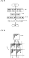
- the print medium is sheet-like or thin plate-like, and the colored image is formed on one main surface of the print medium and the code image is formed on the other main surface of the print medium.
- the clear ink may be ultraviolet visible ink.
- the inkjet printer further comprises another ejection mechanism for ejecting fine droplets of colored ink from a plurality of outlets; wherein the another ejection mechanism is controlled together with the moving mechanism by the print controller, to form the colored image on the print medium.
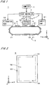
- the ejection mechanism 31b at the (+Y) side of the ejection mechanism 31a ejects K (black) colored ink
- the ejection mechanism 31b at the (+Y) side of the ejection mechanism 31a ejects C (cyan) colored ink
- the ejection mechanism 31c at the (+Y) side of the ejection mechanism 31b ejects M (magenta) colored ink
- the ejection mechanism 31d at the (+Y) side of the ejection mechanism 31c ejects Y (yellow) colored ink in the ejection part 3, the ejection mechanism 32 lying on the outermost (+Y) side in Fig. 1 ejects clear ink.
- invisible ink which is made visible by irradiation of ultraviolet i.e., ultraviolet visible ink
- invisible ink which is made visible by irradiation of ultraviolet (i.e., ultraviolet visible ink) is utilized as the clear ink.
- Step S12 forming of the colored image (Step S12) and coating of the colored image (Step S13) are sequentially performed for each portion of the print medium 9 in the Y direction, and therefore, for the whole print medium 9, forming of the colored image (Step S12) and coating of the colored image (Step S13) are performed almost in parallel (the same applies to after-mentioned Step S22 and Step S23 in Fig. 6 ).
- each dot of the colored image is coated with a dot of clear ink having the same size.
- the dots of the colored image may be coated with dots of the clear ink having larger size than the dots of the colored image. Therefore, if a landing position of the clear ink (i.e., the position where a droplet of the clear ink is applied) is slightly off from a dot of the colored image, the dot of the colored image is certainly coated with the clear ink.
- a tint part of the colored image there may be a case where the tint part is uniformly coated with the clear ink over the whole surface with no space, and ejection of the clear ink is controlled so that a total area of dots of the clear ink which is applied onto the tint part becomes a predetermined percent of an area of the tint part (the percent is a predetermined percent more than 0% and less than 100%, for example 50%), to apply the clear ink onto the tint part uniformly. Since the total area of dots of the clear ink is made less than the area of the tint part, drying of the colored ink in the tint part is promoted.
- the clear ink is ejected toward the blank area 93 on the first main surface 91 of the print medium 9 (in the present embodiment, toward a portion of the blank area 93 lying on the (+X) side or (-X) side of the colored image print area 92) in parallel with coating the colored image with the clear ink in Step S13, to thereby form the code image on the blank area 93 with the clear ink (Step S14).
- the coating of the colored image and forming of the code image for the blank area 93 around the colored image i.e., formation of the code image performed with avoiding the colored image
- the identical clear ink ejected from the one ejection mechanism 32 is performed on the first main surface 91 of the print medium 9 where the colored image is formed.
- the original print medium 9 is easily distinguished from a copy of the print medium 9 or the like, and security of the colored image on the print medium 9 is improved.
- the inkjet printer 1 the above-mentioned printing is sequentially performed for a plurality of print media 9 (the same applies to the following other embodiments).
- the coating of the colored image and the forming of the code image are performed with the same clear ink ejected from the one ejection mechanism 32. Therefore, structure of the inkjet printer 1 is simplified, and improvement of wear resistance and improvement of security of the colored image can be achieved while reducing manufacturing cost of the apparatus. In addition, printing cost for the print medium 9 can be reduced.
- the ultraviolet visible ink is utilized as the clear ink
- readout of the code image on the print medium 9 can be easily performed with use of relatively inexpensive and easy-to-use black light or the like, and without using an expensive instrument, equipment or the like.
- the code image is made grayscale, inability to detect the code image due to a short ejection amount of the clear ink or exposure of the code image under normal illumination due to an excessive ejection amount of the clear ink is prevented and forming code information with high accuracy is achieved.
- outlets used for the forming of the code image are made different from outlets used for the coating of the colored image in the ejection mechanism 32. Therefore, ejection control of the clear ink from the outlets in the ejection mechanism 32 which are used for the coating of the colored image is performed on the basis of only the first halftone image data, and ejection control of the clear ink from the outlets which are used for the forming of the code image is performed on the basis of only the second halftone image data. As the result, control of the ejection mechanism 32 is simplified.
- the code image is formed on the blank area 93 around the colored image, the coating of the colored image and the forming of the code image can be easily performed in parallel. As the result, the printing for the print medium 9 can be performed quickly.
- the moving mechanism 2 for moving the print medium 9 relative to the ejection part 3 can be simplified and the printing for the print medium 9 can be performed more quickly.
- the moving mechanism 2 used for the coating of the colored image and the forming of the code image is controlled together with the ejection mechanisms 31a to 31d of the ejection part 3 by the print controller 4, to perform forming the colored image on the print medium 9.
- the code image is formed on the blank area 93 around the colored image on the first main surface 91 of the print medium 9 shown in Fig. 2 .
- a code image may be formed on the colored image formed on the colored image print area 92.
- ejection amounts of the clear ink from a group of outlets, which is opposed to the colored image print area 92, in the ejection mechanism 32 are set at a predetermined amount so as to uniformly coat the whole colored image print area 92 with the clear ink with no space, and furthermore, control to increase the ejection amount of the clear ink from an outlet, which corresponds to each dot of the code image, by approximately 20% to 30% of the above predetermined amount is performed by the print controller 4 on the basis of the second halftone image data.
- the colored image print area 92 where the colored image is formed is coated with the clear ink over the whole surface, and heights of portions, corresponding to the code image, in the coating layer of the clear ink are made higher than that of the surround.
- the code image since the code image is formed on the colored image, visual recognition of the code image can be made more difficult in the state where ambient light is irradiated.
- the code image may be formed on both the colored image and the blank area 93.
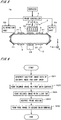
- FIG. 5 is a view showing a constitution of the inkjet printer 1a in accordance with the second embodiment.
- the constituents of the inkjet printer 1a are same as those of the inkjet printer 1 shown in Fig. 1 except for the point where the moving mechanism 2 has a reversal mechanism 24 at the lower side of the guide 22, and in the following description, constituents corresponding to respective constituents of the inkjet printer 1 are denoted by the same reference signs.
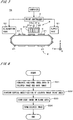
- Fig. 6 is a flowchart showing an operation flow of printing by the inkjet printer 1a.
- the first halftone image data representing the colored image and the second halftone image data representing the code image are generated in the print controller 4 in the same manner as the first embodiment (Step S21).
- the print medium 9 is supplied from the supply part 51 onto a stage 21 to be held thereon, and the moving mechanism 2 and the ejection mechanisms 31a to 31d, 32 in the ejection part 3 are controlled by the print controller 4, thereby to form the colored image on the colored image print area 92 (see Fig. 2 ) of the first main surface 91 of the print medium 9 (Step S22) and to perform coating the colored image with the clear ink (Step S23).
- the print medium 9 where the forming of the colored image and the coating of the colored image are completed moves in a counterclockwise direction in Fig. 5 by movement of the belt inside the guide 22 of the moving mechanism 2, and it reaches at the reversal mechanism 24 without being withdrawn by the elimination part 52.
- the print medium 9 is reversed by the reversal mechanism 24, and the first main surface 91 which is one main surface on which the colored image has been formed is held on the stage 21 by suction (Step S24).
- the print medium 9 moves in the counterclockwise direction to lie at the lower side of the ejection part 3 and a second main surface 94 (see Fig. 2 ) of the print medium 9 which is the other main surface is opposite to the ejection mechanism 32.
- the moving mechanism 2 and the ejection mechanism 32 are controlled by the print controller 4, and therefore ejection of the clear ink toward the second main surface 94 of the print medium 9 is performed to perform forming of the code image on the second main surface 94 (Step S25).
- the print medium 9 where the forming of the code image is completed is withdrawn by the elimination part 52.
- the code image is formed on the second main surface 94 which is different from the first main surface 91 on which the colored image is formed.
- the print medium 9 is supplied from the supply part 51 onto a stage 21 to be held thereon, and the moving mechanism 2 and the ejection mechanism 32 in the ejection part 3 are controlled by print controller 4. Therefore, the clear ink is uniformly ejected from outlets, which are opposed to the colored image print area 92 (see Fig. 2 ) of the print medium 9 on which the colored image is to be formed, out of the plurality of outlets in the ejection mechanism 32 toward the colored image print area 92, to perform surface modification of the colored image print area 92 on the first main surface 91 (see Fig. 2 ) of the print medium 9 (Step S32). In addition, ejection of the clear ink from outlets, which are opposed to the blank area 93 (see Fig.
- the colored ink is ejected toward portions of the colored image print area 92 (i.e., the colored image print area 92 after the surface modification) having passed under the ejection mechanism 32, to perform forming of the colored image (Step S34).
- modifying the surface and forming the code image (Step S32, S33), and forming the colored image (Step S34) are sequentially performed on each portion of the print medium 9 in the Y direction, and therefore for the whole print medium 9, modifying the surface and forming the code image (Step S32, S33), and forming the colored image (Step S34) are performed in almost parallel.
- the code image is formed on the blank area 93 around the colored image
- the surface modification of the print medium 9 can be easily performed in parallel with the forming of the code image. Therefore, the printing for the print medium 9 can be performed quickly.
- the surface modification with the clear ink may be also performed on the blank area 93.
- the moving mechanism 2 used for the surface modification of the print medium 9 and the forming of the code image is controlled together with the ejection mechanisms 31a to 31d in the ejection part 3 by the print controller 4, to perform the forming of the colored image on the print medium 9.
- the print medium 9 where the surface modification and the forming of the colored image are completed reaches at the reversal mechanism 24 without being withdrawn by the elimination part 52, and it is reversed by the reversal mechanism 24 (Step S44). After that, the print medium 9 moves to the lower side of the ejection part 3 and the moving mechanism 2 and the ejection mechanism 32 are controlled by the print controller 4 to perform forming of the code image on the second main surface 94 of the print medium 9 (Step S45). The print medium 9 where the forming of the code image is completed is withdrawn by the elimination part 52.
- the surface modification of the print medium 9 and the forming of the code image are performed with the same clear ink ejected from the one ejection mechanism 32. Therefore, the surface modification of the print medium 9 and the forming of high accuracy and high quality colored image by the modification, and improvement of security of the colored image on the print medium 9 can be achieved while reducing manufacturing cost of the apparatus without complicating structure of the inkjet printer 1c in a similar fashion to the third embodiment. In addition, printing cost for the print medium 9 can be reduced. Furthermore, control of the ejection mechanism 32 is simplified since the code image is formed on the second main surface 94.
- the coating of the colored image and the forming of the code image are performed with the same clear ink ejected from the one ejection mechanism 32 in a similar fashion to the first embodiment. Therefore, improvement of wear resistance and improvement of security of the colored image can be achieved while reducing manufacturing cost of the apparatus without complicating structure of the inkjet printer 1d.
- the scanner 102 may be omitted. Also another printing apparatus such as an electrophotographic printer may be provided as substitute for the offset printing apparatus 101.
- the inkjet printer 1d if the whole area of the colored image print area 92 is uniformly coated with the clear ink or the like, approximate positions of the colored image print area 92 and the blank area 93 have only to be detectable. Thus, as long as a guide for performing alignment of the print medium 9 by contacting edges of the print medium 9 or the like is provided in each stage 21 of the inkjet printer 1d, the scanner 102 can be omitted from the printer system 100.
- an ejection mechanism for ejecting the clear ink is provided also at the (+Y) side of the ejection mechanism 31d in the ejection part 3 and coating the colored image with the clear ink is performed as appropriate.
- the inkjet printers in accordance with the first to fourth embodiments may be utilized as a monochrome printer by omitting the ejection mechanism 31b to 31d from the ejection part 3.
- the code image may be formed by not multi-level dots (i.e., dots having a plurality of sizes) of the clear ink but one sized dots.
- each ejection head in the ejection part 3 in the X direction is made less than the width of the print medium 9 in the X direction, shuttle movement of the ejection part 3 in the X direction and movement of the print medium 9 toward the (+Y) direction are performed in parallel, and therefore printing for the print medium 9 is performed.
- the moving mechanism 2 do not always have to be a mechanism for moving the print medium 9, for example, it may be a mechanism for moving the ejection part 3 (i.e., the ejection mechanisms 31a to 31d, 32) to move the print medium 9 relative to the ejection part 3.
- printing may be performed for a web which is continuous paper.
- printing is not necessarily performed on the sheet-like print medium 9 such as paper or film, and printing may be performed on print media in various forms such as a thin plate-like print medium or others.
Landscapes
- Ink Jet (AREA)
- Accessory Devices And Overall Control Thereof (AREA)
Claims (7)
- Tintenstrahldrucker (1), umfassend: einen Ausstoßmechanismus (32) zum Ausstoßen von feinen Tröpfchen klarer Tinte aus einer Vielzahl von Auslässen; und einen Bewegungsmechanismus (2) zum Bewegen eines Druckmediums (9) relativ zu dem Ausstoßmechanismus;
gekennzeichnet durch eine Drucksteuerung (4), die den Ausstoßmechanismus und den Bewegungsmechanismus steuert, um ein Farbbild auf dem Druckmedium mit der klaren Tinte zu beschichten und ein Codebild auf dem beschichteten Bereich entsprechend dem Farbbild mit der klaren Tinte auf der Basis von zweiten Halbton-Bilddaten zu erzeugen, wobei das Farbbild auf der Basis von ersten Halbton-Bilddaten gebildet wird,
wobei der Ausstoßmechanismus jede Position auf dem Druckmedium einmal durch eine einmalige relative Bewegung davon durchläuft, um das Farbbild mit der klaren Tinte zu beschichten und das Codebild mit der klaren Tinte zu bilden,
und wobei das Beschichten des Farbbildes und das Bilden des Codebildes parallel durchgeführt werden. - Tintenstrahldrucker nach Anspruch 1, wobei die Drucksteuerung Ausstoßmengen der klaren Tinte von den Auslässen des Ausstoßmechanismus auf eine vorbestimmte Menge einstellt, um das gesamte Farbbild gleichmäßig mit der klaren Tinte ohne Zwischenraum zu beschichten, und die Ausstoßmengen der klaren Tinte von einigen Auslässen des Ausstoßmechanismus um ungefähr 20% bis 30% der vorbestimmten Menge erhöht, wobei die genannten einigen Auslässe jedem Punkt des Codebildes entsprechen.
- Tintenstrahldrucker nach Anspruch 1 oder 2, wobei die klare Tinte eine UV-sichtbare Tinte ist.
- Tintenstrahldrucker nach einem der Ansprüche 1 bis 3, ferner umfassend einen weiteren Ausstoßmechanismus (31a bis 31d) zum Ausstoßen von feinen Tröpfchen farbiger Tinte aus einer Mehrzahl von Auslässen; wobei der weitere Ausstoßmechanismus zusammen mit dem Bewegungsmechanismus durch die Drucksteuerung gesteuert wird, um das Farbbild auf dem Druckmedium zu erzeugen.
- Tintenstrahldruckverfahren, umfassend den Schritt:a) Ausstoßen feiner Tropfen klarer Tinte aus einer Mehrzahl von Auslässen in einem Ausstoßmechanismus (32) und Bewegen eines Druckmediums (9) relativ zu dem Ausstoßmechanismus, um ein Farbbild auf dem Druckmedium mit der klaren Tinte zu beschichten, wobei das Farbbild auf der Basis von ersten Halbton-Bilddaten gebildet wird; gekennzeichnet durch den Schrittb) Ausstoßen feiner Tröpfchen der klaren Tinte aus der Vielzahl von Auslässen und Bewegen des Druckmediums relativ zu dem Ausstoßmechanismus, um ein Codebild auf dem Farbbild entsprechenden beschichteten Bereich mit der klaren Tinte auf der Grundlage der zweiten Halbton-Bilddaten zu erzeugen,wobei der Ausstoßmechanismus jede Position auf dem Druckmedium einmal durch eine einmalige relative Bewegung davon durchläuft, um das Farbbild mit der klaren Tinte zu beschichten und das Codebild mit der klaren Tinte zu bilden, und
wobei das Beschichten des Farbbildes und das Bilden des Codebildes parallel durchgeführt werden. - Tintenstrahldruckverfahren nach Anspruch 5,
wobei Ausstoßmengen der klaren Tinte von den Auslässen des Ausstoßmechanismus auf eine vorbestimmte Menge eingestellt werden, um das gesamte Farbbild mit der klaren Tinte ohne Zwischenraum gleichmäßig zu beschichten, und die Ausstoßmengen der klaren Tinte von einigen Auslässen des Ausstoßmechanismus um ungefähr 20% bis 30% der vorbestimmten Menge erhöht werden, wobei die genannten einigen Auslässe jedem Punkt des Codebildes entsprechen. - Tintenstrahldruckverfahren nach Anspruch 5 oder 6, wobei die klare Tinte eine UV-sichtbare Tinte ist.
Applications Claiming Priority (2)
| Application Number | Priority Date | Filing Date | Title |
|---|---|---|---|
| JP2009067668A JP5129771B2 (ja) | 2009-03-19 | 2009-03-19 | インクジェットプリンタおよびインクジェット方式の印刷方法 |
| PCT/JP2010/053503 WO2010106918A1 (ja) | 2009-03-19 | 2010-03-04 | インクジェットプリンタおよびインクジェット方式の印刷方法 |
Publications (3)
| Publication Number | Publication Date |
|---|---|
| EP2409841A1 EP2409841A1 (de) | 2012-01-25 |
| EP2409841A4 EP2409841A4 (de) | 2014-05-14 |
| EP2409841B1 true EP2409841B1 (de) | 2018-06-13 |
Family
ID=42739581
Family Applications (1)
| Application Number | Title | Priority Date | Filing Date |
|---|---|---|---|
| EP10753413.3A Not-in-force EP2409841B1 (de) | 2009-03-19 | 2010-03-04 | Tintenstrahldrucker und tintenstrahldruckverfahren |
Country Status (4)
| Country | Link |
|---|---|
| US (1) | US20110222126A1 (de) |
| EP (1) | EP2409841B1 (de) |
| JP (1) | JP5129771B2 (de) |
| WO (1) | WO2010106918A1 (de) |
Families Citing this family (21)
| Publication number | Priority date | Publication date | Assignee | Title |
|---|---|---|---|---|
| JP4950977B2 (ja) | 2008-10-08 | 2012-06-13 | キヤノン株式会社 | 画像形成装置 |
| JP5464913B2 (ja) * | 2009-06-01 | 2014-04-09 | キヤノン株式会社 | 画像形成装置、情報処理装置、画像形成装置の制御方法、情報処理装置の制御方法及びプログラム |
| JP5539117B2 (ja) * | 2010-08-31 | 2014-07-02 | キヤノン株式会社 | インクジェット記録装置およびインクジェット記録方法 |
| US8608272B2 (en) * | 2010-12-03 | 2013-12-17 | Xerox Corporation | System and method for inkjet printing with a differential halftoned protective overcoat with gloss compensation |
| JP5652253B2 (ja) * | 2011-02-24 | 2015-01-14 | セイコーエプソン株式会社 | 液体吐出装置 |
| JP5838564B2 (ja) * | 2011-02-24 | 2016-01-06 | セイコーエプソン株式会社 | 液体吐出装置 |
| JP5802037B2 (ja) * | 2011-03-29 | 2015-10-28 | 株式会社Screenホールディングス | 画像記録方法 |
| JP2012218233A (ja) * | 2011-04-06 | 2012-11-12 | Seiko Epson Corp | 液体噴射装置およびその制御方法 |
| JP5811589B2 (ja) * | 2011-05-18 | 2015-11-11 | セイコーエプソン株式会社 | 印刷装置及び印刷方法 |
| JP5955088B2 (ja) * | 2012-05-08 | 2016-07-20 | キヤノン株式会社 | 画像処理装置および画像処理方法 |
| US9700908B2 (en) | 2012-12-27 | 2017-07-11 | Kateeva, Inc. | Techniques for arrayed printing of a permanent layer with improved speed and accuracy |
| US11673155B2 (en) | 2012-12-27 | 2023-06-13 | Kateeva, Inc. | Techniques for arrayed printing of a permanent layer with improved speed and accuracy |
| US9352561B2 (en) | 2012-12-27 | 2016-05-31 | Kateeva, Inc. | Techniques for print ink droplet measurement and control to deposit fluids within precise tolerances |
| US9832428B2 (en) | 2012-12-27 | 2017-11-28 | Kateeva, Inc. | Fast measurement of droplet parameters in industrial printing system |
| KR20220001519A (ko) | 2012-12-27 | 2022-01-05 | 카티바, 인크. | 정밀 공차 내로 유체를 증착하기 위한 인쇄 잉크 부피 제어를 위한 기법 |
| US11141752B2 (en) | 2012-12-27 | 2021-10-12 | Kateeva, Inc. | Techniques for arrayed printing of a permanent layer with improved speed and accuracy |
| EP3079911B1 (de) | 2013-12-12 | 2020-07-29 | Kateeva, Inc. | Herstellung einer tintenbasierten schicht mithilfe der halbtonrasterung zur steuerung der dicke |
| DE102015218325A1 (de) * | 2015-09-24 | 2017-03-30 | Bhs Corrugated Maschinen- Und Anlagenbau Gmbh | Wellpappe-Anlage |
| US9956789B2 (en) * | 2015-10-07 | 2018-05-01 | Xerox Corporation | Systems and methods for implementing a post-processing scheme for minimizing curl in sets of output image receiving media substrates imaged in image forming devices |
| US9747532B1 (en) | 2016-07-18 | 2017-08-29 | Ricoh Company, Ltd. | Multi-level protector coat bitmap generation for printing systems |
| CN106393967A (zh) * | 2016-08-29 | 2017-02-15 | 浙江新长海新材料股份有限公司 | 一种包装袋自动印码机 |
Family Cites Families (13)
| Publication number | Priority date | Publication date | Assignee | Title |
|---|---|---|---|---|
| JP3224491B2 (ja) * | 1995-06-01 | 2001-10-29 | キヤノン株式会社 | 画像処理装置及びその方法 |
| JPH09174823A (ja) * | 1995-12-27 | 1997-07-08 | Canon Inc | インクジェット記録装置及び画像形成方法 |
| JP3774505B2 (ja) * | 1996-04-23 | 2006-05-17 | キヤノン株式会社 | 中間調記録装置、中間調記録方法、インクタンク、ヘッドカートリッジ、インクジェット記録装置及びインクジェット記録方法 |
| JP3347647B2 (ja) * | 1997-07-28 | 2002-11-20 | キヤノン株式会社 | インクジェット記録装置およびインクジェット記録方法 |
| JPH11268457A (ja) | 1998-03-23 | 1999-10-05 | Toppan Printing Co Ltd | オーバーコート装置及びオーバーコート方法 |
| US7246239B2 (en) * | 2001-01-24 | 2007-07-17 | Digimarc Corporation | Digital watermarks for checking authenticity of printed objects |
| JP3835383B2 (ja) * | 2002-09-09 | 2006-10-18 | セイコーエプソン株式会社 | 液体吐出装置及びコンピュータシステム |
| JP2005119013A (ja) * | 2003-10-14 | 2005-05-12 | Ricoh Co Ltd | 画像形成装置 |
| JP2006027193A (ja) * | 2004-07-21 | 2006-02-02 | Konica Minolta Holdings Inc | インクジェット記録方法及びインクジェット記録装置 |
| JP2006096005A (ja) * | 2004-09-30 | 2006-04-13 | Fuji Photo Film Co Ltd | カード情報記録媒体およびその製造方法 |
| EP1705529A1 (de) * | 2005-03-22 | 2006-09-27 | Eastman Kodak Company | Verfahren und Vorrichtung zum Steuern von differentiellem Glanz und derartig gedrucktes Erzeugnis |
| JP2007021925A (ja) * | 2005-07-19 | 2007-02-01 | Seiko Epson Corp | インクジェット記録方法 |
| JP2008126628A (ja) * | 2006-11-24 | 2008-06-05 | Canon Inc | インクジェット記録装置および記録方法 |
-
2009
- 2009-03-19 JP JP2009067668A patent/JP5129771B2/ja not_active Expired - Fee Related
-
2010
- 2010-03-04 EP EP10753413.3A patent/EP2409841B1/de not_active Not-in-force
- 2010-03-04 WO PCT/JP2010/053503 patent/WO2010106918A1/ja active Application Filing
- 2010-03-04 US US13/128,505 patent/US20110222126A1/en not_active Abandoned
Non-Patent Citations (1)
| Title |
|---|
| None * |
Also Published As
| Publication number | Publication date |
|---|---|
| JP5129771B2 (ja) | 2013-01-30 |
| WO2010106918A1 (ja) | 2010-09-23 |
| US20110222126A1 (en) | 2011-09-15 |
| EP2409841A4 (de) | 2014-05-14 |
| EP2409841A1 (de) | 2012-01-25 |
| JP2010214928A (ja) | 2010-09-30 |
Similar Documents
| Publication | Publication Date | Title |
|---|---|---|
| EP2409841B1 (de) | Tintenstrahldrucker und tintenstrahldruckverfahren | |
| US8605303B2 (en) | Content-aware image quality defect detection in printed documents | |
| US7484821B2 (en) | Method of determining ink ejection method, printing apparatus, and method of manufacturing printing apparatus | |
| JP4822712B2 (ja) | 画像形成装置、画像処理方法及びプログラム | |
| JP4909321B2 (ja) | 画像処理方法、プログラム、画像処理装置、画像形成装置及び画像形成システム | |
| US8608272B2 (en) | System and method for inkjet printing with a differential halftoned protective overcoat with gloss compensation | |
| US8511788B2 (en) | Image recording method and apparatus | |
| US11778123B2 (en) | Artifact compensation mechanism | |
| US8646862B2 (en) | System and method for detection and compensation of inoperable inkjets in an inkjet printing apparatus | |
| US8967751B2 (en) | Image processing apparatus and image processing method | |
| EP1734736B1 (de) | Ausgleich für defekte Düsen | |
| US20230123461A1 (en) | Artifact compensation mechanism | |
| US8864256B2 (en) | Image processing apparatus for processing multivalue image data in an area corresponding to an overlapped portion of nozzle arrays | |
| US8824014B1 (en) | System and method for adjustment of coverage parameters for different colors in image data | |
| US9738066B1 (en) | System and method for image data processing for inoperable inkjet compensation in an inkjet printer | |
| US8960839B1 (en) | System and method for spatial dependent correction for images printed with multiple drop parameters | |
| JP3996857B2 (ja) | インクジェットプリンタ,及びインクジェットプリントシステム | |
| US20110193905A1 (en) | Printing device | |
| US6491374B1 (en) | Methods and apparatuses for printing with uniform and non-uniform print mask functions | |
| US9211746B1 (en) | Hybrid printer for printing on non-porous media | |
| US20110310154A1 (en) | System And Method For Preserving Edges While Enabling Inkjet Correction Within An Interior Of An Image | |
| US11516361B2 (en) | Image forming apparatus and image forming method | |
| US6211893B1 (en) | Multi-gradation recording method | |
| JP2005349659A (ja) | 記録方法及び記録装置 | |
| JP5816041B2 (ja) | カラーインクジェット印刷装置 |
Legal Events
| Date | Code | Title | Description |
|---|---|---|---|
| PUAI | Public reference made under article 153(3) epc to a published international application that has entered the european phase |
Free format text: ORIGINAL CODE: 0009012 |
|
| 17P | Request for examination filed |
Effective date: 20110414 |
|
| AK | Designated contracting states |
Kind code of ref document: A1 Designated state(s): AT BE BG CH CY CZ DE DK EE ES FI FR GB GR HR HU IE IS IT LI LT LU LV MC MK MT NL NO PL PT RO SE SI SK SM TR |
|
| DAX | Request for extension of the european patent (deleted) | ||
| A4 | Supplementary search report drawn up and despatched |
Effective date: 20140416 |
|
| RIC1 | Information provided on ipc code assigned before grant |
Ipc: B41J 2/21 20060101ALI20140410BHEP Ipc: H04N 21/8358 20110101ALI20140410BHEP Ipc: B41J 11/00 20060101ALI20140410BHEP Ipc: B41J 2/01 20060101AFI20140410BHEP Ipc: B41J 29/00 20060101ALI20140410BHEP |
|
| RAP1 | Party data changed (applicant data changed or rights of an application transferred) |
Owner name: SCREEN HOLDINGS CO., LTD. |
|
| STAA | Information on the status of an ep patent application or granted ep patent |
Free format text: STATUS: EXAMINATION IS IN PROGRESS |
|
| 17Q | First examination report despatched |
Effective date: 20170119 |
|
| GRAP | Despatch of communication of intention to grant a patent |
Free format text: ORIGINAL CODE: EPIDOSNIGR1 |
|
| STAA | Information on the status of an ep patent application or granted ep patent |
Free format text: STATUS: GRANT OF PATENT IS INTENDED |
|
| RIC1 | Information provided on ipc code assigned before grant |
Ipc: B41J 11/00 20060101ALI20180214BHEP Ipc: B41M 7/00 20060101ALI20180214BHEP Ipc: H04N 21/8358 20110101ALI20180214BHEP Ipc: B41J 2/01 20060101AFI20180214BHEP Ipc: B41M 5/00 20060101ALI20180214BHEP Ipc: B41J 2/21 20060101ALI20180214BHEP Ipc: B41J 29/00 20060101ALI20180214BHEP |
|
| INTG | Intention to grant announced |
Effective date: 20180301 |
|
| GRAS | Grant fee paid |
Free format text: ORIGINAL CODE: EPIDOSNIGR3 |
|
| GRAA | (expected) grant |
Free format text: ORIGINAL CODE: 0009210 |
|
| STAA | Information on the status of an ep patent application or granted ep patent |
Free format text: STATUS: THE PATENT HAS BEEN GRANTED |
|
| AK | Designated contracting states |
Kind code of ref document: B1 Designated state(s): AT BE BG CH CY CZ DE DK EE ES FI FR GB GR HR HU IE IS IT LI LT LU LV MC MK MT NL NO PL PT RO SE SI SK SM TR |
|
| REG | Reference to a national code |
Ref country code: GB Ref legal event code: FG4D |
|
| REG | Reference to a national code |
Ref country code: CH Ref legal event code: EP Ref country code: AT Ref legal event code: REF Ref document number: 1008067 Country of ref document: AT Kind code of ref document: T Effective date: 20180615 |
|
| REG | Reference to a national code |
Ref country code: IE Ref legal event code: FG4D |
|
| REG | Reference to a national code |
Ref country code: DE Ref legal event code: R096 Ref document number: 602010051276 Country of ref document: DE |
|
| REG | Reference to a national code |
Ref country code: NL Ref legal event code: MP Effective date: 20180613 |
|
| REG | Reference to a national code |
Ref country code: LT Ref legal event code: MG4D |
|
| PG25 | Lapsed in a contracting state [announced via postgrant information from national office to epo] |
Ref country code: CY Free format text: LAPSE BECAUSE OF FAILURE TO SUBMIT A TRANSLATION OF THE DESCRIPTION OR TO PAY THE FEE WITHIN THE PRESCRIBED TIME-LIMIT Effective date: 20180613 Ref country code: LT Free format text: LAPSE BECAUSE OF FAILURE TO SUBMIT A TRANSLATION OF THE DESCRIPTION OR TO PAY THE FEE WITHIN THE PRESCRIBED TIME-LIMIT Effective date: 20180613 Ref country code: SE Free format text: LAPSE BECAUSE OF FAILURE TO SUBMIT A TRANSLATION OF THE DESCRIPTION OR TO PAY THE FEE WITHIN THE PRESCRIBED TIME-LIMIT Effective date: 20180613 Ref country code: ES Free format text: LAPSE BECAUSE OF FAILURE TO SUBMIT A TRANSLATION OF THE DESCRIPTION OR TO PAY THE FEE WITHIN THE PRESCRIBED TIME-LIMIT Effective date: 20180613 Ref country code: NO Free format text: LAPSE BECAUSE OF FAILURE TO SUBMIT A TRANSLATION OF THE DESCRIPTION OR TO PAY THE FEE WITHIN THE PRESCRIBED TIME-LIMIT Effective date: 20180913 Ref country code: BG Free format text: LAPSE BECAUSE OF FAILURE TO SUBMIT A TRANSLATION OF THE DESCRIPTION OR TO PAY THE FEE WITHIN THE PRESCRIBED TIME-LIMIT Effective date: 20180913 Ref country code: FI Free format text: LAPSE BECAUSE OF FAILURE TO SUBMIT A TRANSLATION OF THE DESCRIPTION OR TO PAY THE FEE WITHIN THE PRESCRIBED TIME-LIMIT Effective date: 20180613 |
|
| PG25 | Lapsed in a contracting state [announced via postgrant information from national office to epo] |
Ref country code: LV Free format text: LAPSE BECAUSE OF FAILURE TO SUBMIT A TRANSLATION OF THE DESCRIPTION OR TO PAY THE FEE WITHIN THE PRESCRIBED TIME-LIMIT Effective date: 20180613 Ref country code: GR Free format text: LAPSE BECAUSE OF FAILURE TO SUBMIT A TRANSLATION OF THE DESCRIPTION OR TO PAY THE FEE WITHIN THE PRESCRIBED TIME-LIMIT Effective date: 20180914 Ref country code: HR Free format text: LAPSE BECAUSE OF FAILURE TO SUBMIT A TRANSLATION OF THE DESCRIPTION OR TO PAY THE FEE WITHIN THE PRESCRIBED TIME-LIMIT Effective date: 20180613 |
|
| REG | Reference to a national code |
Ref country code: AT Ref legal event code: MK05 Ref document number: 1008067 Country of ref document: AT Kind code of ref document: T Effective date: 20180613 |
|
| PG25 | Lapsed in a contracting state [announced via postgrant information from national office to epo] |
Ref country code: NL Free format text: LAPSE BECAUSE OF FAILURE TO SUBMIT A TRANSLATION OF THE DESCRIPTION OR TO PAY THE FEE WITHIN THE PRESCRIBED TIME-LIMIT Effective date: 20180613 |
|
| PG25 | Lapsed in a contracting state [announced via postgrant information from national office to epo] |
Ref country code: IS Free format text: LAPSE BECAUSE OF FAILURE TO SUBMIT A TRANSLATION OF THE DESCRIPTION OR TO PAY THE FEE WITHIN THE PRESCRIBED TIME-LIMIT Effective date: 20181013 Ref country code: AT Free format text: LAPSE BECAUSE OF FAILURE TO SUBMIT A TRANSLATION OF THE DESCRIPTION OR TO PAY THE FEE WITHIN THE PRESCRIBED TIME-LIMIT Effective date: 20180613 Ref country code: EE Free format text: LAPSE BECAUSE OF FAILURE TO SUBMIT A TRANSLATION OF THE DESCRIPTION OR TO PAY THE FEE WITHIN THE PRESCRIBED TIME-LIMIT Effective date: 20180613 Ref country code: RO Free format text: LAPSE BECAUSE OF FAILURE TO SUBMIT A TRANSLATION OF THE DESCRIPTION OR TO PAY THE FEE WITHIN THE PRESCRIBED TIME-LIMIT Effective date: 20180613 Ref country code: SK Free format text: LAPSE BECAUSE OF FAILURE TO SUBMIT A TRANSLATION OF THE DESCRIPTION OR TO PAY THE FEE WITHIN THE PRESCRIBED TIME-LIMIT Effective date: 20180613 Ref country code: PL Free format text: LAPSE BECAUSE OF FAILURE TO SUBMIT A TRANSLATION OF THE DESCRIPTION OR TO PAY THE FEE WITHIN THE PRESCRIBED TIME-LIMIT Effective date: 20180613 Ref country code: CZ Free format text: LAPSE BECAUSE OF FAILURE TO SUBMIT A TRANSLATION OF THE DESCRIPTION OR TO PAY THE FEE WITHIN THE PRESCRIBED TIME-LIMIT Effective date: 20180613 |
|
| PG25 | Lapsed in a contracting state [announced via postgrant information from national office to epo] |
Ref country code: IT Free format text: LAPSE BECAUSE OF FAILURE TO SUBMIT A TRANSLATION OF THE DESCRIPTION OR TO PAY THE FEE WITHIN THE PRESCRIBED TIME-LIMIT Effective date: 20180613 Ref country code: SM Free format text: LAPSE BECAUSE OF FAILURE TO SUBMIT A TRANSLATION OF THE DESCRIPTION OR TO PAY THE FEE WITHIN THE PRESCRIBED TIME-LIMIT Effective date: 20180613 |
|
| REG | Reference to a national code |
Ref country code: DE Ref legal event code: R097 Ref document number: 602010051276 Country of ref document: DE |
|
| PLBE | No opposition filed within time limit |
Free format text: ORIGINAL CODE: 0009261 |
|
| STAA | Information on the status of an ep patent application or granted ep patent |
Free format text: STATUS: NO OPPOSITION FILED WITHIN TIME LIMIT |
|
| 26N | No opposition filed |
Effective date: 20190314 |
|
| PG25 | Lapsed in a contracting state [announced via postgrant information from national office to epo] |
Ref country code: DK Free format text: LAPSE BECAUSE OF FAILURE TO SUBMIT A TRANSLATION OF THE DESCRIPTION OR TO PAY THE FEE WITHIN THE PRESCRIBED TIME-LIMIT Effective date: 20180613 Ref country code: SI Free format text: LAPSE BECAUSE OF FAILURE TO SUBMIT A TRANSLATION OF THE DESCRIPTION OR TO PAY THE FEE WITHIN THE PRESCRIBED TIME-LIMIT Effective date: 20180613 |
|
| PGFP | Annual fee paid to national office [announced via postgrant information from national office to epo] |
Ref country code: DE Payment date: 20190507 Year of fee payment: 10 |
|
| PGFP | Annual fee paid to national office [announced via postgrant information from national office to epo] |
Ref country code: FR Payment date: 20190521 Year of fee payment: 10 |
|
| PG25 | Lapsed in a contracting state [announced via postgrant information from national office to epo] |
Ref country code: MC Free format text: LAPSE BECAUSE OF FAILURE TO SUBMIT A TRANSLATION OF THE DESCRIPTION OR TO PAY THE FEE WITHIN THE PRESCRIBED TIME-LIMIT Effective date: 20180613 |
|
| PGFP | Annual fee paid to national office [announced via postgrant information from national office to epo] |
Ref country code: GB Payment date: 20190523 Year of fee payment: 10 |
|
| REG | Reference to a national code |
Ref country code: CH Ref legal event code: PL |
|
| PG25 | Lapsed in a contracting state [announced via postgrant information from national office to epo] |
Ref country code: LU Free format text: LAPSE BECAUSE OF NON-PAYMENT OF DUE FEES Effective date: 20190304 |
|
| REG | Reference to a national code |
Ref country code: BE Ref legal event code: MM Effective date: 20190331 |
|
| PG25 | Lapsed in a contracting state [announced via postgrant information from national office to epo] |
Ref country code: LI Free format text: LAPSE BECAUSE OF NON-PAYMENT OF DUE FEES Effective date: 20190331 Ref country code: IE Free format text: LAPSE BECAUSE OF NON-PAYMENT OF DUE FEES Effective date: 20190304 Ref country code: CH Free format text: LAPSE BECAUSE OF NON-PAYMENT OF DUE FEES Effective date: 20190331 |
|
| PG25 | Lapsed in a contracting state [announced via postgrant information from national office to epo] |
Ref country code: BE Free format text: LAPSE BECAUSE OF NON-PAYMENT OF DUE FEES Effective date: 20190331 |
|
| PG25 | Lapsed in a contracting state [announced via postgrant information from national office to epo] |
Ref country code: TR Free format text: LAPSE BECAUSE OF FAILURE TO SUBMIT A TRANSLATION OF THE DESCRIPTION OR TO PAY THE FEE WITHIN THE PRESCRIBED TIME-LIMIT Effective date: 20180613 |
|
| PG25 | Lapsed in a contracting state [announced via postgrant information from national office to epo] |
Ref country code: PT Free format text: LAPSE BECAUSE OF FAILURE TO SUBMIT A TRANSLATION OF THE DESCRIPTION OR TO PAY THE FEE WITHIN THE PRESCRIBED TIME-LIMIT Effective date: 20181015 Ref country code: MT Free format text: LAPSE BECAUSE OF NON-PAYMENT OF DUE FEES Effective date: 20190304 |
|
| REG | Reference to a national code |
Ref country code: DE Ref legal event code: R119 Ref document number: 602010051276 Country of ref document: DE |
|
| PG25 | Lapsed in a contracting state [announced via postgrant information from national office to epo] |
Ref country code: DE Free format text: LAPSE BECAUSE OF NON-PAYMENT OF DUE FEES Effective date: 20201001 Ref country code: FR Free format text: LAPSE BECAUSE OF NON-PAYMENT OF DUE FEES Effective date: 20200331 |
|
| GBPC | Gb: european patent ceased through non-payment of renewal fee |
Effective date: 20200304 |
|
| PG25 | Lapsed in a contracting state [announced via postgrant information from national office to epo] |
Ref country code: GB Free format text: LAPSE BECAUSE OF NON-PAYMENT OF DUE FEES Effective date: 20200304 |
|
| PG25 | Lapsed in a contracting state [announced via postgrant information from national office to epo] |
Ref country code: HU Free format text: LAPSE BECAUSE OF FAILURE TO SUBMIT A TRANSLATION OF THE DESCRIPTION OR TO PAY THE FEE WITHIN THE PRESCRIBED TIME-LIMIT; INVALID AB INITIO Effective date: 20100304 |
|
| PG25 | Lapsed in a contracting state [announced via postgrant information from national office to epo] |
Ref country code: MK Free format text: LAPSE BECAUSE OF FAILURE TO SUBMIT A TRANSLATION OF THE DESCRIPTION OR TO PAY THE FEE WITHIN THE PRESCRIBED TIME-LIMIT Effective date: 20180613 |