EP2409548B1 - Electrical system using high frequency ac and having inductively connected loads, and corresponding power supplies and luminaires - Google Patents
Electrical system using high frequency ac and having inductively connected loads, and corresponding power supplies and luminaires Download PDFInfo
- Publication number
- EP2409548B1 EP2409548B1 EP10714355.4A EP10714355A EP2409548B1 EP 2409548 B1 EP2409548 B1 EP 2409548B1 EP 10714355 A EP10714355 A EP 10714355A EP 2409548 B1 EP2409548 B1 EP 2409548B1
- Authority
- EP
- European Patent Office
- Prior art keywords
- power
- twisted pair
- distribution system
- high frequency
- power distribution
- Prior art date
- Legal status (The legal status is an assumption and is not a legal conclusion. Google has not performed a legal analysis and makes no representation as to the accuracy of the status listed.)
- Active
Links
Images

Classifications
-
- H—ELECTRICITY
- H05—ELECTRIC TECHNIQUES NOT OTHERWISE PROVIDED FOR
- H05B—ELECTRIC HEATING; ELECTRIC LIGHT SOURCES NOT OTHERWISE PROVIDED FOR; CIRCUIT ARRANGEMENTS FOR ELECTRIC LIGHT SOURCES, IN GENERAL
- H05B45/00—Circuit arrangements for operating light-emitting diodes [LED]
- H05B45/30—Driver circuits
- H05B45/355—Power factor correction [PFC]; Reactive power compensation
-
- H—ELECTRICITY
- H05—ELECTRIC TECHNIQUES NOT OTHERWISE PROVIDED FOR
- H05B—ELECTRIC HEATING; ELECTRIC LIGHT SOURCES NOT OTHERWISE PROVIDED FOR; CIRCUIT ARRANGEMENTS FOR ELECTRIC LIGHT SOURCES, IN GENERAL
- H05B45/00—Circuit arrangements for operating light-emitting diodes [LED]
- H05B45/30—Driver circuits
- H05B45/31—Phase-control circuits
-
- H—ELECTRICITY
- H05—ELECTRIC TECHNIQUES NOT OTHERWISE PROVIDED FOR
- H05B—ELECTRIC HEATING; ELECTRIC LIGHT SOURCES NOT OTHERWISE PROVIDED FOR; CIRCUIT ARRANGEMENTS FOR ELECTRIC LIGHT SOURCES, IN GENERAL
- H05B45/00—Circuit arrangements for operating light-emitting diodes [LED]
- H05B45/30—Driver circuits
- H05B45/32—Pulse-control circuits
- H05B45/325—Pulse-width modulation [PWM]
-
- H—ELECTRICITY
- H05—ELECTRIC TECHNIQUES NOT OTHERWISE PROVIDED FOR
- H05B—ELECTRIC HEATING; ELECTRIC LIGHT SOURCES NOT OTHERWISE PROVIDED FOR; CIRCUIT ARRANGEMENTS FOR ELECTRIC LIGHT SOURCES, IN GENERAL
- H05B45/00—Circuit arrangements for operating light-emitting diodes [LED]
- H05B45/30—Driver circuits
- H05B45/37—Converter circuits
- H05B45/3725—Switched mode power supply [SMPS]
- H05B45/382—Switched mode power supply [SMPS] with galvanic isolation between input and output
-
- H—ELECTRICITY
- H05—ELECTRIC TECHNIQUES NOT OTHERWISE PROVIDED FOR
- H05B—ELECTRIC HEATING; ELECTRIC LIGHT SOURCES NOT OTHERWISE PROVIDED FOR; CIRCUIT ARRANGEMENTS FOR ELECTRIC LIGHT SOURCES, IN GENERAL
- H05B45/00—Circuit arrangements for operating light-emitting diodes [LED]
- H05B45/30—Driver circuits
- H05B45/37—Converter circuits
- H05B45/3725—Switched mode power supply [SMPS]
- H05B45/39—Circuits containing inverter bridges
-
- H—ELECTRICITY
- H02—GENERATION; CONVERSION OR DISTRIBUTION OF ELECTRIC POWER
- H02M—APPARATUS FOR CONVERSION BETWEEN AC AND AC, BETWEEN AC AND DC, OR BETWEEN DC AND DC, AND FOR USE WITH MAINS OR SIMILAR POWER SUPPLY SYSTEMS; CONVERSION OF DC OR AC INPUT POWER INTO SURGE OUTPUT POWER; CONTROL OR REGULATION THEREOF
- H02M3/00—Conversion of DC power input into DC power output
- H02M3/01—Resonant DC/DC converters
-
- H—ELECTRICITY
- H02—GENERATION; CONVERSION OR DISTRIBUTION OF ELECTRIC POWER
- H02M—APPARATUS FOR CONVERSION BETWEEN AC AND AC, BETWEEN AC AND DC, OR BETWEEN DC AND DC, AND FOR USE WITH MAINS OR SIMILAR POWER SUPPLY SYSTEMS; CONVERSION OF DC OR AC INPUT POWER INTO SURGE OUTPUT POWER; CONTROL OR REGULATION THEREOF
- H02M3/00—Conversion of DC power input into DC power output
- H02M3/22—Conversion of DC power input into DC power output with intermediate conversion into AC
- H02M3/24—Conversion of DC power input into DC power output with intermediate conversion into AC by static converters
- H02M3/28—Conversion of DC power input into DC power output with intermediate conversion into AC by static converters using discharge tubes with control electrode or semiconductor devices with control electrode to produce the intermediate AC
- H02M3/325—Conversion of DC power input into DC power output with intermediate conversion into AC by static converters using discharge tubes with control electrode or semiconductor devices with control electrode to produce the intermediate AC using devices of a triode or a transistor type requiring continuous application of a control signal
- H02M3/335—Conversion of DC power input into DC power output with intermediate conversion into AC by static converters using discharge tubes with control electrode or semiconductor devices with control electrode to produce the intermediate AC using devices of a triode or a transistor type requiring continuous application of a control signal using semiconductor devices only
- H02M3/33569—Conversion of DC power input into DC power output with intermediate conversion into AC by static converters using discharge tubes with control electrode or semiconductor devices with control electrode to produce the intermediate AC using devices of a triode or a transistor type requiring continuous application of a control signal using semiconductor devices only having several active switching elements
- H02M3/33571—Half-bridge at primary side of an isolation transformer
-
- H—ELECTRICITY
- H05—ELECTRIC TECHNIQUES NOT OTHERWISE PROVIDED FOR
- H05B—ELECTRIC HEATING; ELECTRIC LIGHT SOURCES NOT OTHERWISE PROVIDED FOR; CIRCUIT ARRANGEMENTS FOR ELECTRIC LIGHT SOURCES, IN GENERAL
- H05B45/00—Circuit arrangements for operating light-emitting diodes [LED]
- H05B45/30—Driver circuits
- H05B45/37—Converter circuits
- H05B45/3725—Switched mode power supply [SMPS]
- H05B45/38—Switched mode power supply [SMPS] using boost topology
Definitions
- THE PRESENT INVENTION relates to a power distribution system, and more particularly relates to a power distribution system for distributing high frequency alternating current (HFAC).
- HFAC high frequency alternating current
- a conventional electrical "mains” power supply usually supplies electricity at 110V or 240V AC at a frequency of 50 or 60Hz. Most electrical devices, such as incandescent light bulbs, are powered directly by the mains supply.
- an extension lead can be used.
- An extension lead is, however, not a good solution to this problem because the extension lead leaves a live mains cable trailing from the hard wired mains socket to the mains device which is being powered.
- the mains cable may be damaged by something falling on or cutting the cable to expose live mains wiring.
- the socket at the free end of the extension lead can be hazardous if the socket is exposed to water or moisture.
- Mains extension leads are therefore usually not suitable for use in damp or wet areas, such as bathrooms.
- Transformers are often used to step a mains voltage up or down to a required voltage.
- Conventional mains transformers are bulky and, in most cases, inefficient.
- Prior proposed high frequency AC power supplies provide a voltage of between, for example, 150V and 1 kV, at an operating frequency of greater than 10kHz, but most preferably at a frequency of 60kHz.
- Transformers and rectifiers for converting high frequency AC power are less bulky but more efficient than conventional mains transformers and rectifiers because of the high operating frequency.
- US Patent No. 4264827 discloses a data communication or power transmission bus incorporating a twisted wire pair.
- the present invention seeks to provide an improved power distribution system.
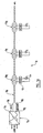
- a power distribution system 1a incorporates a twisted pair 2a which comprises a twisted pair of elongate conductors 3a,4a.
- the conductors 3a,4a are formed from a single loop of insulated wire which is folded in half and twisted to form the twisted pair 2a.
- the free ends 5a,6a of the conductors 3a,4a are positioned adjacent one another and connected to a high frequency AC power source 7a.
- the high frequency AC power source 7a preferably converts mains electricity at 110V or 240V AC at a frequency of 50Hz or 60Hz to high frequency AC power at approximately 1.34A at approximately 50kHz.
- the high frequency AC power source is current limited.
- the high frequency AC power source preferably provides a voltage of between 150V and 1 kV, at an operating frequency of greater than 10kHz, but most preferably at a frequency of 60kHz.
- the loop defined by the twisted pair 2a equates to turns of a transformer coil which is connected to the high frequency AC power source 7a.
- the power distribution system 1a incorporates a power tapping element 8a which is a splittable ferrite element.
- Identical second and third power tapping elements 9a,10a are shown in figure 1 but it is to be appreciated that the preferred embodiment of the invention incorporates just one power tapping element 8a.
- the power tapping element 8a is of a ferrous material.
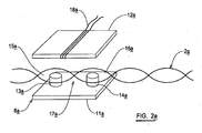
- the power tapping element 8a comprises a rectangular planar base 11a and an identical rectangular planar top plate 12a.
- Two spaced apart upstanding cylindrical ferrite members 13a,14a are mounted to the top of the base 11a.
- the tops of the ferrite members 13a,14a are configured to engage and attach to the underside of the top plate 12a so that the ferrite members 13a,14a are sandwiched between the base 11a and the top plate 12a when the power tapping element 8a is assembled.
- the top plate 12a is removably attachable to the ferrite members 13a,14a to allow the top plate 12a to be removed, as shown in figure 2a .
- the power tapping element 8a is attached to the twisted pair 2a by pushing the ferrite members 13a,14a between adjacent turns of the twisted pair 2a.
- the conductors 3a,4a between adjacent turns of the twisted pair 2a are thus moved apart from one another to define an aperture therebetween which receives at least part of the power tapping element 8a.
- the top plate 12a is attached to the ferrite members 13a,14a to attach the power tapping element 8a to the twisted pair 2a.
- the power tapping element 8a forms the core of a transformer and the loops of the twisted pair 2a which pass around the ferrite elements 13a,14a form a primary coil 17a of the transformer.
- a further conductor 18a is wound around the power tapping element 8a, preferably around the top plate 12a.
- the further conductor defines a secondary coil of the transformer.
- the power tapping element 8a therefore allows high frequency AC power to be tapped off the twisted pair 2a, into the further conductor 18a.
- the further conductor 18a is preferably connected to an AC-DC converter 19a which converts the high frequency AC power into a DC voltage to supply a constant current load, such as an LED D1 a or an OLED.
- the AC-DC converter is preferably a synchronous converter of a type which will be discussed below.
- Power can be tapped off from the twisted pair 2a by a power tapping element at any point along the twisted pair 2a without breaking the conductors 3a,4a or breaching the insulation of the conductors 3a,4a.
- the power distribution system provides a contactless connection to a load. It is thus easy to couple power from the twisted pair 2a to a load D1 a at any point along the length of the twisted pair 2a.
- the twisting of the conductors 3a,4a in the twisted pair 2a results in the electric field of one conductor 3a cancelling the electric field of the other conductor 4a which minimises electromagnetic radiation (EMI) being emitted from the system 1a.
- EMI electromagnetic radiation
- the balanced take-off of power provided by the power tapping element 8a minimises the electric field.
- the coupling efficiency between the twisted pair and the AC-DC converter 19a is greater than 97%.
- the transformer formed by the power tapping element 8a and the turns of the twisted pair 2a and the further conductor 18a form a very small transformer which is approximately 10cm 3 in volume. Despite the small size, the transformer has a power rating of 15W.
- the power tapping arrangement of the power distribution system 1a is very cost effective because it performs a transformer and connector function in one unit.
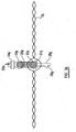
- the power tapping element is a splittable ferrite element 20a, as shown in figure 3a .
- one ferrite member 21a of the ferrite element 20a passes through an opening 22a in the twisted pair 2a, rather than two ferrite members 13a,15a passing through two openings 15a,16a in the twisted pair 2a as described above.
- the loop of the conductors 3a,4a which extends around the ferrite member 21a forms one turn of a primary coil of the power tap-off transformer.
- a further conductor 23a is wound around the ferrite element 20a to couple power to an AC-DC converter 24a which in turn powers a load D2a.
- a shorting loop conductor 25a is wound around the ferrite member 20a.
- a shorting switch 26a is provided in series with the shorting loop 25a. When the shorting switch 26a is open, the shorting loop 25a has no inductive effect and power is coupled from the twisted pair 2a to the load circuit. When the shorting switch 26a is closed, the shorting loop 25a prevents power from being coupled inductively via the ferrite member 20a to the load circuit, thereby switching off the load circuit. When the load circuit is switched off using the shorting loop 25a and the shorting switch 26a, there is negligible energy loss from the twisted pair 2a since no power is coupled inductively from the twisted pair 2a to the load circuit.
- the shorting switch 26a is an electronic switch which draws power from its own inductive coupling to a loop of the twisted pair 2a.
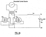
- a synchronous rectifier circuit for use as an AC-DC converter in embodiments of the invention incorporates a first MOSFET switch Q1a and a second MOSFET switch Q2a.
- the drains of the switches Q1a and Q2a are connected respectively to each end of a secondary coil of a transformer TX.
- the primary winding of the transformer TX equates to loops of the twisted pair 2a which are connected to a high frequency, high impedance, AC power source which alternates with a limited rate of change of current.
- the drains of the switches Q1a and Q2a are connected respectively to each end of a secondary coil of a transformer TX.
- the secondary winding of the transformer TX equates to the further conductor 18a in the power distribution arrangement 1a.
- the core of the transformer TX equates to the power tapping member 8a.
- the minimum rate of change of current of the high impedance power source is twice the peak to peak amplitude of the current divided by the period of the current wave. This is equivalent to the slope of a triangular wave.
- the maximum rate of change of current of the high impedance power source is ten times the peak to peak amplitude of the current divided by the period of the current wave. This is equivalent to a square wave with transitions taking 10% of its total period.
- the high frequency AC power source preferably provides a voltage of between 150V and 1 kV, at an operating frequency of greater than 10kHz, but most preferably at a frequency of 60kHz.
- the gate terminal of the first switch Q1a is connected to the drain terminal of the second switch Q2a.
- the gate terminal of the second switch Q2a is connected to the drain terminal of the first switch Q1a.
- the source terminals of the switches Q1a and Q2a are connected to one another and to a low voltage rail 0V which defines one output terminal.
- One terminal of an inductor La is connected to a centre tap of the secondary coil of the transformer TX.
- the other terminal of the inductor La defines a positive DC voltage output rail Vo.
- a load D 1 a in the form of an LED is connected between the output terminals Vo and 0V.
- the power supply 3a outputs a constant current to the load D 1 a.
- the load D 1 a limits the output voltage Vo such that the control voltage which drives the gates of the switches Q1a,Q2a is maintained within a suitable range for the switches Q1a,Q2a, for instance less than 10-15V.
- the power supply 3a does not require a drive circuit because the gate of each switch Q1a,Q2a is driven by the drain of the other switch Q1a,Q2a.
- the power supply 3a does not incorporate current sense resistors. These expensive and inefficient components are thus eliminated.
- the power supply 3a is therefore more efficient than conventional synchronous rectification power supplies which require deadband operation.
- Cross-conduction within the switches Q1a and Q2a is limited to only very small currents which further improves the efficiency of the power supply 3a.
- Body diode conduction within the switches Q1a and Q2a is kept to a minimum which minimises energy loss since only very small currents are able to flow by body diode conduction within the switches Q1a and Q2a.
- a modified synchronous rectifier circuit incorporates switches Q1a,Q2a with gates which are driven respectively by OR gate logic.
- One input of each OR gate is connected to a respective end of a secondary winding TXS1 which is one of the two windings of the twisted pair 2a that surrounds one of the ferrite members 13a,14a of the power tapping element 8a.
- the other input of each OR gate is connected to a switch.
- the switch provides an ON/OF toggle which can short out the secondary winding of the transformer TX. This allows the load to be switched on and off at zero crossing which reduces electrical disturbances along the twisted pair 2a.
- the coupling transformer formed by the power tap off arrangement in embodiments of the invention can match to any required load current.
- Each load along the power distribution system 1a can be controlled independently by simply shorting out the inductive power tap off, for instance using rectifiers, as shown in figure 5a .
- the power distribution system can be used to create a single power supply with multiple different regulated loads. This is an improvement over conventional approaches where many switching inverters are required to provide power to the different regulated loads.
- the power distribution system 1a can be used to provide power to many different designs of LED luminaire which output different coloured light or different beam patterns.
- the power distribution system 1a is capable of providing power to luminaires which have a large number of LEDs or OLEDs, whilst still preserving the low voltage classification and/or fault tolerance.
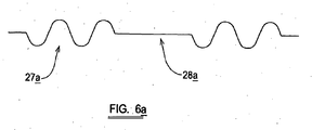
- the power distribution system 1a can incorporate a pulse density modulation (PDM) arrangement to modulate a current waveform 27a to drop pulses over a period of time 28a, as shown in figure 6a .
- PDM can be used to dim LEDs or OLEDs connected to the power distribution system 1.
- the PDM arrangement allows 250 steps of brightness for a 200Hz LED flicker rate.
- the current loop power in the twisted pair 2a can be distributed over many LED luminaires positioned along the length of the loop.
- Connecting transformer coupled loads in series can share a single current loop power supply.
- a constant current loop is indifferent to loop voltage drops. Load currents remain regulated by the loop current.
- the brightness of each luminaire remains constant for a large area without the need for local regulation.
Landscapes
- Circuit Arrangement For Electric Light Sources In General (AREA)
- Rectifiers (AREA)
- Electroluminescent Light Sources (AREA)
- Arrangement Of Elements, Cooling, Sealing, Or The Like Of Lighting Devices (AREA)
- Non-Portable Lighting Devices Or Systems Thereof (AREA)
- Dc-Dc Converters (AREA)
Priority Applications (1)
| Application Number | Priority Date | Filing Date | Title |
|---|---|---|---|
| PL10714355T PL2409548T3 (pl) | 2009-03-19 | 2010-03-19 | Układ elektryczny wykorzystujący prąd przemienny wysokiej częstotliwości, z podłączonymi indukcyjnie odbiornikami i odpowiednimi zasilaczami i oprawami oświetleniowymi |
Applications Claiming Priority (5)
| Application Number | Priority Date | Filing Date | Title |
|---|---|---|---|
| GB0904728A GB0904728D0 (en) | 2009-03-19 | 2009-03-19 | A luminaire |
| GB0904719A GB0904719D0 (en) | 2009-03-19 | 2009-03-19 | A power supply |
| GB0908208A GB0908208D0 (en) | 2009-05-13 | 2009-05-13 | A power distribution system |
| GB0908207A GB0908207D0 (en) | 2009-05-13 | 2009-05-13 | A power supply |
| PCT/GB2010/050472 WO2010106375A2 (en) | 2009-03-19 | 2010-03-19 | Electrical systems |
Publications (2)
| Publication Number | Publication Date |
|---|---|
| EP2409548A2 EP2409548A2 (en) | 2012-01-25 |
| EP2409548B1 true EP2409548B1 (en) | 2018-02-21 |
Family
ID=42199215
Family Applications (1)
| Application Number | Title | Priority Date | Filing Date |
|---|---|---|---|
| EP10714355.4A Active EP2409548B1 (en) | 2009-03-19 | 2010-03-19 | Electrical system using high frequency ac and having inductively connected loads, and corresponding power supplies and luminaires |
Country Status (10)
| Country | Link |
|---|---|
| US (1) | US9107259B2 (enExample) |
| EP (1) | EP2409548B1 (enExample) |
| JP (1) | JP5650713B2 (enExample) |
| CA (1) | CA2790890C (enExample) |
| DK (1) | DK2409548T3 (enExample) |
| ES (1) | ES2667949T3 (enExample) |
| HU (1) | HUE038293T2 (enExample) |
| PL (1) | PL2409548T3 (enExample) |
| PT (1) | PT2409548T (enExample) |
| WO (1) | WO2010106375A2 (enExample) |
Families Citing this family (38)
| Publication number | Priority date | Publication date | Assignee | Title |
|---|---|---|---|---|
| US9198237B2 (en) | 2004-02-25 | 2015-11-24 | Lynk Labs, Inc. | LED lighting system |
| US10154551B2 (en) | 2004-02-25 | 2018-12-11 | Lynk Labs, Inc. | AC light emitting diode and AC LED drive methods and apparatus |
| US10091842B2 (en) | 2004-02-25 | 2018-10-02 | Lynk Labs, Inc. | AC light emitting diode and AC LED drive methods and apparatus |
| US10506674B2 (en) | 2004-02-25 | 2019-12-10 | Lynk Labs, Inc. | AC light emitting diode and AC LED drive methods and apparatus |
| US10499465B2 (en) | 2004-02-25 | 2019-12-03 | Lynk Labs, Inc. | High frequency multi-voltage and multi-brightness LED lighting devices and systems and methods of using same |
| US10575376B2 (en) | 2004-02-25 | 2020-02-25 | Lynk Labs, Inc. | AC light emitting diode and AC LED drive methods and apparatus |
| US12279345B2 (en) | 2009-12-28 | 2025-04-15 | Lynk Labs, Inc. | Light emitting diode and LED drive apparatus |
| TW201132222A (en) | 2009-12-28 | 2011-09-16 | Lynk Labs Inc | High frequency multi-voltage and multi-brightness LED lighting devices and systems and methods of using same |
| KR20110108596A (ko) * | 2010-03-29 | 2011-10-06 | 삼성전자주식회사 | 전력 수신장치 및 무선전력 송수신시스템 |
| KR101623838B1 (ko) * | 2010-03-29 | 2016-06-07 | 삼성전자주식회사 | 전력 수신장치 및 무선전력 전송시스템 |
| CN101909394B (zh) * | 2010-09-02 | 2015-06-03 | Bcd半导体制造有限公司 | 一种调光的led灯驱动电路和方法 |
| JP5671940B2 (ja) * | 2010-10-28 | 2015-02-18 | 三菱電機株式会社 | 点灯装置ならびにこの点灯装置を備える照明器具 |
| US9247597B2 (en) | 2011-12-02 | 2016-01-26 | Lynk Labs, Inc. | Color temperature controlled and low THD LED lighting devices and systems and methods of driving the same |
| GB201120955D0 (en) | 2011-12-06 | 2012-01-18 | Isotera Ltd | A coupler for use in a power distribution system |
| JP6088234B2 (ja) * | 2011-12-23 | 2017-03-01 | 株式会社半導体エネルギー研究所 | 受電装置、無線給電システム |
| DE102012007478B4 (de) | 2012-04-13 | 2023-08-03 | Tridonic Gmbh & Co Kg | Wandler für ein Leuchtmittel, LED-Konverter und Verfahren zum Betreiben eines Wandlers |
| US8926133B2 (en) | 2012-09-13 | 2015-01-06 | Lumastream, Inc. | System, method, and apparatus for dissipating heat from a LED |
| US10290419B2 (en) | 2012-11-15 | 2019-05-14 | Hunza Holdings Limited | Power supply systems |
| DE102012224212B4 (de) * | 2012-12-21 | 2023-05-04 | Tridonic Gmbh & Co Kg | Primärseitig gesteuerter Konstantstrom-Konverter für Beleuchtungseinrichtungen |
| KR20150130978A (ko) | 2013-02-11 | 2015-11-24 | 그라코 미네소타 인크. | 유체 도포기 시스템을 위한 원격 모니터링 |
| US9380654B2 (en) * | 2013-07-11 | 2016-06-28 | General Electric Company | Light emitting diode (LED) lamp replacement driver for linear fluorescent lamps |
| US9380660B2 (en) * | 2013-08-07 | 2016-06-28 | Panasonic Intellectual Property Management Co., Ltd. | Electronic ballast and luminaire with the same |
| AT14739U1 (de) * | 2013-08-19 | 2016-05-15 | Tridonic Gmbh & Co Kg | Primärseitig gesteuerter Konstantstrom-Konverter für Beleuchtungseinrichtungen |
| GB2520037B (en) * | 2013-11-07 | 2021-08-11 | Greengage Lighting Ltd | Power distribution |
| US20150163874A1 (en) * | 2013-12-11 | 2015-06-11 | General Electric Company | Multi-mode controller circuit |
| GB201322022D0 (en) * | 2013-12-12 | 2014-01-29 | Led Lighting Consultants Ltd | Improvements relating to power adaptors |
| AT14262U1 (de) * | 2014-01-13 | 2015-07-15 | Tridonic Gmbh & Co Kg | Treiberschaltung für Leuchtmittel, insbesondere LEDs |
| AT14343U1 (de) * | 2014-03-31 | 2015-09-15 | Tridonic Gmbh & Co Kg | Betriebsgerät, Leuchte und Verfahren zum Betreiben eines Leuchtmittels |
| EP3150026B1 (en) * | 2014-05-30 | 2020-11-11 | Signify Holding B.V. | Led driver circuit, led circuit and drive method |
| EP3172944A2 (en) * | 2014-07-22 | 2017-05-31 | Philips Lighting Holding B.V. | Signal carrier for contactless lighting system and lighting system including signal carrier |
| JP6588531B2 (ja) * | 2014-08-07 | 2019-10-09 | シグニファイ ホールディング ビー ヴィ | ドライバ装置及び駆動方法 |
| CN108240613B (zh) * | 2016-12-23 | 2021-10-26 | 首尔半导体股份有限公司 | Led驱动用系统级封装及含其的led照明装置 |
| CN107785985B (zh) * | 2017-11-09 | 2020-06-26 | 黎辉 | 一种高低频复合式供电装置 |
| US10985555B2 (en) * | 2018-09-11 | 2021-04-20 | Valve Corporation | Systems and methods for long reach high efficiency power distribution |
| US11418125B2 (en) | 2019-10-25 | 2022-08-16 | The Research Foundation For The State University Of New York | Three phase bidirectional AC-DC converter with bipolar voltage fed resonant stages |
| EP4189824A1 (en) | 2020-07-31 | 2023-06-07 | Energy Research Lab Ltd | An inverter |
| GB2600492B (en) | 2020-11-03 | 2023-11-29 | Energy Res Lab Ltd | Power supply apparatus |
| GB202318526D0 (en) * | 2023-12-04 | 2024-01-17 | Energy Res Lab Ltd | High frequency AC-DC converter |
Family Cites Families (22)
| Publication number | Priority date | Publication date | Assignee | Title |
|---|---|---|---|---|
| US3787752A (en) | 1972-07-28 | 1974-01-22 | Us Navy | Intensity control for light-emitting diode display |
| US4264827A (en) * | 1978-11-06 | 1981-04-28 | The Boeing Company | Current mode data or power bus |
| US5998936A (en) * | 1984-01-09 | 1999-12-07 | Nilssen; Ole K. | Fire-initiation-safe lighting system |
| EP0587923A1 (en) | 1992-09-14 | 1994-03-23 | U.R.D. Co. Ltd. | High-frequency constant-current feeding system |
| JPH0787691A (ja) * | 1993-09-14 | 1995-03-31 | Matsushita Electric Works Ltd | 無結線給電システム |
| JPH07337005A (ja) * | 1994-06-03 | 1995-12-22 | Hitachi Ltd | Dc/dcコンバータおよび電源装置 |
| DE69535873D1 (de) * | 1994-07-13 | 2008-12-04 | Auckland Uniservices Ltd | Induktiv gespeiste Beleuchtung |
| DE69605530T2 (de) * | 1995-09-25 | 2000-07-20 | Koninklijke Philips Electronics N.V., Eindhoven | Leistungsversorgungsschaltung mit einem transformator und einem schalter auf der sekundärseite des transformators |
| US6188179B1 (en) * | 1995-10-24 | 2001-02-13 | Auckland Uniservices Limited | Induction circuits for lighting |
| US6172466B1 (en) | 1999-02-12 | 2001-01-09 | The Hong Kong University Of Science And Technology | Phase-controlled dimmable ballast |
| US6271633B1 (en) * | 1999-11-01 | 2001-08-07 | Philips Electronics North America Corporation | High power factor electronic ballast with fully differential circuit topology |
| US6301139B1 (en) * | 2000-04-06 | 2001-10-09 | Power-One, Inc. | Self-driven synchronous rectifier circuit for non-optimal reset secondary voltage |
| US6563719B1 (en) * | 2002-04-09 | 2003-05-13 | Bel-Fuse, Inc. | Self-driven synchronous rectification scheme |
| US7646279B2 (en) * | 2003-05-02 | 2010-01-12 | Limpkin George A | Apparatus for supplying energy to a load and a related system |
| JP2005174725A (ja) * | 2003-12-11 | 2005-06-30 | Matsushita Electric Works Ltd | 発光ダイオードの点灯回路ならびにそれを用いる照明ユニットおよび調光システム |
| IES20050086A2 (en) | 2004-02-17 | 2005-09-21 | William M Kelly | A utility lamp |
| US7082043B2 (en) * | 2004-03-16 | 2006-07-25 | Tyco Electronics Power Systems, Inc. | Drive circuit for a synchronous rectifier, method of providing drive signals thereto and power converter incorporating the same |
| US7646029B2 (en) * | 2004-07-08 | 2010-01-12 | Philips Solid-State Lighting Solutions, Inc. | LED package methods and systems |
| US7658510B2 (en) | 2004-08-18 | 2010-02-09 | Remco Solid State Lighting Inc. | System and method for power control in a LED luminaire |
| DE602005006587D1 (de) * | 2005-11-22 | 2008-06-19 | Patent Treuhand Ges Fuer Elektrische Gluehlampen Mbh | Antriebsvorrichtung für LED-zellen |
| US7928664B2 (en) * | 2006-04-10 | 2011-04-19 | Emd Technologies, Inc. | Illumination systems |
| US8942018B2 (en) * | 2008-08-20 | 2015-01-27 | ConvenientPower HK Ltd. | Single-phase self-driven full-bridge synchronous rectification |
-
2010
- 2010-03-19 CA CA2790890A patent/CA2790890C/en active Active
- 2010-03-19 WO PCT/GB2010/050472 patent/WO2010106375A2/en not_active Ceased
- 2010-03-19 EP EP10714355.4A patent/EP2409548B1/en active Active
- 2010-03-19 US US13/256,946 patent/US9107259B2/en active Active
- 2010-03-19 ES ES10714355.4T patent/ES2667949T3/es active Active
- 2010-03-19 HU HUE10714355A patent/HUE038293T2/hu unknown
- 2010-03-19 PL PL10714355T patent/PL2409548T3/pl unknown
- 2010-03-19 JP JP2012500321A patent/JP5650713B2/ja active Active
- 2010-03-19 DK DK10714355.4T patent/DK2409548T3/en active
- 2010-03-19 PT PT107143554T patent/PT2409548T/pt unknown
Also Published As
| Publication number | Publication date |
|---|---|
| US20120001563A1 (en) | 2012-01-05 |
| PT2409548T (pt) | 2018-05-09 |
| WO2010106375A2 (en) | 2010-09-23 |
| JP5650713B2 (ja) | 2015-01-07 |
| CA2790890C (en) | 2019-05-21 |
| JP2012521085A (ja) | 2012-09-10 |
| WO2010106375A3 (en) | 2010-12-02 |
| DK2409548T3 (en) | 2018-05-22 |
| ES2667949T3 (es) | 2018-05-16 |
| US9107259B2 (en) | 2015-08-11 |
| PL2409548T3 (pl) | 2018-07-31 |
| HUE038293T2 (hu) | 2018-10-29 |
| EP2409548A2 (en) | 2012-01-25 |
| CA2790890A1 (en) | 2010-09-23 |
Similar Documents
| Publication | Publication Date | Title |
|---|---|---|
| EP2409548B1 (en) | Electrical system using high frequency ac and having inductively connected loads, and corresponding power supplies and luminaires | |
| US7609007B1 (en) | Dimmer adaptable to either two or three active wires | |
| JP6294824B2 (ja) | 太陽光発電システム用dc−acインバータ | |
| JP5493245B2 (ja) | エネルギーを負荷及び関連システムへ供給するための装置 | |
| EP2477459A1 (en) | Hybrid control system | |
| WO2002093655A1 (en) | Apparatus for generating photovoltaic energy | |
| JP2012521085A5 (enExample) | ||
| US10433379B2 (en) | Power distribution | |
| RU2011100177A (ru) | Установка для передачи электрической энергии | |
| CN107733095B (zh) | 一种桌面无线供电系统及供电控制方法 | |
| US20160164343A1 (en) | Power Transmission Device | |
| US9712069B2 (en) | Distributed-constant type transformer for voltage conversion | |
| US20140204614A1 (en) | Rectified high frequency power supply with low total harmonic distortion (thd) | |
| RU2749609C2 (ru) | Система электропитания | |
| EP2929616B1 (en) | Improvements in and relating to power supply systems | |
| CN101728955A (zh) | 用于电能表的隔离rs485电源电路及其脉冲变压器 | |
| US20110085362A1 (en) | Drive unit, for instance for halogen lamps, and corresponding method | |
| CN112152328B (zh) | 单线供电与信号传输装置 | |
| Schmitt et al. | Power supply for a IGBT-driver with high insulation voltage based on a printed planar transformers | |
| RU114236U1 (ru) | Интегрированная система передачи электрической энергии и данных на основе оптоволоконного кабеля связи | |
| HK40037889A (en) | Power distribution | |
| SE1100309A1 (sv) | Transformer arrangement for high voltage applications | |
| HK40009555B (zh) | 电力分配系统 | |
| Denicholas | Dimming | |
| GB2414607A (en) | Power supply with inductive coupling |
Legal Events
| Date | Code | Title | Description |
|---|---|---|---|
| PUAI | Public reference made under article 153(3) epc to a published international application that has entered the european phase |
Free format text: ORIGINAL CODE: 0009012 |
|
| 17P | Request for examination filed |
Effective date: 20111012 |
|
| AK | Designated contracting states |
Kind code of ref document: A2 Designated state(s): AT BE BG CH CY CZ DE DK EE ES FI FR GB GR HR HU IE IS IT LI LT LU LV MC MK MT NL NO PL PT RO SE SI SK SM TR |
|
| DAX | Request for extension of the european patent (deleted) | ||
| RAP1 | Party data changed (applicant data changed or rights of an application transferred) |
Owner name: ISOTERA LIMITED |
|
| GRAP | Despatch of communication of intention to grant a patent |
Free format text: ORIGINAL CODE: EPIDOSNIGR1 |
|
| INTG | Intention to grant announced |
Effective date: 20160707 |
|
| GRAJ | Information related to disapproval of communication of intention to grant by the applicant or resumption of examination proceedings by the epo deleted |
Free format text: ORIGINAL CODE: EPIDOSDIGR1 |
|
| GRAP | Despatch of communication of intention to grant a patent |
Free format text: ORIGINAL CODE: EPIDOSNIGR1 |
|
| INTC | Intention to grant announced (deleted) | ||
| INTG | Intention to grant announced |
Effective date: 20161216 |
|
| GRAS | Grant fee paid |
Free format text: ORIGINAL CODE: EPIDOSNIGR3 |
|
| 19U | Interruption of proceedings before grant |
Effective date: 20170801 |
|
| 19W | Proceedings resumed before grant after interruption of proceedings |
Effective date: 20180102 |
|
| GRAA | (expected) grant |
Free format text: ORIGINAL CODE: 0009210 |
|
| RAP1 | Party data changed (applicant data changed or rights of an application transferred) |
Owner name: GREENGAGE LIGHTING LIMITED |
|
| AK | Designated contracting states |
Kind code of ref document: B1 Designated state(s): AT BE BG CH CY CZ DE DK EE ES FI FR GB GR HR HU IE IS IT LI LT LU LV MC MK MT NL NO PL PT RO SE SI SK SM TR |
|
| REG | Reference to a national code |
Ref country code: GB Ref legal event code: FG4D |
|
| REG | Reference to a national code |
Ref country code: CH Ref legal event code: EP |
|
| REG | Reference to a national code |
Ref country code: DE Ref legal event code: R096 Ref document number: 602010048606 Country of ref document: DE Ref country code: AT Ref legal event code: REF Ref document number: 973074 Country of ref document: AT Kind code of ref document: T Effective date: 20180315 |
|
| REG | Reference to a national code |
Ref country code: IE Ref legal event code: FG4D |
|
| REG | Reference to a national code |
Ref country code: FR Ref legal event code: PLFP Year of fee payment: 9 |
|
| REG | Reference to a national code |
Ref country code: RO Ref legal event code: EPE |
|
| REG | Reference to a national code |
Ref country code: PT Ref legal event code: SC4A Ref document number: 2409548 Country of ref document: PT Date of ref document: 20180509 Kind code of ref document: T Free format text: AVAILABILITY OF NATIONAL TRANSLATION Effective date: 20180502 |
|
| REG | Reference to a national code |
Ref country code: CH Ref legal event code: NV Representative=s name: MICHELI AND CIE SA, CH |
|
| REG | Reference to a national code |
Ref country code: ES Ref legal event code: FG2A Ref document number: 2667949 Country of ref document: ES Kind code of ref document: T3 Effective date: 20180516 Ref country code: NL Ref legal event code: FP |
|
| REG | Reference to a national code |
Ref country code: DK Ref legal event code: T3 Effective date: 20180516 Ref country code: SE Ref legal event code: TRGR |
|
| REG | Reference to a national code |
Ref country code: LT Ref legal event code: MG4D |
|
| PG25 | Lapsed in a contracting state [announced via postgrant information from national office to epo] |
Ref country code: FI Free format text: LAPSE BECAUSE OF FAILURE TO SUBMIT A TRANSLATION OF THE DESCRIPTION OR TO PAY THE FEE WITHIN THE PRESCRIBED TIME-LIMIT Effective date: 20180221 Ref country code: NO Free format text: LAPSE BECAUSE OF FAILURE TO SUBMIT A TRANSLATION OF THE DESCRIPTION OR TO PAY THE FEE WITHIN THE PRESCRIBED TIME-LIMIT Effective date: 20180521 Ref country code: CY Free format text: LAPSE BECAUSE OF FAILURE TO SUBMIT A TRANSLATION OF THE DESCRIPTION OR TO PAY THE FEE WITHIN THE PRESCRIBED TIME-LIMIT Effective date: 20180221 Ref country code: HR Free format text: LAPSE BECAUSE OF FAILURE TO SUBMIT A TRANSLATION OF THE DESCRIPTION OR TO PAY THE FEE WITHIN THE PRESCRIBED TIME-LIMIT Effective date: 20180221 Ref country code: LT Free format text: LAPSE BECAUSE OF FAILURE TO SUBMIT A TRANSLATION OF THE DESCRIPTION OR TO PAY THE FEE WITHIN THE PRESCRIBED TIME-LIMIT Effective date: 20180221 |
|
| PG25 | Lapsed in a contracting state [announced via postgrant information from national office to epo] |
Ref country code: LV Free format text: LAPSE BECAUSE OF FAILURE TO SUBMIT A TRANSLATION OF THE DESCRIPTION OR TO PAY THE FEE WITHIN THE PRESCRIBED TIME-LIMIT Effective date: 20180221 Ref country code: BG Free format text: LAPSE BECAUSE OF FAILURE TO SUBMIT A TRANSLATION OF THE DESCRIPTION OR TO PAY THE FEE WITHIN THE PRESCRIBED TIME-LIMIT Effective date: 20180521 |
|
| REG | Reference to a national code |
Ref country code: HU Ref legal event code: AG4A Ref document number: E038293 Country of ref document: HU |
|
| PG25 | Lapsed in a contracting state [announced via postgrant information from national office to epo] |
Ref country code: EE Free format text: LAPSE BECAUSE OF FAILURE TO SUBMIT A TRANSLATION OF THE DESCRIPTION OR TO PAY THE FEE WITHIN THE PRESCRIBED TIME-LIMIT Effective date: 20180221 |
|
| REG | Reference to a national code |
Ref country code: GR Ref legal event code: EP Ref document number: 20180401190 Country of ref document: GR Effective date: 20181012 |
|
| REG | Reference to a national code |
Ref country code: DE Ref legal event code: R097 Ref document number: 602010048606 Country of ref document: DE |
|
| PG25 | Lapsed in a contracting state [announced via postgrant information from national office to epo] |
Ref country code: SK Free format text: LAPSE BECAUSE OF FAILURE TO SUBMIT A TRANSLATION OF THE DESCRIPTION OR TO PAY THE FEE WITHIN THE PRESCRIBED TIME-LIMIT Effective date: 20180221 Ref country code: MC Free format text: LAPSE BECAUSE OF FAILURE TO SUBMIT A TRANSLATION OF THE DESCRIPTION OR TO PAY THE FEE WITHIN THE PRESCRIBED TIME-LIMIT Effective date: 20180221 Ref country code: SM Free format text: LAPSE BECAUSE OF FAILURE TO SUBMIT A TRANSLATION OF THE DESCRIPTION OR TO PAY THE FEE WITHIN THE PRESCRIBED TIME-LIMIT Effective date: 20180221 |
|
| PLBE | No opposition filed within time limit |
Free format text: ORIGINAL CODE: 0009261 |
|
| STAA | Information on the status of an ep patent application or granted ep patent |
Free format text: STATUS: NO OPPOSITION FILED WITHIN TIME LIMIT |
|
| PG25 | Lapsed in a contracting state [announced via postgrant information from national office to epo] |
Ref country code: LU Free format text: LAPSE BECAUSE OF NON-PAYMENT OF DUE FEES Effective date: 20180319 |
|
| 26N | No opposition filed |
Effective date: 20181122 |
|
| PG25 | Lapsed in a contracting state [announced via postgrant information from national office to epo] |
Ref country code: SI Free format text: LAPSE BECAUSE OF FAILURE TO SUBMIT A TRANSLATION OF THE DESCRIPTION OR TO PAY THE FEE WITHIN THE PRESCRIBED TIME-LIMIT Effective date: 20180221 |
|
| REG | Reference to a national code |
Ref country code: DE Ref legal event code: R079 Ref document number: 602010048606 Country of ref document: DE Free format text: PREVIOUS MAIN CLASS: H05B0033080000 Ipc: H05B0045000000 |
|
| PG25 | Lapsed in a contracting state [announced via postgrant information from national office to epo] |
Ref country code: MT Free format text: LAPSE BECAUSE OF NON-PAYMENT OF DUE FEES Effective date: 20180319 |
|
| PGFP | Annual fee paid to national office [announced via postgrant information from national office to epo] |
Ref country code: DK Payment date: 20200317 Year of fee payment: 11 Ref country code: HU Payment date: 20200225 Year of fee payment: 11 Ref country code: AT Payment date: 20200319 Year of fee payment: 11 Ref country code: SE Payment date: 20200317 Year of fee payment: 11 Ref country code: RO Payment date: 20200227 Year of fee payment: 11 Ref country code: GR Payment date: 20200319 Year of fee payment: 11 |
|
| PGFP | Annual fee paid to national office [announced via postgrant information from national office to epo] |
Ref country code: CZ Payment date: 20200228 Year of fee payment: 11 |
|
| PG25 | Lapsed in a contracting state [announced via postgrant information from national office to epo] |
Ref country code: MK Free format text: LAPSE BECAUSE OF NON-PAYMENT OF DUE FEES Effective date: 20180221 |
|
| REG | Reference to a national code |
Ref country code: AT Ref legal event code: UEP Ref document number: 973074 Country of ref document: AT Kind code of ref document: T Effective date: 20180221 |
|
| PG25 | Lapsed in a contracting state [announced via postgrant information from national office to epo] |
Ref country code: IS Free format text: LAPSE BECAUSE OF FAILURE TO SUBMIT A TRANSLATION OF THE DESCRIPTION OR TO PAY THE FEE WITHIN THE PRESCRIBED TIME-LIMIT Effective date: 20180621 |
|
| PG25 | Lapsed in a contracting state [announced via postgrant information from national office to epo] |
Ref country code: CZ Free format text: LAPSE BECAUSE OF NON-PAYMENT OF DUE FEES Effective date: 20210319 |
|
| REG | Reference to a national code |
Ref country code: DK Ref legal event code: EBP Effective date: 20210331 |
|
| REG | Reference to a national code |
Ref country code: AT Ref legal event code: MM01 Ref document number: 973074 Country of ref document: AT Kind code of ref document: T Effective date: 20210319 |
|
| PG25 | Lapsed in a contracting state [announced via postgrant information from national office to epo] |
Ref country code: RO Free format text: LAPSE BECAUSE OF NON-PAYMENT OF DUE FEES Effective date: 20210319 |
|
| PG25 | Lapsed in a contracting state [announced via postgrant information from national office to epo] |
Ref country code: AT Free format text: LAPSE BECAUSE OF NON-PAYMENT OF DUE FEES Effective date: 20210319 Ref country code: HU Free format text: LAPSE BECAUSE OF NON-PAYMENT OF DUE FEES Effective date: 20210320 Ref country code: SE Free format text: LAPSE BECAUSE OF NON-PAYMENT OF DUE FEES Effective date: 20210320 |
|
| PG25 | Lapsed in a contracting state [announced via postgrant information from national office to epo] |
Ref country code: GR Free format text: LAPSE BECAUSE OF NON-PAYMENT OF DUE FEES Effective date: 20211008 |
|
| PG25 | Lapsed in a contracting state [announced via postgrant information from national office to epo] |
Ref country code: DK Free format text: LAPSE BECAUSE OF NON-PAYMENT OF DUE FEES Effective date: 20210331 |
|
| PGFP | Annual fee paid to national office [announced via postgrant information from national office to epo] |
Ref country code: TR Payment date: 20230227 Year of fee payment: 14 Ref country code: PT Payment date: 20230301 Year of fee payment: 14 Ref country code: IT Payment date: 20230320 Year of fee payment: 14 Ref country code: BE Payment date: 20230315 Year of fee payment: 14 |
|
| P01 | Opt-out of the competence of the unified patent court (upc) registered |
Effective date: 20230519 |
|
| PGFP | Annual fee paid to national office [announced via postgrant information from national office to epo] |
Ref country code: NL Payment date: 20230316 Year of fee payment: 14 |
|
| PGFP | Annual fee paid to national office [announced via postgrant information from national office to epo] |
Ref country code: ES Payment date: 20230412 Year of fee payment: 14 |
|
| PG25 | Lapsed in a contracting state [announced via postgrant information from national office to epo] |
Ref country code: PT Free format text: LAPSE BECAUSE OF NON-PAYMENT OF DUE FEES Effective date: 20240919 |
|
| PG25 | Lapsed in a contracting state [announced via postgrant information from national office to epo] |
Ref country code: PT Free format text: LAPSE BECAUSE OF NON-PAYMENT OF DUE FEES Effective date: 20240919 |
|
| REG | Reference to a national code |
Ref country code: NL Ref legal event code: MM Effective date: 20240401 |
|
| PG25 | Lapsed in a contracting state [announced via postgrant information from national office to epo] |
Ref country code: NL Free format text: LAPSE BECAUSE OF NON-PAYMENT OF DUE FEES Effective date: 20240401 |
|
| REG | Reference to a national code |
Ref country code: BE Ref legal event code: MM Effective date: 20240331 |
|
| PG25 | Lapsed in a contracting state [announced via postgrant information from national office to epo] |
Ref country code: NL Free format text: LAPSE BECAUSE OF NON-PAYMENT OF DUE FEES Effective date: 20240401 |
|
| PG25 | Lapsed in a contracting state [announced via postgrant information from national office to epo] |
Ref country code: BE Free format text: LAPSE BECAUSE OF NON-PAYMENT OF DUE FEES Effective date: 20240331 |
|
| PG25 | Lapsed in a contracting state [announced via postgrant information from national office to epo] |
Ref country code: BE Free format text: LAPSE BECAUSE OF NON-PAYMENT OF DUE FEES Effective date: 20240331 |
|
| PG25 | Lapsed in a contracting state [announced via postgrant information from national office to epo] |
Ref country code: IT Free format text: LAPSE BECAUSE OF NON-PAYMENT OF DUE FEES Effective date: 20240319 |
|
| REG | Reference to a national code |
Ref country code: ES Ref legal event code: FD2A Effective date: 20250506 |
|
| PG25 | Lapsed in a contracting state [announced via postgrant information from national office to epo] |
Ref country code: ES Free format text: LAPSE BECAUSE OF NON-PAYMENT OF DUE FEES Effective date: 20240320 |
|
| REG | Reference to a national code |
Ref country code: DE Ref legal event code: R081 Ref document number: 602010048606 Country of ref document: DE Owner name: ROL-TECH-MAR SP.Z.O.O., PL Free format text: FORMER OWNER: GREENGAGE LIGHTING LIMITED, MANCHESTER, GB |
|
| PGFP | Annual fee paid to national office [announced via postgrant information from national office to epo] |
Ref country code: DE Payment date: 20250901 Year of fee payment: 16 |
|
| PGFP | Annual fee paid to national office [announced via postgrant information from national office to epo] |
Ref country code: PL Payment date: 20250901 Year of fee payment: 16 |
|
| PGFP | Annual fee paid to national office [announced via postgrant information from national office to epo] |
Ref country code: GB Payment date: 20250901 Year of fee payment: 16 |
|
| PGFP | Annual fee paid to national office [announced via postgrant information from national office to epo] |
Ref country code: FR Payment date: 20250901 Year of fee payment: 16 |
|
| PGFP | Annual fee paid to national office [announced via postgrant information from national office to epo] |
Ref country code: CH Payment date: 20250918 Year of fee payment: 16 |
|
| PGFP | Annual fee paid to national office [announced via postgrant information from national office to epo] |
Ref country code: IE Payment date: 20250916 Year of fee payment: 16 |