EP2407695A2 - Multifunktionelles Unterputzduschventil - Google Patents
Multifunktionelles Unterputzduschventil Download PDFInfo
- Publication number
- EP2407695A2 EP2407695A2 EP20110171922 EP11171922A EP2407695A2 EP 2407695 A2 EP2407695 A2 EP 2407695A2 EP 20110171922 EP20110171922 EP 20110171922 EP 11171922 A EP11171922 A EP 11171922A EP 2407695 A2 EP2407695 A2 EP 2407695A2
- Authority
- EP
- European Patent Office
- Prior art keywords
- water channel
- partition wall
- hole
- embedded body
- hot water
- Prior art date
- Legal status (The legal status is an assumption and is not a legal conclusion. Google has not performed a legal analysis and makes no representation as to the accuracy of the status listed.)
- Withdrawn
Links
- XLYOFNOQVPJJNP-UHFFFAOYSA-N water Substances O XLYOFNOQVPJJNP-UHFFFAOYSA-N 0.000 claims abstract description 74
- 238000005192 partition Methods 0.000 claims abstract description 34
- 230000008878 coupling Effects 0.000 claims description 24
- 238000010168 coupling process Methods 0.000 claims description 24
- 238000005859 coupling reaction Methods 0.000 claims description 24
- 238000007789 sealing Methods 0.000 claims description 16
- 230000003014 reinforcing effect Effects 0.000 claims description 3
- 238000005516 engineering process Methods 0.000 description 3
- 238000010586 diagram Methods 0.000 description 2
- 239000006185 dispersion Substances 0.000 description 2
- 239000012535 impurity Substances 0.000 description 2
- 230000000903 blocking effect Effects 0.000 description 1
- 230000003139 buffering effect Effects 0.000 description 1
- 230000007547 defect Effects 0.000 description 1
- 230000000694 effects Effects 0.000 description 1
- 238000009434 installation Methods 0.000 description 1
- 238000000034 method Methods 0.000 description 1
- 238000012856 packing Methods 0.000 description 1
- 238000004904 shortening Methods 0.000 description 1
- 239000007921 spray Substances 0.000 description 1
- 230000009466 transformation Effects 0.000 description 1
- 238000000844 transformation Methods 0.000 description 1
- 238000003911 water pollution Methods 0.000 description 1
Images

Classifications
-
- F—MECHANICAL ENGINEERING; LIGHTING; HEATING; WEAPONS; BLASTING
- F16—ENGINEERING ELEMENTS AND UNITS; GENERAL MEASURES FOR PRODUCING AND MAINTAINING EFFECTIVE FUNCTIONING OF MACHINES OR INSTALLATIONS; THERMAL INSULATION IN GENERAL
- F16K—VALVES; TAPS; COCKS; ACTUATING-FLOATS; DEVICES FOR VENTING OR AERATING
- F16K19/00—Arrangements of valves and flow lines specially adapted for mixing fluids
-
- F—MECHANICAL ENGINEERING; LIGHTING; HEATING; WEAPONS; BLASTING
- F16—ENGINEERING ELEMENTS AND UNITS; GENERAL MEASURES FOR PRODUCING AND MAINTAINING EFFECTIVE FUNCTIONING OF MACHINES OR INSTALLATIONS; THERMAL INSULATION IN GENERAL
- F16K—VALVES; TAPS; COCKS; ACTUATING-FLOATS; DEVICES FOR VENTING OR AERATING
- F16K27/00—Construction of housing; Use of materials therefor
- F16K27/12—Covers for housings
-
- Y—GENERAL TAGGING OF NEW TECHNOLOGICAL DEVELOPMENTS; GENERAL TAGGING OF CROSS-SECTIONAL TECHNOLOGIES SPANNING OVER SEVERAL SECTIONS OF THE IPC; TECHNICAL SUBJECTS COVERED BY FORMER USPC CROSS-REFERENCE ART COLLECTIONS [XRACs] AND DIGESTS
- Y10—TECHNICAL SUBJECTS COVERED BY FORMER USPC
- Y10T—TECHNICAL SUBJECTS COVERED BY FORMER US CLASSIFICATION
- Y10T137/00—Fluid handling
- Y10T137/6851—With casing, support, protector or static constructional installations
- Y10T137/6966—Static constructional installations
- Y10T137/6969—Buildings
- Y10T137/698—Wall
-
- Y—GENERAL TAGGING OF NEW TECHNOLOGICAL DEVELOPMENTS; GENERAL TAGGING OF CROSS-SECTIONAL TECHNOLOGIES SPANNING OVER SEVERAL SECTIONS OF THE IPC; TECHNICAL SUBJECTS COVERED BY FORMER USPC CROSS-REFERENCE ART COLLECTIONS [XRACs] AND DIGESTS
- Y10—TECHNICAL SUBJECTS COVERED BY FORMER USPC
- Y10T—TECHNICAL SUBJECTS COVERED BY FORMER US CLASSIFICATION
- Y10T137/00—Fluid handling
- Y10T137/8593—Systems
- Y10T137/87249—Multiple inlet with multiple outlet
-
- Y—GENERAL TAGGING OF NEW TECHNOLOGICAL DEVELOPMENTS; GENERAL TAGGING OF CROSS-SECTIONAL TECHNOLOGIES SPANNING OVER SEVERAL SECTIONS OF THE IPC; TECHNICAL SUBJECTS COVERED BY FORMER USPC CROSS-REFERENCE ART COLLECTIONS [XRACs] AND DIGESTS
- Y10—TECHNICAL SUBJECTS COVERED BY FORMER USPC
- Y10T—TECHNICAL SUBJECTS COVERED BY FORMER US CLASSIFICATION
- Y10T137/00—Fluid handling
- Y10T137/8593—Systems
- Y10T137/87571—Multiple inlet with single outlet
- Y10T137/87676—With flow control
-
- Y—GENERAL TAGGING OF NEW TECHNOLOGICAL DEVELOPMENTS; GENERAL TAGGING OF CROSS-SECTIONAL TECHNOLOGIES SPANNING OVER SEVERAL SECTIONS OF THE IPC; TECHNICAL SUBJECTS COVERED BY FORMER USPC CROSS-REFERENCE ART COLLECTIONS [XRACs] AND DIGESTS
- Y10—TECHNICAL SUBJECTS COVERED BY FORMER USPC
- Y10T—TECHNICAL SUBJECTS COVERED BY FORMER US CLASSIFICATION
- Y10T137/00—Fluid handling
- Y10T137/8593—Systems
- Y10T137/87917—Flow path with serial valves and/or closures
- Y10T137/88054—Direct response normally closed valve limits direction of flow
Definitions
- the present invention relates to a shower valve, especially a pressure-adjustable concealed shower valve.
- shower valves or taps used in bathroom have cold water and hot water separated.
- the flow of the cold water and the hot water is controlled by valve openness.
- the wider the valve is opened the bigger the water flow is.
- the narrower the valve is opened the smaller the flow is.
- Pressure will be generated when water flows out, exerting an impact on each valve.
- These valves are rigid and have no buffering function. When the valve is opened, the surge of water flow will impact the valve, thus shortening the service life of the valve. Since there is no buffer unit, when cold/hot water is adjusted, some water will flow back. For example, hot water may flow back to join the hot water behind, and may flow back to the location of the cold water pipe, causing partial pollution. Without a buffer unit, water at a high temperature sprays out from the tap at a high speed, which is unpredictable and can easily cause bums to a user. So it is dangerous in operation.
- China Intellectual Property Office published Patent No. CN201232801Y on May 6, 2009 which is related to an embedded unit of tap body including an embedded box and a lower body.
- the lower body is fixed in the embedded box.
- Two or more water pipelines are arranged. One end of the pipeline penetrates through the lateral wall of the embedded box. The other end forms a through hole on an upper surface of the lower body.
- this device is not provided with a buffer unit, so the high-pressure hot water will directly eject from the tap, which is unpredictable.
- the scope of water flow dispersion becomes narrower and narrower after the pressure has dropped, so a user needs to adjust the valve to control the scope of water flow dispersion.
- the rigid structure also causes backflow of the water.
- the present invention solves the defect of the prior technology wherein the shower valve is rigid and the water pipeline is not provided with a buffer unit.
- the prior technology easily causes imbalance of water pressure, and may cause instant pressure surge that impacts the valve and reduces the service life.
- the present invention provides a simple-structured multi-functional concealed shower valve that is provided with a buffer unit in the water pipeline to adjust and balance the water pressure, prevent instant pressure surge and thus extend the service life of the valve.
- the present invention also solves the problem in prior technology where the shower valve is rigid and without buffer device which may cause backflow of water when closing the water channel and cause pollution to the water that follows.
- the present invention provides a multi-functional concealed shower valve which is provided with a buffer unit in the water channel to avoid instant shutoff and water backflow.
- the present invention adopts the following technical solution.
- the present invention provides a multi-functional concealed shower valve, including a shell.
- the shell is provided with an embedded body with water channels.
- a cover board that communicates with the water channels is arranged on the surface of the embedded body.
- the embedded body is further provided with channels for hot water and cold water respectively.
- the hot water channel and the cold water channel are provided with a partition wall with a hole.
- the partition wall separates the water inlets and outlets of the hot water channel and the cold water channel.
- a buffer unit that can be opened and closed is arranged on the partition wall.
- the buffer unit contains a fixed adjustment screw and the corresponding booster spring and the central rod. The end of the central rod matches with the hole on the partition wall and can form an open or close structure.
- the partition wall separates the cold water channel and the hot water channel.
- a buffer unit is arranged on the partition wall, so that the water in the cold water channel and the hot water channel cannot flow directly from the inlet to the outlet, thus reducing water flow pressure and relieving surge of valve.
- the buffer unit can balance the pressure of the hot water channel and the cold water channel. When the pressure is different, the buffer unit can adjust water pressure, especially the instant pressure, automatically, when the water is opened, thus extending the service life of the valve, especially the concealed valve. After the service life of the valve is extended, it is not necessary to change the valve frequently, which makes the operation convenient.
- the adjustment screw can be preset to the buffer parameter in advance according to a customer's need.
- the central rod always seals the round hole on the partition wall under the pressure of the major spring, thus blocking the cold water channel and hot water channel. If there is a pressure, the partition wall can be put through by overcoming the pressure of the booster spring. This achieves the buffer effect.
- the pressure of the water flow is smaller than that of the booster spring, water will not flow out directly, thus protecting the user. Even though the pressure of instant water flow is too high, it can be partially absorbed by the booster spring, thus reducing the water flow pressure and alleviating the impact to the valve. When the valve is closed, an instant close will make the water pressure too high.
- the instant pressure surge easily causes water backflow.
- the pressure surge can be absorbed by the buffer unit which can reduce the water flow, prevent the pressure from getting too high, avoid backflow, and avoid water pollution.
- the embedded body is a structure of a cross shape.
- the front side is a flat plane.
- the hot water channel and the cold water channel are on the same straight line.
- Two water outlets are on the same straight line.
- the hole center deviates from the line of the hot water channel and the cold water channel.
- the buffer unit is arranged in the big hole.
- the flat plane cooperates with the cover board.
- the contact plane is smooth, which lowers the probability of leakage, and facilitates processing and positioning of the embedded body.
- the big hole on the plane is used to place the buffer unit.
- the plane of the embedded body facilitates positioning and processing of the big hole.
- the position of the big hole deviates from the connecting line of the cold water channel and the hot water channel, lessening the volume of the valve as much as possible.
- the hot water channel and the cold water channel are provided with sinks where the partition wall is located.
- the sinks are directly opposite to the big hole.
- the bottom of the sink is the same as the inlet of the cold water channel and the hot water channel.
- the sink is provided with a round hole connected with the outlets of the cold water channel and the hot water channel on the lateral side.
- the center of the round hole on the partition wall and the center of the big hole are on the same line.
- a sink is arranged to place the buffer unit and also to facilitate placing the partition wall.
- the partition wall separates the sink into two chambers, one chamber communicating with the water inlet and the other chamber communicating with the water outlet.
- the partition wall is arranged inside the sink, so it is not necessary to be concerned with the sealing problem of the buffer unit.
- the buffer unit also contains a coupling nut, the adjustment screw being connected with the thread of the coupling nut, the adjustment screw being provided with a compressed channel inside thereof, a booster spring being arranged inside the compressed channel, the adjustment screw and the coupling nut being connected by a rubber seal ring.
- the adjustment screw has already been adjusted before the valve is installed.
- the coupling nut is used to fix the adjustment screw so as to prevent the thread gap between the adjustment screw and the coupling unit from leaking water.
- the rubber ring at the thread also facilitates the installation of the booster spring and the central rod. After being installed, the rubber ring is connected with the coupling nut to form a complete buffer unit.
- the embedded body has screw threads along the edge of the inner side of the big hole.
- the coupling nut has external threads through which the coupling nut is connected to the big hole.
- the coupling nut is fixed on the big hole of the embedded body through the external threads, thus facilitating determination of expansion of the central rod.
- the central rod is in the shape of "T".
- the vertical part of the central rod supports the booster spring and compresses the spring into the compressed channel.
- a sealing component with a wedge barb is arranged at the center of the straight part of the central rod.
- the casing of the sealing component is provided with a rubber ring. The barb limits the rubber ring.
- the sealing component is inserted into the round hole on the partition wall.
- the rubber ring seals the round hole.
- the sealing component as well as the rubber ring blocks the round hole on the partition wall.
- the sealing component will be opened only when the elasticity of the booster spring drops, the round hole is blocked, and the water pressure has reached a specific value, thus opening the water channel.
- the barb can prevent the rubber ring from escaping from the sealing component.
- the shell is a circular shape.
- the lateral wall of the shell is provided with four coupling holes communicated with water channels of the embedded body.
- the end of the water channel is provided with a lock nut.
- the embedded body is fixed on the coupling hole by the lock nut.
- the quantity of the connecting holes on the shell is equal to that of the water channels.
- the shape of the cover board fits in with the shape of the plane of the embedded body.
- the cover board has semi-round holes that avoid the buffer unit on lateral sides.
- the coupling thread holes are arranged around the cover board and the holes are fixed with the embedded body through bolts.
- the valve board needs to be connected; the valve core controls the openness of the water channel.
- the valve board has not been assembled when the valve is concealed into the wall, at this time, the cover board can cover the through holes to keep impurities outside.
- the embedded body is provided with through holes which communicate with the water channels in the embedded body respectively.
- the cover board is provided with two holes for holding water stops.
- the holes for holding water stops are provided with water stops inside thereof and reinforcing bars in surrounding area.
- Appropriate control valve shall be selected according to customers' requirement.
- the inner surface of the valve board on the control valve is provided with the control holes that communicate with the through hole. After water has entered the control valve through the water channel, it is controlled by the control valve to flow out from the appropriate water channel.
- the water channel on the embedded body adopts processing techniques of an inclined hole.
- the present invention has the following advantages.
- the partition wall and the buffer unit are arranged away from the straight line in which the water channel is located, thus balancing the cold water pressure and hot water pressure, preventing too high instant pressure which significantly impacts the valve, thus extending the service life.
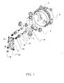
- Figure 1 is a schematic diagram of the present invention
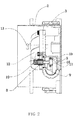
- Figure 2 is a sectional view of the present invention
- Figure 3 is the schematic diagram of an embedded body of the present invention.
- the present invention discloses a concealed shower valve (see Figure 1 ), including the circular shell 2 which is provided with four connection holes 1 around the periphery of the circular shell 2.
- Shell 2 is provided with an embedded body 4 with four water channels inside the embedded body 4.
- Four water channels include two water inlet channels and two water outlet channels. Water inlet channels can be divided into a cold water channel 19 and a hot water channel 22 (see Figure 3 ).
- the position of the water channel of the embedded body 4 corresponds to the position of the through hole on the shell.
- the lock nut 3 is arranged at a port of the water channel of the embedded body 4 which is fixed on the shell 2 through the lock nut.
- the four water channels of the embedded body 4 form a cross shape.
- the front side of the embedded body 4 is the plane 18.
- the hot water channel 22 and the cold water channel 19 are on the same line. Two water outlets are arranged on the same line.
- the plane 18 is provided with two big holes, the center of which deviates from the straight line of the hot water channel and the cold water channel.
- the screw thread is arranged along the edge of the inner side of the big hole.
- the embedded body 4 is provided with a cylindrical sink 17 that is on the same axis with the big hole.
- a buffer unit is arranged inside the sink 17.
- the hot water channel and the cold water channel are provided with a partition wall 15 with round holes.
- the bottom of the sink 17 is the same as the inlet of the cold water channel and the hot water channel.
- the sink 17 is provided with a round hole that communicates with the cold water channel and the hot water channel on the lateral side.
- the center of the round hole on partition wall 15 is on the same line with the center of the big hole.
- the plane 18 is provided with four through holes 20 which communicate with the water channels on the embedded body 4 respectively.
- the plane 18 is provided with 2 positioning holes 21.
- the shape of the cover board 12 matches with that of plane 18 on embedded body 4.
- the cover board 12 is provided with semi-round holes 11 away from the buffer unit on both sides.
- the cover board 12 is provided with screw holes around and fixed with the embedded body 4 through the screw.
- the cover board 12 is provided with two water stop holes 14 which have water stops 13 inside and reinforcing bars around.
- the cover board 12 is positioned based on the positioning hole.
- the buffer unit includes the coupling nut 9, the adjustment screw 10, the rubber seal ring 8, the booster spring 7, the central rod 6 and the rubber ring 5 (see Figure 2 ).
- the adjustment screw 10 is connected with the coupling nut 9 through the thread.
- the thread is sleeved with a rubber seal ring 8.
- the coupling nut 9 is provided with an outer thread and fixes the whole buffer unit on the big hole through the outer thread.
- the adjustment screw 10 provided with a compressed channel in the middle in which the booster spring 7 is arranged.
- the central rod 6 is in the shape of "T".
- the vertical part of the central rod 6 supports the booster spring 7 and compresses the spring 7 into the compressed channel.
- a sealing component 16 with a wedge barb is arranged at the center of the straight part of the central rod 6.
- the casing of the sealing component 16 is provided with a rubber ring 5. The barb limits the rubber ring 5.
- the sealing component 16 is inserted into the round hole on the partition wall 15.
- the rubber ring 5 seals the
- the control valve shall be installed when using the valve body. There is no valve body during packing.
- the cover board is used to cover the through hole of the plane of the valve body to keep impurities inside.
- the control valve is fixed on the plane of the valve body.
- the control hole on the control valve communicates with the through hole on the plane.
- the water outlet solution can be selected by the control valve. Cold water or hot water enters the bottom of the sink through the corresponding channel.
- the pressure of the water flow ejects the sealing component.
- the central rod compresses the booster spring to put the round hole in the middle of the partition wall through, thus communicating the water inlet channel and the outlet channel.
- the water pressure drops.
- the central rod drops automatically under the return force of the booster spring.
- the sealing component blocks the round hole in the middle of the partition wall again and closes the passage between the inlet channel and the outlet channel.
Landscapes
- Engineering & Computer Science (AREA)
- General Engineering & Computer Science (AREA)
- Mechanical Engineering (AREA)
- Nozzles (AREA)
- Mechanically-Actuated Valves (AREA)
Applications Claiming Priority (1)
| Application Number | Priority Date | Filing Date | Title |
|---|---|---|---|
| CN2010202571279U CN201715087U (zh) | 2010-07-14 | 2010-07-14 | 多功能暗装淋浴阀体 |
Publications (1)
| Publication Number | Publication Date |
|---|---|
| EP2407695A2 true EP2407695A2 (de) | 2012-01-18 |
Family
ID=43461084
Family Applications (1)
| Application Number | Title | Priority Date | Filing Date |
|---|---|---|---|
| EP20110171922 Withdrawn EP2407695A2 (de) | 2010-07-14 | 2011-06-29 | Multifunktionelles Unterputzduschventil |
Country Status (3)
| Country | Link |
|---|---|
| US (1) | US8820352B2 (de) |
| EP (1) | EP2407695A2 (de) |
| CN (1) | CN201715087U (de) |
Cited By (3)
| Publication number | Priority date | Publication date | Assignee | Title |
|---|---|---|---|---|
| CN104612217A (zh) * | 2014-11-26 | 2015-05-13 | 宁波敏宝卫浴五金水暖洁具有限公司 | 一种通用型阀体预埋盒结构 |
| EP3088614A4 (de) * | 2013-12-27 | 2017-08-02 | Xiamen Solex High-Tech Industries Co., Ltd. | Eingebaute voreingebettete anordnung |
| GB2598378A (en) * | 2020-08-28 | 2022-03-02 | Kohler Mira Ltd | A method of installing a control |
Families Citing this family (14)
| Publication number | Priority date | Publication date | Assignee | Title |
|---|---|---|---|---|
| CN102313069A (zh) * | 2011-06-27 | 2012-01-11 | 雅鼎卫浴股份有限公司 | 一种万能暗装淋浴控制机构 |
| CN103291993B (zh) * | 2012-02-29 | 2016-03-23 | 骊住株式会社 | 水龙头预埋阀体 |
| DE102012203393A1 (de) * | 2012-03-05 | 2013-09-05 | Hansgrohe Se | Höheneinstellbarer Putzdickenausgleich eines iBox Grundsets |
| US10072770B2 (en) | 2015-08-25 | 2018-09-11 | Kohler Co. | Valve body rough-in guide |
| US20170328042A1 (en) * | 2016-05-16 | 2017-11-16 | Dahata Inc. | Wall faucet |
| CN106051227A (zh) * | 2016-08-12 | 2016-10-26 | 佛山市诚牌卫浴有限公司 | 多功能淋浴控制阀 |
| CN110741192B (zh) | 2017-06-14 | 2022-03-22 | 株式会社电装 | 阀装置 |
| CN108413058A (zh) * | 2018-04-02 | 2018-08-17 | 曾宇杰 | 一种新型淋浴阀体 |
| CN108385769B (zh) * | 2018-05-03 | 2024-06-14 | 迈勒科(杭州)环保科技有限公司 | 一种用于二次供水的供水集成设备 |
| USD876585S1 (en) | 2018-05-09 | 2020-02-25 | As America, Inc. | Rough-in valve |
| CN108843823B (zh) * | 2018-08-21 | 2024-04-19 | 鹤山市斯帝罗兰卫浴洁具有限公司 | 一种分水阀预埋盒 |
| CN108843820B (zh) * | 2018-08-21 | 2024-02-23 | 鹤山市斯帝罗兰卫浴洁具有限公司 | 一种阀体预埋盒 |
| USD883447S1 (en) * | 2019-10-22 | 2020-05-05 | Guangdong SunRise Industrial Co., Ltd. | Shower valve |
| CN116497897B (zh) * | 2023-01-31 | 2026-03-17 | 湖南天力瑞家新材科技股份有限公司 | 一种全屋健康水系统 |
Citations (1)
| Publication number | Priority date | Publication date | Assignee | Title |
|---|---|---|---|---|
| CN201232801Y (zh) | 2008-04-30 | 2009-05-06 | 安晖 | 一种龙头主体预埋装置 |
Family Cites Families (12)
| Publication number | Priority date | Publication date | Assignee | Title |
|---|---|---|---|---|
| US4095610A (en) * | 1977-03-25 | 1978-06-20 | Powers Regulator Company | Pressure equalizing shower valve |
| US4243063A (en) * | 1979-09-14 | 1981-01-06 | American Standard Inc. | Mixing valve |
| US5884652A (en) * | 1997-05-27 | 1999-03-23 | Emhart Inc. | 2/3 handle pressure balancer system |
| US6601604B1 (en) * | 1998-05-08 | 2003-08-05 | Michael S. Cooper | Fire-control sprinkler system |
| US6050285A (en) * | 1998-10-14 | 2000-04-18 | Mark Controls Corporation | Pressure balancing valve |
| US6279604B1 (en) * | 2000-03-06 | 2001-08-28 | Moen Incorporated | Flow and temperature control valve handles |
| US6321777B1 (en) * | 2000-05-04 | 2001-11-27 | Faucet Wu | Wall-type shower faucet influent load control fixture |
| US6422520B1 (en) * | 2000-06-27 | 2002-07-23 | James F. Hand | Universal mounting bracket |
| US6718569B2 (en) * | 2002-04-12 | 2004-04-13 | Moen Incorporated | Tub and shower valve |
| US6761184B1 (en) * | 2003-11-25 | 2004-07-13 | Scott C. Jordan | Water flushing unit for a pressure balanced shower valve |
| US7458389B2 (en) * | 2004-04-19 | 2008-12-02 | Mark Doverspike | Bracket system for securing a single-lever-valves and associated water pipework to a support board |
| DE102004040084B4 (de) * | 2004-08-19 | 2009-08-06 | Hansa Metallwerke Ag | Sanitäre Unterputzarmatur |
-
2010
- 2010-07-14 CN CN2010202571279U patent/CN201715087U/zh not_active Expired - Fee Related
-
2011
- 2011-06-29 EP EP20110171922 patent/EP2407695A2/de not_active Withdrawn
- 2011-07-06 US US13/176,824 patent/US8820352B2/en not_active Expired - Fee Related
Patent Citations (1)
| Publication number | Priority date | Publication date | Assignee | Title |
|---|---|---|---|---|
| CN201232801Y (zh) | 2008-04-30 | 2009-05-06 | 安晖 | 一种龙头主体预埋装置 |
Cited By (4)
| Publication number | Priority date | Publication date | Assignee | Title |
|---|---|---|---|---|
| EP3088614A4 (de) * | 2013-12-27 | 2017-08-02 | Xiamen Solex High-Tech Industries Co., Ltd. | Eingebaute voreingebettete anordnung |
| CN104612217A (zh) * | 2014-11-26 | 2015-05-13 | 宁波敏宝卫浴五金水暖洁具有限公司 | 一种通用型阀体预埋盒结构 |
| GB2598378A (en) * | 2020-08-28 | 2022-03-02 | Kohler Mira Ltd | A method of installing a control |
| GB2598378B (en) * | 2020-08-28 | 2024-05-08 | Kohler Mira Ltd | A method of installing a control |
Also Published As
| Publication number | Publication date |
|---|---|
| US20120012210A1 (en) | 2012-01-19 |
| CN201715087U (zh) | 2011-01-19 |
| US8820352B2 (en) | 2014-09-02 |
Similar Documents
| Publication | Publication Date | Title |
|---|---|---|
| US8820352B2 (en) | Multi-functional concealed shower valve | |
| CN102498323B (zh) | 减压阀 | |
| MXPA04001970A (es) | Valvula de control de flujo. | |
| MX2007010263A (es) | Valvula vacuorreguladora de doble seguridad de drenaje automatico. | |
| US7891373B2 (en) | Flow control valve | |
| CN210859941U (zh) | 一种高压减压阀 | |
| US20150240463A1 (en) | Arrangement for handling a liquid medium | |
| CN111396609B (zh) | 带有减压组件的单向安全阀及应用其的热水器 | |
| CN210950073U (zh) | 一种压差旁通平衡阀 | |
| CN209876039U (zh) | 水龙头 | |
| RU2374542C2 (ru) | Клапан запорно-регулирующий | |
| JP6021194B2 (ja) | 2次側戻り水対策用逆止弁 | |
| JP3500589B2 (ja) | 水撃吸収機能付き水栓 | |
| RU2606002C1 (ru) | Поплавковый наполнительный клапан | |
| KR20150005294A (ko) | 개폐밸브 일체형 수도미터기용 감압밸브 | |
| CN206368985U (zh) | 马桶及其稳压阀 | |
| US20060185744A1 (en) | Fitting for liquids | |
| KR102669059B1 (ko) | 수직 일체형 수전 금구 | |
| CN101230930A (zh) | 管道防跑水装置 | |
| RU177144U1 (ru) | Предохранительный клапан | |
| CN109084058B (zh) | 一种自泄压式止回阀 | |
| CN101328985B (zh) | 组合式限流阀 | |
| KR20160001032U (ko) | 스핀들 작동 밸브와 과압 작동 밸브를 복합한 일체형 밸브 | |
| KR200354381Y1 (ko) | 흡배기밸브 | |
| CN107575584A (zh) | 一种限压角阀 |
Legal Events
| Date | Code | Title | Description |
|---|---|---|---|
| AK | Designated contracting states |
Kind code of ref document: A2 Designated state(s): AL AT BE BG CH CY CZ DE DK EE ES FI FR GB GR HR HU IE IS IT LI LT LU LV MC MK MT NL NO PL PT RO RS SE SI SK SM TR |
|
| AX | Request for extension of the european patent |
Extension state: BA ME |
|
| PUAI | Public reference made under article 153(3) epc to a published international application that has entered the european phase |
Free format text: ORIGINAL CODE: 0009012 |
|
| STAA | Information on the status of an ep patent application or granted ep patent |
Free format text: STATUS: THE APPLICATION IS DEEMED TO BE WITHDRAWN |
|
| 18D | Application deemed to be withdrawn |
Effective date: 20150106 |