EP2407257B1 - Plate curved surface forming device for square pressure head adjustable mold - Google Patents
Plate curved surface forming device for square pressure head adjustable mold Download PDFInfo
- Publication number
- EP2407257B1 EP2407257B1 EP10750374.0A EP10750374A EP2407257B1 EP 2407257 B1 EP2407257 B1 EP 2407257B1 EP 10750374 A EP10750374 A EP 10750374A EP 2407257 B1 EP2407257 B1 EP 2407257B1
- Authority
- EP
- European Patent Office
- Prior art keywords
- square
- adjustable
- rams
- square rams
- molds
- Prior art date
- Legal status (The legal status is an assumption and is not a legal conclusion. Google has not performed a legal analysis and makes no representation as to the accuracy of the status listed.)
- Not-in-force
Links
- 230000007246 mechanism Effects 0.000 claims abstract description 17
- 241001661918 Bartonia Species 0.000 claims description 10
- 238000004080 punching Methods 0.000 abstract description 16
- 230000015572 biosynthetic process Effects 0.000 description 23
- 238000000034 method Methods 0.000 description 17
- 238000003825 pressing Methods 0.000 description 8
- 238000005452 bending Methods 0.000 description 6
- 238000004519 manufacturing process Methods 0.000 description 5
- 238000010438 heat treatment Methods 0.000 description 3
- 230000007547 defect Effects 0.000 description 2
- 238000006073 displacement reaction Methods 0.000 description 2
- 230000008569 process Effects 0.000 description 2
- 230000009471 action Effects 0.000 description 1
- 238000010923 batch production Methods 0.000 description 1
- 229910003460 diamond Inorganic materials 0.000 description 1
- 239000010432 diamond Substances 0.000 description 1
- 238000005516 engineering process Methods 0.000 description 1
- 239000000463 material Substances 0.000 description 1
- 238000011089 mechanical engineering Methods 0.000 description 1
- 238000010137 moulding (plastic) Methods 0.000 description 1
- 230000002265 prevention Effects 0.000 description 1
- 230000009467 reduction Effects 0.000 description 1
- 230000001105 regulatory effect Effects 0.000 description 1
- 238000006467 substitution reaction Methods 0.000 description 1
Images


Classifications
-
- B—PERFORMING OPERATIONS; TRANSPORTING
- B21—MECHANICAL METAL-WORKING WITHOUT ESSENTIALLY REMOVING MATERIAL; PUNCHING METAL
- B21D—WORKING OR PROCESSING OF SHEET METAL OR METAL TUBES, RODS OR PROFILES WITHOUT ESSENTIALLY REMOVING MATERIAL; PUNCHING METAL
- B21D22/00—Shaping without cutting, by stamping, spinning, or deep-drawing
- B21D22/02—Stamping using rigid devices or tools
- B21D22/06—Stamping using rigid devices or tools having relatively-movable die parts
-
- B—PERFORMING OPERATIONS; TRANSPORTING
- B21—MECHANICAL METAL-WORKING WITHOUT ESSENTIALLY REMOVING MATERIAL; PUNCHING METAL
- B21D—WORKING OR PROCESSING OF SHEET METAL OR METAL TUBES, RODS OR PROFILES WITHOUT ESSENTIALLY REMOVING MATERIAL; PUNCHING METAL
- B21D37/00—Tools as parts of machines covered by this subclass
- B21D37/02—Die constructions enabling assembly of the die parts in different ways
Definitions
- the present utility model relates to a device for board member curved surface forming which is mainly used for the forming of the adjustable segmented mold such as outer board plate members of hull with 3D curved surface and processing by plastic punching, and belongs to mechanical engineering field.
- the traditional forming method mainly includes punching formation.
- punching formation is primarily used in large batch production.
- the processing of a part by this forming method generally requires several sets of integral type molds.
- the machined pieces formed by punching feature high precision and good quality, but there are still some problems such as high mold manufacturing cost and long production period.
- the existing representative technical literature includes:
- CN 2 460 239 Y which forms the base for the first part of claim 1, discloses a kind of dieless and multiple spot forming unit of plates, which is a kind of equipment used for plastic molding processing on plate.
- the equipment consists of upper and lower basic groups, adjusting mechanism and loading mechanism; the upper and lower basic group consists of a number of plunger chips, which is adjusted by the adjusting mechanism.
- One kind of adjusting mechanism consists of an adjustable pressure electromagnet and a flexible clamping chuck, used to adjust the plunger chip displacement; another kind of adjusting mechanism consists of a hydraulic cylinder and a selector valve, used to adjust both the plunger chip displacement and the plunger chip speed.
- CN 2 690 070 Y discloses a flexible forming die of trussing, consisting of the support frame, adjustment screw, plunger chip and telescopic device.
- the support frame has a guide sleeve fitted with the telescopic device, several adjustment screws are arranged in an array, each adjustment screw is provided in the guide sleeve, the adjustment screw is fixed to the support frame axially, the adjustment screw is connected with the telescopic device by screwing, the lower end of the telescopic unit has a replaceable plunger chip.
- the ram in Literature 1 has a spherical surface. When punching formation, it contacts the plate at "multiple points". The dents on the plates after punching are obvious and the compressed and deformed parts of the plate may generate harmful crumpling and deformation. To avoid crumpling and deformation, additional edge-pressing cylinder, edge-pressing ring or pad or similar measures shall be provided around the mold. Unfortunately, this is still impossible to properly solve the problems of big dents and crumpling and deformation.
- the ram in Literature 2 has a spherical surface capable of swinging along with the plate shape, but the contacting with the plate is also points-based and the contact area is larger.
- the ram in Literature 3 has a disk-shaped surface capable of swinging along with the plate shape. Although the contact area of the ram and plate is much larger than that above, many parts of the plate exposed between every two disk rams fail to be pressed, which may lead to the compressed and deformed parts of the plate generating harmful crumpling and deformation. In addition, due to the instability of the compressed parts of the plate, the pair of up & down-aligned rams are driven to swing, this still makes the plate generate harmful crumpling and deformation.
- the ram has either a disk-shaped surface or a spherical surface. It is a technical difficulty for multi-ram board and multi-point board formation processing to prevent the generation of crumpling and deformation and reduce dents during punching of boards.
- the present invention aims at providing curved surface forming device for adjustable segmented mold board with square rams, and providing a new adjustable segmented mold of square rams with new curved surface appearance for changing the line heating for the curved surface member of large-size boards of ship to cold bending, eliminating the harmful crumpling and deformation of the board curved surface member generated during punching, reducing dents, improving processing quality and for the processing of hull plate curved surface members so as to realize formation processing of hull plate members by means of cold punching.
- a curved surface forming device for an adjustable segmented mold board with square rams which essentially consists of an upper group and a lower group of square rams 1 capable of swinging, height adjustable molds 4 and a loading mechanism, wherein the upper group and the lower group of adjustable molds 4 are arranged in the loading mechanism and at least one group of adjustable molds 4 can move up and down under the drive of the loading mechanism.
- the adjustable molds 4 are provided with a group of square rams 1 in the quantity of M ⁇ N capable of swinging installed in the fixing frame 3, with the height of each square ram 1 adjustable, thus forming the upper or the lower adjustable molds 4; and a group of square rams 1 in the quantity of (M-1) ⁇ (N-1) capable of swinging installed on the supporting body 2 in the fixing frame 3, thus forming the upper or the lower adjustable molds 4; namely, when the mold of M ⁇ N square rams 1 is lower adjustable mold 4, the mold of (M-1) ⁇ (N-1) square rams 1 is upper adjustable mold 4; when the mold of M ⁇ N square rams 1 is upper adjustable mold 4, the mold of (M-1) ⁇ (N-1) square rams 1 is lower adjustable mold 4.
- the height of each square ram 1 in the upper and lower adjustable molds 4 is adjustable, and the square rams 1 of the upper and lower adjustable 4 are arranged in an interlaced manner in both transverse and longitudinal directions.
- the use of the upper and lower groups of adjustable molds 4 can rapidly form a designed curved surface 5 densely arranged with very small clearance between square rams and maximum press-fit area.
- the loading mechanism 6 can be used to drive the upper adjustable mold 4 downwards to apply pressure on the board 7, thus realizing the purpose of board formation, or the loading mechanism 6 is used to drive the upper and lower adjustable molds 4 respectively to apply pressure on the board 7.
- the adjustable molds 4 can preferably replace expensive integral type molds.
- the square rams 1 capable of swinging are composed of two parts: the square plate a and the sphere b.
- One side of the square plate a is pressure imposition surface and the other side is the sphere b; the pressure imposition surface is a plane or spherical surface; when the pressure imposition surface is a plane, the edge part can be provided with a taper or arc c.
- the sphere b is located on the supporting body 2 with concave spherical surface on the end in the fixing frame 3, and is flexibly coupled with the square rams 1 via the spring 8 so as to facilitate the swinging of the square rams 1.
- the other end of the supporting body 2 is connected with the motor (stepper motor) through a screw stem 9.
- the motor stepper motor
- the square rams 1, supporting body 2, spring 8, screw step 9 and the motor form a square ram unit.
- To control the motor by numerical control method can adjust the height of the ram unit, namely the height of the square rams 1.
- the upper and lower adjustable molds 4 are arranged in the following mode: the upper or lower adjustable molds 4 is composed of a group of (M - 1) ⁇ (N - 1) square rams 1 closely positioned in a rectangular shape, and the lower or upper adjustable mold 4 is compose of a group of M ⁇ N square rams 1 closely positioned in a rectangular shape, the projection of the center of the upper adjustable mold 4 and that of the lower adjustable mold 4 is coincident on a transverse plane, so the square rams 1 in the upper adjustable mold 4 and the lower adjustable mold 4 are symmetrically arranged in an interlaced manner in both transverse and longitudinal directions.
- the square rams 1 of the upper and lower adjustable molds 4 can be mutually supported without the possibility of inclined swinging of the square rams 1 due to the deformation of the boards. Meanwhile, the superposition of the clearance between the square rams 1 of the upper adjustable mold and the clearance between the square rams 1 of the lower adjustable mold can be avoided, thus effectively preventing the crumpling, deformation and dents. Finally, the board 7 can be enforced to perform plastic formation in the clearance between the upper and lower adjustable molds 4.
- the upper and lower adjustable molds 4 are provided with square rams 1 with plane pressure imposition surface, when the board is under punching, the square rams 1 contact the board on surface basis, thus greatly reducing the clearance between general rams.
- the rams 1 of the upper and lower adjustable molds 4 are arranged in an interlaced manner so that the square rams 1 can be mutually supported. Therefore, the square rams 1 may not generate inclined swinging due to the deformation of the materials. Meanwhile, the superposition of the clearance between the square rams 1 of the upper and lower adjustable molds 4 can be avoided.
- the use of the curved surface forming method of the boards for the adjustable segmented molds of square rams can rapidly form a curved surface densely arranged with very small clearance between square rams and maximum press-fit area.
- the smaller the size of the square rams 1, the narrower the clearance between the square rams 1, smoother curve shape and better quality can make the substitution with the expensive integral type mold in a better way.
- the square rams forming the adjustable segmented molds have a large area contacting the work piece to be processed, almost covering the whole board to be processed.
- the square rams in the upper and lower adjustable segmented molds are arranged in an interlaced manner in both transverse and longitudinal directions, can be mutually supported under pressure and may not generate inclined swinging due to the deformation of boards, so the boards are enforced to conduct plastic formation in the clearance defined by the upper and lower adjustable segmented molds, thus capable of effectively preventing the generation of crumpling defects, reducing the dent defects and dramatically improving the board formation quality.
- the adjustable molds 4 are designed. On the section of the adjustable molds 4, the transverse direction of the section of the square rams 1 is set to be parallel to the transverse direction of the section of the fixing frame 3; the longitudinal direction of the section of the square rams 1 is set to be parallel to the longitudinal direction of the section of the fixing frame 3.
- the adjustable molds 4 are designed. On the section of the adjustable molds 4, the angle included between the transverse direction of the section of the square rams 1 and the transverse direction of the section of the fixing frame 3 is set to be 45 ⁇ 6°; the angle included between the longitudinal direction of the section of the square rams 1 and the longitudinal direction of the section of the fixing frame 3 is set to be 45 ⁇ 6°.
- the curved surface forming device for adjustable segmented mold board with square rams are mainly used for the formation processing of large-scale 3D board such as the hull plate members in ship building.
- the square rams in the present invention are primarily used to construct the adjustable segmented molds densely arranged with very small clearance between rams and of near integral type to make any curved shape, thus addressing the technical difficulties of crumpling and deformation generated during board punching.
- FIG. 1 is the schematic view of the curved surface forming method by using the adjustable segmented molds of square rams.
- the adjustable molds 4 with M ⁇ N square rams 1 capable of swinging are installed in the fixing frame 3.
- the rams can be driven to move upwards or downwards by electric means or other methods, and can be adjusted on height by the numerical control method, forming the lower adjustable mold 4.
- the pressure imposition surface of the square rams 1 on the adjustable mold 4 is flat.
- the lower adjustable mold 4 can rapidly form a designed curved surface 5 densely arranged with very small clearance between square rams and maximum press-fit area.
- the adjustable molds 4 can preferably replace expensive integral type molds.
- the square size of the square rams 1 are slightly smaller than the square section size of the adjustable molds 4.
- the size of the square rams 1 shall be determined in accordance with the specifications of the normally used boards in real life processing.
- the section of the fixing frame 3 is provided with axis X and Y directions.
- the section of the square rams 1 is provided with axis X1 and Y1 directions.
- the sectional area for all the square rams 1 is set to be the same
- the axis X1 of the square rams 1 is set to be parallel to the axis X direction of the fixing frame 3
- the axis Y1 of the square rams 1 is set to be parallel to the axis Y direction of the fixing frame 3, so that the rams 1 in the adjustable molds 4 are arranged in a parallel and paracytic manner in both transverse direction and longitudinal direction on the section of the adjustable molds 4.
- the sectional area of all square rams 1 is set to be the same, the angle included between the axis X1 of the square rams 1 and the axis X of the fixing frame 3 is set to be 45°, and the angle included between the axis Y1 of the square rams 1 and the axis Y of the fixing frame 3 is set to be 45°, so that the rams in the adjustable molds 5 are arranged in a diamond manner in both transverse direction and longitudinal direction on the section of the adjustable molds 4.
- FIG. 2 is the schematic view of the ship plate curved surface forming method by using the adjustable segmented molds of square rams.
- the adjustable molds 4 with M ⁇ N square rams 1 capable of swinging are installed on the supporting body 2 in the fixing frame 3.
- the rams can be driven to move upwards or downwards by electric means or other methods, and can be adjusted on height by numerical control method, forming the lower adjustable mold 4.
- a group of (M - 1) ⁇ (N - 1) square rams 1 capable of swinging are installed on the supporting body 2 in the fixing frame 3.
- the rams can be driven to move upwards or downwards by electric means, and can be adjusted on height by numerical control method, forming the upper adjustable mold 4.
- the pressing machine 6 is used to drive the upper adjustable mold 4 to move downwards, and apply pressure on the board 7, thus to realize the purpose of board formation. Or use a group of (M - 1) ⁇ (N - 1) oil cylinders to drive various upper adjustable molds 4 respectively, forming the upper adjustable mold 4.
- To apply pressure on the board 7 placed between them can not only realize the 3D curved surface punching formation of the designed curved surface 5 to the board 7, but also achieve the purpose of preventing crumpling and deformation to be generated during board punching.
- the width shall meet the width requirement of ship plate 7, the length shall cover the length of the ship plate part. By means of feeding and formation in segments, the curved surface formation of relatively long ship plate can be realized.
- FIG. 3 is the schematic view of the composition of the ram unit in the adjustable molds.
- the ram unit is composed of the square rams 1, supporting body 2, screw stem 9 and motor 10.
- the motor 10 can drive the screw stem 9 to rotate and make the ram unit on the adjustable mold 4 move upwards or downwards under the action of the helical pair, thus to regulate the height of the square rams 1 on the end.
- a group of M ⁇ N square rams 1 on the adjustable molds 4 are regulated well according to the requirement of the designed curved surface 5, they can be use as the curved surface mold required by board formation.
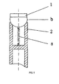
- FIG. 4 is the schematic view of the structural style of the square rams.
- the square rams 1 are composed of two parts: the square plate a and the sphere b.
- the pressure imposition surface of the square plate a is a plane or spherical surface with a large radius.
- the edge part of the pressure imposition surface can be provided with a taper or arc c so that the pressure imposition surface of the square rams 1 is not with a sharp angle and the dents on the plate can be avoided.
- the contact area between the square rams 1 and the board 7 is maximized, thus there are advantages of unstable pressure prevention on the board 7 and the reduction of dents.
- the adjustable molds 4 comprise a fixing frame 3 and the ram unit.
- M ⁇ N ram unit is arranged in the fixing frame 3.
- the ram unit is set to include square rams 1, supporting body 2, spring 8, screw stem 9 and motor 10.
- the square rams 1 are set to be composed of a square plate a and a sphere b.
- the upper end surface of the supporting body 2 is provided with a cavity.
- the square plate a of the square rams 1 is designed to be a plane.
- the sphere b of the square rams 1 is set to contact the upper end surface of the supporting body 2.
- the square rams 1 are set to connect the supporting body 2 via the spring 8.
- the lower end of the supporting body 2 is connected with the screw stem 9 which is designed to link the motor 10.
- the outer nut coupled with the screw stem is set to connect the fixing frame 3 in a fixed manner.
- FIG. 5 is the schematic view of the connection between the square rams and the adjustable molds.
- the square rams 1 must be fit for the bending of the board 7 and provided with sufficient swinging amplitude. Therefore, the sphere b part of the square rams 1 is located on the supporting body 2 with concave spherical surface on the end in the fixing frame 3.
- the spring 8 is used to flexibly and firmly connect the square rams 1 with the fixing frame 3 so that the square rams 1 can get the swinging requirement fit for the board curved surface formation.
- FIG. 6 is the schematic view of the arrangement of the upper and lower adjustable molds.
- the upper and lower adjustable molds are arranged in the following mode: an adjustable mold 4 is composed of a group of (M-1) ⁇ (N - 1) square rams 1 closely positioned in a rectangular shape, and an adjustable mold 4 is compose of a group of M ⁇ N square rams 1 closely positioned in a rectangular shape, the projection of the center of the upper adjustable mold 4 and that of the lower adjustable mold 4 is coincident on a transverse plane, so the square rams 1 in the upper adjustable mold 4 and the lower adjustable mold 4 are symmetrically arranged in an interlaced manner in both transverse and longitudinal directions.
- the square rams 1 When applying a pressure on the board 7, the square rams 1 can be mutually supported without the possibility of inclined swinging of the square rams 1 due to the deformation of the boards.
- Any square ram 1 on the upper adjustable mold 4 can be supported by the adjacent four square rams 1 on the upper adjustable mold 4.
- any square ram 1 on the lower adjustable mold 4 can be supported by the adjacent four square rams 1 on the upper adjustable mold 4.
- the square rams 1 may not have inclined swinging due to the instability of the board and can force the board 7 to conduct plastic formation in the clearance defined by the upper and lower molds, thus effectively preventing the crumpling of the board.
- the sectional area of all the square rams 1 is set to be the same.
- the upper adjustable mold 4 is set to be composed of (M- 1) ⁇ (N - 1) square rams 1 and the lower adjustable mold 4 is set to be composed of M ⁇ N square rams 1.
- the square rams 1 in the upper and lower adjustable molds 4 are set to be arranged in the same way.
- the central lines of the longitudinal section of the upper and lower molds 4 are set to be on the same vertical line, thus ensuring the manual supporting of the upper and lower square rams 1.
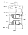
- FIG. 7 is the schematic view of the curved surface forming device for adjustable segmented mold board with square rams.
- the curved surface forming device for adjustable segmented mold board with square rams comprises: 1 - square rams, 2 - supporting body, 3- fixing frame, 4 - adjustable mold and 6 - pressing machine.
- the loading mechanism in this embodiment is pressing machine 6.
- the supporting body 2 with a group of square rams 1 is mounted in the fixing frame 3 to form the upper and the lower adjustable molds 4.
- the lower adjustable mold 4 is installed on the base 6(a) of the pressing machine 6.
- the upper adjustable mold 4 is installed on the movable cross beam 6(b) of the pressing machine 6.
- the movable cross beam 6(b) is connected with the pressure imposition oil cylinder 6(d) installed on the upper beam 6(c). Driven by the pressure imposition oil cylinder 6(d), the upper adjustable mold 4 can move upwards and downwards to punch the board to be processed together with the lower adjustable mold 4.
- the upper and the lower adjustable molds of the present invention is equipped with square rams 1 with the pressure imposition surface to be a plane, when punching the board, the square rams 1 contact the board on a surface basis, thus greatly reducing the clearance between the square rams 1.
- the square rams 1 of the upper and the lower adjustable molds are arranged in an interlaced manger, which leads to the impossibility of the superposition of the clearances between the square rams 1 of the upper and the lower adjustable molds, thus effectively preventing the crumpling, deformation and dents and improving processing quality.
Landscapes
- Engineering & Computer Science (AREA)
- Mechanical Engineering (AREA)
- Bending Of Plates, Rods, And Pipes (AREA)
- Shaping Metal By Deep-Drawing, Or The Like (AREA)
- Press Drives And Press Lines (AREA)
Abstract
Description
- The present utility model relates to a device for board member curved surface forming which is mainly used for the forming of the adjustable segmented mold such as outer board plate members of hull with 3D curved surface and processing by plastic punching, and belongs to mechanical engineering field.
- For the manufacturing of curved surface board parts, the traditional forming method mainly includes punching formation. However, punching formation is primarily used in large batch production. The processing of a part by this forming method generally requires several sets of integral type molds. The machined pieces formed by punching feature high precision and good quality, but there are still some problems such as high mold manufacturing cost and long production period.
- With the rapid growth of the economy in China, the shipbuilding industry is developing quickly. The members similar to the hull plates in shipbuilding feature very low batch size, complicated shape, large scale and small curvature. It is almost impossible to machine an integral type mold for processing due to expensive costs. Therefore, for hull plate members with simple curvature in the prior art, three-core roller or oil hydraulic press is generally used for processing; while for hull plate members with complicated curvature, based on a primary formation, manual line heating is adopted for longitudinal bending. As is known to all, the plate forming process of line heating has the disadvantages of poor production conditions, high labor strength, high requirement for technical skills of the workers and low production efficiency.
- Therefore, people began discussing the multi-ram and multi-point board formation.
- The existing representative technical literature includes:
- Literature 1: "Multi-point board formation device" for board punching (Patent Number: 02273508.9), etc.;
- Literature 2: Patent
DE4213490C1 and others used for airplane sheet skin technique; - Literature 3: the technical solution of "Japanese multi-ram plate bending machine" for shipbuilding (Ship-Building Technology, China Communications Press, December 1980, Page 141-149).
-
CN 2 460 239 Yclaim 1, discloses a kind of dieless and multiple spot forming unit of plates, which is a kind of equipment used for plastic molding processing on plate. The equipment consists of upper and lower basic groups, adjusting mechanism and loading mechanism; the upper and lower basic group consists of a number of plunger chips, which is adjusted by the adjusting mechanism. One kind of adjusting mechanism consists of an adjustable pressure electromagnet and a flexible clamping chuck, used to adjust the plunger chip displacement; another kind of adjusting mechanism consists of a hydraulic cylinder and a selector valve, used to adjust both the plunger chip displacement and the plunger chip speed. -
CN 2 690 070 Y - The ram in
Literature 1 has a spherical surface. When punching formation, it contacts the plate at "multiple points". The dents on the plates after punching are obvious and the compressed and deformed parts of the plate may generate harmful crumpling and deformation. To avoid crumpling and deformation, additional edge-pressing cylinder, edge-pressing ring or pad or similar measures shall be provided around the mold. Unfortunately, this is still impossible to properly solve the problems of big dents and crumpling and deformation. The ram inLiterature 2 has a spherical surface capable of swinging along with the plate shape, but the contacting with the plate is also points-based and the contact area is larger. To keep the smoothness of the plate, rubber pads or elastic pads shall be put under the plate to be processed, but the problems of big dents and crumpling and deformation still fail to be properly solved. The ram inLiterature 3 has a disk-shaped surface capable of swinging along with the plate shape. Although the contact area of the ram and plate is much larger than that above, many parts of the plate exposed between every two disk rams fail to be pressed, which may lead to the compressed and deformed parts of the plate generating harmful crumpling and deformation. In addition, due to the instability of the compressed parts of the plate, the pair of up & down-aligned rams are driven to swing, this still makes the plate generate harmful crumpling and deformation. It can be concluded from the literature above that the ram has either a disk-shaped surface or a spherical surface. It is a technical difficulty for multi-ram board and multi-point board formation processing to prevent the generation of crumpling and deformation and reduce dents during punching of boards. - The present invention aims at providing curved surface forming device for adjustable segmented mold board with square rams, and providing a new adjustable segmented mold of square rams with new curved surface appearance for changing the line heating for the curved surface member of large-size boards of ship to cold bending, eliminating the harmful crumpling and deformation of the board curved surface member generated during punching, reducing dents, improving processing quality and for the processing of hull plate curved surface members so as to realize formation processing of hull plate members by means of cold punching.
- The purpose of the present invention mentioned above is realized as follows (detailed as below in combination with the drawings):
- A curved surface forming device for an adjustable segmented mold board with square rams, which essentially consists of an upper group and a lower group of
square rams 1 capable of swinging, heightadjustable molds 4 and a loading mechanism, wherein the upper group and the lower group ofadjustable molds 4 are arranged in the loading mechanism and at least one group ofadjustable molds 4 can move up and down under the drive of the loading mechanism. - The
adjustable molds 4 are provided with a group ofsquare rams 1 in the quantity of M×N capable of swinging installed in thefixing frame 3, with the height of eachsquare ram 1 adjustable, thus forming the upper or the loweradjustable molds 4; and a group ofsquare rams 1 in the quantity of (M-1) × (N-1) capable of swinging installed on the supportingbody 2 in thefixing frame 3, thus forming the upper or the loweradjustable molds 4; namely, when the mold of M×Nsquare rams 1 is loweradjustable mold 4, the mold of (M-1) × (N-1)square rams 1 is upperadjustable mold 4; when the mold of M×Nsquare rams 1 is upperadjustable mold 4, the mold of (M-1) × (N-1)square rams 1 is loweradjustable mold 4. The height of eachsquare ram 1 in the upper and loweradjustable molds 4 is adjustable, and thesquare rams 1 of the upper and lower adjustable 4 are arranged in an interlaced manner in both transverse and longitudinal directions. - The use of the upper and lower groups of
adjustable molds 4 can rapidly form a designedcurved surface 5 densely arranged with very small clearance between square rams and maximum press-fit area. Theloading mechanism 6 can be used to drive the upperadjustable mold 4 downwards to apply pressure on the board 7, thus realizing the purpose of board formation, or theloading mechanism 6 is used to drive the upper and loweradjustable molds 4 respectively to apply pressure on the board 7. Theadjustable molds 4 can preferably replace expensive integral type molds. - The
square rams 1 capable of swinging are composed of two parts: the square plate a and the sphere b. One side of the square plate a is pressure imposition surface and the other side is the sphere b; the pressure imposition surface is a plane or spherical surface; when the pressure imposition surface is a plane, the edge part can be provided with a taper or arc c. The sphere b is located on the supportingbody 2 with concave spherical surface on the end in thefixing frame 3, and is flexibly coupled with thesquare rams 1 via thespring 8 so as to facilitate the swinging of thesquare rams 1. - The other end of the supporting
body 2 is connected with the motor (stepper motor) through ascrew stem 9. In this way, thesquare rams 1, supportingbody 2,spring 8, screwstep 9 and the motor form a square ram unit. To control the motor by numerical control method can adjust the height of the ram unit, namely the height of thesquare rams 1. - The upper and lower
adjustable molds 4 are arranged in the following mode: the upper or loweradjustable molds 4 is composed of a group of (M - 1) × (N - 1)square rams 1 closely positioned in a rectangular shape, and the lower or upperadjustable mold 4 is compose of a group of M×Nsquare rams 1 closely positioned in a rectangular shape, the projection of the center of the upperadjustable mold 4 and that of the loweradjustable mold 4 is coincident on a transverse plane, so thesquare rams 1 in the upperadjustable mold 4 and the loweradjustable mold 4 are symmetrically arranged in an interlaced manner in both transverse and longitudinal directions. When applying a pressure on the board 7, thesquare rams 1 of the upper and loweradjustable molds 4 can be mutually supported without the possibility of inclined swinging of thesquare rams 1 due to the deformation of the boards. Meanwhile, the superposition of the clearance between thesquare rams 1 of the upper adjustable mold and the clearance between thesquare rams 1 of the lower adjustable mold can be avoided, thus effectively preventing the crumpling, deformation and dents. Finally, the board 7 can be enforced to perform plastic formation in the clearance between the upper and loweradjustable molds 4. - Since the upper and lower
adjustable molds 4 are provided withsquare rams 1 with plane pressure imposition surface, when the board is under punching, thesquare rams 1 contact the board on surface basis, thus greatly reducing the clearance between general rams. Moreover, therams 1 of the upper and loweradjustable molds 4 are arranged in an interlaced manner so that thesquare rams 1 can be mutually supported. Therefore, thesquare rams 1 may not generate inclined swinging due to the deformation of the materials. Meanwhile, the superposition of the clearance between thesquare rams 1 of the upper and loweradjustable molds 4 can be avoided. - The use of the curved surface forming method of the boards for the adjustable segmented molds of square rams can rapidly form a curved surface densely arranged with very small clearance between square rams and maximum press-fit area. The smaller the size of the
square rams 1, the narrower the clearance between thesquare rams 1, smoother curve shape and better quality can make the substitution with the expensive integral type mold in a better way. Compared with other multiple rams or rams with multi-point board formation, the square rams forming the adjustable segmented molds have a large area contacting the work piece to be processed, almost covering the whole board to be processed. Meanwhile, the square rams in the upper and lower adjustable segmented molds are arranged in an interlaced manner in both transverse and longitudinal directions, can be mutually supported under pressure and may not generate inclined swinging due to the deformation of boards, so the boards are enforced to conduct plastic formation in the clearance defined by the upper and lower adjustable segmented molds, thus capable of effectively preventing the generation of crumpling defects, reducing the dent defects and dramatically improving the board formation quality. - In the present invention, the
adjustable molds 4 are designed. On the section of theadjustable molds 4, the transverse direction of the section of thesquare rams 1 is set to be parallel to the transverse direction of the section of thefixing frame 3; the longitudinal direction of the section of thesquare rams 1 is set to be parallel to the longitudinal direction of the section of thefixing frame 3. - In the present invention, the
adjustable molds 4 are designed. On the section of theadjustable molds 4, the angle included between the transverse direction of the section of thesquare rams 1 and the transverse direction of the section of the fixingframe 3 is set to be 45±6°; the angle included between the longitudinal direction of the section of thesquare rams 1 and the longitudinal direction of the section of the fixingframe 3 is set to be 45±6°. -
-
FIG. 1 is the schematic view of the curved surface forming method by using the adjustable segmented molds of square rams; -
FIG. 2 is the schematic view of the ship plate curved surface forming method by using the adjustable segmented molds of square rams; -
FIG. 3 is the schematic view of the composition of the ram unit in the adjustable molds; -
FIG. 4 is the schematic view of the structural style of the square rams; -
FIG. 5 is the schematic view of the connection between the square rams and the adjustable molds; -
FIG. 6 is the schematic view of the arrangement of the upper and lower adjustable molds; -
FIG. 7 is the schematic view of the board curved surface forming device by using the adjustable molds of square rams. - Where: 1 - square ram; 2 - supporting body; 3 - fixing frame; 4 - adjustable mold; 5 - designed curved surface; 6 - pressing machine; 7 - board; 8 - spring; 9-screw stem; 10 - drive motor.
- The specific contents and working process of the present invention are further detailed in combination with the embodiments shown in the drawings.
- The curved surface forming device for adjustable segmented mold board with square rams are mainly used for the formation processing of large-scale 3D board such as the hull plate members in ship building. Different from other board formation processing, the square rams in the present invention are primarily used to construct the adjustable segmented molds densely arranged with very small clearance between rams and of near integral type to make any curved shape, thus addressing the technical difficulties of crumpling and deformation generated during board punching.
-
FIG. 1 is the schematic view of the curved surface forming method by using the adjustable segmented molds of square rams. Theadjustable molds 4 with M×N square rams 1 capable of swinging are installed in the fixingframe 3. The rams can be driven to move upwards or downwards by electric means or other methods, and can be adjusted on height by the numerical control method, forming the loweradjustable mold 4. The pressure imposition surface of thesquare rams 1 on theadjustable mold 4 is flat. The loweradjustable mold 4 can rapidly form a designedcurved surface 5 densely arranged with very small clearance between square rams and maximum press-fit area. Theadjustable molds 4 can preferably replace expensive integral type molds. The square size of thesquare rams 1 are slightly smaller than the square section size of theadjustable molds 4. It is only required to meet the swinging requirement fit for the bending plate. The smaller the size of thesquare rams 1, the smoother the curved surface appearance and the better the quality. The size of thesquare rams 1 shall be determined in accordance with the specifications of the normally used boards in real life processing. - The section of the fixing
frame 3 is provided with axis X and Y directions. The section of thesquare rams 1 is provided with axis X1 and Y1 directions. In this embodiment, the sectional area for all thesquare rams 1 is set to be the same, the axis X1 of thesquare rams 1 is set to be parallel to the axis X direction of the fixingframe 3, and the axis Y1 of thesquare rams 1 is set to be parallel to the axis Y direction of the fixingframe 3, so that therams 1 in theadjustable molds 4 are arranged in a parallel and paracytic manner in both transverse direction and longitudinal direction on the section of theadjustable molds 4. In another embodiment of the present invention, the sectional area of allsquare rams 1 is set to be the same, the angle included between the axis X1 of thesquare rams 1 and the axis X of the fixingframe 3 is set to be 45°, and the angle included between the axis Y1 of thesquare rams 1 and the axis Y of the fixingframe 3 is set to be 45°, so that the rams in theadjustable molds 5 are arranged in a diamond manner in both transverse direction and longitudinal direction on the section of theadjustable molds 4. -
FIG. 2 is the schematic view of the ship plate curved surface forming method by using the adjustable segmented molds of square rams. Theadjustable molds 4 with M×N square rams 1 capable of swinging are installed on the supportingbody 2 in the fixingframe 3. The rams can be driven to move upwards or downwards by electric means or other methods, and can be adjusted on height by numerical control method, forming the loweradjustable mold 4. Similarly, a group of (M - 1)×(N - 1)square rams 1 capable of swinging are installed on the supportingbody 2 in the fixingframe 3. The rams can be driven to move upwards or downwards by electric means, and can be adjusted on height by numerical control method, forming the upperadjustable mold 4. Thepressing machine 6 is used to drive the upperadjustable mold 4 to move downwards, and apply pressure on the board 7, thus to realize the purpose of board formation. Or use a group of (M - 1)×(N - 1) oil cylinders to drive various upperadjustable molds 4 respectively, forming the upperadjustable mold 4. To apply pressure on the board 7 placed between them can not only realize the 3D curved surface punching formation of the designedcurved surface 5 to the board 7, but also achieve the purpose of preventing crumpling and deformation to be generated during board punching. As to theadjustable mold 4, the width shall meet the width requirement of ship plate 7, the length shall cover the length of the ship plate part. By means of feeding and formation in segments, the curved surface formation of relatively long ship plate can be realized. -
FIG. 3 is the schematic view of the composition of the ram unit in the adjustable molds. The ram unit is composed of thesquare rams 1, supportingbody 2, screw stem 9 andmotor 10. Themotor 10 can drive thescrew stem 9 to rotate and make the ram unit on theadjustable mold 4 move upwards or downwards under the action of the helical pair, thus to regulate the height of thesquare rams 1 on the end. When a group of M×N square rams 1 on theadjustable molds 4 are regulated well according to the requirement of the designedcurved surface 5, they can be use as the curved surface mold required by board formation. -
FIG. 4 is the schematic view of the structural style of the square rams. The square rams 1 are composed of two parts: the square plate a and the sphere b. The pressure imposition surface of the square plate a is a plane or spherical surface with a large radius. When the pressure imposition surface is a plane, the edge part of the pressure imposition surface can be provided with a taper or arc c so that the pressure imposition surface of thesquare rams 1 is not with a sharp angle and the dents on the plate can be avoided. Compared with other multi-ram board bending method or rams for the multi-point board forming device, the contact area between thesquare rams 1 and the board 7 is maximized, thus there are advantages of unstable pressure prevention on the board 7 and the reduction of dents. - In this embodiment, the
adjustable molds 4 comprise a fixingframe 3 and the ram unit. M×N ram unit is arranged in the fixingframe 3. The ram unit is set to includesquare rams 1, supportingbody 2,spring 8, screw stem 9 andmotor 10. The square rams 1 are set to be composed of a square plate a and a sphere b. The upper end surface of the supportingbody 2 is provided with a cavity. The square plate a of thesquare rams 1 is designed to be a plane. The sphere b of thesquare rams 1 is set to contact the upper end surface of the supportingbody 2. The square rams 1 are set to connect the supportingbody 2 via thespring 8. The lower end of the supportingbody 2 is connected with thescrew stem 9 which is designed to link themotor 10. The outer nut coupled with the screw stem is set to connect the fixingframe 3 in a fixed manner. -
FIG. 5 is the schematic view of the connection between the square rams and the adjustable molds. To realize the curved surface formation processing of the board 7, thesquare rams 1 must be fit for the bending of the board 7 and provided with sufficient swinging amplitude. Therefore, the sphere b part of thesquare rams 1 is located on the supportingbody 2 with concave spherical surface on the end in the fixingframe 3. Thespring 8 is used to flexibly and firmly connect thesquare rams 1 with the fixingframe 3 so that thesquare rams 1 can get the swinging requirement fit for the board curved surface formation. -
FIG. 6 is the schematic view of the arrangement of the upper and lower adjustable molds. The upper and lower adjustable molds are arranged in the following mode: anadjustable mold 4 is composed of a group of (M-1) × (N - 1)square rams 1 closely positioned in a rectangular shape, and anadjustable mold 4 is compose of a group of M×N square rams 1 closely positioned in a rectangular shape, the projection of the center of the upperadjustable mold 4 and that of the loweradjustable mold 4 is coincident on a transverse plane, so thesquare rams 1 in the upperadjustable mold 4 and the loweradjustable mold 4 are symmetrically arranged in an interlaced manner in both transverse and longitudinal directions. When applying a pressure on the board 7, thesquare rams 1 can be mutually supported without the possibility of inclined swinging of thesquare rams 1 due to the deformation of the boards. Anysquare ram 1 on the upperadjustable mold 4 can be supported by the adjacent foursquare rams 1 on the upperadjustable mold 4. On the contrary, anysquare ram 1 on the loweradjustable mold 4 can be supported by the adjacent foursquare rams 1 on the upperadjustable mold 4. The square rams 1 may not have inclined swinging due to the instability of the board and can force the board 7 to conduct plastic formation in the clearance defined by the upper and lower molds, thus effectively preventing the crumpling of the board. - In this embodiment, the sectional area of all the
square rams 1 is set to be the same. The upperadjustable mold 4 is set to be composed of (M- 1)×(N - 1)square rams 1 and the loweradjustable mold 4 is set to be composed of M×N square rams 1. The square rams 1 in the upper and loweradjustable molds 4 are set to be arranged in the same way. The central lines of the longitudinal section of the upper andlower molds 4 are set to be on the same vertical line, thus ensuring the manual supporting of the upper and lower square rams 1. -
FIG. 7 is the schematic view of the curved surface forming device for adjustable segmented mold board with square rams. The curved surface forming device for adjustable segmented mold board with square rams comprises: 1 - square rams, 2 - supporting body, 3- fixing frame, 4 - adjustable mold and 6 - pressing machine. The loading mechanism in this embodiment is pressingmachine 6. The supportingbody 2 with a group ofsquare rams 1 is mounted in the fixingframe 3 to form the upper and the loweradjustable molds 4. The loweradjustable mold 4 is installed on the base 6(a) of thepressing machine 6. The upperadjustable mold 4 is installed on the movable cross beam 6(b) of thepressing machine 6. The movable cross beam 6(b) is connected with the pressure imposition oil cylinder 6(d) installed on the upper beam 6(c). Driven by the pressure imposition oil cylinder 6(d), the upperadjustable mold 4 can move upwards and downwards to punch the board to be processed together with the loweradjustable mold 4. - Based on the description above, the upper and the lower adjustable molds of the present invention is equipped with
square rams 1 with the pressure imposition surface to be a plane, when punching the board, thesquare rams 1 contact the board on a surface basis, thus greatly reducing the clearance between the square rams 1. The square rams 1 of the upper and the lower adjustable molds are arranged in an interlaced manger, which leads to the impossibility of the superposition of the clearances between thesquare rams 1 of the upper and the lower adjustable molds, thus effectively preventing the crumpling, deformation and dents and improving processing quality.
Claims (5)
- A curved surface forming device for an adjustable segmented mold board with square rams, essentially consisting of an upper group and a lower group of square rams (1) capable of swinging, height adjustable molds (4) and a loading mechanism, wherein the upper group and the lower group of adjustable molds (4) are arranged in the loading mechanism and at least one group of the adjustable molds (4) can move up and down under the drive of the loading mechanism; the height of each square ram (1) in the upper and the lower adjustable molds (4) can be adjustable, the square rams (1) are composed of two parts: the square plate (a) and the sphere (b); one side of the square plate (a) is pressure imposition surface and the other side is the sphere (b); the pressure imposition surface of the square plate (a) is a plane or spherical surface; characterized in that the adjustable molds (4) are provided with a group of square rams (1) in the quantity of M×N capable of swinging installed on the supporting body (2) in the fixing frame (3), forming the lower or the upper adjustable molds (4); and a group of square rams (1) in the quantity of (M-1) × (N-1) capable of swinging installed on the supporting body (2) in the fixing frame (3), thus forming the upper or the lower adjustable molds (4); the square rams (1) of the upper and the lower adjustable molds (4) are arranged in an interlaced manner in both transverse and longitudinal directions; the pressure imposition surface of the square plate (a) is a plane, the edge part of the pressure imposition surface is provided with a taper or arc (c); the sphere (b) is located on the inner end concave spherical surface of the supporting body (2), and is flexibly coupled with the square rams (1) via the spring (8).
- The curved surface forming device for an adjustable segmented mold board with square rams as claimed in Claim 1, characterized in that the sectional area of all the square rams (1) is set to be the same, the upper adjustable mold (4) is set to be composed of (M-1)×(N-1) square rams (1) and the lower adjustable mold (4) is set to be composed of M×N square rams (1), the square rams (1) in the upper and lower adjustable molds (4) are set to be arranged in the same way, the central lines of the longitudinal section of the upper and lower molds (4) are set to be on the same vertical line.
- An adjustable mold, comprising a fixing frame (3) and the ram unit, wherein a M×N ram unit is arranged in the fixing frame (3); the ram unit is set to include square rams (1), supporting body (2), spring (8), screw stem (9) and motor (10); the square rams (1) are connected to the supporting body (2) via the spring (8); the lower end of the supporting body (2) is connected with the screw stem (9) which is designed to link the motor (10); the outer nut coupled with the screw stem (9), the screw stem (9) is connected to the fixing frame (3) in a fixed manner, characterized in that the square rams (1) are set to be composed of a square plate (a) and a sphere (b); the upper end surface of the supporting body (2) is provided with a cavity; the square plate (a) of the square rams (1) is designed to be a plane; the edge part of the pressure imposition surface of the square plate (a) is provided with a taper or arc (c); the sphere (b) of the square rams (1) is in contact with the upper end surface of the supporting body (2).
- The adjustable mold as claimed in Claim 3, characterized in that, on the section of the adjustable molds (4), the transverse direction of the section of the square rams (1) is set to be parallel to the transverse direction of the section of the fixing frame (3); the longitudinal direction of the section of the square rams (1) is set to be parallel to the longitudinal direction of the section of the fixing frame (3).
- The adjustable mold as claimed in Claim 3, characterized in that, on the section of the adjustable molds (4), the angle included between the transverse direction of the section of the square rams (1) and the transverse direction of the section of the fixing frame (3) is set to be 45±6°; the angle included between the longitudinal direction of the section of the square rams (1) and the longitudinal direction of the section of the fixing frame (3) is set to be 45±6°.
Applications Claiming Priority (2)
| Application Number | Priority Date | Filing Date | Title |
|---|---|---|---|
| CN2009100147946A CN101549377B (en) | 2009-03-12 | 2009-03-12 | Curved surface forming device for adjustable segmented mold board of square rams |
| PCT/CN2010/071008 WO2010102578A1 (en) | 2009-03-12 | 2010-03-12 | Plate curved surface forming device for square pressure head adjustable mold |
Publications (3)
| Publication Number | Publication Date |
|---|---|
| EP2407257A1 EP2407257A1 (en) | 2012-01-18 |
| EP2407257A4 EP2407257A4 (en) | 2012-08-08 |
| EP2407257B1 true EP2407257B1 (en) | 2013-11-20 |
Family
ID=41153998
Family Applications (1)
| Application Number | Title | Priority Date | Filing Date |
|---|---|---|---|
| EP10750374.0A Not-in-force EP2407257B1 (en) | 2009-03-12 | 2010-03-12 | Plate curved surface forming device for square pressure head adjustable mold |
Country Status (7)
| Country | Link |
|---|---|
| US (1) | US8939754B2 (en) |
| EP (1) | EP2407257B1 (en) |
| JP (1) | JP5464616B2 (en) |
| KR (1) | KR101300761B1 (en) |
| CN (1) | CN101549377B (en) |
| AU (1) | AU2010223744B2 (en) |
| WO (1) | WO2010102578A1 (en) |
Cited By (1)
| Publication number | Priority date | Publication date | Assignee | Title |
|---|---|---|---|---|
| DE102016103389A1 (en) | 2016-02-25 | 2017-08-31 | Gabriel Pausch | Shaping device for producing curved surfaces |
Families Citing this family (39)
| Publication number | Priority date | Publication date | Assignee | Title |
|---|---|---|---|---|
| CN101549377B (en) | 2009-03-12 | 2011-01-12 | 泰安市硕力液压设备厂 | Curved surface forming device for adjustable segmented mold board of square rams |
| CN102485491B (en) * | 2010-12-03 | 2014-10-15 | 六福集团有限公司 | Upper and lower cover type printing seat |
| RU2466814C1 (en) * | 2011-04-28 | 2012-11-20 | Федеральное государственное бюджетное образовательное учреждение высшего профессионального образования "Рыбинский государственный авиационный технический университет имени П.А. Соловьева" | Method of making discrete die bed |
| NO20111156A1 (en) * | 2011-08-25 | 2013-01-02 | Trampooline Ltd | Device for jumping and water activities |
| CN102699214B (en) * | 2012-05-21 | 2014-05-28 | 西安交通大学 | Shape adjusting device of reconfigurable mould |
| CN102974685A (en) * | 2012-12-20 | 2013-03-20 | 哈尔滨工业大学(威海) | Hemispherical pressure head assembly for multi-point forming of sheet |
| CN103240362A (en) * | 2013-05-06 | 2013-08-14 | 大连船舶重工集团装备制造有限公司 | Cold-forming device for ship body curved-surface planking |
| CN103447359A (en) * | 2013-09-06 | 2013-12-18 | 山东硕力机械制造有限公司 | Pressing head for cold bending machine for forming three-dimensional panel |
| CN103551463A (en) * | 2013-11-05 | 2014-02-05 | 镇江市高等专科学校 | Adjustable forming die for blades of centrifugal fans |
| US9550227B2 (en) | 2013-12-11 | 2017-01-24 | Toyota Boshoku Kabushiki Kaisha | Press molding machine |
| CN104139129A (en) * | 2014-07-07 | 2014-11-12 | 吉林大学 | Multi-point forming technology-applied forming method for curved-surface ship board |
| JP6528701B2 (en) * | 2015-06-08 | 2019-06-12 | 株式会社デンソー | Production method |
| CN104998947B (en) * | 2015-07-31 | 2017-04-12 | 燕山大学 | Thick plate space curved face forming method based on multi-point die |
| CN105665631B (en) | 2016-01-26 | 2018-01-05 | 机械科学研究总院先进制造技术研究中心 | A kind of flexible extruding near-net-shape optimization method of sand mold digitlization based on searching algorithm |
| CN105903796B (en) * | 2016-04-20 | 2019-02-12 | 深圳市华星光电技术有限公司 | Curved display backplane forming equipment and forming method |
| CN106345860B (en) * | 2016-08-25 | 2018-11-02 | 江南造船(集团)有限责任公司 | Active processing unit (plant) and bent plate forming method is adjusted for the processing of ship bent plate |
| US10603835B2 (en) * | 2017-02-08 | 2020-03-31 | Hall Labs Llc | Pin die thermoforming apparatus |
| CN107282774A (en) * | 2017-07-07 | 2017-10-24 | 宁波港瑞汽车零部件有限公司 | A kind of bending machine mould |
| CN107597940A (en) * | 2017-08-17 | 2018-01-19 | 吉林省柔创机电科技有限公司 | Sheet material multiple spot subregion manufacturing process and subregion pressing type multi-point formation apparatus |
| CN107335718B (en) * | 2017-08-23 | 2018-10-26 | 西北工业大学 | A kind of autoclave integral panel creep age forming flexible frock |
| FR3072361B1 (en) * | 2017-10-17 | 2019-11-22 | Airbus Operations | LANDING TRAIN CASE ROOF COMPRISING AT LEAST ONE PORTIC INSTALLED AGAINST A LOWER SURFACE OF ITS WALL |
| CN108163137A (en) * | 2017-12-23 | 2018-06-15 | 宁波高新区若水智创科技有限公司 | A kind of mobile adjustable propeller corrector |
| US11253898B2 (en) * | 2018-10-18 | 2022-02-22 | The Boeing Company | Hot-forming presses and methods of hot-forming workpieces |
| US11072011B2 (en) | 2018-10-18 | 2021-07-27 | The Boeing Company | Hot boxes for hot-forming presses |
| CN109808104B (en) * | 2019-04-04 | 2020-10-16 | 吉林大学 | Gap eliminating mechanism for multi-point die forming SMC composite material workpiece |
| CN110064685B (en) * | 2019-04-09 | 2024-04-30 | 山东中硕机械装备制造有限公司 | Support body of reconfigurable plate bending machine with buffering function |
| US11001016B2 (en) * | 2019-04-22 | 2021-05-11 | Massachusetts Institute Of Technology | Methods and apparatus for reconfigurable heated mold |
| CN111421060B (en) * | 2020-03-16 | 2022-02-15 | 重庆庆铃模具有限公司 | Punching compound die and punching machine |
| CN112775288B (en) * | 2020-12-11 | 2022-10-18 | 渤海造船厂集团有限公司 | Flexible forming method for ship outer plate with complex curved surface |
| CN112917789B (en) * | 2021-01-27 | 2022-08-30 | 业成科技(成都)有限公司 | Hot press molding process and hot press device thereof |
| CN112936476B (en) * | 2021-01-27 | 2022-12-13 | 江苏怡通控制系统有限公司 | Multi-angle bending device |
| CN113290098B (en) * | 2021-04-15 | 2023-01-06 | 佛山市南海圣特亮装饰材料有限公司 | Protection and detection device during press forming of stainless steel corrugated plate |
| CN113386337B (en) * | 2021-06-10 | 2022-08-09 | 四川航天长征装备制造有限公司 | Multistage adjustable indentation die |
| CN114038336B (en) * | 2021-12-06 | 2023-02-07 | 武汉华星光电半导体显示技术有限公司 | Profiling device, manufacturing method of display panel and display panel |
| CN114951367A (en) * | 2022-06-29 | 2022-08-30 | 中航西安飞机工业集团股份有限公司 | Mould for forming tool type plate of composite material forming of INVAR steel matrix |
| CN115382967A (en) * | 2022-08-02 | 2022-11-25 | 山东中硕机械装备制造有限公司 | Curved surface forming device and method for metal sheet and application thereof |
| CN115815421A (en) * | 2022-12-06 | 2023-03-21 | 吉林大学 | A rapid stamping forming device for complex curved surface parts |
| CN116893097B (en) * | 2023-09-11 | 2023-12-05 | 吉林亚泰建筑工程有限公司 | Concrete test block crack resistance continuous detection device capable of automatically discharging and cleaning |
| KR102907178B1 (en) * | 2023-11-24 | 2026-01-02 | 이재신 | System for manufacturing skin of aircraft |
Family Cites Families (23)
| Publication number | Priority date | Publication date | Assignee | Title |
|---|---|---|---|---|
| DE423490C (en) | 1926-01-05 | Hans Roecke | Fluid return brake with air reclaimer for guns | |
| US1312268A (en) * | 1919-08-05 | Machine fob bebtdhstg leaf-springs | ||
| US1295542A (en) * | 1913-08-04 | 1919-02-25 | Standard Parts Co | Plate-bending machine. |
| JPS48103066A (en) * | 1972-04-13 | 1973-12-24 | ||
| JPS54730B2 (en) | 1973-11-07 | 1979-01-16 | ||
| JPS5162471A (en) * | 1974-11-28 | 1976-05-31 | Mitsubishi Heavy Ind Ltd | SANJOPURE SUSOCHI |
| US4212188A (en) * | 1979-01-18 | 1980-07-15 | The Boeing Company | Apparatus for forming sheet metal |
| FR2449534A1 (en) * | 1979-02-21 | 1980-09-19 | Saint Gobain | DEVICE FOR ASSEMBLING GLASS SHEETS AND / OR PLASTIC MATERIALS |
| JP3212121B2 (en) * | 1991-04-08 | 2001-09-25 | 株式会社日立製作所 | Multipoint press for forming multi-curved surfaces and forming method thereof |
| DE4213490C1 (en) * | 1992-04-24 | 1993-09-30 | Deutsche Aerospace Airbus | Composite shaping body for stretch-forming machine - has supporting heads with similarly-curving surfaces tilting in all directions on jacks for elastic cover accommodating metal sheet |
| US5546784A (en) * | 1994-12-05 | 1996-08-20 | Grumman Aerospace Corporation | Adjustable form die |
| US6354561B1 (en) * | 1996-07-11 | 2002-03-12 | Otmar Fahrion | Adjustable casting mould, and device for adjusting the mould surface thereof |
| CN2460239Y (en) * | 2000-08-10 | 2001-11-21 | 吉林工业大学 | Non-mould multi-point forming device for plate |
| JP2002301526A (en) * | 2001-04-02 | 2002-10-15 | Mitsubishi Heavy Ind Ltd | Pin-connected construction of general purpose forming die |
| CN2548792Y (en) * | 2002-05-23 | 2003-05-07 | 吉林大学 | Multiple spot shaper of plates |
| CN2670024Y (en) * | 2003-12-24 | 2005-01-12 | 湖南大学 | A Discrete Surface Die Device for Sheet Metal Thermoforming |
| CN2690070Y (en) * | 2004-04-23 | 2005-04-06 | 宋爱平 | Rod serics flexible forming mold |
| CN101036926A (en) * | 2007-04-30 | 2007-09-19 | 武汉理工大学 | Huoluo hemisphere type pressure head base body of multi-pressure-head sheet forming device |
| JP5076937B2 (en) | 2008-02-06 | 2012-11-21 | セイコーエプソン株式会社 | Sheet medium feeding apparatus and sheet medium processing apparatus |
| CN101342558B (en) * | 2008-08-18 | 2011-11-23 | 吉林大学 | Sectional type multi-point shape adjusting device for three-dimensional curve generation of sheet |
| CN101444810B (en) * | 2008-12-30 | 2011-04-06 | 吉林大学 | Staggering-arraying type multi-point forming device of elementary units |
| CN101549377B (en) * | 2009-03-12 | 2011-01-12 | 泰安市硕力液压设备厂 | Curved surface forming device for adjustable segmented mold board of square rams |
| CN201361652Y (en) * | 2009-03-12 | 2009-12-16 | 泰安市硕力液压设备厂 | Adjustable curved surface forming device provides with square pressure heads and used for boards of segmental mold |
-
2009
- 2009-03-12 CN CN2009100147946A patent/CN101549377B/en not_active Expired - Fee Related
-
2010
- 2010-03-12 JP JP2011553268A patent/JP5464616B2/en not_active Expired - Fee Related
- 2010-03-12 KR KR1020117017635A patent/KR101300761B1/en not_active Expired - Fee Related
- 2010-03-12 US US13/138,466 patent/US8939754B2/en active Active
- 2010-03-12 WO PCT/CN2010/071008 patent/WO2010102578A1/en not_active Ceased
- 2010-03-12 AU AU2010223744A patent/AU2010223744B2/en not_active Ceased
- 2010-03-12 EP EP10750374.0A patent/EP2407257B1/en not_active Not-in-force
Cited By (1)
| Publication number | Priority date | Publication date | Assignee | Title |
|---|---|---|---|---|
| DE102016103389A1 (en) | 2016-02-25 | 2017-08-31 | Gabriel Pausch | Shaping device for producing curved surfaces |
Also Published As
| Publication number | Publication date |
|---|---|
| AU2010223744A1 (en) | 2011-09-29 |
| WO2010102578A1 (en) | 2010-09-16 |
| KR20110111431A (en) | 2011-10-11 |
| US20110300254A1 (en) | 2011-12-08 |
| CN101549377B (en) | 2011-01-12 |
| US8939754B2 (en) | 2015-01-27 |
| EP2407257A4 (en) | 2012-08-08 |
| EP2407257A1 (en) | 2012-01-18 |
| JP5464616B2 (en) | 2014-04-09 |
| CN101549377A (en) | 2009-10-07 |
| JP2012519594A (en) | 2012-08-30 |
| KR101300761B1 (en) | 2013-09-10 |
| AU2010223744B2 (en) | 2013-11-07 |
Similar Documents
| Publication | Publication Date | Title |
|---|---|---|
| AU2010223744B2 (en) | Plate curved surface forming device for square pressure head adjustable mold | |
| CN102101363B (en) | Multi-point forming device for plate | |
| CN101670392A (en) | Unmatched pressing multipoint board forming device | |
| CN107160207B (en) | Swinging seat drilling tool | |
| CN220783610U (en) | Multi-acupoint clamp with long frame | |
| CN202052854U (en) | Adjustable U-shaped bending die for precise curved surface | |
| CN2548792Y (en) | Multiple spot shaper of plates | |
| CN201862695U (en) | Longitudinal beam bending mould structure | |
| CN201361652Y (en) | Adjustable curved surface forming device provides with square pressure heads and used for boards of segmental mold | |
| CN101829722A (en) | Device for dieless progressive molding of metal plate | |
| CN201020496Y (en) | Machinery compensation working bench | |
| CN2741690Y (en) | Pulling mold | |
| CN201519712U (en) | Non-pressure multi-point sheet metal forming device | |
| CN208772272U (en) | A kind of tension and compression composite board stretch former | |
| CN118287573A (en) | Device and method for forming three-dimensional curved surface of plate | |
| CN113926893B (en) | Device and method for stamping and forming hyperbolic outer plate with small curvature radius | |
| CN210358890U (en) | Elastic steel band clamp anti-flanging die | |
| CN115156394A (en) | Aluminum alloy variable-curvature multi-point forming equipment for aerospace plane | |
| CN211437577U (en) | Stamping die for large negative angle bending forming | |
| CN203842983U (en) | Multifunctional jacking bending machine | |
| CN208467018U (en) | A kind of blanking die mechanism | |
| CN201511094U (en) | Valve forging total length fixing mechanism | |
| CN107537962A (en) | Hydraulic automatic locking forging dies device | |
| CN114570769A (en) | Three-dimensional curved surface rolling mill | |
| CN223011573U (en) | Panel bender is used in panel processing |
Legal Events
| Date | Code | Title | Description |
|---|---|---|---|
| PUAI | Public reference made under article 153(3) epc to a published international application that has entered the european phase |
Free format text: ORIGINAL CODE: 0009012 |
|
| 17P | Request for examination filed |
Effective date: 20110704 |
|
| AK | Designated contracting states |
Kind code of ref document: A1 Designated state(s): AT BE BG CH CY CZ DE DK EE ES FI FR GB GR HR HU IE IS IT LI LT LU LV MC MK MT NL NO PL PT RO SE SI SK SM TR |
|
| DAX | Request for extension of the european patent (deleted) | ||
| A4 | Supplementary search report drawn up and despatched |
Effective date: 20120710 |
|
| RIC1 | Information provided on ipc code assigned before grant |
Ipc: B21D 22/06 20060101AFI20120704BHEP Ipc: B21D 37/02 20060101ALI20120704BHEP |
|
| 17Q | First examination report despatched |
Effective date: 20120906 |
|
| GRAP | Despatch of communication of intention to grant a patent |
Free format text: ORIGINAL CODE: EPIDOSNIGR1 |
|
| INTG | Intention to grant announced |
Effective date: 20130718 |
|
| GRAS | Grant fee paid |
Free format text: ORIGINAL CODE: EPIDOSNIGR3 |
|
| GRAA | (expected) grant |
Free format text: ORIGINAL CODE: 0009210 |
|
| AK | Designated contracting states |
Kind code of ref document: B1 Designated state(s): AT BE BG CH CY CZ DE DK EE ES FI FR GB GR HR HU IE IS IT LI LT LU LV MC MK MT NL NO PL PT RO SE SI SK SM TR |
|
| REG | Reference to a national code |
Ref country code: GB Ref legal event code: FG4D |
|
| REG | Reference to a national code |
Ref country code: CH Ref legal event code: EP |
|
| REG | Reference to a national code |
Ref country code: AT Ref legal event code: REF Ref document number: 641265 Country of ref document: AT Kind code of ref document: T Effective date: 20131215 |
|
| REG | Reference to a national code |
Ref country code: IE Ref legal event code: FG4D |
|
| REG | Reference to a national code |
Ref country code: DE Ref legal event code: R096 Ref document number: 602010011928 Country of ref document: DE Effective date: 20140116 |
|
| RAP2 | Party data changed (patent owner data changed or rights of a patent transferred) |
Owner name: SHANDONG SURELY MACHINERY COMPANY LIMITED |
|
| REG | Reference to a national code |
Ref country code: NL Ref legal event code: T3 |
|
| REG | Reference to a national code |
Ref country code: AT Ref legal event code: MK05 Ref document number: 641265 Country of ref document: AT Kind code of ref document: T Effective date: 20131120 |
|
| REG | Reference to a national code |
Ref country code: LT Ref legal event code: MG4D |
|
| PG25 | Lapsed in a contracting state [announced via postgrant information from national office to epo] |
Ref country code: NO Free format text: LAPSE BECAUSE OF FAILURE TO SUBMIT A TRANSLATION OF THE DESCRIPTION OR TO PAY THE FEE WITHIN THE PRESCRIBED TIME-LIMIT Effective date: 20140220 Ref country code: LT Free format text: LAPSE BECAUSE OF FAILURE TO SUBMIT A TRANSLATION OF THE DESCRIPTION OR TO PAY THE FEE WITHIN THE PRESCRIBED TIME-LIMIT Effective date: 20131120 Ref country code: SE Free format text: LAPSE BECAUSE OF FAILURE TO SUBMIT A TRANSLATION OF THE DESCRIPTION OR TO PAY THE FEE WITHIN THE PRESCRIBED TIME-LIMIT Effective date: 20131120 Ref country code: HR Free format text: LAPSE BECAUSE OF FAILURE TO SUBMIT A TRANSLATION OF THE DESCRIPTION OR TO PAY THE FEE WITHIN THE PRESCRIBED TIME-LIMIT Effective date: 20131120 Ref country code: IS Free format text: LAPSE BECAUSE OF FAILURE TO SUBMIT A TRANSLATION OF THE DESCRIPTION OR TO PAY THE FEE WITHIN THE PRESCRIBED TIME-LIMIT Effective date: 20140320 Ref country code: FI Free format text: LAPSE BECAUSE OF FAILURE TO SUBMIT A TRANSLATION OF THE DESCRIPTION OR TO PAY THE FEE WITHIN THE PRESCRIBED TIME-LIMIT Effective date: 20131120 |
|
| PG25 | Lapsed in a contracting state [announced via postgrant information from national office to epo] |
Ref country code: AT Free format text: LAPSE BECAUSE OF FAILURE TO SUBMIT A TRANSLATION OF THE DESCRIPTION OR TO PAY THE FEE WITHIN THE PRESCRIBED TIME-LIMIT Effective date: 20131120 Ref country code: ES Free format text: LAPSE BECAUSE OF FAILURE TO SUBMIT A TRANSLATION OF THE DESCRIPTION OR TO PAY THE FEE WITHIN THE PRESCRIBED TIME-LIMIT Effective date: 20131120 Ref country code: BE Free format text: LAPSE BECAUSE OF FAILURE TO SUBMIT A TRANSLATION OF THE DESCRIPTION OR TO PAY THE FEE WITHIN THE PRESCRIBED TIME-LIMIT Effective date: 20131120 Ref country code: LV Free format text: LAPSE BECAUSE OF FAILURE TO SUBMIT A TRANSLATION OF THE DESCRIPTION OR TO PAY THE FEE WITHIN THE PRESCRIBED TIME-LIMIT Effective date: 20131120 |
|
| REG | Reference to a national code |
Ref country code: DE Ref legal event code: R081 Ref document number: 602010011928 Country of ref document: DE Owner name: SHANDONG SURELE MACHINERY COMP. LTD., CN Free format text: FORMER OWNER: TAIAN SURELE HYDRAULIC EQUIPMENTS MANUFACTORY, SHANDONG, CN Effective date: 20140508 Ref country code: DE Ref legal event code: R081 Ref document number: 602010011928 Country of ref document: DE Owner name: SHANDONG SURELE MACHINERY COMP. LTD., TAIAN, CN Free format text: FORMER OWNER: TAIAN SURELE HYDRAULIC EQUIPMENTS MANUFACTORY, SHANDONG, CN Effective date: 20140508 |
|
| PG25 | Lapsed in a contracting state [announced via postgrant information from national office to epo] |
Ref country code: PT Free format text: LAPSE BECAUSE OF FAILURE TO SUBMIT A TRANSLATION OF THE DESCRIPTION OR TO PAY THE FEE WITHIN THE PRESCRIBED TIME-LIMIT Effective date: 20140320 |
|
| PG25 | Lapsed in a contracting state [announced via postgrant information from national office to epo] |
Ref country code: EE Free format text: LAPSE BECAUSE OF FAILURE TO SUBMIT A TRANSLATION OF THE DESCRIPTION OR TO PAY THE FEE WITHIN THE PRESCRIBED TIME-LIMIT Effective date: 20131120 |
|
| REG | Reference to a national code |
Ref country code: DE Ref legal event code: R097 Ref document number: 602010011928 Country of ref document: DE |
|
| PG25 | Lapsed in a contracting state [announced via postgrant information from national office to epo] |
Ref country code: SK Free format text: LAPSE BECAUSE OF FAILURE TO SUBMIT A TRANSLATION OF THE DESCRIPTION OR TO PAY THE FEE WITHIN THE PRESCRIBED TIME-LIMIT Effective date: 20131120 Ref country code: CZ Free format text: LAPSE BECAUSE OF FAILURE TO SUBMIT A TRANSLATION OF THE DESCRIPTION OR TO PAY THE FEE WITHIN THE PRESCRIBED TIME-LIMIT Effective date: 20131120 Ref country code: RO Free format text: LAPSE BECAUSE OF FAILURE TO SUBMIT A TRANSLATION OF THE DESCRIPTION OR TO PAY THE FEE WITHIN THE PRESCRIBED TIME-LIMIT Effective date: 20131120 Ref country code: PL Free format text: LAPSE BECAUSE OF FAILURE TO SUBMIT A TRANSLATION OF THE DESCRIPTION OR TO PAY THE FEE WITHIN THE PRESCRIBED TIME-LIMIT Effective date: 20131120 |
|
| PLBE | No opposition filed within time limit |
Free format text: ORIGINAL CODE: 0009261 |
|
| STAA | Information on the status of an ep patent application or granted ep patent |
Free format text: STATUS: NO OPPOSITION FILED WITHIN TIME LIMIT |
|
| PG25 | Lapsed in a contracting state [announced via postgrant information from national office to epo] |
Ref country code: DK Free format text: LAPSE BECAUSE OF FAILURE TO SUBMIT A TRANSLATION OF THE DESCRIPTION OR TO PAY THE FEE WITHIN THE PRESCRIBED TIME-LIMIT Effective date: 20131120 |
|
| 26N | No opposition filed |
Effective date: 20140821 |
|
| PG25 | Lapsed in a contracting state [announced via postgrant information from national office to epo] |
Ref country code: LU Free format text: LAPSE BECAUSE OF FAILURE TO SUBMIT A TRANSLATION OF THE DESCRIPTION OR TO PAY THE FEE WITHIN THE PRESCRIBED TIME-LIMIT Effective date: 20140312 |
|
| REG | Reference to a national code |
Ref country code: CH Ref legal event code: PL |
|
| REG | Reference to a national code |
Ref country code: DE Ref legal event code: R097 Ref document number: 602010011928 Country of ref document: DE Effective date: 20140821 |
|
| REG | Reference to a national code |
Ref country code: IE Ref legal event code: MM4A |
|
| PG25 | Lapsed in a contracting state [announced via postgrant information from national office to epo] |
Ref country code: LI Free format text: LAPSE BECAUSE OF NON-PAYMENT OF DUE FEES Effective date: 20140331 Ref country code: IE Free format text: LAPSE BECAUSE OF NON-PAYMENT OF DUE FEES Effective date: 20140312 Ref country code: CH Free format text: LAPSE BECAUSE OF NON-PAYMENT OF DUE FEES Effective date: 20140331 |
|
| PG25 | Lapsed in a contracting state [announced via postgrant information from national office to epo] |
Ref country code: SI Free format text: LAPSE BECAUSE OF FAILURE TO SUBMIT A TRANSLATION OF THE DESCRIPTION OR TO PAY THE FEE WITHIN THE PRESCRIBED TIME-LIMIT Effective date: 20131120 |
|
| PG25 | Lapsed in a contracting state [announced via postgrant information from national office to epo] |
Ref country code: IT Free format text: LAPSE BECAUSE OF FAILURE TO SUBMIT A TRANSLATION OF THE DESCRIPTION OR TO PAY THE FEE WITHIN THE PRESCRIBED TIME-LIMIT Effective date: 20131120 |
|
| REG | Reference to a national code |
Ref country code: FR Ref legal event code: PLFP Year of fee payment: 7 |
|
| PG25 | Lapsed in a contracting state [announced via postgrant information from national office to epo] |
Ref country code: MT Free format text: LAPSE BECAUSE OF FAILURE TO SUBMIT A TRANSLATION OF THE DESCRIPTION OR TO PAY THE FEE WITHIN THE PRESCRIBED TIME-LIMIT Effective date: 20131120 |
|
| PG25 | Lapsed in a contracting state [announced via postgrant information from national office to epo] |
Ref country code: SM Free format text: LAPSE BECAUSE OF FAILURE TO SUBMIT A TRANSLATION OF THE DESCRIPTION OR TO PAY THE FEE WITHIN THE PRESCRIBED TIME-LIMIT Effective date: 20131120 |
|
| PG25 | Lapsed in a contracting state [announced via postgrant information from national office to epo] |
Ref country code: MC Free format text: LAPSE BECAUSE OF FAILURE TO SUBMIT A TRANSLATION OF THE DESCRIPTION OR TO PAY THE FEE WITHIN THE PRESCRIBED TIME-LIMIT Effective date: 20131120 |
|
| PG25 | Lapsed in a contracting state [announced via postgrant information from national office to epo] |
Ref country code: CY Free format text: LAPSE BECAUSE OF FAILURE TO SUBMIT A TRANSLATION OF THE DESCRIPTION OR TO PAY THE FEE WITHIN THE PRESCRIBED TIME-LIMIT Effective date: 20131120 Ref country code: GR Free format text: LAPSE BECAUSE OF FAILURE TO SUBMIT A TRANSLATION OF THE DESCRIPTION OR TO PAY THE FEE WITHIN THE PRESCRIBED TIME-LIMIT Effective date: 20140221 Ref country code: BG Free format text: LAPSE BECAUSE OF FAILURE TO SUBMIT A TRANSLATION OF THE DESCRIPTION OR TO PAY THE FEE WITHIN THE PRESCRIBED TIME-LIMIT Effective date: 20131120 |
|
| PG25 | Lapsed in a contracting state [announced via postgrant information from national office to epo] |
Ref country code: HU Free format text: LAPSE BECAUSE OF FAILURE TO SUBMIT A TRANSLATION OF THE DESCRIPTION OR TO PAY THE FEE WITHIN THE PRESCRIBED TIME-LIMIT; INVALID AB INITIO Effective date: 20100312 Ref country code: TR Free format text: LAPSE BECAUSE OF FAILURE TO SUBMIT A TRANSLATION OF THE DESCRIPTION OR TO PAY THE FEE WITHIN THE PRESCRIBED TIME-LIMIT Effective date: 20131120 |
|
| REG | Reference to a national code |
Ref country code: FR Ref legal event code: PLFP Year of fee payment: 8 |
|
| REG | Reference to a national code |
Ref country code: FR Ref legal event code: PLFP Year of fee payment: 9 |
|
| PG25 | Lapsed in a contracting state [announced via postgrant information from national office to epo] |
Ref country code: MK Free format text: LAPSE BECAUSE OF FAILURE TO SUBMIT A TRANSLATION OF THE DESCRIPTION OR TO PAY THE FEE WITHIN THE PRESCRIBED TIME-LIMIT Effective date: 20131120 |
|
| PGFP | Annual fee paid to national office [announced via postgrant information from national office to epo] |
Ref country code: NL Payment date: 20230227 Year of fee payment: 14 |
|
| PGFP | Annual fee paid to national office [announced via postgrant information from national office to epo] |
Ref country code: FR Payment date: 20230320 Year of fee payment: 14 |
|
| PGFP | Annual fee paid to national office [announced via postgrant information from national office to epo] |
Ref country code: GB Payment date: 20230324 Year of fee payment: 14 Ref country code: DE Payment date: 20230307 Year of fee payment: 14 |
|
| REG | Reference to a national code |
Ref country code: DE Ref legal event code: R119 Ref document number: 602010011928 Country of ref document: DE |
|
| REG | Reference to a national code |
Ref country code: NL Ref legal event code: MM Effective date: 20240401 |
|
| GBPC | Gb: european patent ceased through non-payment of renewal fee |
Effective date: 20240312 |
|
| PG25 | Lapsed in a contracting state [announced via postgrant information from national office to epo] |
Ref country code: NL Free format text: LAPSE BECAUSE OF NON-PAYMENT OF DUE FEES Effective date: 20240401 |
|
| PG25 | Lapsed in a contracting state [announced via postgrant information from national office to epo] |
Ref country code: NL Free format text: LAPSE BECAUSE OF NON-PAYMENT OF DUE FEES Effective date: 20240401 |
|
| PG25 | Lapsed in a contracting state [announced via postgrant information from national office to epo] |
Ref country code: DE Free format text: LAPSE BECAUSE OF NON-PAYMENT OF DUE FEES Effective date: 20241001 |
|
| PG25 | Lapsed in a contracting state [announced via postgrant information from national office to epo] |
Ref country code: GB Free format text: LAPSE BECAUSE OF NON-PAYMENT OF DUE FEES Effective date: 20240312 |
|
| PG25 | Lapsed in a contracting state [announced via postgrant information from national office to epo] |
Ref country code: FR Free format text: LAPSE BECAUSE OF NON-PAYMENT OF DUE FEES Effective date: 20240331 |
|
| PG25 | Lapsed in a contracting state [announced via postgrant information from national office to epo] |
Ref country code: GB Free format text: LAPSE BECAUSE OF NON-PAYMENT OF DUE FEES Effective date: 20240312 Ref country code: FR Free format text: LAPSE BECAUSE OF NON-PAYMENT OF DUE FEES Effective date: 20240331 Ref country code: DE Free format text: LAPSE BECAUSE OF NON-PAYMENT OF DUE FEES Effective date: 20241001 |